JP2012177630A - Fuel replacement method of nuclear power plant - Google Patents
Fuel replacement method of nuclear power plant Download PDFInfo
- Publication number
- JP2012177630A JP2012177630A JP2011041106A JP2011041106A JP2012177630A JP 2012177630 A JP2012177630 A JP 2012177630A JP 2011041106 A JP2011041106 A JP 2011041106A JP 2011041106 A JP2011041106 A JP 2011041106A JP 2012177630 A JP2012177630 A JP 2012177630A
- Authority
- JP
- Japan
- Prior art keywords
- fuel
- fuel assembly
- reactor
- power plant
- nuclear power
- Prior art date
- Legal status (The legal status is an assumption and is not a legal conclusion. Google has not performed a legal analysis and makes no representation as to the accuracy of the status listed.)
- Withdrawn
Links
Images


Classifications
-
- Y—GENERAL TAGGING OF NEW TECHNOLOGICAL DEVELOPMENTS; GENERAL TAGGING OF CROSS-SECTIONAL TECHNOLOGIES SPANNING OVER SEVERAL SECTIONS OF THE IPC; TECHNICAL SUBJECTS COVERED BY FORMER USPC CROSS-REFERENCE ART COLLECTIONS [XRACs] AND DIGESTS
- Y02—TECHNOLOGIES OR APPLICATIONS FOR MITIGATION OR ADAPTATION AGAINST CLIMATE CHANGE
- Y02E—REDUCTION OF GREENHOUSE GAS [GHG] EMISSIONS, RELATED TO ENERGY GENERATION, TRANSMISSION OR DISTRIBUTION
- Y02E30/00—Energy generation of nuclear origin
- Y02E30/30—Nuclear fission reactors
Abstract
Description
本発明は、原子力発電プラントの燃料取替え作業に係り、特に、燃料取替え作業工程を短縮する方法に関する。 The present invention relates to a fuel replacement operation in a nuclear power plant, and more particularly to a method for shortening a fuel replacement operation process.
近年の大気温暖化防止策として、発電時に温室効果ガスである二酸化炭素の放出量が少ない原子力発電の重要性が高まっており、その設備利用率を向上させることが望まれている。設備利用率は(1)式で定義され、設備利用率を向上するためには、発電電力量を増やす必要がある。そのためには、運転期間を長くする、プラントの停止期間を短くする、出力を向上する方法がある。プラントの停止期間を短くするには、原子力プラントで定期的に実施している燃料集合体の取替えを含む定期検査期間や想定外停止期間を短縮する方法がある。 As a measure for preventing atmospheric warming in recent years, the importance of nuclear power generation, which emits less carbon dioxide, which is a greenhouse gas during power generation, is increasing, and it is desired to improve the equipment utilization rate. The equipment utilization rate is defined by equation (1), and it is necessary to increase the amount of generated power in order to improve the equipment utilization rate. For this purpose, there are methods for increasing the output, increasing the operation period, shortening the plant stop period, and improving the output. In order to shorten the outage period of the plant, there is a method of shortening the periodic inspection period and the unexpected outage period including the replacement of the fuel assembly regularly performed in the nuclear power plant.
上記で述べたように、プラントの設備利用率を向上する手法の一つに定期検査期間を短縮する方法がある。通常の定期検査では、プラント停止後、原子炉圧力容器を開放し、燃料集合体等を取替え、その後原子炉圧力容器を復旧する作業がクリティカル工程となる。原子炉から取り出した燃料集合体は、原子炉に隣接した使用済み燃料プールに保管される。また新しい燃料集合体も、使用済み燃料プールに仮置きし、使用済み燃料プールから原子炉内に移送する。 As described above, one of the methods for improving the facility utilization factor of the plant is a method of shortening the periodic inspection period. In a regular periodic inspection, the critical process is to open the reactor pressure vessel after the plant is shut down, replace the fuel assembly, etc., and then restore the reactor pressure vessel. The fuel assembly removed from the reactor is stored in a spent fuel pool adjacent to the reactor. New fuel assemblies are also temporarily placed in the spent fuel pool and transferred from the spent fuel pool into the reactor.
「発電用軽水型原子炉施設の安全評価に関する審査指針」においては、「取り扱い中の燃料集合体1体が、取扱い装置の故障,破損等により、操作上の最高位置から落下するもの」と記載されており、安全評価上、1体の燃料落下しか想定していないと解釈される。そのため、複数の燃料集合体を同時に取り扱うことはできないと解釈されている。そこで、従来は1台の燃料集合体取扱い装置で、燃料集合体の取り扱いを実施し、燃料移動距離の最短化や燃料集合体取扱い装置の動作の高速化に取り組んできた。 In the “Examination Guidelines for Safety Evaluation of Light Water Reactor Facilities for Power Generation”, it is stated that “one fuel assembly being handled falls from the highest operational position due to failure or damage of the handling equipment” Therefore, it is interpreted that only one fuel drop is assumed for safety evaluation. Therefore, it is interpreted that a plurality of fuel assemblies cannot be handled simultaneously. Therefore, conventionally, a single fuel assembly handling device has been used to handle the fuel assembly, and has been working on minimizing the fuel movement distance and speeding up the operation of the fuel assembly handling device.
本発明の目的は、定期検査のクリティカル工程となる燃料集合体の取替え工程を短縮するための工法を提供することにある。 The objective of this invention is providing the construction method for shortening the replacement process of the fuel assembly used as the critical process of a periodic inspection.
上記の目的を達成する本発明の特徴は、原子炉と使用済み燃料プールの間に、燃料集合体を移動させる装置を設置し、原子炉側と使用済み燃料プール側それぞれに、燃料集合体取扱い装置を用いることで、原子炉と使用済み燃料プールでの燃料集合体の取扱い作業を短縮する工法にある。 A feature of the present invention that achieves the above object is that an apparatus for moving the fuel assembly is installed between the nuclear reactor and the spent fuel pool, and the fuel assembly is handled on each of the reactor side and the spent fuel pool side. By using the equipment, it is in the construction method that shortens the handling work of the fuel assembly in the nuclear reactor and the spent fuel pool.
本発明によれば、原子炉と使用済み燃料プールでの燃料取扱い作業を一部同時に並行作業することで燃料取替え作業を短縮することができる。 According to the present invention, the fuel replacement work can be shortened by performing the fuel handling work in the nuclear reactor and the spent fuel pool partially in parallel.
上記に記載のように、燃料集合体は同時に複数の取り扱いができない。そこで、燃料集合体取扱い装置を原子炉側と使用済み燃料プール側にそれぞれ設置し、また原子炉と使用済み燃料プール間に燃料集合体を仮置きするラックを配置した。これにより、燃料集合体取り出しは、図1に示すフローで、燃料集合体の装荷は、図2に示すフローで作業することが可能となる。図1と図2に示すように、燃料集合体の取り出しでは、使用済み燃料プールで燃料集合体をラックに保管している間に、次の燃料集合体のハンドリング作業まで完了させることができる。一方、燃料集合体の装荷では、新燃料集合体を原子炉に装荷している間に、使用済み燃料プール側で次の新燃料集合体のハンドリング作業まで完了することができる。このように、原子炉側と使用済み燃料プール側の作業を一部同時に平行作業することで、作業時間を短縮できる。 As described above, the fuel assembly cannot be handled multiple times at the same time. Therefore, fuel assembly handling devices were installed on the reactor side and the spent fuel pool side, respectively, and a rack for temporarily placing the fuel assembly was placed between the reactor and the spent fuel pool. Thereby, the fuel assembly can be taken out by the flow shown in FIG. 1, and the loading of the fuel assembly can be performed by the flow shown in FIG. As shown in FIGS. 1 and 2, when the fuel assembly is taken out, it is possible to complete the handling operation of the next fuel assembly while the fuel assembly is stored in the rack in the spent fuel pool. On the other hand, in the loading of the fuel assembly, the handling of the next new fuel assembly can be completed on the spent fuel pool side while the new fuel assembly is being loaded into the nuclear reactor. As described above, the work time can be shortened by performing the work on the reactor side and the spent fuel pool side partially in parallel.
〔実施例〕
以下に、本発明の好適な一実施形態である原子力発電プラントの燃料集合体の取替え工法について、図面を用いて説明する。
〔Example〕
Hereinafter, a fuel assembly replacement method for a nuclear power plant, which is a preferred embodiment of the present invention, will be described with reference to the drawings.
図3に、原子炉1と使用済み燃料プール2間のカナル部3の燃料集合体を仮置きするラック4、原子炉側の燃料集合体取扱い装置5と使用済み燃料プール側の燃料集合体取扱い装置6を用いて燃料集合体7を取り出す作業を示す。この図3に示すように、原子炉側の燃料集合体取扱い装置5を用いて、原子炉1内から燃料集合体7を取り出し、カナル部の燃料集合体を仮置きラック4まで移送し、当該仮置きラック4に設置する。その後、使用済み燃料プール側の燃料集合体取扱い装置5を用いて、仮置きされた当該燃料集合体7を使用済み燃料プール2の燃料保管ラック8に収納する。原子炉側の燃料集合体取扱い装置5は、カナル部の燃料集合体仮置きラック4に燃料集合体7を設置後、次に取り出す燃料集合体のエリアに移動し、次の燃料集合体をハンドリングする。但し、複数の燃料を同時に取り扱うことができないため、仮置きラック4,原子炉側の燃料集合体取扱い装置5と使用済み燃料プール側の燃料集合体取扱い装置6には、それぞれ燃料集合体7の荷重を検出する機能を有し、仮置きラック4,原子炉側の燃料集合体取扱い機5と使用済み燃料プール側の燃料集合体取扱い機6のいずれかに燃料集合体の荷重が負荷されている場合、それ以外の装置には加重が付加できないインターロック機能を設ける。
FIG. 3 shows a rack 4 for temporarily placing a fuel assembly in the
本実施例の当該装置を用いることによって、制御棒の取替え作業も短縮することができる。 By using the apparatus of this embodiment, the control rod replacement work can be shortened.
以下に、本発明の他の実施形態である原子力発電プラントの燃料集合体の取替え工法について、図面を用いて説明する。 Below, the replacement method of the fuel assembly of the nuclear power plant which is other embodiment of this invention is demonstrated using drawing.
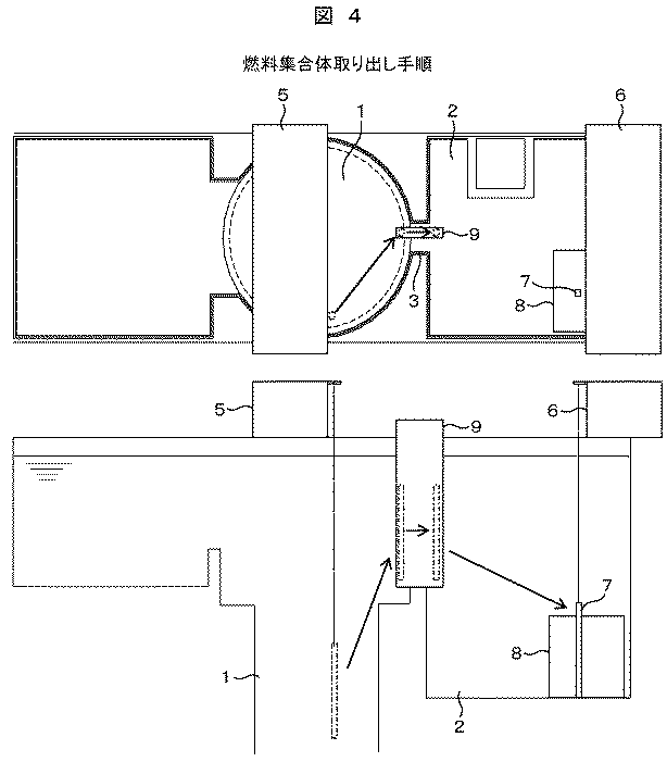
図4に、原子炉1と使用済み燃料プール2間のカナル部3の燃料集合体を移動する装置9,原子炉側の燃料集合体取扱い装置5と使用済み燃料プール側の燃料集合体取扱い装置6を用いて燃料集合体7を取り出す作業を示す。この図4に示すように、原子炉1側の燃料集合体取扱い装置5を用いて、原子炉1内から燃料集合体7を取り出し、カナル部の燃料集合体を移動する装置9まで移送し、当該燃料集合体7を移動する装置9に設置する。その後、燃料集合体7を移動する装置9は、燃料集合体7を原子炉1側から使用済み燃料プール2側に移動する。移動された燃料集合体7は、使用済み燃料プール側の燃料集合体取扱い装置5を用いて、使用済み燃料プール2の燃料保管ラック8に収納する。原子炉側の燃料集合体取扱い装置5は、カナル部の燃料集合体を移動する装置9に燃料集合体7を設置後、次に取り出す燃料集合体のエリアに移動し、次の燃料集合体7をハンドリングする。但し、複数の燃料を同時に取り扱うことができないため、燃料集合体を移動する装置9,原子炉側の燃料集合体取扱い装置5と使用済み燃料プール側の燃料集合体取扱い装置6には、それぞれ燃料集合体7の荷重を検出する機能を有し、燃料集合体を移動する装置9,原子炉側の燃料集合体取扱い装置5と使用済み燃料プール側の燃料集合体取扱い装置6のいずれかに燃料集合体の荷重が負荷されている場合、それ以外の装置には加重が付加できないインターロック機能を設ける。
FIG. 4 shows a device 9 for moving the fuel assembly in the
当該装置を用いて制御棒の取替え作業も短縮することができる。 The control rod replacement work can also be shortened using the apparatus.
1 原子炉
2 使用済み燃料プール
3 カナル部
4 燃料集合体仮置きラック
5 原子炉側の燃料集合体取扱い装置
6 使用済み燃料プール側の燃料集合体取扱い装置
7 燃料集合体
8 燃料保管ラック
9 燃料集合体を移動する装置
DESCRIPTION OF
Claims (2)
原子炉側と使用済み燃料プール側の2台の燃料取扱い機と前記原子炉と前記使用済み燃料プール間のカナル部に設置する燃料仮置きラックを用いて前記燃料集合体を取替えることを特徴とする原子力発電プラントの燃料集合体の取替え工法。 A fuel assembly replacement method for a nuclear power plant,
The fuel assembly is replaced by using two fuel handling machines on the reactor side and the spent fuel pool side, and a temporary fuel storage rack installed in a canal part between the reactor and the spent fuel pool, A replacement method for the fuel assembly of a nuclear power plant.
前記燃料仮置きラックに、原子炉側から使用済み燃料プール側に燃料を移動する機能を有した燃料移動装置を用いて制御棒を取替えることを特徴とする原子力プラントの燃料集合体の取替え工法。 In claim 1,
A method for replacing a fuel assembly in a nuclear power plant, wherein a control rod is replaced on the temporary fuel rack using a fuel transfer device having a function of moving fuel from a reactor side to a spent fuel pool side.
Priority Applications (1)
| Application Number | Priority Date | Filing Date | Title |
|---|---|---|---|
| JP2011041106A JP2012177630A (en) | 2011-02-28 | 2011-02-28 | Fuel replacement method of nuclear power plant |
Applications Claiming Priority (1)
| Application Number | Priority Date | Filing Date | Title |
|---|---|---|---|
| JP2011041106A JP2012177630A (en) | 2011-02-28 | 2011-02-28 | Fuel replacement method of nuclear power plant |
Publications (1)
| Publication Number | Publication Date |
|---|---|
| JP2012177630A true JP2012177630A (en) | 2012-09-13 |
Family
ID=46979553
Family Applications (1)
| Application Number | Title | Priority Date | Filing Date |
|---|---|---|---|
| JP2011041106A Withdrawn JP2012177630A (en) | 2011-02-28 | 2011-02-28 | Fuel replacement method of nuclear power plant |
Country Status (1)
| Country | Link |
|---|---|
| JP (1) | JP2012177630A (en) |
Cited By (1)
| Publication number | Priority date | Publication date | Assignee | Title |
|---|---|---|---|---|
| CN111584106A (en) * | 2020-04-17 | 2020-08-25 | 岭东核电有限公司 | Nuclear power station fuel unit substitution method, device, equipment and storage medium |
-
2011
- 2011-02-28 JP JP2011041106A patent/JP2012177630A/en not_active Withdrawn
Cited By (2)
| Publication number | Priority date | Publication date | Assignee | Title |
|---|---|---|---|---|
| CN111584106A (en) * | 2020-04-17 | 2020-08-25 | 岭东核电有限公司 | Nuclear power station fuel unit substitution method, device, equipment and storage medium |
| CN111584106B (en) * | 2020-04-17 | 2022-04-19 | 岭东核电有限公司 | Nuclear power station fuel unit substitution method, device, equipment and storage medium |
Similar Documents
| Publication | Publication Date | Title |
|---|---|---|
| Kim et al. | Reliability data update using condition monitoring and prognostics in probabilistic safety assessment | |
| SE532638C2 (en) | Method and apparatus for monitoring the operation of a nuclear reactor | |
| JP2012177630A (en) | Fuel replacement method of nuclear power plant | |
| Hyun et al. | Seamless remote dismantling system for heavy and highly radioactive components of Korean nuclear power plants | |
| JP2014063262A (en) | Stress distribution estimation method, and analysis method and analysis system using the same | |
| JP5640318B2 (en) | Nuclear power plant | |
| JP2014228483A (en) | Method and system for controlling refueling machine | |
| JP4981830B2 (en) | Axial output distribution prediction method and axial output distribution prediction apparatus | |
| JP2019105584A (en) | Reactor pressure vessel dismantling method | |
| Boucau et al. | Best practices for preparing vessel internals segmentation projects | |
| JP2016014958A (en) | Plant inspection plan creation method, plant inspection plan creation program, and plant inspection plan creation system | |
| JP6101660B2 (en) | Unused nuclear fuel processing system and unused nuclear fuel processing method | |
| JPWO2022118401A5 (en) | ||
| JP2011196903A (en) | Nuclear reactor platform and nuclear reactor inspection method | |
| CN105303315A (en) | Power equipment reliability evaluation method taking into consideration influence of maintenance randomness | |
| Mikuš | Power distribution gradients in WWER type cores and fuel failure root causes | |
| Varghese et al. | En-Masse Coolant Channel Replacement in Indian PHWR | |
| Kirby | Brookhaven Graphite Research Reactor (BGRR) D&D Project—11243 | |
| Boucau et al. | Importance of Upfront Preparatory Works for Vessel Internals Segmentation Projects-16096 | |
| Ferng | Predicting growth rate of wall thinning for severely degraded SG tubes using a statistical methodology | |
| JP2022108774A (en) | System for evaluating soundness of reactor structure and method for evaluating soundness of reactor structure | |
| JP5111587B2 (en) | How to store radioactive waste | |
| Sjoeblom et al. | Cost studies concerning decontamination and dismantling. The interim store for spent fuel at Studsvik | |
| Birks et al. | Accelerating the Decommissioning of the Sellafield Pile Fuel Storage Pond Using Innovative Remote Tooling Developed with the Supply Chain-16437 | |
| WO2014189597A3 (en) | In-containment spent fuel storage to limit spent fuel pool water makeup |
Legal Events
| Date | Code | Title | Description |
|---|---|---|---|
| A300 | Withdrawal of application because of no request for examination |
Free format text: JAPANESE INTERMEDIATE CODE: A300 Effective date: 20140513 |