JP2012177554A - Measurement display device - Google Patents
Measurement display device Download PDFInfo
- Publication number
- JP2012177554A JP2012177554A JP2011039139A JP2011039139A JP2012177554A JP 2012177554 A JP2012177554 A JP 2012177554A JP 2011039139 A JP2011039139 A JP 2011039139A JP 2011039139 A JP2011039139 A JP 2011039139A JP 2012177554 A JP2012177554 A JP 2012177554A
- Authority
- JP
- Japan
- Prior art keywords
- measurement
- display device
- screen
- message
- biosensor
- Prior art date
- Legal status (The legal status is an assumption and is not a legal conclusion. Google has not performed a legal analysis and makes no representation as to the accuracy of the status listed.)
- Pending
Links
Images


Abstract
Description
本発明は、着脱自在なバイオセンサを挿入して、バイオセンサに検体を点着し、検体中の基質の成分量を測定して表示する測定表示装置に関する。 The present invention relates to a measurement display device for inserting a detachable biosensor, spotting a sample on the biosensor, and measuring and displaying the amount of a substrate component in the sample.
従来から種々のバイオセンサ、および、バイオセンサを挿入して使用する測定表示装置が開示されている。例えば特許文献1には、図5に示すバイオセンサ100が記載されている。
Conventionally, various biosensors and measurement display devices using the biosensors are disclosed. For example, Patent Document 1 describes a
図5に示すバイオセンサ100の構造を図6に示す。図6(a)に示す、絶縁体からなる基板101が準備される。基板101は、例えば、ポリエチレンテレフタレートシート、ポリエチレンナフタレートシート、生分解性ポリエステル系樹脂シート、ポリアミドシート、ポリイミドシート、あるいは、セラミック基板からなる。
The structure of the
図6(b)に示すように、基板101上に、一対の測定電極102a、102b、一対の前方検知電極103a、103b、一対の後方検知電極104a、104bが形成される。測定電極102a、102b、前方検知電極103a、103b、後方検知電極104a、104bは、白金、金、パラジウム、インジウム−スズ酸化物などの導体薄膜により形成される。導体薄膜の形成方法としては、ホットスタンピング、真空蒸着、スパッタリングなどが用いられる。
As shown in FIG. 6B, a pair of
図6(c)に示すように、測定電極102a、102b、前方検知電極103a、103bの先端部、後方検知電極104a、104bの先端部の上に、反応部105が形成される。反応部105は、酸化還元酵素および電子受容体を含む膜である。反応部105は、液体状態の材料を所望の位置に滴下し、乾燥させて形成される。
As shown in FIG. 6C, the
図6(d)にスペーサー107を示す。図6(f)に示すように、基板101上にスペーサー107が載置される。スペーサー107は、測定電極102a、102b、前方検知電極103a、103bの先端、後方検知電極104a、104bの先端、および、反応部105を避けて載置される。
FIG. 6D shows the
図6(e)にカバー108を示す。図6(f)に示すように、スペーサー107の上にカバー108が載置される。カバー108により、測定電極102a、102b、前方検知電極103a、103b、後方検知電極104a、104b、および、反応部105が覆われる。スペーサー107により、カバー108と反応部105は一定間隔(概略スペーサー107の厚さ)で対向する。
FIG. 6E shows the
以上のようにして、図5に示すバイオセンサ100が作製される。
As described above, the
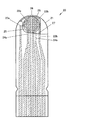
図5に示すように、検体(血液など)の供給口106は、バイオセンサ100の先端にある。供給口106に検体が点着されると、検体は反応部105とカバー108の隙間を毛細管現象により進行し、反応部105の表面上に広がる。
As shown in FIG. 5, a sample (blood or the like)
反応部105の表面上に広がった検体は、反応部105と反応する。このとき、測定電極102a、102b間に電位差が生じ、電子が授受される。反応部105の材料を適正に選択すると、検体の基質成分量(例えば血液中のグルコース量)に比例した電子の授受が生じる。一対の測定電極102a、102bは、基質成分量を測定することに用いられる。
The specimen spread on the surface of the
血液中のグルコース(血糖)を測定する場合、酸化還元酵素として、例えばグルコースオキシターゼ、電子受容体として、例えばフェリシアン化カリウムが用いられる。血液中のグルコース成分量が高いと、測定電極102a、102bの間で授受される電子の量が多くなる。
When measuring glucose (blood glucose) in blood, for example, glucose oxidase is used as an oxidoreductase, and potassium ferricyanide is used as an electron acceptor, for example. When the amount of glucose component in the blood is high, the amount of electrons transferred between the
前方検知電極103a、103bの先端は、供給口106近傍に位置する。前方検知電極103a、103b間に電流が流れることにより、検体が供給口106に点着したことが検知される。
The front ends of the
後方検知電極104a、104bの先端は、反応部105の後端に位置する。後方検知電極104a、104b間に電流が流れることにより、検体が後方検知電極104a、104bまで到達したことが検知される。これにより、反応部105の上に検体が十分に広がり、所望の反応が行なわれたことが推定される。
The front ends of the
図7に示すように、バイオセンサ100は測定表示装置200に挿入される。測定表示装置200は、筐体201と画面202を備える。
As shown in FIG. 7, the
図8に示すように、筐体201はその内部に、端子203、測定回路204、データ生成回路205、ドライバ回路206を備える。端子203には、バイオセンサ100の測定電極102a、102b、前方検知電極103a、103b、後方検知電極104a、104bが接続される。
As shown in FIG. 8, the
測定回路204は、端子203を通じて測定電極102a、102b、前方検知電極103a、103b、後方検知電極104a、104bに所定の電圧を印加する。
The
前方検知電極103a、103b間に流れた電流から検体が供給口106に点着したことが検知される。後方検知電極104a、104b間に流れた電流から、検体が後方検知電極104a、104bまで到達したことが検知される。そして、測定電極102a、102b間に流れた電流から検体の基質成分量が測定される。
From the current flowing between the
データ生成回路205は、基質成分量の表示データを生成する。ドライバ回路206は、画面202に基質成分量を表示させる。
The
バイオセンサ100が測定表示装置200に挿入された後、測定回路204により基質成分量が測定され、画面202に表示される。バイオセンサ100の反応部105は不可逆反応をするため、バイオセンサ100は1回使用すると再度の使用はできない。そのため、バイオセンサ100は測定の度に交換される。
After the
測定表示装置200は携帯に便利なように、小型に作られている。画面202も小型であり、僅かの内容しか表示できない。そのため、表示内容は画面を順次切り替えて表示される。画面を順次切り替えて表示することを、本明細書では画面表示の展開という。
The
図9に、測定開始から測定完了までの、従来の画面202表示の展開を示す。
FIG. 9 shows the development of the
「OFF状態」では画面202に何も表示されていない。スイッチ207を入れると、画面202は「全画面表示」となる。これは、表示に欠落がないか確認するために用いられる。所定の時間経過後、「全画面表示」から「現在の日付と時間の表示」に変更される。これは、日付と時間に誤りがないか確認するために用いられる。
In the “OFF state”, nothing is displayed on the
バイオセンサ100には、正常な測定のできる適正温度範囲がある。そのため測定表示装置200の温度が適正温度範囲外であるとき、「温度警告」が表示される。しかし測定表示装置200の温度が適正温度範囲内であるときは、「温度警告」は表示されない。
The
次に、バイオセンサ100を測定表示装置200に挿入する旨の指示が表示される。
Next, an instruction to insert the
バイオセンサ100を測定表示装置200に挿入すると、「前回の測定値」が表示される。
When the
所定時間経過後、検体をバイオセンサ100に点着する旨の指示が表示される。
After a predetermined time has elapsed, an instruction to spot the sample on the
検体をバイオセンサ100に点着すると、検体は反応部105の上に広がり、反応部105との反応が進行する。反応には所定の時間(5秒〜10秒程度)が必要である。このとき反応中であることを示すため、反応完了までの待時間(例えば、「5、4、3、2、1、0」)が表示される。
When the sample is spotted on the
反応が完了して検体の基質成分量の計算が終わると、「測定値」が表示される。これにより、一連の測定が終了する。 When the reaction is completed and the calculation of the amount of the substrate component of the sample is completed, the “measured value” is displayed. Thereby, a series of measurements is completed.
バイオセンサ100と測定表示装置200の最も一般的な使用者は、血糖値を自分で測定して、自己管理を行なっている糖尿病患者である。血糖値測定の頻度は患者によって異なるが、少ない人で、2回/日×1日/週=2回/週程度、多い人では、6回/日×7日/週=42回/週もの測定が必要である。
The most common users of the
血糖値の自己測定は、時間と手間と費用がかかるため、医師の指示通りに定期的に測定を行なう意欲を保つのが難しい。また、特に測定回数が多い場合(例えば、6回/日)、スケジュール通りの測定をしたか否か分からなくなる可能性がある。 Since self-measurement of blood glucose level takes time, labor, and expense, it is difficult to keep the willingness to perform regular measurement as instructed by a doctor. In addition, particularly when the number of times of measurement is large (for example, 6 times / day), there is a possibility that it is not known whether or not the measurement was performed according to the schedule.
しかし、従来の測定表示装置200の画面202表示の展開は、上記の問題を考慮した展開になっていなかった。
However, the
従来の測定表示装置の画面表示の展開は、自己測定者(患者)の測定意欲を保つことを考慮した展開ではなかった。また、従来の測定表示装置の画面表示の展開は、スケジュール通りの測定をしたか否か明確に分かるような展開ではなかった。 The development of the screen display of the conventional measurement display device has not been a development considering keeping the measurement desire of the self-measuring person (patient). Further, the development of the screen display of the conventional measurement display device is not such a development that clearly shows whether or not the measurement was performed as scheduled.
本発明の目的は、自己測定者の測定意欲を保つような画面展開を備えた測定表示装置を実現することである。また、本発明の目的は、スケジュール通りの測定をしたか否かが明確に分かるような画面展開を備えた測定表示装置を実現することである。 An object of the present invention is to realize a measurement display device having a screen development that keeps the self-measuring person's desire to measure. Another object of the present invention is to realize a measurement display device having a screen development that clearly shows whether or not the measurement has been performed as scheduled.
(1)本発明の測定表示装置においては、反応部を備えたバイオセンサを筺体に挿入する。本発明の測定表示装置の備える画面は、反応部に導入した検体の基質の成分量を表示する。本発明の測定表示装置では、画面の表示の展開の初期画面として、文字、イラスト、写真のいずれか、あるいはそれらの組合せからなるメッセージが事前設定できる。
(2)本発明の測定表示装置の備えるメッセージは測定の日毎に入れ替わる。
(3)本発明の測定表示装置の備えるメッセージは、総数が、所定の期間内の測定日数と同数であり、設定した順序で測定日毎に入れ替わり、期間の完了により最初のメッセージに戻る。
(4)本発明の測定表示装置の備えるメッセージは測定毎に入れ替わる。
(5)本発明の測定表示装置の備えるメッセージは、総数が、所定の期間内の測定回数と同数であり、設定した順序で測定毎に入れ替わり、期間の完了により最初のメッセージに戻る。
(6)本発明の測定表示装置は血糖値測定表示装置である。
(1) In the measurement display device of the present invention, a biosensor provided with a reaction part is inserted into a housing. The screen provided in the measurement display device of the present invention displays the amount of the substrate component of the sample introduced into the reaction part. In the measurement display device of the present invention, a message composed of any one of characters, illustrations, and photographs, or a combination thereof can be preset as an initial screen for developing the display on the screen.
(2) The message provided in the measurement display device of the present invention is changed every measurement day.
(3) The total number of messages included in the measurement display device of the present invention is the same as the number of measurement days within a predetermined period, and the messages are switched for each measurement day in the set order, and return to the first message upon completion of the period.
(4) The message provided in the measurement display device of the present invention is changed every measurement.
(5) The total number of messages included in the measurement display device of the present invention is the same as the number of measurements within a predetermined period, and is switched for each measurement in the set order, and returns to the first message upon completion of the period.
(6) The measurement display device of the present invention is a blood glucose level measurement display device.
本発明の測定表示装置は、自己測定者の測定意欲を保つような画面展開を備える。また、本発明の測定表示装置は、スケジュール通りの測定をしたか否か明確に分かる画面展開を備える。 The measurement display device of the present invention has a screen development that keeps the self-measuring person's desire to measure. Further, the measurement display device of the present invention has a screen development that clearly shows whether or not the measurement has been performed as scheduled.
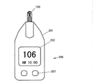
図1に本発明の測定表示装置10の一例を示す。測定表示装置10は、筐体11と画面12を備える。筐体11はスイッチ17と、PC(パーソナルコンピューター)、携帯電話等の情報通信機器との外部機器接続端子18を備える。測定表示装置10の先端に、バイオセンサ20が挿入される。
FIG. 1 shows an example of the
図2に本発明の測定表示装置10に挿入されるバイオセンサ20の一例を示す。図2に示すバイオセンサ20においては、基板21上に、一対の測定電極22a、22b、一対の前方検知電極23a、23b、一対の後方検知電極24a、24bが形成される。
FIG. 2 shows an example of the
基板21は、例えば、ポリエチレンテレフタレートシート、ポリエチレンナフタレートシート、生分解性ポリエステル系樹脂シート、ポリアミドシート、ポリイミドシート、あるいは、セラミック基板からなる。
The
測定電極22a、22b、前方検知電極23a、23b、後方検知電極24a、24bは、白金、金、パラジウム、インジウム−スズ酸化物などの導体薄膜から形成される。導体薄膜は、ホットスタンピング、真空蒸着、スパッタリングなどの手法により形成される。
The
測定電極22a、22b、前方検知電極23a、23bの先端部、後方検知電極24a、24bの先端部の上に、反応部25が形成される。
A
反応部25は、酸化還元酵素および電子受容体を含む膜である。反応部25は、液体状態の材料を所望の位置に滴下し、乾燥させて形成される。
The
基板21上にスペーサー27が載置される。スペーサー27は、測定電極22a、22b、前方検知電極23a、23bの先端、後方検知電極24a、24bの先端、および、反応部25を避けて載置される。
A
スペーサー27の上にカバー28が載置される。カバー28により、測定電極22a、22b、前方検知電極23a、23b、後方検知電極24a、24b、および反応部25が覆われる。スペーサー27により、カバー28と反応部25は一定間隔(概略スペーサー27の厚さ)で対向する。
A
検体(血液など)の供給口26は、バイオセンサ20の先端にある。供給口26に検体が点着されると、検体は反応部25とカバー28の隙間を毛細管現象により進行し、反応部25の表面上に広がる。
A specimen (blood or the like)
反応部25の表面上に広がった検体は、反応部25と反応する。このとき、測定電極22a、22b間に電位差が生じ、電子が授受される。反応部25の材料を適正に選択すると、検体の基質成分量(例えば血液中のグルコース量)に比例した電子の授受が生じる。一対の測定電極22a、22bは、基質成分量を測定することに用いられる。
The specimen spread on the surface of the
血液中のグルコース(血糖)を測定する場合、酸化還元酵素として、例えばグルコースオキシターゼ、電子受容体として、例えばフェリシアン化カリウムが用いられる。血液中のグルコース成分量が高いと、測定電極22a、22bの間で授受される電子の量が多くなる。
When measuring glucose (blood glucose) in blood, for example, glucose oxidase is used as an oxidoreductase, and potassium ferricyanide is used as an electron acceptor, for example. When the amount of glucose component in the blood is high, the amount of electrons transferred between the
前方検知電極23a、23bの先端は、供給口26近傍に位置する。前方検知電極23a、23b間に電流が流れることにより、検体が供給口26に点着したことが検知される。
The front ends of the
後方検知電極24a、24bの先端は、反応部25の後端に位置する。後方検知電極24a、24b間に電流が流れることにより、検体が後方検知電極24a、24bまで到達したことが検知される。これにより、反応部25の上に検体が十分広がり、所望の反応が行なわれたことが推定される。
The front ends of the
図3に示すように、筐体11はその内部に、端子13、測定回路14、データ生成回路15、ドライバ回路16、外部機器接続端子18を備える。端子13には、バイオセンサ20の測定電極22a、22b、前方検知電極23a、23b、後方検知電極24a、24bが接続される。外部機器接続端子18には、PC、携帯電話等の事前設定用情報通信機器19が接続される。
As shown in FIG. 3, the
測定回路14は、端子13を通じて測定電極22a、22b、前方検知電極23a、23b、後方検知電極24a、24bに所定の電圧を印加する。前方検知電極23a、23b間に流れた電流から検体が供給口26に点着したことが検知される。後方検知電極24a、24b間に流れた電流から、検体が後方検知電極24a、24bまで到達したことが検知される。そして、測定電極22a、22b間に流れた電流から検体の基質成分量(例えば血糖値)が測定される。
The
データ生成回路15は、基質成分量の表示データを生成する。ドライバ回路16は、画面12に基質成分量を表示させる。バイオセンサ20が測定表示装置10に挿入された後、測定回路14により基質成分量が測定され、画面12に基質成分量が表示される。バイオセンサ20の反応部25は不可逆反応を行なうため、バイオセンサ20は1回の使用で使えなくなる。そのため、測定毎にバイオセンサ20は交換される。
The
測定表示装置10は携帯に容易なように、小型に作られている。画面12も小型であり、僅かの内容しか表示できない。そのため、表示内容は画面を順次切り替えて表示される。
The
本発明の測定表示装置10においては、PC、携帯電話等の事前設定用情報通信機器19を用いて、測定表示装置10の画面12表示の展開を、事前に設定することができる。(本発明の測定表示装置10は、画面12表示の展開を事前に設定しないときは、従来の測定表示装置200と同じように使用できる。)事前設定項目として、測定回数(回/日、日/週)、食事の前後の測定の有無、測定時刻等がある。これらは通常、医師の指示による。
In the
さらに事前設定項目として、各測定時の初期画面(OFF状態からスイッチ17を入れた時に表示される最初の画面表示)が設定できる。初期画面に設定されるメッセージとして、文字、イラストあるいは写真からなるメッセージが利用できる。これらのメッセージは使用者が好みに応じて自由に設定できる。メッセージは測定の励みになるものが望ましい。文字の例として、自分自身の決意の言葉、あるいは医師や家族の激励の言葉がある。イラストの例として、アニメのヒーローやヒロインがある。写真の例として、子や孫やペット、風景、花の写真がある。このようなメッセージを見ることにより、使用者は測定に意欲が沸き、測定の億劫さを避けることが出来る。
Furthermore, an initial screen for each measurement (the first screen displayed when the
メッセージは固定でも良いが、測定の日毎に入れ替わり、所定期間(例えば一週間)で一巡することが望ましい。例えば、月曜、水曜、金曜に1回ずつ測定しなければならないときは、3種類のメッセージA、B、Cを事前設定しておく。この場合、初期画面は、月曜の未明にメッセージAに入れ替わり、水曜の未明にメッセージBに入れ替わり、金曜の未明にメッセージCに入れ替わり、次の月曜の未明に再びメッセージAに入れ替わる。但し、スケジュール通りに測定をしないと、メッセージは入れ替わらない。 Although the message may be fixed, it is preferable that the message is changed every measurement day and makes a round in a predetermined period (for example, one week). For example, when it is necessary to measure once every Monday, Wednesday, and Friday, three types of messages A, B, and C are preset. In this case, the initial screen is changed to message A at dawn on Monday, changed to message B at dawn on Wednesday, changed to message C at dawn on Friday, and changed to message A again at dawn on the next Monday. However, if the measurement is not performed according to the schedule, the message will not be replaced.
このように事前設定すると、初期画面を見るだけで、スケジュールに従った測定をしているかどうか確認できる。メッセージAが月曜の測定に設定されており、メッセージBが水曜の測定に設定されているから、水曜の測定をしようとしたとき、初期画面がメッセージBであれば、測定はスケジュール通り行なわれていたことが分かる。しかし初期画面がメッセージAであれば、月曜の測定は行なわれていなかったことになる。つまり初期画面がメッセージAであることから、月曜の測定を忘れていたことに容易に気づく。 If pre-set in this way, you can check whether you are measuring according to the schedule just by looking at the initial screen. Since message A is set for measurement on Monday and message B is set for measurement on Wednesday, if the initial screen is message B when trying to measure on Wednesday, the measurement is being performed as scheduled. I understand that. However, if the initial screen is message A, Monday measurement has not been performed. That is, since the initial screen is message A, it is easy to notice that the measurement on Monday has been forgotten.
もっと測定回数が多いときは、メッセージは各測定毎に入れ替わり、所定期間(例えば一週間)で一巡することが望ましい。例えば、毎日、昼食の前後に測定しなければならないときは、14種類のメッセージA、B、C、D、E、F、G、H、I、J、K、L、M、Nを事前設定しておく。日曜の昼食前のメッセージがA、昼食後のメッセージがB、月曜の昼食前のメッセージがC、昼食後のメッセージがD、...、土曜の昼食前のメッセージがM、昼食後のメッセージがNである。これらのメッセージは、スケジュール通りの測定をすることにより、設定通りに入れ替わる。 When the number of times of measurement is larger, the message is preferably changed for each measurement, and it is desirable to make a round in a predetermined period (for example, one week). For example, if you need to measure every day before and after lunch, preset 14 messages A, B, C, D, E, F, G, H, I, J, K, L, M, N Keep it. The message before lunch on Sunday is A, the message after lunch is B, the message before lunch on Monday is C, the message after lunch is D, ..., the message before lunch on Saturday is M, the message after lunch N. These messages are replaced as set by measuring according to the schedule.
このように事前設定すると、初期画面を見るだけで、スケジュールに従った測定をしているかどうか確認できる。メッセージAが日曜の昼食前の測定について設定されており、メッセージBが日曜の昼食後の測定について設定されているから、日曜の昼食後の測定をしようとしたとき、初期画面がメッセージBであれば、その日の測定はスケジュール通り行なわれていたことが分かる。しかし初期画面がメッセージAであれば、昼食前の測定は行なわれていなかったことになる。つまり初期画面がメッセージAであることから、昼食前の測定を忘れていたことに容易に気づく。 If pre-set in this way, you can check whether you are measuring according to the schedule just by looking at the initial screen. Since message A is set for measurement before lunch on Sunday and message B is set for measurement after lunch on Sunday, the initial screen should be message B when trying to measure after lunch on Sunday. In other words, it can be seen that the measurement of the day was performed according to the schedule. However, if the initial screen is message A, the measurement before lunch was not performed. That is, since the initial screen is the message A, it is easy to notice that the measurement before lunch was forgotten.
従来の測定表示装置200でも、前回の測定時刻を表示することは可能であったが、前回の測定時刻はスケジュール通りでなくても見逃がす可能性がある。本発明の測定表示装置10のように、初期画面が毎回変わる方が誤りを見逃がす可能性が低い。
Even with the conventional
図4に測定開始から測定完了までの、本発明の測定表示装置10の画面12表示の展開を示す。本発明の測定表示装置10の画面12表示の展開は、事前設定をしない場合と、事前設定をした場合で異なる。
FIG. 4 shows the development of the
(事前設定をしない場合)
事前設定をしない場合、従来の測定表示装置200と同じ画面表示の展開となる。
(If not set in advance)
When the presetting is not performed, the same screen display as the conventional
「OFF状態」では画面12に何も表示されていない。OFF状態でスイッチ17を入れると、画面12は「全画面表示」となる。これは、表示ドットに欠落がないか確認するために用いられる。所定の時間経過後、「全画面表示」から「現在の日付と時間の表示」に変更される。これは、日付と時間に誤りがないか確認するために用いられる。
In the “OFF state”, nothing is displayed on the
バイオセンサ20には、正常な測定のできる適正温度範囲(例えば、10℃〜35℃)がある。そのため測定表示装置10の温度が適正温度範囲外であるときは、「温度警告」が表示される。しかし測定表示装置10の温度が適正温度範囲内であるときは、「温度警告」は表示されない。
The
次に、バイオセンサ20を測定表示装置10に挿入する指示が表示される。
Next, an instruction to insert the
バイオセンサ20を測定表示装置10に挿入すると、「前回の測定値」が表示される。
When the
所定時間経過後、検体をバイオセンサ20に点着する指示が表示される。
After a predetermined time has elapsed, an instruction to spot the sample on the
検体をバイオセンサ20に点着すると、検体は反応部25の上に広がり、反応部25との反応が進行する。反応には所定の時間(5秒〜10秒程度)が必要である。このとき反応中であることを示すため、反応完了までの待時間(例えば、「5、4、3、2、1、0」)が表示される。
When the sample is spotted on the
反応が完了して、検体の基質成分量の計算が終わると、今回の「測定値」が表示される。これにより、一連の測定が終了する。 When the reaction is completed and the calculation of the amount of the substrate component of the sample is completed, the current “measured value” is displayed. Thereby, a series of measurements is completed.
事前設定をしない場合、画面12表示の展開は、従来の画面202表示の展開と同じである。そのため本発明の測定表示装置10は、PC、携帯電話等の情報通信機器が無い、時間が無い、メッセージは不要などにより事前設定をしない場合、従来の測定表示装置200と同様に使用できる。従って、事前設定をしなくても問題はない。
When the presetting is not performed, the development of the
(事前設定をした場合)
「OFF状態」では画面12に何も表示されていない。OFF状態でスイッチ17を入れると、画面12は事前設定した文字、イラスト、写真、あるいはそれらを組み合わせたメッセージになる。メッセージにより得られる効果は、測定に対して意欲を持てる(飽きがこない)ことと、スケジュール通りの測定になっているかどうかを容易に確認できることである。
(When pre-configured)
In the “OFF state”, nothing is displayed on the
所定の時間経過後、画面12は「全画面表示」となる。これは、表示ドットに欠落がないか確認するために用いられる。更に所定の時間経過後、画面12は「全画面表示」から「現在の日付と時間の表示」に変更される。これは、日付と時間に誤りがないか確認するために用いられる。
After a predetermined time has elapsed, the
測定表示装置10の温度が適正温度範囲外であるとき、「温度警告」が表示される。しかし測定表示装置10の温度が適正温度範囲内であるときは、「温度警告」は表示されない。
When the temperature of the
次に、バイオセンサ20を測定表示装置10に挿入する指示が表示される。
Next, an instruction to insert the
バイオセンサ20を測定表示装置10に挿入すると、「前回の測定値」が表示される。
When the
所定時間経過後、検体をバイオセンサ20に点着する指示が表示される。
After a predetermined time has elapsed, an instruction to spot the sample on the
検体をバイオセンサ20に点着すると、検体は反応部25の上に広がり、反応部25との反応が進行する。反応には所定の時間(5秒〜10秒程度)が必要である。このとき反応中であることを示すため、反応完了までの待時間(例えば、「5、4、3、2、1、0」)が表示される。
When the sample is spotted on the
反応が完了して、検体の基質成分量の計算が終わると、今回の「測定値」が表示される。これにより、一連の測定が終了する。 When the reaction is completed and the calculation of the amount of the substrate component of the sample is completed, the current “measured value” is displayed. Thereby, a series of measurements is completed.
本発明により、自己測定者の測定意欲を保つような画面展開を備えた測定表示装置が実現される。また、本発明により、スケジュール通りの測定をしたか否かが明確に分かるような画面展開を備えた測定表示装置が実現される。 According to the present invention, a measurement display device having a screen development that keeps the self-measuring person's desire to measure is realized. In addition, according to the present invention, a measurement display device having a screen development that clearly shows whether or not the measurement has been performed according to the schedule is realized.
10 測定表示装置
11 筐体
12 画面
13 端子
14 測定回路
15 データ生成回路
16 ドライバ回路
17 スイッチ
18 外部機器接続端子
19 事前設定用情報通信機器
20 バイオセンサ
21 基板
22a、22b 測定電極
23a、23b 前方検知電極
24a、24b 後方検知電極
25 反応部
26 供給口
27 スペーサー
28 カバー
100 バイオセンサ
101 基板
102a、102b 測定電極
103a、103b 前方検知電極
104a、104b 後方検知電極
105 反応部
106 供給口
107 スペーサー
108 カバー
200 測定表示装置
201 筐体
202 画面
203 端子
204 測定回路
205 データ生成回路
206 ドライバ回路
207 スイッチ
DESCRIPTION OF
Claims (6)
前記反応部に導入した検体の基質の成分量を表示する画面を備え、
前記画面の表示の展開の初期画面として、文字、イラスト、写真のいずれか、あるいはそれらの組合せからなるメッセージが事前設定可能である測定表示装置。 A housing for inserting a biosensor equipped with a reaction part;
Provided with a screen that displays the amount of the substrate component of the sample introduced into the reaction section,
A measurement display device capable of presetting a message composed of any one of a character, an illustration, and a photo, or a combination thereof as an initial screen for developing the display on the screen.
Priority Applications (2)
| Application Number | Priority Date | Filing Date | Title |
|---|---|---|---|
| JP2011039139A JP2012177554A (en) | 2011-02-25 | 2011-02-25 | Measurement display device |
| CN2012100482096A CN102650613A (en) | 2011-02-25 | 2012-02-24 | Measurement display device |
Applications Claiming Priority (1)
| Application Number | Priority Date | Filing Date | Title |
|---|---|---|---|
| JP2011039139A JP2012177554A (en) | 2011-02-25 | 2011-02-25 | Measurement display device |
Publications (1)
| Publication Number | Publication Date |
|---|---|
| JP2012177554A true JP2012177554A (en) | 2012-09-13 |
Family
ID=46692661
Family Applications (1)
| Application Number | Title | Priority Date | Filing Date |
|---|---|---|---|
| JP2011039139A Pending JP2012177554A (en) | 2011-02-25 | 2011-02-25 | Measurement display device |
Country Status (2)
| Country | Link |
|---|---|
| JP (1) | JP2012177554A (en) |
| CN (1) | CN102650613A (en) |
Cited By (1)
| Publication number | Priority date | Publication date | Assignee | Title |
|---|---|---|---|---|
| JP2020516993A (en) * | 2017-03-28 | 2020-06-11 | アセンシア・ディアベティス・ケア・ホールディングス・アーゲー | Diabetes management system, method and apparatus for user reminders, pattern recognition and interfaces |
Citations (4)
| Publication number | Priority date | Publication date | Assignee | Title |
|---|---|---|---|---|
| JP2005070953A (en) * | 2003-08-21 | 2005-03-17 | Riso Kagaku Corp | Non-smoking support device |
| JP2008304197A (en) * | 2007-06-05 | 2008-12-18 | Gunze Ltd | Biosensor |
| JP2009523469A (en) * | 2005-12-29 | 2009-06-25 | ガイダンス インタラクティブ ヘルスケア インコーポレイテッド | Programmable device, system, and method for encouraging monitoring of medical parameters |
| WO2010143115A1 (en) * | 2009-06-12 | 2010-12-16 | Koninklijke Philips Electronics N.V. | A medical device having a reminder function |
Family Cites Families (6)
| Publication number | Priority date | Publication date | Assignee | Title |
|---|---|---|---|---|
| US6968375B1 (en) * | 1997-03-28 | 2005-11-22 | Health Hero Network, Inc. | Networked system for interactive communication and remote monitoring of individuals |
| US6699188B2 (en) * | 2000-06-22 | 2004-03-02 | Guidance Interactive Technologies | Interactive reward devices and methods |
| US20030211617A1 (en) * | 2002-05-07 | 2003-11-13 | International Business Machines Corporation | Blood glucose meter that reminds the user to test after a hypoglycemic event |
| US8071028B2 (en) * | 2003-06-12 | 2011-12-06 | Abbott Diabetes Care Inc. | Method and apparatus for providing power management in data communication systems |
| US20080015422A1 (en) * | 2005-12-29 | 2008-01-17 | Guidance Interactive Healthcare, Inc. | Combined peripheral and health monitoring devices |
| EP2529784B1 (en) * | 2006-03-23 | 2019-05-01 | Becton, Dickinson and Company | Method for improved diabetes data management and use employing wireless connectivity between patients and healthcare providers and repository of diabetes management information |
-
2011
- 2011-02-25 JP JP2011039139A patent/JP2012177554A/en active Pending
-
2012
- 2012-02-24 CN CN2012100482096A patent/CN102650613A/en active Pending
Patent Citations (4)
| Publication number | Priority date | Publication date | Assignee | Title |
|---|---|---|---|---|
| JP2005070953A (en) * | 2003-08-21 | 2005-03-17 | Riso Kagaku Corp | Non-smoking support device |
| JP2009523469A (en) * | 2005-12-29 | 2009-06-25 | ガイダンス インタラクティブ ヘルスケア インコーポレイテッド | Programmable device, system, and method for encouraging monitoring of medical parameters |
| JP2008304197A (en) * | 2007-06-05 | 2008-12-18 | Gunze Ltd | Biosensor |
| WO2010143115A1 (en) * | 2009-06-12 | 2010-12-16 | Koninklijke Philips Electronics N.V. | A medical device having a reminder function |
Cited By (2)
| Publication number | Priority date | Publication date | Assignee | Title |
|---|---|---|---|---|
| JP2020516993A (en) * | 2017-03-28 | 2020-06-11 | アセンシア・ディアベティス・ケア・ホールディングス・アーゲー | Diabetes management system, method and apparatus for user reminders, pattern recognition and interfaces |
| JP7191037B2 (en) | 2017-03-28 | 2022-12-16 | アセンシア・ディアベティス・ケア・ホールディングス・アーゲー | Diabetes Management Systems, Methods, and Apparatus for User Reminders, Pattern Recognition, and Interfaces |
Also Published As
| Publication number | Publication date |
|---|---|
| CN102650613A (en) | 2012-08-29 |
Similar Documents
| Publication | Publication Date | Title |
|---|---|---|
| CN102770868B (en) | Analyte testing method and system with high and low blood glucose trends notification | |
| US9291591B2 (en) | Universal test strip port | |
| KR102035990B1 (en) | Accurate analyte measurements for electrochemical test strip based on sensed physical characteristic(s) of the sample containing the analyte | |
| US20130318439A1 (en) | Analyte testing method and system with high and low analyte trends notification | |
| US20100198142A1 (en) | Multi-Function Analyte Test Device and Methods Therefor | |
| JP6764784B2 (en) | Data management unit that supports health management | |
| BR112013012462A2 (en) | analyte test method and system with notification of high and low analyte trends | |
| US20150144507A1 (en) | Folded biosensor | |
| JP2011252851A (en) | Measurement display device attached with biosensor | |
| US20160210430A1 (en) | Data management unit for supporting health control | |
| ES2747074T3 (en) | Analyte measurement system that records user menu options | |
| JP2012177554A (en) | Measurement display device | |
| TW201415404A (en) | Method and system to manage diabetes using multiple risk indicators for a person with diabetes | |
| JP2015026233A (en) | Server device helping user adhere to dosing | |
| JP5452436B2 (en) | Measurement display device | |
| JP5722667B2 (en) | Measurement display device | |
| CN103364459B (en) | Measurement display device | |
| KR20130116290A (en) | Analyte testing method and system with high and low analyte trends notification | |
| Kulkarni | Helping Patients With Diabetes Select a Blood Glucose Monitor |
Legal Events
| Date | Code | Title | Description |
|---|---|---|---|
| A621 | Written request for application examination |
Free format text: JAPANESE INTERMEDIATE CODE: A621 Effective date: 20131225 |
|
| A977 | Report on retrieval |
Free format text: JAPANESE INTERMEDIATE CODE: A971007 Effective date: 20140514 |
|
| A131 | Notification of reasons for refusal |
Free format text: JAPANESE INTERMEDIATE CODE: A131 Effective date: 20140520 |
|
| A02 | Decision of refusal |
Free format text: JAPANESE INTERMEDIATE CODE: A02 Effective date: 20140924 |