JP2012177308A - Cooling system of internal combustion engine - Google Patents
Cooling system of internal combustion engine Download PDFInfo
- Publication number
- JP2012177308A JP2012177308A JP2011039262A JP2011039262A JP2012177308A JP 2012177308 A JP2012177308 A JP 2012177308A JP 2011039262 A JP2011039262 A JP 2011039262A JP 2011039262 A JP2011039262 A JP 2011039262A JP 2012177308 A JP2012177308 A JP 2012177308A
- Authority
- JP
- Japan
- Prior art keywords
- cooling
- temperature
- cooling water
- abnormality
- value
- Prior art date
- Legal status (The legal status is an assumption and is not a legal conclusion. Google has not performed a legal analysis and makes no representation as to the accuracy of the status listed.)
- Granted
Links
Images


Landscapes
- Combined Controls Of Internal Combustion Engines (AREA)
Abstract
Description
本発明は、冷却液を循環させて内燃機関を冷却する冷却装置に関する。 The present invention relates to a cooling device that cools an internal combustion engine by circulating a coolant.
従来、ラジエータを介して冷却液を循環させる状態と、前記ラジエータを迂回して冷却液を循環させる状態とに切り替える電制サーモスタットバルブを備えた内燃機関の冷却装置が知られている(例えば、特許文献1参照)。 2. Description of the Related Art Conventionally, a cooling device for an internal combustion engine having an electric thermostat valve that switches between a state in which a coolant is circulated through a radiator and a state in which the coolant is circulated around the radiator is known (for example, a patent Reference 1).
上記のように、電制サーモスタットバルブを備えた冷却装置では、サーモスタットの開弁温度(ラジエータを介した循環を開始させる冷却液温度)を高くすることで、冷却液の温度を上げ、内燃機関のフリクションを低下させることが可能である。
しかし、冷却液の温度を高くすると、循環系内の冷却液に空気が混入する異常が発生し、冷却液の循環系内における圧力を高圧側に保てなくなった場合に、冷却液が沸騰し易く、オーバーヒートが発生する可能性があった。
As described above, in a cooling device equipped with an electronically controlled thermostat valve, the temperature of the coolant is increased by increasing the valve opening temperature of the thermostat (the coolant temperature at which circulation through the radiator is started). It is possible to reduce the friction.
However, when the temperature of the coolant is raised, an abnormality occurs in which air enters the coolant in the circulation system, and the coolant boils when the pressure of the coolant in the circulation system cannot be maintained on the high pressure side. It was easy to cause overheating.
そこで、本願発明は、循環系における冷却液の異常の有無を判定できる冷却装置を提供することを目的とする。 Then, this invention aims at providing the cooling device which can determine the presence or absence of abnormality of the cooling fluid in a circulation system.
そのため、本願発明では、冷却液の温度を検出し、検出した冷却液の温度の変化に基づき、冷却液の異常の有無を判定する。 Therefore, in the present invention, the temperature of the coolant is detected, and the presence or absence of abnormality of the coolant is determined based on the detected change in the temperature of the coolant.
上記発明によると、冷却液の温度変化に基づき、例えば空気混入などの冷却液の異常の有無を判定できるので、冷却液の異常に対して対策を施してオーバーヒートの発生を未然に抑制することが可能となる。 According to the above invention, based on the temperature change of the coolant, it can be determined whether there is an abnormality in the coolant such as air mixing, for example, so that countermeasures against the coolant abnormality can be taken to prevent the occurrence of overheating in advance. It becomes possible.
以下に本発明に係る内燃機関の冷却装置の実施形態を説明する。
図1は、実施形態における内燃機関の冷却装置のシステム図である。
エンジン(内燃機関)1のジリンダブロックやシリンダヘッドには、冷却水(冷却液)通路2が形成されており、この冷却水通路(ウォータジャケット)2の出口とラジエータ3の入口3aとが、冷却水配管4で接続されている。
そして、冷却水通路2を通過することでエンジン1の熱を奪い温度上昇した冷却水は、冷却水配管4を介してラジエータ(空冷式放熱器)3に送られる。
Embodiments of a cooling apparatus for an internal combustion engine according to the present invention will be described below.
FIG. 1 is a system diagram of a cooling device for an internal combustion engine according to an embodiment.
A cooling water (cooling liquid)
And the cooling water which took the heat of the
ラジエータ3は、ラジエータ3に風を当てて放熱させる電動式の冷却ファン(ラジエータファン)5を備えている。
ラジエータ3の出口3bとエンジン1の冷却水通路2の入口とは、冷却水配管6で接続される。
The
The
冷却水通路2の入口と冷却水配管6の端部との間には、ラジエータ3で放熱して温度低下した冷却水を再びエンジン1の冷却水通路2に送り込むために、エンジン1で駆動される機械式ウォータポンプ7を設けてある。
また、エンジン1の停止中に冷却水を循環させるために、冷却水配管6の途中には、電動式ウォータポンプ8を設けてある。
Between the inlet of the
An
尚、機械式ウォータポンプ7と電動式ウォータポンプ8との一方を備える冷却装置であってもよく、図2には、機械式ウォータポンプ7を備えずに電動式ウォータポンプ8を備えた冷却装置を示してある。
図2のシステム図は、図1のシステム図に対して、機械式ウォータポンプ7を省略している点のみが異なる。
In addition, the cooling apparatus provided with one of the mechanical water pump 7 and the
The system diagram of FIG. 2 differs from the system diagram of FIG. 1 only in that the mechanical water pump 7 is omitted.
また、冷却水配管4の途中と、ラジエータ3の出口3bと電動式ウォータポンプ8との間の冷却水配管6とを接続するバイパス配管9を設けてある。
バイパス配管9は、ラジエータ3を迂回して冷却水を循環させる循環系を構成し、ラジエータ3を迂回して循環させる冷却水の流量(ラジエータ3を迂回させるか否か)は、電制サーモスタットバルブ10によって制御される。
Further, a bypass pipe 9 is provided for connecting the
The bypass pipe 9 constitutes a circulation system that bypasses the
電制サーモスタットバルブ10は、通電量(オンデューティ)の増大に応じてバルブリフト量が増大し、バルブリフト量が増えることで、ラジエータ3を経由して循環させる冷却水の流量を増やし、相対的にラジエータ3を迂回して循環させる冷却水の流量を減らす特性のバルブである。
ここで、電制サーモスタットバルブ10は、図3に示すように、通電遮断状態(オンデューティ0%)であっても冷却水温度TWが上限温度(例えば100℃)を超えると略全開状態にまで開弁して、ラジエータ3を経由して冷却水を循環させるようにし、また、最大通電状態(オンデューティ100%)であっても冷却水温度TWが下限温度(例えば80℃)を下回ると略全閉状態にまで閉弁し、ラジエータ3を迂回して冷却水を循環させるように構成されている。
The
Here, as shown in FIG. 3, the
冷却装置を構成する冷却ファン5、電動式ウォータポンプ8、電制サーモスタットバルブ10は、電子制御ユニット11が出力する操作量に応じて動作する。
電子制御ユニット11は、コンピュータを備え、予め記憶したプログラムに従って、冷却ファン5、電動式ウォータポンプ8、電制サーモスタットバルブ10などに出力する操作量を演算する。
The
The
電子制御ユニット11は、各種センサが出力する信号を入力する。
前記各種センサとしては、バイパス配管9の分岐点よりも上流側の冷却水配管4内の冷却水温度TWを検出する水温センサ(温度検出手段)12、エンジン1を搭載した車両の走行速度(車速)VSPを検出する車速センサ13、エンジン1の負荷TPを検出する負荷センサ14、エンジン1の回転速度NEを検出する回転センサ15、外気温度TAを検出する外気温センサ16などを備えている。
The
Examples of the various sensors include a water temperature sensor (temperature detecting means) 12 for detecting the cooling water temperature TW in the
また、ハイブリッド車両であって機械式ウォータポンプ7と電動式ウォータポンプ8との双方を備える場合、電子制御ユニット11は、ハイブリッド車両における駆動源制御を行う他の制御ユニットからエンジン1の自動停止指令信号などを入力する。
そして、電子制御ユニット11は、水温センサ12の信号に基づき検出した冷却水温度TWが設定温度よりも低い冷機時には、電制サーモスタットバルブ10を制御することで、ラジエータ3を迂回して循環される冷却水の流量を増やし、冷却水の温度上昇を促進させる。
When the hybrid vehicle is provided with both the mechanical water pump 7 and the
The
また、電子制御ユニット11は、暖機後に冷却水温度TWが設定温度よりも高くなると、冷却ファン5の駆動を開始させ、又は、冷却ファン5の回転速度を増大させることで、ラジエータ3における放熱効率を増大させ、冷却水温度TWが低下するようにする。
更に、機械式ウォータポンプ7と電動式ウォータポンプ8との双方を備える場合、電子制御ユニット11は、電動式ウォータポンプ8をエンジン1の停止時に起動させ、また、電動式ウォータポンプ8を少なくとも備え、電動式ウォータポンプ8で冷却水を循環させる場合には、電動式ウォータポンプ8による冷却水の吐出量を冷却水温度TWに応じて制御する。
Further, when the cooling water temperature TW becomes higher than the set temperature after the warm-up, the
Further, when both the mechanical water pump 7 and the
また、電子制御ユニット11は、上記構成の冷却装置における冷却水(冷却液)の異常の有無を判定する機能(異常判定手段としての機能)を、図4のフローチャートに示すようにソフトウエア的に備えている。
以下では、図4のフローチャートに示した異常判定ルーチン(異常判定手段)を詳細に説明する。
Further, the
Hereinafter, the abnormality determination routine (abnormality determination means) shown in the flowchart of FIG. 4 will be described in detail.
図4のフローチャートに示した異常判定ルーチンは、電子制御ユニット11によって一定時間毎に実行され、まず、ステップS101では、冷却水温度TWの変化、詳しくは、冷却水温度TWの上昇変化を判断するための変数DTWNの演算を行う。
前記変数DTWNとして、最近の設定時間(例えば5秒)内で水温センサ12が検出した冷却水温度TWのうちの最小値TWMINと最大値TWMAXとの偏差を演算することができる。
The abnormality determination routine shown in the flowchart of FIG. 4 is executed at regular intervals by the
As the variable DTWN, a deviation between the minimum value TWMIN and the maximum value TWMAX among the coolant temperature TW detected by the
尚、水温センサ12からの信号は、一定時間毎にA/D変換して電子制御ユニット11に読み込まれ、電子制御ユニット11は、この一定時間毎に読み込まれる信号の最近の設定時間内の値を記憶し、該記憶している複数の検出信号の中での最大値と最小値とを求める。
また、前記変数DTWNとしては、冷却水温度TWが設定温度(例えば1℃)だけ上昇するのに要した時間を計測させることができる。
また、前記変数DTWNとしては、冷却水温度TWの移動平均値と極大値との偏差を演算させたりすることができ、冷却水温度TWが急に上昇したことを判定できる変数を適宜採用できる。
The signal from the
Further, as the variable DTWN, it is possible to measure the time required for the cooling water temperature TW to rise by a set temperature (for example, 1 ° C.).
Further, as the variable DTWN, it is possible to calculate a deviation between the moving average value and the maximum value of the cooling water temperature TW, and to appropriately adopt a variable that can determine that the cooling water temperature TW has suddenly increased.
ステップS101で変数DTWNを演算すると、次のステップS102では、変数DTWNの大小、換言すれば、冷却水温度TWの変化が異常な変化であるか正常範囲内の変化であるかを判別するための判定値SLDTWNを演算する。
前記判定値SLDTWNは、固定値であっても良い。
但し、冷却水温度TWの上昇し易さは、エンジンの発生熱量、車速VSP、冷却ファン5の動作状態、外気温度などの条件で変化し、冷却水温度TWが上昇し易い条件で判定値SLDTWNが低いと、異常でない温度上昇を、空気の混入に因るものであると誤判定してしまうことになり、逆に、冷却水温度TWが上昇し易い条件で判定値SLDTWNが高いと、空気の混入による温度の急な上昇を正常範囲の変化であると誤判定することになってしまう。
When the variable DTWN is calculated in step S101, in the next step S102, it is determined whether the variable DTWN is large, in other words, whether the change in the coolant temperature TW is an abnormal change or a change within the normal range. The determination value SLDTTWN is calculated.
The determination value SLDTTWN may be a fixed value.
However, the ease with which the cooling water temperature TW rises changes depending on conditions such as the amount of heat generated by the engine, the vehicle speed VSP, the operating state of the cooling
そこで、エンジンの発生熱量、車速VSP、冷却ファン5の動作状態、外気温度などの条件に基づき、冷却水温度TWが上昇し易い条件であるか否かを判定し、冷却水温度TWが上昇し易い条件であるほど前記判定値SLDTWNをより大きな値に変更し、より急な温度変化が発生したときに冷却水の異常と判断するように設定することが好ましい。
尚、判定値SLDTWNの可変設定については後で詳細に説明する。
Therefore, based on conditions such as the amount of heat generated by the engine, the vehicle speed VSP, the operating state of the cooling
The variable setting of the determination value SLDTWN will be described later in detail.
ステップS103では、冷却水温度TWが下限温度以上であるか否かを判断する。前記下限温度は、冷却水の異常を判定する必要がある温度範囲の下限値であって、例えば完暖状態と見なすことができる85℃程度に設定する。
冷却水温度TWが下限温度を下回るような低水温状態(冷機状態)では、たとえ冷却水に空気が混入していてもオーバーヒートが発生する可能性が低いため、異常判定する必要性がなく、また、温度の低い条件では冷却水異常を誤判定する可能性があるので、冷却水温度TWが下限温度以上であることを、異常判定の実施条件とする。
In step S103, it is determined whether or not the coolant temperature TW is equal to or higher than the lower limit temperature. The lower limit temperature is a lower limit value of a temperature range in which it is necessary to determine an abnormality of the cooling water, and is set to, for example, about 85 ° C. that can be regarded as a complete warm state.
In a low water temperature state (cooling state) in which the cooling water temperature TW is lower than the lower limit temperature, there is no possibility of overheating even if air is mixed in the cooling water. Since the cooling water abnormality may be erroneously determined under low temperature conditions, the abnormality determination implementation condition is that the cooling water temperature TW is equal to or higher than the lower limit temperature.
そして、冷却水温度TWが下限温度(例えば85℃)以上であって、異常判定の実施条件が成立している場合には、ステップS104へ進み、変数DTWNと判定値SLDTWNとを比較することで、異常な温度上昇が発生したか否かを判定する。
変数DTWNを、設定時間内での最小値TWMINと最大値TWMAXとの偏差とする場合、偏差が大きいほど急な温度上昇が発生したことを示すから、変数DTWNが判定値SLDTWNを超えている場合に、異常な温度上昇が発生したと判断する。図4のステップS104には、変数DTWNが判定値SLDTWNを超えている場合に、異常な温度上昇が発生したと判断する場合を示してある。
When the coolant temperature TW is equal to or higher than the lower limit temperature (for example, 85 ° C.) and the abnormality determination execution condition is satisfied, the process proceeds to step S104, and the variable DTWN is compared with the determination value SLDTWN. Then, it is determined whether or not an abnormal temperature rise has occurred.
When the variable DTWN is a deviation between the minimum value TWMIN and the maximum value TWMAX within the set time, it indicates that a sudden temperature rise occurs as the deviation increases, so the variable DTWN exceeds the judgment value SLDTWN It is determined that an abnormal temperature rise has occurred. Step S104 in FIG. 4 shows a case where it is determined that an abnormal temperature increase has occurred when the variable DTWN exceeds the determination value SLDTTWN.
一方、変数DTWNを、冷却水温度TWが設定温度だけ上昇するのに要した時間とする場合、係る時間が短いほど急な温度上昇が発生したことを示すから、変数DTWNが判定値SLDTWNを下回る場合に、異常な温度上昇が発生したと判断する。
換言すれば、ステップS104は、正常時には発生することのない急な温度上昇が発生したか否かを判断するものであり、明らかに異常と認められる急な温度上昇が発生したか否かを、判定値SLDTWNと変数DTWNとを比較して判断する。
On the other hand, when the variable DTWN is set to the time required for the cooling water temperature TW to rise by the set temperature, the shorter the time, the more rapid the temperature rise has occurred. Therefore, the variable DTWN falls below the judgment value SLDTWN. In this case, it is determined that an abnormal temperature rise has occurred.
In other words, step S104 is to determine whether or not a sudden temperature rise that does not occur at normal time has occurred, and whether or not a sudden temperature rise that is clearly regarded as abnormal has occurred. Determination is made by comparing the determination value SLTWTW and the variable DTWN.
例えば、冷却水に空気が混入している場合、水温センサ12が気泡部分の温度を測ると、冷却水温度よりも高い温度を検出することになり、水温センサ12の部分を気泡が通過してしまうと再度冷却水の温度を検出するようになるため、図5に示すように、水温センサ12の部分を気泡が通過する毎に、水温センサ12による温度の検出結果は、一時的かつ急激な温度上昇を示すことになり、このような温度上昇の発生を、変数DTWNと判定値SLとを比較することで検出するものである。
For example, when air is mixed in the cooling water, if the
ステップS104で、変数DTWNが判定値SLDTWNを超える急な温度上昇の発生を示していると判定されると、ステップS105へ進み、急な温度上昇の発生を検出した回数(異常判定回数)を計数するためのカウント値COUNTを前回値COUNTzから1だけ増加させる。
そして、次のステップS106では、ステップS105で増加させたカウント値COUNTが、判定値NGCNT以上であるか否かを判断する。
If it is determined in step S104 that the variable DTWN indicates the occurrence of an abrupt temperature rise exceeding the determination value SLDTWN, the process proceeds to step S105, and the number of occurrences of the abrupt temperature rise (abnormality determination count) is counted. The count value COUNT to be increased by 1 from the previous value COUNTz.
In the next step S106, it is determined whether or not the count value COUNT increased in step S105 is greater than or equal to the determination value NGCNT.
前記判定値NGCNTは、カウント値COUNTの値を、冷却水異常と認める異常範囲領域とそれ以外の正常範囲領域とに判別するための値である。
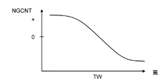
そして、前記判定値NGCNTは、固定値として予め記憶させておくことができる他、冷却水温度TWが高いほど、冷却水異常によってオーバーヒートし易くなるので、冷却水温度TWが高いほどカウント値COUNTがより小さい段階から冷却水異常を判定して、オーバーヒート対策を早期に実施することが好ましいので、図6に示すように、前記判定値NGCNTは、冷却水温度TWが高いほどより小さい値に設定することができる。
The determination value NGCNT is a value for discriminating the value of the count value COUNT into an abnormal range region that is recognized as abnormal cooling water and a normal range region other than that.
The determination value NGCNT can be stored in advance as a fixed value, and the higher the cooling water temperature TW, the more easily overheating occurs due to the cooling water abnormality. Therefore, the count value COUNT increases as the cooling water temperature TW increases. Since it is preferable to determine the cooling water abnormality from a smaller stage and take measures against overheating at an early stage, as shown in FIG. 6, the determination value NGCNT is set to a smaller value as the cooling water temperature TW is higher. be able to.
カウント値COUNTが判定値NGCNT未満である場合は、冷却水温度TWの異常上昇が検出されたとしても、その頻度が低く、そのまま放置してもオーバーヒートに至るようなことはないものと判断し、ステップS107を迂回して本ルーチンを終了させる。
一方、カウント値COUNTが判定値NGCNT以上である場合は、冷却水温度TWの異常上昇が検出された頻度が、何らかの対処を必要とするほど高く、そのまま放置するとオーバーヒートに至る可能性があるものと判断し、ステップS107へ進む。
If the count value COUNT is less than the determination value NGCNT, even if an abnormal increase in the cooling water temperature TW is detected, it is determined that the frequency is low and overheating will not occur if left as it is. Step S107 is bypassed and this routine is terminated.
On the other hand, when the count value COUNT is equal to or greater than the determination value NGCNT, the frequency at which the abnormal rise in the cooling water temperature TW is detected is high enough to require some countermeasure, and if left as it is, there is a possibility of overheating. Judge and proceed to step S107.
換言すれば、前記判定値NGCNTは、冷却水温度TWの異常上昇が検出された頻度(回数)の許容最大値に相当し、カウント値COUNTが判定値NGCNT未満である間は、正常範囲と見なして通常の冷却制御を継続させ、カウント値COUNTが判定値NGCNT以上になって初めて冷却水異常の発生を判断して、後述するように、オーバーヒートの発生を未然に抑制するためのフェイルセーフ処理を実施する。 In other words, the determination value NGCNT corresponds to an allowable maximum value of the frequency (number of times) at which an abnormal increase in the coolant temperature TW is detected, and is regarded as a normal range while the count value COUNT is less than the determination value NGCNT. The normal cooling control is continued, and the occurrence of cooling water abnormality is determined only after the count value COUNT becomes equal to or greater than the determination value NGCNT. As will be described later, a fail-safe process is performed to suppress the occurrence of overheating. carry out.
ステップS107では、冷却系異常の発生を判定し、異常発生の有無を示すフラグfDGNWSYSに、異常状態を示す「1」を設定する。
前記冷却系異常とは、例えば冷却水に空気が混入した冷却水異常であり、冷却水に空気が混入すると、冷却水の循環系内における圧力を高圧側に保てなくなって、冷却水が沸騰し、オーバーヒートが発生する可能性がある。
特に、冷却水の温度を比較的高い温度に保って、エンジン1のフリクションを低下させようとすると、冷却水に空気が混入したときに、オーバーヒートが発生し易くなるため、オーバーヒート対策を直ちに実施することが望まれる。
In step S107, the occurrence of a cooling system abnormality is determined, and “1” indicating an abnormal state is set in a flag fDGNWSYS indicating whether or not the abnormality has occurred.
The cooling system abnormality is, for example, a cooling water abnormality in which air is mixed into the cooling water. When air is mixed into the cooling water, the pressure in the cooling water circulation system cannot be maintained on the high pressure side, and the cooling water boils. And overheating may occur.
In particular, if the temperature of the cooling water is maintained at a relatively high temperature to reduce the friction of the
そこで、フラグfDGNWSYSに「1」が設定されている冷却系異常の状態では、オーバーヒートの発生を未然に抑制すべく、以下に示すフェイルセーフ処理(1)〜(5)のうちの少なくとも1つを実行する。
(1)冷却系異常の発生を運転者に警告する。
具体例:(1-1)オーバーヒートランプ17を点灯する。
(2)冷却ファン(ラジエータファン)5の動作条件を変更する。
具体例:(2-1)冷却系異常時は常時オンにする(ファンの回転速度の最小値を上げる)。
(2-2)動作条件を正常時よりも低水温側に変更する。
(3)電制サーモスタットバルブ10の動作条件を変更する。
具体例:(3-1)動作条件(開弁条件)を正常時よりも低水温側に変更する。
(3-2)異常時は最大通電に固定する。
(4)エンジンの出力(発生熱量)の制限を行う。
具体例:(4-1)最大スロットル開度を低下させる。
(4-2)異常時用の最大エンジン回転速度で燃料カットを行う。
(5)電動式ウォータポンプ8の動作条件を変更する。
具体例:(5-1)最低動作回転速度を上げる(オーバーヒート抑制)。
(5-2)最高動作回転速度を下げる(気泡混入によるポンプ破損の抑制)。
Therefore, in the state of the cooling system abnormality in which “1” is set in the flag fDGNWSYS, at least one of the following fail-safe processes (1) to (5) is performed to suppress the occurrence of overheating. Execute.
(1) The driver is warned of the occurrence of a cooling system abnormality.
Specific example: (1-1) The
(2) The operating condition of the cooling fan (radiator fan) 5 is changed.
Specific example: (2-1) Always turn on when the cooling system is abnormal (increase the minimum value of fan rotation speed).
(2-2) Change the operating condition to a lower water temperature than normal.
(3) The operating condition of the
Specific example: (3-1) Change the operating condition (valve opening condition) to the lower water temperature side than normal.
(3-2) Fix to maximum energization in case of abnormality.
(4) The engine output (heat generation amount) is limited.
Specific example: (4-1) Reduce the maximum throttle opening.
(4-2) Cut the fuel at the maximum engine speed for abnormal conditions.
(5) The operating condition of the
Specific example: (5-1) Raise the minimum operation rotation speed (suppress overheat).
(5-2) Decrease the maximum operating rotation speed (suppression of pump damage caused by air bubbles).
フェイルセーフ処理(1)の運転者への警告は、オーバーヒートが発生する可能性が高くなっていることを運転者に認知させることで、高負荷運転の自制や、整備工場での点検修理を促すと共に、他のフェイルセーフ処理を実行するときに警告を行うことで、運転性の変化が冷却系異常に伴うフェイルセーフ処理に因るものであることを運転者に認知させることができる。
運転者への警告は、車両の運転席近傍に設けたオーバーヒートランプ17の点灯によって行える他、ブザーや文字表示などで異常の発生を警告できる。
The warning to the driver of fail-safe treatment (1) makes the driver aware that the possibility of overheating is high, and encourages self-control of high-load driving and inspection and repair at a maintenance shop At the same time, by giving a warning when executing another fail-safe process, it is possible to make the driver recognize that the change in drivability is due to the fail-safe process associated with the cooling system abnormality.
The warning to the driver can be given by turning on an
フェイルセーフ処理(2)の冷却ファンの動作条件の変更は、冷却ファン5を異常時には正常時よりも低い冷却水温度TWから動作させたり、冷却ファン5の風量(回転速度)を異常時には正常時よりも増加させることで、ラジエータ3における放熱効率(放熱量)を増やし、冷却水の温度上昇を抑制するものである。
The change in the operating condition of the cooling fan in the fail-safe process (2) is that the cooling
フェイルセーフ処理(3)の電制サーモスタットバルブの動作条件の変更は、異常時には正常時よりも低い冷却水温度から、ラジエータ3を介して冷却水を循環させるようにしたり、ラジエータ3を介して循環させる冷却水の流量を異常時には正常時よりも増やすことで、冷却水の温度上昇を抑制するものである。
The operating condition of the electric thermostat valve in the fail-safe process (3) is changed such that the cooling water is circulated through the
フェイルセーフ処理(4)のエンジン出力制限は、エンジンの発熱量が設定量を超えることになる領域での運転を禁止し、発熱量が設定量を下回る領域でエンジン1を運転させることで、エンジン1の冷却水通路2を冷却水が流れるときの受熱量を減らし、冷却水の温度上昇を抑制するものである。換言すれば、フェイルセーフ処理(4)のエンジン出力制限は、エンジンの最大出力を冷却水が正常である場合に比べてより低く制限する処理である。
エンジン出力の制限は、エンジン1の電子制御スロットルにおける最大開度を異常時には正常時に比べて低下させることや、正常時にはエンジン1への燃料噴射が行われる高回転域で異常には燃料カットを行うことなどで実現できる。
The engine output limitation of the failsafe process (4) prohibits operation in a region where the heat generation amount of the engine exceeds the set amount, and causes the
The engine output is limited by reducing the maximum opening of the electronically controlled throttle of the
フェイルセーフ処理(5)の動作条件の変更には、相互に目的が異なる2つのパターンが含まれる。フェイルセーフ処理(5)のうち、電動式ウォータポンプ8の最低動作回転速度を上げる変更は、電動式ウォータポンプ8の吐出量を、異常時には正常時よりも増大させることで、冷却水の循環流量(熱容量)を増やし、冷却水の温度上昇を抑制するものである。
一方、フェイルセーフ処理(5)のうち、電動式ウォータポンプ8の最高動作回転速度を異常時には正常時よりも下げる変更は、正常時には運転が許容される高回転側でのポンプ駆動を禁止し、気泡が混入している冷却水がポンプ内に流入することで、ポンプ主軸に過大な応力が加わることや、キャビテーションによる影響を抑制するものである。
尚、電動式ウォータポンプ8の最高動作回転速度を異常時には正常時よりも下げる変更は、冷却水の温度上昇を抑制する作用はないので、オーバーヒートに至る可能性が低いとき、より具体的には、気泡検知時の冷却水温度が低く、オーバーヒート温度に至るまで余裕代があるときや、他のフェイルセーフ処理の実施によって冷却水温度が低下した後に実施させるようにしてもよい。
The change of the operating condition of the failsafe process (5) includes two patterns having different purposes. In the fail-safe process (5), the change to increase the minimum operating rotational speed of the
On the other hand, in the fail-safe process (5), changing the maximum operating rotational speed of the
In addition, since the change which lowers the maximum operation rotational speed of the
これらのフェイルセーフ処理は、単独で実施しても良いし、複数を組み合わせて実行させてもよい。例えば、運転者に警告した上で、冷却ファン(ラジエータファン)5の動作条件を変更して冷却水温度の上昇を抑え、かつ、電動式ウォータポンプ8の最大動作回転速度を下げることでポンプ保護を図ることができる。
但し、冷却水温度の上昇を抑制する処理、換言すれば、循環系における冷却液の冷却能力を上昇させる処理であるフェイルセーフ処理(2),(3),(4),(5−1)のうちの少なくとも1つを実施し、冷却水の異常状態におけるオーバーヒートの発生を抑制することが好ましい。
These fail safe processes may be performed independently or may be executed in combination. For example, after warning the driver, the operating condition of the cooling fan (radiator fan) 5 is changed to suppress the rise of the cooling water temperature, and the maximum operating rotational speed of the
However, the process which suppresses the raise of a cooling water temperature, ie, the fail safe process (2), (3), (4), (5-1) which is a process which raises the cooling capacity of the cooling fluid in a circulation system. It is preferable to implement at least one of the above and suppress the occurrence of overheating in an abnormal state of the cooling water.
上記のように、電子制御ユニット11によって、冷却水(冷却液)の異常を判定した場合にステップS107で実行されるフェイルセーフ処理、より詳細には、フェイルセーフ処理(2),(3),(4),(5−1)は、循環系における冷却水の冷却能力を上昇させる手段である。
As described above, when the
一方、前記ステップS104で変数DTWNと判定値SLDTWNとの比較によって、異常な温度上昇の発生が検出されなかった場合には、ステップS108へ進む。
ステップS108では、冷却水温度TWが許容最大温度(例えば98℃)未満である正常温度状態であるか否かを判断する。
冷却水温度TWが前記許容最大温度以上であるときに、オーバーヒート状態であると判断できるように、前記許容最大温度を設定してある。
On the other hand, if the occurrence of an abnormal temperature rise is not detected by comparing the variable DTWN with the determination value SLDTTWN in step S104, the process proceeds to step S108.
In step S108, it is determined whether or not the cooling water temperature TW is in a normal temperature state that is lower than the allowable maximum temperature (eg, 98 ° C.).
The allowable maximum temperature is set so that it can be determined that the cooling water temperature TW is equal to or higher than the allowable maximum temperature.
冷却水温度が前記許容最大温度未満であってオーバーヒート状態でない場合には、更に、ステップS109へ進み、カウント値COUNTがカウントアップされない状態、即ち、異常な温度上昇が検出されない状態が、判定時間以上継続しているか否かを判断する。
即ち、ステップS109では、冷却水に対する気泡の混入量がオーバーヒートを発生させるほどに多くなく、係る状態に対応して冷却水温度TWの急な上昇変化が検出される頻度が低い状態であるか否かを判断するものである。
If the cooling water temperature is lower than the allowable maximum temperature and not in the overheat state, the process further proceeds to step S109, and the state where the count value COUNT is not counted up, that is, the state where no abnormal temperature rise is detected is equal to or longer than the determination time. Determine if it is continuing.
That is, in step S109, the amount of bubbles mixed in the cooling water is not so large as to cause overheating, and whether or not the frequency of detecting a sudden rise in the cooling water temperature TW corresponding to such a state is low. It is a judgment.
前記判定時間は、冷却水に対する気泡の混入量がオーバーヒートを発生させるほどに多くない場合に、冷却水温度TWの急な上昇変化が検出される時間間隔に基づき予め設定されていて、前記判定時間だけ急な温度上昇が検出されなかった場合には、冷却水に空気が混入しているとしても、その量がオーバーヒートを発生させるほどの量ではないものと推定できるようにしてある。
そして、カウント値COUNTがカウントアップされない状態が、判定時間以上継続していれば、ステップS110へ進み、冷却系(冷却水)が正常であると判断して、前記フラグfDGNWSYSをゼロにリセットし、また、ステップS107でフェイルセーフ処理を実施していれば、その処理を停止させ、正常時の状態に復帰させる。
The determination time is set in advance based on a time interval at which a sudden change in the cooling water temperature TW is detected when the amount of bubbles mixed into the cooling water is not so large as to cause overheating. If no sudden temperature rise is detected, even if air is mixed in the cooling water, it can be estimated that the amount is not enough to cause overheating.
If the state where the count value COUNT is not counted up continues for the determination time or longer, the process proceeds to step S110, the cooling system (cooling water) is determined to be normal, and the flag fDGNWSYS is reset to zero. If the fail safe process is performed in step S107, the process is stopped and returned to the normal state.
尚、ステップS110へ進んだ場合に、カウント値COUNTを初期値であるゼロにリセットすることができる。
ステップS107で冷却系の異常を判定すると、その後、オーバーヒート状態でなく、かつ、新たに冷却水温度TWの急な上昇変化が検出されない状態が判定時間だけ継続していると判断されるようになるまで、異常判定がキャンセルされずに、フェイルセーフ処理を継続させる。
Note that when the process proceeds to step S110, the count value COUNT can be reset to the initial value of zero.
When the abnormality of the cooling system is determined in step S107, it is determined that the state where the overheating state is not newly detected and the sudden increase in the cooling water temperature TW is not detected is continued for the determination time. Until the failure determination is not canceled, the fail safe process is continued.
また、ステップS108でオーバーヒート状態であると判断しても、冷却水温度TWの急な上昇変化を検出していない状態が継続している場合には、オーバーヒートの原因は気泡混入ではないと推定できるので、ステップS110へ進んで、冷却水異常の判定結果をキャンセルすることができる。但し、この場合、原因が空気の混入でないとしてもオーバーヒート状態であるので、ステップS107で実施したフェイルセーフ処理(循環系における冷却液の冷却能力を上昇させる処理)を継続させることが好ましい。 Further, even if it is determined in step S108 that the state is an overheat state, if a state in which a sudden change in the cooling water temperature TW is not detected is continued, it can be estimated that the cause of the overheat is not a bubble mixture. Therefore, it progresses to step S110 and the determination result of cooling water abnormality can be canceled. However, in this case, it is preferable to continue the fail-safe process (a process for increasing the cooling capacity of the cooling liquid in the circulation system) performed in step S107 because the cause is not air mixing but the overheating state.
ここで、前記ステップS102における判定値SLDTWNの演算処理を、図7のフローチャートに従って詳細に説明する。
前述のように、冷却水温度TWの上昇し易さは、エンジン1の発生熱量、車速VSP、冷却ファン5の動作状態、外気温度などの条件で変化するため、これらの条件に応じて判定値SLDTWNを変更することで、気泡による急な温度上昇の検出精度を高める。
Here, the calculation process of the determination value SLDTWN in step S102 will be described in detail according to the flowchart of FIG.
As described above, the ease of increasing the coolant temperature TW varies depending on conditions such as the amount of heat generated by the
まず、ステップS201では、エンジン発生熱量に応じて判定値SLDTWNの基本値BSLDTWNE#を補正するための係数KENGHET(補正値)を演算する。
エンジン1の発生熱量が大きくなるほど、冷却水温度TWの急な上昇が発生し易くなるため、係るエンジン発熱量による冷却水温度TWの上昇を超える温度上昇を判定させるべく、前記係数KENGHETは、エンジン1の発生熱量が大きくなるほど判定値SLDTWNをより大きな値に補正する。
First, in step S201, a coefficient KENGHET (correction value) for correcting the basic value BSLDTWNE # of the determination value SLDTTWN is calculated according to the amount of heat generated by the engine.
As the amount of heat generated by the
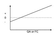
具体的には、図8に示すように、エンジン1の吸入空気流量QA又はエンジン1に供給される燃料流量FCなどのエンジン負荷を示す状態量に応じて係数KENGHETを記憶したテーブルや、図9に示すように、エンジン回転速度NEとエンジン負荷を示すスロットル開度TVOとに対応して係数KENGHETを記憶したマップを予め用意し、これらのテーブルやマップを参照して、そのときのエンジン発生熱量に対応する係数KENGHETを求める。
Specifically, as shown in FIG. 8, a table storing a coefficient KENGHET according to a state quantity indicating an engine load, such as an intake air flow rate QA of the
ここで、エンジン1の吸入空気流量QA又はエンジン1に供給される燃料流量FCが高く、エンジン1の高負荷運転状態であるほど、エンジン1の発生熱量は多くなるので、エンジン1の吸入空気流量QA又はエンジン1に供給される燃料流量FCが高くなるほど、判定値SLDTWNがより高く補正されるように係数KENGHETを設定する。
また、スロットル開度はエンジン1の負荷を表す状態量であり、高負荷(高スロットル開度)でかつ高回転速度である領域でエンジン1の発生熱量が多くなり、低負荷(低スロットル開度)でかつ低回転速度である領域でエンジン1の発生熱量が少なくなる。
Here, as the intake air flow rate QA of the
The throttle opening is a state quantity that represents the load of the
そこで、高負荷でかつ高回転速度である領域で判定値SLDTWNが最も高く補正されるように係数KENGHETを設定し、低負荷でかつ低回転速度である領域で判定値SLDTWNが最も低く補正されるように係数KENGHETを設定する。
尚、テーブルやマップを用いずに、基本値BSLDTWNE#を補正するための係数(補正値)を演算式に従って算出することができる。
Therefore, the coefficient KENGHET is set so that the determination value SLDTTWN is corrected to the highest value in the region where the load is high and the rotation speed is high, and the determination value SLDTWN is corrected to be the lowest in the region where the load is low and the rotation speed is low. The coefficient KENGHET is set as follows.
Note that a coefficient (correction value) for correcting the basic value BSLDTWNE # can be calculated according to an arithmetic expression without using a table or a map.
次のステップS202では、エンジン1を搭載した車両の車速VSPに応じて判定値SLDTWNの基本値BSLDTWNE#を補正するための係数KVSPを演算する。
車速VSPが高くなると、ラジエータ3における放熱効率(放熱量)が高くなり、冷却水温度TWの急な上昇が発生し難くなるので、前記係数KVSPは、車速VSPが高くなるほど、判定値SLDTWNをより小さい値に補正する。
具体的には、図10に示すように、車速VSPに応じて係数KVSPを記憶したテーブルを予め用意し、そのときの車速VSPに対応する係数KVSPを検索する。
In the next step S202, a coefficient KVSP for correcting the basic value BSLDTWNE # of the determination value SLDTTWN is calculated according to the vehicle speed VSP of the vehicle on which the
When the vehicle speed VSP increases, the heat dissipation efficiency (heat dissipation amount) in the
Specifically, as shown in FIG. 10, a table storing the coefficient KVSP according to the vehicle speed VSP is prepared in advance, and the coefficient KVSP corresponding to the vehicle speed VSP at that time is searched.
ステップS203では、冷却ファン(ラジエータファン)5の動作状態に応じて判定値SLDTWNの基本値BSLDTWNE#を補正するための係数KRDFNを演算する。
冷却ファン5の回転速度(駆動量)が高く、ラジエータ3への送風量が多いと、ラジエータ3における放熱効率(放熱量)が高くなり、冷却水温度TWの急な上昇が発生し難くなるので、前記係数KRDFNは、冷却ファン5の回転速度(駆動量)が高くなるほど、判定値SLDTWNをより小さい値に補正する。
具体的には、図11に示すように、冷却ファン5の回転速度(駆動量)に応じて係数KRDFNを記憶したテーブルを予め用意し、そのときの冷却ファン5の回転速度(駆動量)に対応する係数KRDFNを検索する。
In step S203, a coefficient KRDFN for correcting the basic value BSLDTWNE # of the determination value SLDTWN is calculated according to the operating state of the cooling fan (radiator fan) 5.
If the rotational speed (driving amount) of the cooling
Specifically, as shown in FIG. 11, a table storing coefficients KRDFN according to the rotational speed (drive amount) of the cooling
ステップS204では、外気温度TAに応じて判定値SLDTWNの基本値BSLDTWNE#を補正するための係数KTAを演算する。
外気温度TAが高いと、ラジエータ3における放熱効率(放熱量)が低くなり、冷却水温度TAの急な上昇が発生し易くなるので、前記係数KTAは、外気温度TAが高くなるほど、判定値SLDTWNをより大きな値に補正する。
具体的には、図12に示すように、外気温度TAに応じて係数KTAを記憶したテーブルを予め用意し、そのときの外気温度TAに対応する係数KTAを検索する。
In step S204, a coefficient KTA for correcting the basic value BSLDTWNE # of the determination value SLDTTWN is calculated according to the outside air temperature TA.
When the outside air temperature TA is high, the heat radiation efficiency (heat radiation amount) in the
Specifically, as shown in FIG. 12, a table storing the coefficient KTA according to the outside air temperature TA is prepared in advance, and the coefficient KTA corresponding to the outside air temperature TA at that time is searched.
ステップS205では、ステップS201〜ステップS204で求めた係数KENGHET,KVSP,KRDFN,KTAと、予め記憶してある判定値SLDTWNの基本値BSLDTWNE#とから、冷却水温度TAの急な上昇の発生を判定するための判定値SLDTWNを、下式に従って演算する。
SLDTWN=BSLDTWNE#+KENGHET+KVSP+KRDFN+KTA
In step S205, the occurrence of a sudden increase in the coolant temperature TA is determined from the coefficients KENGHET, KVSP, KRDFN, KTA obtained in steps S201 to S204 and the basic value BSLDTWNE # of the determination value SLDTTWN stored in advance. A determination value SLDTTWN for calculating the value is calculated according to the following equation.
SLDTTWN = BSLDTWNE # + KENGHET + KVSP + KRDFN + KTA
前記基本値BSLDTWNE#は、エンジン発生熱量、車速VSP、冷却ファン5の回転速度(駆動量)、外気温度TAがそれぞれ標準状態である場合に適合するように、予め設定されており、前記標準状態からのずれ分を、係数KENGHET,KVSP,KRDFN,KTAによって修正する。
尚、判定値SLDTWNは、エンジン1の発生熱量、車速VSP、冷却ファン5の動作状態、外気温度TAのうちの少なくとも1つに基づいて可変に設定することができ、また、これらの状態量の他、湿度、降水量、高度、冷却液の種類、日照、路面温度などに応じて判定値SLDTWNを可変に設定することができる。
The basic value BSLDTWNE # is set in advance so as to be adapted to the case where the engine generated heat amount, the vehicle speed VSP, the rotation speed (driving amount) of the cooling
Note that the determination value SLDTTWN can be variably set based on at least one of the amount of heat generated by the
上記冷却系の異常診断によると、冷却水温度TWから冷却水(冷却液)に空気が混入した冷却系の異常(冷却水異常)を簡易に検出することができる。
そして、冷却系の異常(冷却水異常)を検出したときに、循環系における冷却水の冷却能力を上昇させるフェイルセーフ処理を実施することで、オーバーヒートの発生を未然に抑制することが可能となる。
According to the cooling system abnormality diagnosis, it is possible to easily detect a cooling system abnormality (cooling water abnormality) in which air is mixed into the cooling water (cooling liquid) from the cooling water temperature TW.
Then, when an abnormality in the cooling system (cooling water abnormality) is detected, it is possible to suppress the occurrence of overheating by performing a fail-safe process that increases the cooling capacity of the cooling water in the circulation system. .
また、冷却系の異常(冷却水異常)を検出したときに、電動式ウォータポンプ8の最高動作回転速度を下げれば、冷却水に空気が混入している状態で高回転でポンプが駆動されてポンプ主軸に過大な応力が加わることを抑制でき、電動式ウォータポンプ8の損傷を未然に抑制できる。
また、冷却水温度TWの急な上昇を判定するための判定値を、エンジン1の発生熱量(エンジン負荷、エンジン回転速度)、車速VSP、冷却ファン5の動作状態、外気温度TAなどの条件に応じて変更すれば、これらの条件が変化しても、冷却水に空気が混入している冷却系の異常を安定して高い精度で判定することができる。
Moreover, if the maximum operating rotational speed of the
Further, the determination value for determining the sudden rise in the coolant temperature TW is set to conditions such as the amount of heat generated by the engine 1 (engine load, engine speed), the vehicle speed VSP, the operating state of the cooling
更に、冷却水温度TWの急な上昇を判定した頻度に基づき、最終的な異常判定を行うので、オーバーヒートを発生させるほどに多くない空気の混入に対して異常判定を行い、無用なフェイルセーフ処理を実施してしまうことを抑制できる。
また、正常判定(異常判定のキャンセル)を、冷却水温度TWと、急な温度上昇を継続して検出していない時間に基づいて行うので、異常継続状態若しくはフェイルセーフ処理が効力を発揮するようになるまでの遅れ時間内で異常判定をキャンセルしてしまうことを抑制できる。
Furthermore, since the final abnormality determination is performed based on the frequency at which the sudden rise in the coolant temperature TW is determined, an abnormality determination is made for air contamination that is not so much as to cause overheating, and unnecessary fail-safe processing is performed. Can be suppressed.
Moreover, since the normal determination (cancellation of the abnormal determination) is performed based on the cooling water temperature TW and the time during which a sudden temperature increase is not continuously detected, the abnormal continuation state or the fail-safe process is effective. It is possible to suppress canceling the abnormality determination within the delay time until the time becomes.
ここで、上記実施形態から把握し得る請求項以外の技術的思想について、以下に効果と共に記載する。
(イ)請求項3記載の内燃機関の冷却装置において、
前記冷却装置が、ラジエータとラジエータファンとを含み、
前記冷却能力制御手段が、冷却液が正常である場合に比べて前記ラジエータファンの風量の増大及び/又は前記ラジエータファンの動作開始温度の低下によって、循環系における冷却液の冷却能力を上昇させる内燃機関の冷却装置。
上記発明によると、冷却液に異常が発生した場合に、ラジエータファンの風量を増大させるか、及び/又は、ラジエータファンをより低い冷却液温度から動作させることで、ラジエータにおける放熱効率(放熱量)を増やし、冷却液の温度上昇を抑制する。
Here, technical ideas other than the claims that can be grasped from the above embodiment will be described together with effects.
(A) In the cooling device for an internal combustion engine according to
The cooling device includes a radiator and a radiator fan;
The internal combustion engine in which the cooling capacity control means increases the cooling capacity of the cooling liquid in the circulation system by increasing the air volume of the radiator fan and / or decreasing the operation start temperature of the radiator fan as compared with the case where the cooling liquid is normal. Engine cooling system.
According to the above invention, when an abnormality occurs in the coolant, the heat dissipation efficiency (heat dissipation amount) in the radiator is increased by increasing the air volume of the radiator fan and / or operating the radiator fan from a lower coolant temperature. Increase the temperature of the coolant.
(ロ)請求項3記載の内燃機関の冷却装置において、
前記冷却装置が、ラジエータと該ラジエータを迂回して冷却液を循環させる電制サーモスタットバルブとを含み、
前記冷却能力制御手段が、前記ラジエータを迂回して冷却液を循環させる条件としての冷却液温度を冷却液が正常である場合に比べて低下させることによって、循環系における冷却液の冷却能力を上昇させる内燃機関の冷却装置。
上記発明によると、正常時よりもより低温からラジエータを介して冷却液を循環させることで、冷却液の温度上昇を抑制する。
(B) In the internal combustion engine cooling device according to
The cooling device includes a radiator and an electric thermostat valve that circulates the coolant around the radiator,
The cooling capacity control means increases the cooling liquid cooling capacity in the circulation system by lowering the cooling liquid temperature as a condition for circulating the cooling liquid bypassing the radiator as compared with the case where the cooling liquid is normal. A cooling device for an internal combustion engine.
According to the said invention, the temperature rise of a cooling fluid is suppressed by circulating a cooling fluid via a radiator from lower temperature than normal.
(ハ)請求項3記載の内燃機関の冷却装置において、
前記冷却能力制御手段が、前記内燃機関の最大出力を、冷却液が正常である場合に比べてより低く制限することによって、循環系における冷却液の冷却能力を上昇させる内燃機関の冷却装置。
上記発明によると、内燃機関の発熱量が設定量を超えることになる領域での運転を禁止し、発熱量が設定量を下回る領域で内燃機関を運転させることで、冷却液に対する内燃機関からの受熱量を減らし、冷却液の温度上昇を抑制する。
(C) The internal combustion engine cooling device according to
The cooling apparatus for an internal combustion engine, wherein the cooling capacity control means limits the maximum output of the internal combustion engine to be lower than that in a case where the cooling liquid is normal, thereby increasing the cooling capacity of the cooling liquid in the circulation system.
According to the above invention, the operation in the region where the heat generation amount of the internal combustion engine exceeds the set amount is prohibited, and the internal combustion engine is operated in the region where the heat generation amount is lower than the set amount, thereby Reduces the amount of heat received and suppresses the temperature rise of the coolant.
(ニ)請求項3記載の内燃機関の冷却装置において、
前記冷却装置が、冷却液を循環させるポンプとして電動式ウォータポンプを含み、
前記冷却能力制御手段が、前記電動式ウォータポンプの吐出量を冷却液が正常である場合に比べて増加させることによって、循環系における冷却液の冷却能力を上昇させる内燃機関の冷却装置。
上記発明によると、電動式ウォータポンプの吐出量を冷却液の正常時よりも増大させることで冷却液の循環流量(熱容量)を増やし、冷却液の温度上昇を抑制する。
(D) In the internal combustion engine cooling device according to
The cooling device includes an electric water pump as a pump for circulating the coolant,
A cooling apparatus for an internal combustion engine, wherein the cooling capacity control means increases the cooling capacity of the cooling liquid in the circulation system by increasing the discharge amount of the electric water pump as compared with a case where the cooling liquid is normal.
According to the above invention, the circulation rate (heat capacity) of the cooling liquid is increased by increasing the discharge amount of the electric water pump as compared with the normal time of the cooling liquid, and the temperature rise of the cooling liquid is suppressed.
(ホ)請求項1〜3のいずれか1つに記載の内燃機関の冷却装置において、
前記冷却装置が、冷却液を循環させるポンプとして電動式ウォータポンプを含み、
前記異常判定手段が、冷却液の異常の発生を判定した場合に、前記電動式ウォータポンプの最高動作回転速度を下げる最高回転低下手段を備える内燃機関の冷却装置。
上記発明によると、冷却液の異常の発生を判定した場合に電動式ウォータポンプの最高動作回転速度を下げることで、空気が混入している冷却液が流入する状態で高回転でポンプが駆動され、ポンプの主軸に過大な応力が加わって損傷することを抑制できる。
(E) In the cooling device for an internal combustion engine according to any one of
The cooling device includes an electric water pump as a pump for circulating the coolant,
A cooling apparatus for an internal combustion engine, comprising: a maximum rotation reduction means for decreasing a maximum operating rotational speed of the electric water pump when the abnormality determination means determines that an abnormality of the coolant has occurred.
According to the above invention, the pump is driven at a high speed in a state where the cooling liquid in which air is mixed flows in by reducing the maximum operating rotational speed of the electric water pump when it is determined that the abnormality of the cooling liquid has occurred. Further, it is possible to suppress damage caused by applying excessive stress to the main shaft of the pump.
(ヘ)請求項2記載の内燃機関の冷却装置において、
前記判定値を、内燃機関の発生熱量、内燃機関を搭載した車両の走行速度、ラジエータファンの動作状態、外気温度のうちの少なくとも1つに基づいて可変に設定する判定値設定手段を備えた内燃機関の冷却装置。
上記発明によると、冷却液温度の上昇し易さは、内燃機関の発生熱量、車速、ラジエータファンの動作状態、外気温度などの条件で変化するため、これらの条件に応じて判定値を変更することで、気泡による急な温度上昇の検出精度を高める。
(F) The internal combustion engine cooling device according to
An internal combustion engine comprising: a determination value setting unit configured to variably set the determination value based on at least one of an amount of heat generated by the internal combustion engine, a traveling speed of a vehicle equipped with the internal combustion engine, an operating state of a radiator fan, and an outside air temperature. Engine cooling system.
According to the above invention, the ease with which the coolant temperature rises varies depending on conditions such as the amount of heat generated by the internal combustion engine, the vehicle speed, the operating state of the radiator fan, the outside air temperature, etc., and therefore the determination value is changed according to these conditions. In this way, the detection accuracy of a sudden temperature rise due to bubbles is increased.
(ト)請求項2記載の内燃機関の冷却装置において、
前記異常判定手段が、冷却液の温度が判定値を超える急な上昇変化を示した回数を計数し、当該計数値が判定回数を超えた場合に、冷却液の異常の発生を判定する内燃機関の冷却装置。
上記発明によると、冷却液に対する空気の混入量(気泡量)が少なく、冷却液の温度が急に上昇する頻度が少ない場合には、冷却液の異常と判定せずに、冷却液に対する空気の混入量(気泡量)がオーバーヒートの可能性がある程度に多く、冷却液の温度が急に上昇する頻度が多い場合には、冷却液の異常の発生を判定することで、対策が必要な空気の混入(冷却液の異常)を精度良く判定する。
(G) In the internal combustion engine cooling device according to
An internal combustion engine in which the abnormality determination means counts the number of times that the temperature of the coolant has shown a sudden rise change exceeding the determination value, and determines the occurrence of abnormality of the coolant when the count value exceeds the determination number Cooling system.
According to the above invention, when the amount of air mixed into the cooling liquid (the amount of bubbles) is small and the temperature of the cooling liquid suddenly rises less frequently, it is not determined that the cooling liquid is abnormal. When the amount of contamination (bubbles) is likely to be overheated to a certain extent and the temperature of the cooling liquid suddenly rises frequently, the occurrence of an abnormality in the cooling liquid can be determined to determine the amount of air that needs countermeasures. Determine contamination (coolant abnormality) with high accuracy.
(チ)請求項(ト)記載の内燃機関の冷却装置において、
前記異常判定手段が、前記判定回数を冷却液の温度が高いほどより低く変更する内燃機関の冷却装置。
上記発明によると、冷却液温度が高いほど、冷却液異常によってオーバーヒートし易くなるので、冷却液温度が高いほど、判定回数がより少ない段階から冷却液異常を判定して、オーバーヒート対策を早期に実施することができるようにする。
(H) In the cooling device for an internal combustion engine according to claim (g),
The cooling apparatus for an internal combustion engine, wherein the abnormality determination unit changes the determination frequency lower as the coolant temperature is higher.
According to the above invention, the higher the coolant temperature, the easier it is to overheat due to the coolant abnormality, so the higher the coolant temperature, the coolant abnormality is judged from the stage where the number of judgments is smaller, and the overheat countermeasure is implemented early. To be able to.
1…エンジン(内燃機関)、2…冷却水通路、3…ラジエータ、4…冷却水配管、5…冷却ファン、6…冷却水配管、7…機械式ウォータポンプ、8…電動式ウォータポンプ、9…バイパス配管、10…電制サーモスタットバルブ、11…電子制御ユニット(異常判定手段、冷却能力制御手段)、12…水温センサ(温度検出手段)、13…車速センサ、14…負荷センサ、15…回転センサ、16…外気温センサ
DESCRIPTION OF
Claims (3)
前記冷却液の温度を検出する温度検出手段と、
前記温度検出手段が検出した冷却液の温度の変化に基づき、冷却液の異常の有無を判定する異常判定手段と、
を含む内燃機関の冷却装置。 A cooling device that circulates a coolant to cool an internal combustion engine,
Temperature detecting means for detecting the temperature of the coolant;
An abnormality determining means for determining the presence or absence of an abnormality of the coolant based on a change in the temperature of the coolant detected by the temperature detecting means;
A cooling device for an internal combustion engine including
Priority Applications (1)
| Application Number | Priority Date | Filing Date | Title |
|---|---|---|---|
| JP2011039262A JP5641975B2 (en) | 2011-02-25 | 2011-02-25 | Cooling device for internal combustion engine |
Applications Claiming Priority (1)
| Application Number | Priority Date | Filing Date | Title |
|---|---|---|---|
| JP2011039262A JP5641975B2 (en) | 2011-02-25 | 2011-02-25 | Cooling device for internal combustion engine |
Publications (2)
| Publication Number | Publication Date |
|---|---|
| JP2012177308A true JP2012177308A (en) | 2012-09-13 |
| JP5641975B2 JP5641975B2 (en) | 2014-12-17 |
Family
ID=46979307
Family Applications (1)
| Application Number | Title | Priority Date | Filing Date |
|---|---|---|---|
| JP2011039262A Active JP5641975B2 (en) | 2011-02-25 | 2011-02-25 | Cooling device for internal combustion engine |
Country Status (1)
| Country | Link |
|---|---|
| JP (1) | JP5641975B2 (en) |
Cited By (8)
| Publication number | Priority date | Publication date | Assignee | Title |
|---|---|---|---|---|
| JP2014196671A (en) * | 2013-03-29 | 2014-10-16 | ダイハツ工業株式会社 | Control device for internal combustion engine |
| WO2014174549A1 (en) * | 2013-04-23 | 2014-10-30 | 株式会社Tbk | Fluid supply device |
| CN113217199A (en) * | 2021-04-16 | 2021-08-06 | 联合汽车电子有限公司 | Engine allowed stop judging method and vehicle |
| JP2021131035A (en) * | 2020-02-18 | 2021-09-09 | いすゞ自動車株式会社 | Diagnostic system for cooling circuit |
| CN113465935A (en) * | 2020-03-31 | 2021-10-01 | 比亚迪股份有限公司 | Vehicle cooling circuit detection method and device, computer equipment and storage medium |
| CN114046200A (en) * | 2021-11-09 | 2022-02-15 | 上海柴油机股份有限公司 | Anti-overheating cooling system of hybrid power engine and control method thereof |
| CN114320564A (en) * | 2022-01-19 | 2022-04-12 | 上海世德子汽车零部件有限公司 | Engine coolant delivery control method and system |
| CN115773174A (en) * | 2022-11-26 | 2023-03-10 | 重庆长安汽车股份有限公司 | Control method and system for electronic water pump of engine |
Citations (7)
| Publication number | Priority date | Publication date | Assignee | Title |
|---|---|---|---|---|
| JPH11173691A (en) * | 1997-12-15 | 1999-07-02 | Daikin Ind Ltd | Superconductive magnet cooling device |
| JP2003506616A (en) * | 1999-08-05 | 2003-02-18 | 日本サーモスタット株式会社 | Cooling control system for internal combustion engine |
| JP2003227337A (en) * | 2002-02-01 | 2003-08-15 | Hitachi Ltd | Temperature estimating device for cooling system |
| JP2003269174A (en) * | 2002-03-14 | 2003-09-25 | Sanyo Electric Co Ltd | Air conditioning device |
| JP2009127478A (en) * | 2007-11-21 | 2009-06-11 | Toyota Motor Corp | Vehicle cooling control device and cooling control method |
| JP2009197616A (en) * | 2008-02-19 | 2009-09-03 | Fujitsu Ten Ltd | Cooling system, cooling control device, and flow rate control method |
| JP2010025535A (en) * | 2008-06-17 | 2010-02-04 | Panasonic Corp | Refrigerator |
-
2011
- 2011-02-25 JP JP2011039262A patent/JP5641975B2/en active Active
Patent Citations (7)
| Publication number | Priority date | Publication date | Assignee | Title |
|---|---|---|---|---|
| JPH11173691A (en) * | 1997-12-15 | 1999-07-02 | Daikin Ind Ltd | Superconductive magnet cooling device |
| JP2003506616A (en) * | 1999-08-05 | 2003-02-18 | 日本サーモスタット株式会社 | Cooling control system for internal combustion engine |
| JP2003227337A (en) * | 2002-02-01 | 2003-08-15 | Hitachi Ltd | Temperature estimating device for cooling system |
| JP2003269174A (en) * | 2002-03-14 | 2003-09-25 | Sanyo Electric Co Ltd | Air conditioning device |
| JP2009127478A (en) * | 2007-11-21 | 2009-06-11 | Toyota Motor Corp | Vehicle cooling control device and cooling control method |
| JP2009197616A (en) * | 2008-02-19 | 2009-09-03 | Fujitsu Ten Ltd | Cooling system, cooling control device, and flow rate control method |
| JP2010025535A (en) * | 2008-06-17 | 2010-02-04 | Panasonic Corp | Refrigerator |
Cited By (13)
| Publication number | Priority date | Publication date | Assignee | Title |
|---|---|---|---|---|
| JP2014196671A (en) * | 2013-03-29 | 2014-10-16 | ダイハツ工業株式会社 | Control device for internal combustion engine |
| WO2014174549A1 (en) * | 2013-04-23 | 2014-10-30 | 株式会社Tbk | Fluid supply device |
| US10012227B2 (en) | 2013-04-23 | 2018-07-03 | Tbk Co., Ltd. | Fluid supply device |
| JP7283414B2 (en) | 2020-02-18 | 2023-05-30 | いすゞ自動車株式会社 | Cooling circuit diagnostic device |
| JP2021131035A (en) * | 2020-02-18 | 2021-09-09 | いすゞ自動車株式会社 | Diagnostic system for cooling circuit |
| CN113465935A (en) * | 2020-03-31 | 2021-10-01 | 比亚迪股份有限公司 | Vehicle cooling circuit detection method and device, computer equipment and storage medium |
| CN113465935B (en) * | 2020-03-31 | 2023-09-05 | 比亚迪股份有限公司 | Method and device for detecting cooling circuit of vehicle, computer equipment and storage medium |
| CN113217199A (en) * | 2021-04-16 | 2021-08-06 | 联合汽车电子有限公司 | Engine allowed stop judging method and vehicle |
| CN114046200A (en) * | 2021-11-09 | 2022-02-15 | 上海柴油机股份有限公司 | Anti-overheating cooling system of hybrid power engine and control method thereof |
| CN114046200B (en) * | 2021-11-09 | 2023-02-17 | 上海新动力汽车科技股份有限公司 | Anti-overheating cooling system of hybrid power engine and control method thereof |
| CN114320564A (en) * | 2022-01-19 | 2022-04-12 | 上海世德子汽车零部件有限公司 | Engine coolant delivery control method and system |
| CN115773174A (en) * | 2022-11-26 | 2023-03-10 | 重庆长安汽车股份有限公司 | Control method and system for electronic water pump of engine |
| CN115773174B (en) * | 2022-11-26 | 2024-03-29 | 重庆长安汽车股份有限公司 | Control method and system of electronic water pump of engine |
Also Published As
| Publication number | Publication date |
|---|---|
| JP5641975B2 (en) | 2014-12-17 |
Similar Documents
| Publication | Publication Date | Title |
|---|---|---|
| JP5641975B2 (en) | Cooling device for internal combustion engine | |
| US9341106B2 (en) | Cooling apparatus for engine system and control method therefor | |
| US9695736B2 (en) | Cooling device for internal combustion engine and failure diagnosis method for cooling device for internal combustion engine | |
| JP6148787B2 (en) | Control device for internal combustion engine and control method for cooling device | |
| RU2618740C1 (en) | Cooling device for internal combustion engines and cooling method for internal combustion engines | |
| JP2007270661A (en) | Device for determining abnormality of thermostat | |
| JP2006291815A (en) | Abnormality determination device of turbocharger | |
| CN110671187B (en) | Cooling control method, control device and control system for engine in vehicle | |
| JP2015059458A (en) | Control device for cooling system | |
| JP2008144719A (en) | Throttle valve control device for internal combustion engine | |
| US9170570B2 (en) | Cooling apparatus for internal combustion engine | |
| US10060332B2 (en) | Cooling apparatus for internal combustion engine | |
| JPH11117799A (en) | Failure detector for engine cooling system | |
| JP2015081566A (en) | Cooling device for internal combustion engine | |
| JP2015132229A (en) | vehicle | |
| JP6040908B2 (en) | vehicle | |
| JP5878052B2 (en) | Engine control device | |
| JP2013100724A (en) | Cooling device and cooling method of internal combustion engine | |
| JP2014225142A (en) | Fault diagnosis apparatus | |
| JP7188339B2 (en) | Fan belt abnormality detector | |
| CN115013174B (en) | Control method of EGR (exhaust gas Recirculation) system, EGR system and vehicle | |
| JP7140055B2 (en) | internal combustion engine | |
| JP6443325B2 (en) | Control device for internal combustion engine | |
| JP5206696B2 (en) | Internal combustion engine cooling system | |
| WO2011135680A1 (en) | Electric water pump control device and electric water pump control method |
Legal Events
| Date | Code | Title | Description |
|---|---|---|---|
| A621 | Written request for application examination |
Free format text: JAPANESE INTERMEDIATE CODE: A621 Effective date: 20130215 |
|
| A131 | Notification of reasons for refusal |
Free format text: JAPANESE INTERMEDIATE CODE: A131 Effective date: 20131210 |
|
| A521 | Request for written amendment filed |
Free format text: JAPANESE INTERMEDIATE CODE: A523 Effective date: 20140122 |
|
| A131 | Notification of reasons for refusal |
Free format text: JAPANESE INTERMEDIATE CODE: A131 Effective date: 20140415 |
|
| RD03 | Notification of appointment of power of attorney |
Free format text: JAPANESE INTERMEDIATE CODE: A7423 Effective date: 20140528 |
|
| A521 | Request for written amendment filed |
Free format text: JAPANESE INTERMEDIATE CODE: A523 Effective date: 20140529 |
|
| A02 | Decision of refusal |
Free format text: JAPANESE INTERMEDIATE CODE: A02 Effective date: 20140624 |
|
| A521 | Request for written amendment filed |
Free format text: JAPANESE INTERMEDIATE CODE: A523 Effective date: 20140922 |
|
| A911 | Transfer to examiner for re-examination before appeal (zenchi) |
Free format text: JAPANESE INTERMEDIATE CODE: A911 Effective date: 20140930 |
|
| TRDD | Decision of grant or rejection written | ||
| A01 | Written decision to grant a patent or to grant a registration (utility model) |
Free format text: JAPANESE INTERMEDIATE CODE: A01 Effective date: 20141028 |
|
| A61 | First payment of annual fees (during grant procedure) |
Free format text: JAPANESE INTERMEDIATE CODE: A61 Effective date: 20141028 |
|
| R150 | Certificate of patent or registration of utility model |
Ref document number: 5641975 Country of ref document: JP Free format text: JAPANESE INTERMEDIATE CODE: R150 |
|
| R250 | Receipt of annual fees |
Free format text: JAPANESE INTERMEDIATE CODE: R250 |
|
| R250 | Receipt of annual fees |
Free format text: JAPANESE INTERMEDIATE CODE: R250 |
|
| R250 | Receipt of annual fees |
Free format text: JAPANESE INTERMEDIATE CODE: R250 |
|
| R250 | Receipt of annual fees |
Free format text: JAPANESE INTERMEDIATE CODE: R250 |
|
| S533 | Written request for registration of change of name |
Free format text: JAPANESE INTERMEDIATE CODE: R313533 |
|
| R350 | Written notification of registration of transfer |
Free format text: JAPANESE INTERMEDIATE CODE: R350 |
|
| R250 | Receipt of annual fees |
Free format text: JAPANESE INTERMEDIATE CODE: R250 |
|
| R250 | Receipt of annual fees |
Free format text: JAPANESE INTERMEDIATE CODE: R250 |