JP2012177295A - Method and system for supporting arrangement of constituent members in civil engineering - Google Patents
Method and system for supporting arrangement of constituent members in civil engineering Download PDFInfo
- Publication number
- JP2012177295A JP2012177295A JP2012038317A JP2012038317A JP2012177295A JP 2012177295 A JP2012177295 A JP 2012177295A JP 2012038317 A JP2012038317 A JP 2012038317A JP 2012038317 A JP2012038317 A JP 2012038317A JP 2012177295 A JP2012177295 A JP 2012177295A
- Authority
- JP
- Japan
- Prior art keywords
- component
- directionality
- sensor
- components
- axes
- Prior art date
- Legal status (The legal status is an assumption and is not a legal conclusion. Google has not performed a legal analysis and makes no representation as to the accuracy of the status listed.)
- Pending
Links
Images

Classifications
-
- E—FIXED CONSTRUCTIONS
- E04—BUILDING
- E04G—SCAFFOLDING; FORMS; SHUTTERING; BUILDING IMPLEMENTS OR AIDS, OR THEIR USE; HANDLING BUILDING MATERIALS ON THE SITE; REPAIRING, BREAKING-UP OR OTHER WORK ON EXISTING BUILDINGS
- E04G21/00—Preparing, conveying, or working-up building materials or building elements in situ; Other devices or measures for constructional work
- E04G21/14—Conveying or assembling building elements
- E04G21/16—Tools or apparatus
- E04G21/22—Tools or apparatus for setting building elements with mortar, e.g. bricklaying machines
-
- G—PHYSICS
- G01—MEASURING; TESTING
- G01C—MEASURING DISTANCES, LEVELS OR BEARINGS; SURVEYING; NAVIGATION; GYROSCOPIC INSTRUMENTS; PHOTOGRAMMETRY OR VIDEOGRAMMETRY
- G01C9/00—Measuring inclination, e.g. by clinometers, by levels
- G01C9/02—Details
- G01C9/06—Electric or photoelectric indication or reading means
-
- Y—GENERAL TAGGING OF NEW TECHNOLOGICAL DEVELOPMENTS; GENERAL TAGGING OF CROSS-SECTIONAL TECHNOLOGIES SPANNING OVER SEVERAL SECTIONS OF THE IPC; TECHNICAL SUBJECTS COVERED BY FORMER USPC CROSS-REFERENCE ART COLLECTIONS [XRACs] AND DIGESTS
- Y10—TECHNICAL SUBJECTS COVERED BY FORMER USPC
- Y10T—TECHNICAL SUBJECTS COVERED BY FORMER US CLASSIFICATION
- Y10T29/00—Metal working
- Y10T29/49—Method of mechanical manufacture
- Y10T29/49616—Structural member making
Landscapes
- Engineering & Computer Science (AREA)
- Architecture (AREA)
- General Physics & Mathematics (AREA)
- Civil Engineering (AREA)
- Structural Engineering (AREA)
- Physics & Mathematics (AREA)
- Mechanical Engineering (AREA)
- Radar, Positioning & Navigation (AREA)
- Remote Sensing (AREA)
- Management, Administration, Business Operations System, And Electronic Commerce (AREA)
- Length Measuring Devices With Unspecified Measuring Means (AREA)
- Conveying And Assembling Of Building Elements In Situ (AREA)
- Manipulator (AREA)
- Bridges Or Land Bridges (AREA)
Abstract
Description
本発明は、土木工事における構成材の配置を支援する方法、及びそのシステムに関する。 The present invention relates to a method and a system for supporting arrangement of components in civil engineering work.
土木工事において、構成材を配置し、互いに結合することは周知である。 In civil engineering work, it is well known to arrange components and bond them together.
「土木工事」とは、人間による、壁、橋、道路、パイプラインなどの建設を意味する。 “Civil engineering” means the construction of walls, bridges, roads, pipelines, etc. by humans.
「構成材」とは、互いに結合して、土木工事を実施する建築要素のことを意味する。通常、構成材は、構造上、すべて同一である。従って構成材は、建設の際には、それぞれの方向性と位置においてのみ、互いに異なっている。 “Constituent material” means a building element that is combined with each other to perform civil engineering work. In general, the constituent materials are all the same in structure. Therefore, the components differ from each other only in the direction and position in construction.
土木工事の際、構成材は、正確な位置に配置しなくてはならない。 During civil engineering work, the components must be placed in the correct positions.
この目的のため、土木工事において、構成材の配置を支援する方法について、本願出願人は熟知している。例えば、公知の方法においては、方向性設定値と、構成材の方向性測定値との間の不一致の関数として、各構成材の方向性を調整する。構成材の「方向性」とは、「姿勢」と同じ意味である。 For this purpose, the applicant of the present invention is well aware of a method for supporting the arrangement of components in civil engineering work. For example, in a known method, the directionality of each constituent material is adjusted as a function of a mismatch between the directionality setting value and the directionality measurement value of the constituent material. “Directionality” of a component has the same meaning as “attitude”.
通常、方向性は、構成材の外面に水準器を置くことにより測定される。その後、所望の配置がなされるまで、水準器により読み取られた測定値の関数として、構成材の方向性は調整される。 Usually, directionality is measured by placing a level on the outer surface of the component. Thereafter, the orientation of the component is adjusted as a function of the measured value read by the level until the desired placement is achieved.
所定の計画に、検知器の内容が一致するように、測定と調整は、特別な注意力を払って、行わなくてはならない。 Measurements and adjustments must be made with special care so that the contents of the detector match a predetermined plan.
しかし、構成材を正確に配置するには、時間がかかり、工事を遅らせる。またこのような配置方法によると、人為的なミスを引き起こしやすい。 However, accurate placement of the components takes time and delays construction. In addition, such an arrangement method tends to cause human error.
公知の技術としては、他に特許文献1他に開示されているものがある。
Other known techniques include those disclosed in
本発明は、このような欠点を克服することを目的とし、構成材の方向性測定値と方向性設定値との間の不一致の関数として、構成材の方向性を調整することを含む、土木工事において、構成材の配置を支援する方法であって、
各構成材が、構成材に対して、自由度なしに固定された、少なくとも1つのセンサを備え、同一平面上にない、3本の軸に対する構成材の傾きを測定可能であり、
各構成材の方向性を調整する段階は、方向性設定値と、構成材に固定された方向性センサによる方向性測定値との間の、不一致の関数として実行されることを特徴とする方法を提供するものである。
The present invention aims to overcome such drawbacks and includes adjusting the directionality of a component as a function of the discrepancy between the directionality measurement of the component and the directionality setting. A method for supporting the arrangement of components in construction,
Each component has at least one sensor fixed to the component without any degree of freedom, and can measure the inclination of the component relative to three axes that are not on the same plane,
The method of adjusting the directionality of each component is performed as a function of a mismatch between a directionality set value and a directionality measurement value by a directionality sensor fixed to the component Is to provide.
本発明の方法は、方向性測定値と方向性設定値との間の不一致を確かめるべく、構成材の上に、現場において、水準器若しくは他の方向性センサを置く必要がないので、土木工事は簡単となる。 The method of the present invention eliminates the need to place a level or other directional sensor on-site on the component to ascertain any discrepancies between directional measurements and directional setpoints. Is easy.
上記の方法は、構成材自体に水準器の機能があるので、構成材を容易かつ敏速に配置することが出来る。 In the above method, since the component itself has the function of a level, the component can be easily and quickly arranged.
本発明による実施態様によれば、上記の方法は、
配置された構成材を認識する段階と,
いくつかの方向性設定値を含む表で、認識された構成材の関数として、方向性設定値を選定する段階と、
認識された構成材の方向性測定値と、選択された設定値との間の不一致を指摘する段階とを含み、
位置を調整する段階が、前記不一致の関数として、構成材を取り扱うロボットにより、自動的になされるようになっている。
According to an embodiment according to the invention, the above method comprises:
Recognizing placed components, and
Selecting a directionality setting as a function of a recognized component in a table containing several directionality settings;
Indicating the discrepancy between the recognized directionality measurement of the component and the selected setpoint,
The step of adjusting the position is automatically performed by the robot handling the component as a function of the discrepancy.
本発明によるこの実施態様によると、配置された構成材の関数として、方向性設定値と位置設定値を変えることにより、手による作業が省かれるという利点が得られる。 According to this embodiment according to the invention, the advantage is obtained that the work by hand is eliminated by changing the directionality setting value and the position setting value as a function of the arranged components.
本発明によれば、また、建築物を構築するべく、並べて配置された構成材と、
同一平面上にない、3本の軸に対し、構成材の傾きを測定可能な、少なくとも1本の方向性センサとを備える、土木工事の構成材の配置を支援するシステムにおいて、
各構成材は、この構成材に対し、自由度なしに、固定された少なくとも1つの方向性センサを備え、同一平面上にない、3本の軸に対して、構成材の傾きを測定することが可能であり、かつ構成材のいずれか1つの方向性センサによる方向性測定値と、構成材の方向性設定値との間の、不一致を指摘することが可能な電子的発信装置を備えることを特徴とするシステムが提供される。
According to the present invention, in addition, in order to construct a building,
In a system that supports the arrangement of components for civil engineering work, comprising at least one directional sensor capable of measuring the inclination of the components with respect to three axes that are not on the same plane,
Each component shall have at least one directional sensor fixed without any degree of freedom relative to this component, and measure the inclination of the component with respect to three axes which are not on the same plane. And an electronic transmission device capable of pointing out a discrepancy between the directionality measurement value by any one directionality sensor of the constituent material and the directionality setting value of the constituent material. Is provided.
本発明によるシステムの実施態様においては、以下の特徴の1つ以上を備えている。
(1)発信装置は、構成材から機械的に独立し、かつ、
−人・機械インターフェースと、
−構成材に固定された方向性センサによる方向性測定値と、構成材の方向性設定値との間の不一致を直接人間に理解可能に指摘するように、人・機械インターフェースを制御すべく、プログラミングされた少なくとも1つの電子計算機とを備え、
(2)地面に結合された座標系における、3本の、同一平面にない軸に沿って、構成材の座標を測定することが可能な位置センサと、構成材のいずれか1つの位置センサによる位置測定値と、構成材の位置設定値との間の不一致をも指摘可能な発信装置とを備えている。
Implementations of the system according to the invention include one or more of the following features.
(1) The transmitting device is mechanically independent from the components, and
-Man-machine interface,
-To control the human / machine interface so as to point out the discrepancy between the directionality measured by the directionality sensor fixed to the component and the directionality setting value of the component so that it can be directly understood by humans With at least one programmed electronic calculator,
(2) In a coordinate system coupled to the ground, by means of a position sensor capable of measuring the coordinates of a component along three non-coplanar axes, and any one of the position sensors of the component The transmitter includes a transmitter that can point out a discrepancy between the position measurement value and the position setting value of the component.
このようなシステムの実施態様は、位置センサを使用すると、地上に連結された座標系における構成材の位置決めが容易になるという利点を備えている。 Such a system embodiment has the advantage that the use of position sensors facilitates the positioning of components in a coordinate system coupled to the ground.
また本発明の目的は、上記のシステムにおける構成材を提供することにもある。 Another object of the present invention is to provide a component in the above system.
本発明による構成材の実施態様は、以下の特徴の1つ以上を備えている。
(1)方向性センサが、同一平面上にない3本の軸に沿って、重力場の強度を測定することが可能な3軸加速度計と、同一平面上にはない3本の軸に沿って、地球磁場の強度を測定可能な3軸磁力計とを備えている。
(2)位置センサは、ジャイロメータを備え、このジャイロメータは、構成材に自由度なしに固定され、同一平面上にない3本の測定軸回りの構成材の回転角速度を測定することが可能である。
(3)構成材は、位置センサを備え、この位置センサは、地上に連結された座標系において、同一平面上にはない、3本の軸に沿って、構成材の座標を測定可能である。
(4)方向性センサは、構成材の内部に埋め込まれていて、構成材の外面と同一面にはなく、かつ、外面からも突出していない。
(5)構成材は、レンガ、砕石、導管、梁及びプレートよりなる群から選択される。
Embodiments of the component according to the present invention include one or more of the following features.
(1) A directional sensor that can measure the strength of the gravitational field along three axes that are not on the same plane, and three axes that are not on the same plane And a three-axis magnetometer capable of measuring the intensity of the earth's magnetic field.
(2) The position sensor is equipped with a gyrometer. This gyrometer is fixed to the component without any degree of freedom, and can measure the rotational angular velocities of the components around three measurement axes that are not on the same plane. It is.
(3) The constituent material includes a position sensor, and the position sensor can measure the coordinates of the constituent material along three axes that are not on the same plane in a coordinate system connected to the ground. .
(4) The direction sensor is embedded in the constituent material, is not flush with the outer surface of the constituent material, and does not protrude from the outer surface.
(5) The component is selected from the group consisting of brick, crushed stone, conduit, beam and plate.
本発明の実施態様は、次のような利点を有する。
(1)3軸加速度計とともに、3軸磁力計を使用すると、構成材の近傍で、磁性材により引き起こされる乱れを防ぐことが出来る。
(2)3軸加速度計とともに、3軸ジャイロメーターを使用すると、構成材が動いている時にも、方向性を確実に測定出来る。
(3)構成材内部に位置センサを組み込み、構成材の位置を正確に把握しうるようになっている。
(4)位置センサを構成材の内部に埋め込み、センサを保護しうるようになっている。
Embodiments of the present invention have the following advantages.
(1) When a 3-axis magnetometer is used together with a 3-axis accelerometer, disturbance caused by the magnetic material can be prevented in the vicinity of the constituent material.
(2) When a 3-axis gyrometer is used together with a 3-axis accelerometer, directionality can be reliably measured even when the component is moving.
(3) A position sensor is incorporated inside the component so that the position of the component can be accurately grasped.
(4) A position sensor can be embedded in the component to protect the sensor.
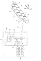
図1は、土木工事の構成材の位置決めを支援するシステム2を示している。図1において、土木工事の対象は、壁4である。
FIG. 1 shows a
構成材6を互いに積み上げることにより、壁4が形成される。この実施態様において、構成材6は同一の形状である。構成材6は、例えば同一の寸法のレンガである。
The walls 4 are formed by stacking the
壁4において、構成材6は、セメントのような結合剤で互いに結合される。
In the wall 4, the
システム2は、構成材6と発信装置10よりなっている。
The
各構成材6は、測定可能なモジュール12を備えている。特に、このモジュール12は、地面における座標系R0におけるモジュール12の位置を測定可能になっている。座標系R0は、3本の軸X0,Y0,Z0を備えている。これら3本の軸X0,Y0,Z0は、同一平面や同一直線上にはなく、互いに直交している。軸Z0は、垂直方向に設けられ、重力場に平行である。
Each
測定された種々の物理的性質を、無線送信14を介して、モジュール12から発信装置10に送信することが出来る。
Various measured physical properties can be transmitted from the
この無線送信は、電磁波を、振幅変調(AM)若しくは周波数変換(FM)により送信する。 In this wireless transmission, electromagnetic waves are transmitted by amplitude modulation (AM) or frequency conversion (FM).
発信装置10は、座標系R0における構成材の座標x0,y0,z0を測定可能な位置センサ20を備えている。センサ20は、モジュール12により発信された電磁波に基づき、座標x0,y0,z0を決定する。対象から発信された電磁波に基づき、対象を配置することが可能な位置センサは公知である。例えば、このような位置センサは、非特許文献1に記載されている。
The transmitting
センサ20は、例えば複数のアンテナを備えており、三角法により、構成材6の位置を決定するようになっている。電磁波の到着時間及び到着角度を利用するとよい。
The
位置センサの機能を実行する他に、モジュール12により実施され、無線送信14を介して、発信装置10に送られる、測定受信機としての機能を有している。
In addition to performing the function of the position sensor, it has a function as a measurement receiver implemented by the
発信装置10は、表36を備えるメモリ22の機能を有している。図1において、表36は、メモリ22に詳細に示されている。例えば、テーブル36には、構成材の識別子iとともに、方向性設定値Coi及び位置設定値Cpiが示されている。ここで、識別子iは、構成材6の順序を示す通し番号である。表36には、第1構成材6の各設定値Co1及びCp1が示されている。次に、壁4を構成する第2構成材6の設定値Co2及びCp2が示されている。このように、表36は、構成材6の位置の順序を示すとともに、方向性と位置を示す。壁の建築計画に基づき、表36が作られる。図1の表36中の記号「・」は、この表のすべての列の一部が省略されていることを示している。
The transmitting
メモリ22とセンサ20に、プログラム可能な電子式計算機38が接続されている。この計算機38は、情報記録媒体に記録された指令を実行する。このために、メモリ22は、図3の方法を実施するのに必要な指令を備えている。
A programmable
計算機38は、人・機械インターフェース40を備えている。例えば、インターフェース40は、計算機38により制御されるスクリーン42とマイクロフォン44よりなっている。
The
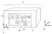
図2は、構成材6を詳細に示している。
FIG. 2 shows the
構成材6は、壁の構成要素として、すべて同一の構造であるので、その1つのみを詳細に示す。
Since all the
構成材6は、例えば、1トン以上の荷重に耐えるように十分に強固である。例えば、ヤング率が、10 GPa(ギガパスカル)若しくは20GPaよりも大きな材料、若しくはその混合物である。
The
構成材6は、他の構成材6と容易に結合しうるように作られている。例えば、各構成材6は、別の構成材6が配置されるような、少なくとも1つの平坦な支持面を有している。図示の実施態様においては、構成材6は、四角形の平行六面体である。
The
モジュール12は、構成材6を形成する材料の内部に埋め込まれている。モジュール12は、構成材6の各面と同一面をなし、各面から突出していない。
The
モジュール12は、方向センサ50を備え、座標系Roの3次元座標の軸Xo,Yo,Zoに対する構成材の傾きを測定する。
The
方向センサ50は、例えば、慣性プラットフォームである。
The
慣性プラットフォーム及びその操作は、非特許文献2及び3に記載されている。
Inertial platforms and their operation are described in
方向センサ50は、3軸加速度計52、3軸磁力計54及び3軸ジャイロメータ56を備えている。
The
加速度計52は、座標系Rにおける重力場の方向を測定可能である。座標系Rは、構成材6に設けられている。3本の軸X,Y,Zは同一平面上及び同一直線上にはなく、互いに直交している。例えば、軸X,Yは、構成材6の下面と平行であり、軸X,Zは、構成材6の側面と平行である。加速度計52は、座標系Rにおける加速度ベクトルarの座標を測定する。静的若しくは準静的な状態において、ベクトルarは、次式により、座標系Roで測定された重力場のベクトルaoと連結されている。
(1)ar = Pao
式中、Pは、座標系Roにおける構成材6の方向を与える行列を示す。
The
(1) a r = Pa o
In the equation, P represents a matrix that gives the direction of the
「静的若しくは準静的」なる用語は、構成材6の動きによる加速度の大きさが、重力場における強度に比べ、無視しうる状態を意味している。例えば、加速度の大きさが、重力場の強度の少なくとも1/3、1/10、若しくは1/30である場合、無視しうると見做される。
The term “static or quasi-static” means a state in which the magnitude of acceleration due to the movement of the
行列Pは、構成材6の方向を決定する5つの未知数を含んでいる。
The matrix P includes five unknowns that determine the direction of the
3軸加速度計は、アナログデバイス(ANALOG DEVICE社)により、商品名「ADXL327BCPZ」で市販されている加速度計である。 The triaxial accelerometer is an accelerometer marketed under the trade name “ADXL327BCPZ” by an analog device (ANALOG DEVICE).
磁力計54は、座標系Rにおける地球磁場の座標hrを測定する。座標系Rにおける座標hrは、次式により、座標系Roにおける地球磁場の座標hoに関係している。
(1)hr = Pho
式中、hrは、座標系Rで測定された地球磁場の座標、hoは、座標系Roで測定された地球磁場の座標、Pは、式(1)と同一の行列を示す。
The
(1) h r = Ph o
Wherein, h r is the coordinate system the coordinates of the geomagnetic field measured in the R, h o is the coordinate system R o measured geomagnetic field coordinates in, P is, shows the same matrix as the equation (1).
座標系Roにおいて、重力場及び地球磁場の座標ao及びhoは、予め定められた定数である。 In the coordinate system R o, gravitational field and coordinates a o and h o of the earth's magnetic field is a predetermined constant.
式(1)及び(2)は、5つの未知数と6つの等式を含んでいる。構成材6が、静的若しくは準静的であるという仮定の下に、座標系Roにおける、構成材6の方向性を決定する。
Equations (1) and (2) contain 5 unknowns and 6 equations. Under the assumption that the
5つの未知数のための6つの等式が、測定される方向性の強固さを増大させることが可能である。特に、構成材6から機械的に独立した、外部の磁性材により引き起こされる磁気的な乱れを克服する。
Six equations for five unknowns can increase the robustness of the measured directionality. In particular, it overcomes the magnetic turbulence caused by an external magnetic material that is mechanically independent from the
ジャイロメーター56は、3本の軸X,Y,Z回りの構成材6の角速度を測定する。構成材6が静的若しくは準静的でないとしても、ジャイロメーターにより、構成材6の方向を測定することが出来る。そのため、ジャイロメーターにより、一定でない速度での運動において、構成材6の方向を測定することが出来る。
The
センサ50は、プログラム可能に埋め込まれた計算機58に接続されている。計算機58は、モジュール12のメモリ60に記録された指令を実行する。メモリ60は、図3の方法を実行するのに必要な指令を持っている。
The
モジュール12は、エミッタ62と、モジュール12の各電子部品を駆動するバッテリ64と、モジュール12の各部品を保護する、剛体のシェル66を備えている。
The
エミッタ62は、計算機58に接続されている。エミッタ62は、リンク14により、情報を伝達する。
The
例えば、シェル66は、構成材6の材料よりも、ヤング率のより大きな材料で作られている。シェル66のヤング率は、50GPa若しくは70GPaよりも大きい。モジュール12の前述した電子部品は、シェル66内に収容され、保護するようになっている。
For example, the
構成材6の製造及びシステム2の操作を、図3の方法に基づき説明する。
The manufacture of the
最初に、工程80で、構成材6を製造する。
First, in
段階82において、各構成材6が製造され、モジュール12は、構成材6に組み込まれる。
In
例えばモジュール12が、構成材6を作るのに使用される原材料に組み込まれる。その後、モジュール12を含む原材料を成形して、構成材の形を得る。この場合、座標系Rに関するモジュール12の方向性は、段階82の完了時に未知である。
For example, the
製造の別の実施態様においては、構成材6を製造し、そのハウジングを中空にして、モジュール12を入れるようにする。その後、モジュール12は、ハウジングに固定される。例えば、モジュール12を、ハウジングの底部に置き、ハウジングを再び密封する。好ましくは、座標系Rにおけるモジュールの方向性が分かれるように、所定の方向性で、ハウジング内に、モジュール12を挿入するのがよい。
In another embodiment of manufacture, the
段階82の次に、座標系Rにおけるモジュールの方向性が知られていない場合、校正段階84を実施する。この段階84において、構成材6を所定の方向性に置き、センサ50により、構成材6の方向性を測定する。測定された方向性は、校正方向性と呼ばれる。その後、計算機58は、エミッタ62により発信された測定方向性を、校正方向性の関数として補正する。そこで、構成材が何であろうと、発信された測定値は、同一の座標系Roで測定された方向性に対応する。
Following
製造段階は、このようにして完了する。 The manufacturing phase is thus completed.
次に、作業現場への構成材の供給が開始される。構成材は、製品が組み立てられる作業現場に送られ、壁4を組み立てる工程90が始まる。
Next, supply of components to the work site is started. The component is sent to the work site where the product is assembled and the
段階92で、各構成材の間に詰められる結合剤8の厚味を考慮しながら、労働プランに基づき、表36を作る。
At
各構成材を配置する間に、使用者は、システム2の支援を受ける。
During the placement of each component, the user is assisted by the
システム2の操作について、壁4におけるi番目の構成材6を配置する場合について説明する。
The operation of the
段階94の間に、供給されたi番目の構成材は、使用者により、壁4の方に移動される。計算機58が、この動きを検知する。例えば、加速度計52の測定に基づき、計算機58が、構成材6の動きを検知する。これに応答して、待機モードを終了し、アクティブモードに入る。
During
アクティブモードの段階96において、センサ50は、座標系Roにおける、構成材6の方向性を測定し、測定された方向性をエミッタ62に送り、かつ装置10に送る。
In the
段階98において、エミッタ62により発信された電磁波に基づき、センサ20は、構成材6の位置を測定する。
In
段階100において、計算機38は、表36から、通し番号iに対応する、設定値Coi及びCpiを選択する。
In
段階102において、計算機38は、測定された方向性と方向性設定値Coiとの間の不一致を計算する。計算機38は、また、センサ20により測定された位置と、位置設定値Cpiとの間の不一致を計算する。
In
段階104において、計算機38は、計算された不一致が顕著なものであるかどうかを決定する。例えば、段階104において、計算機38は、所定の閾値と、計算された不一致を比較する。所定の閾値に交差すると、不一致は顕著である。
In
少なくとも1つの顕著な不一致が存在すると、計算機は段階106に進み、人・機械インターフェースに指令し、使用者に不一致を指摘する。 If there is at least one significant discrepancy, the computer proceeds to step 106 and commands the man-machine interface to indicate the discrepancy to the user.
これに応答して、段階108において、使用者は、指摘された不一致の関数として、構成材6の配置を調整し、不一致を減少させることを試みる。段階94に戻り、i番目の構成材の配置を調整する作業を続行する。
In response, at
段階104において、計算機38により、不一致が顕著でないことを確認すると、構成材が正確に配置されたことが示されている。この場合、段階110において、計算機38は、人・機械インターフエースを介して、構成材38が正確に配置されたことを指摘する。これに応答して、使用者は構成材6を固定する。
In
段階110と並置した段階114において、計算機38は、次の構成材が配置されることを確認する。この実施態様において、単にiを増やすことで、次の構成材が配置されることとなる。
In
段階112において、構成材6の計算機58は、所定の時間内での、動きの欠如を検知する。構成材6がこの所定の時間内に動かなかった場合には、アクティブモードが自動的に待機モードになる。待機モードにおいて、エミッタ62は、非作動になり、構成材6は、電磁波を発信しなくなる。更に、待機モードにおいて、磁力計54とジャイロメータ56は、非作動となり、バッテリー64に蓄えたエネルギーを節約する。
In
その後、段階94に戻り、(i + 1)番目の構成材を配置する。 Thereafter, returning to step 94, the (i + 1) -th component is arranged.
幾多の他の実施態様が可能である。例えば、構成材は、砕石、柱、パイプ、パイプラインパイプ、窓ガラス、ポリマープレート、コンクリートブロックなどでもよい。 A number of other embodiments are possible. For example, the constituent material may be crushed stone, pillar, pipe, pipeline pipe, window glass, polymer plate, concrete block, or the like.
構成材は、別の構成材と合致するような、孔や突起を備えていてもよい。 The component may have holes or protrusions that match another component.
モジュールを構成材に埋め込まなくてもよい。例えば、構成材の外面に、接着剤やネジにより固定してもよい。 The module need not be embedded in the component. For example, you may fix to the outer surface of a component material with an adhesive agent or a screw | thread.
測定するための、加速度計、磁力計及びジャイロメーターにおける座標系は、一致しなくてもよい。しかし、それらは互いに固定され、互いに対する座標系の位置は、知られていることが必要である。 The coordinate systems in the accelerometer, magnetometer, and gyrometer for measurement need not match. However, they are fixed to each other and the position of the coordinate system relative to each other needs to be known.
方向性センサの他の実施態様も可能である。例えば、方向性センサは、3つのコーダーフイールよりなっていてもよい。これらのコーダーフイールは、座標系Rの各軸と重力場に自動的に平行に配置された可動アームとの間の角度を決定する。 Other embodiments of directional sensors are possible. For example, the directional sensor may consist of three coder files. These coder feels determine the angle between each axis of the coordinate system R and a movable arm automatically placed parallel to the gravitational field.
構成材の位置を調整する時の動きが、静的若しくは準静的状態を維持するのに十分に緩慢である場合には、ジャイロメーター56を省いてもよい。ジャイロメーター56を不要にするために、新たな測定の前に、動きの終了を待ってもよい。
The
位置センサを、構成材に組み込んでもよい。この場合、発信装置10のセンサ20は省いてもよい。組み込まれたセンサにより測定された位置は、エミッタ62により、発信装置10に発信される。構成材に組み込まれた位置センサは、例えば、GPS(全地球測位システム)センサであるのがよい。
A position sensor may be incorporated into the component. In this case, the
別の実施態様においては、位置センサは省かれる。この場合、構成材を配置するための操作について、システムは使用者を補助するだけである。 In another embodiment, the position sensor is omitted. In this case, the system only assists the user in the operation for placing the component.
モジュール12は、温度センサ及び圧力センサのような他のセンサを備えることにより、構成材の状態について、追加の情報を提供してもよい。
モジュール12は、バッテリー以外の手段により駆動されてもよい。例えば、電磁波のような無線方式により、モジュール12にエネルギーを送ってもよい。モジュール12を、運動の機械的エネルギーを電気的エネルギーに変換するシステムにより作動してもよい。
The
別の実施態様においては、発信装置10は、各構成材に組み込まれ、同様な機能を発揮する。しかし、この場合、人・機械インターフェースは単純化される。例えば、一式の発光ダイオードを備えるスクリーンよりなっている。例えば、測定された方向性及び位置と、方向性設定値及び位置設定値との間の不一致が大きければ大きいほど、発光ダイオードは、より速く点滅する。人・機械インターフェースは、震動を感知するセンサの助けを借りてもよい。
In another embodiment, the transmitting
別の実施態様においては、モジュールは、加速度計、磁力計及びジャイロメーターの測定値を発信装置10に発信する。座標系Roに方向性は、発信された測定値に基づき、発信装置により決定される。
In another embodiment, the module transmits accelerometer, magnetometer and gyrometer measurements to
モジュールは、受信機を備えていてもよい。受信機は、方向性設定値Coi及び位置設定値Cpiをモジュールに送り、それらを記録する。これらの設定値Coi及びCpiと測定値との間の不一致は、モジュール12内部の計算機58で計算される。
The module may comprise a receiver. The receiver sends the directionality setting value Coi and the position setting value Cpi to the module and records them. The discrepancies between these set values Coi and Cpi and the measured values are calculated by the
発信装置10は、センサ20と独立した受信機を備えていてもよい。
The transmitting
変形例においては、識別子から次の識別子(i+1)への移動は、構成材の動きの欠如を検知するのとは、異なる方法で行われる。例えば、識別子の増大は、使用者が手でボタンを押すことにより開始される。 In a variant, the movement from one identifier to the next identifier (i + 1) is performed in a different way than detecting the lack of movement of the component. For example, the increase in identifier is initiated by the user pressing a button with his hand.
表36の識別子は、通し番号でなくてもよい。例えば、すべての構成材から、個別に選択することが出来る識別子を、各モジュール12のメモリ60に記憶しておいてもよい。識別子iは、次に、方向性の測定と同時に、発信される。発信装置は、受信した識別子iにより、表36から設定値Coi及びCpiを検索するのに使用される。発見された設定値は、方向性と位置に関して、設定値と測定値を比較するのに使用される。
The identifier in Table 36 may not be a serial number. For example, identifiers that can be individually selected from all the components may be stored in the memory 60 of each
別の実施態様においては、各構成材6のメモリ60に記録された識別子は、すべての構成材6で同一である。例えば、同じ寸法のすべてのレンガは同一の識別子を持っている。即ち、互いに交換しえる構成材は、同じ識別子を持っている。
In another embodiment, the identifier recorded in the memory 60 of each
所定の構成材の方向性設定値及び位置設定値は、既に同様な仕事でされた別の構成材で測定された方向性設定値及び位置設定値の関数として、予め決定される。 The directionality setting value and the position setting value of a predetermined component are determined in advance as a function of the directionality setting value and the position setting value measured with another component that has already been performed in the same manner.
構成材の配置を調製する段階108は、構成材を把持し、方向性と位置を調整する手段を使用する、人や操縦ロボットにより実行されてもよい。ロボットは、モータにより駆動される。ロボットの場合、発信装置が、ロボットに一定の不一致を発信し、それにより、ロボットが、受信した不一致の関数として、構成材の配置を調整する。後者の実施態様においては、発信装置はロボットに組み込まれている。
The
上記に述べたものは、土木工学の分野の種々のタイプのものに使用出来る。例えば、パイプライン、橋などを結合する、壁や他の構成材に使用出来る。 What has been described above can be used for various types in the field of civil engineering. For example, it can be used for walls and other components that connect pipelines, bridges, etc.
2 システム
4 壁
6 構成材
10 発信装置
12 ジュール
14 無線送信
22 メモリ
36 表
38 計算機
40 インターフェース
50 方向センサ
52 3軸加速度計
54 3軸磁力計
56 3軸ジャイロメータ
58 計算機
60 メモリ
62 エミッタ
66 シェル
2 System 4
56 3-
Claims (12)
各構成材が、構成材に対して、自由度なしに固定された、少なくとも1つのセンサを備え、同一平面上にない、3本の軸に対する構成材の傾きを測定可能であり、
各構成材の方向性を調整する段階(108)が、方向性設定値と、構成材に固定された方向性センサによる方向性測定値との間の、不一致の関数として実行されることを特徴とする方法。 In a method for supporting the placement of components in civil engineering, including the step (108) of adjusting the directionality of the components as a function of the discrepancy between the directionality measurements of the components and the directionality settings.
Each component has at least one sensor fixed to the component without any degree of freedom, and can measure the inclination of the component relative to three axes that are not on the same plane,
The step of adjusting the directionality of each component (108) is performed as a function of the discrepancy between the directionality set value and the directionality measurement by a directionality sensor fixed to the component. And how to.
いくつかの方向性設定値を含む表で、認識された構成材の関数として、方向性設定値を選定する段階(100)と、
認識された構成材の方向性測定値と、選択された設定値との間の不一致を指摘する段階とを含む請求項1に記載の方法。 Recognizing the placed component (114);
Selecting a directionality setting value (100) as a function of a recognized component in a table containing a number of directionality setting values; and
The method of claim 1 including indicating a discrepancy between a recognized component directionality measurement and a selected setpoint.
同一平面上にない、3本の軸に対し、構成材の傾きを測定可能な、少なくとも1本の方向性センサ(50)とを備える、土木工事の構成材の配置を支援するシステムにおいて、
各構成材(6)は、この構成材に対し、自由度なしに、固定された少なくとも1つの方向性センサ(50)を備え、同一平面上にない、3本の軸に対し、構成材の傾きを測定することが可能で、前記システムが、構成材のいずれか1つの方向性センサによる方向性測定値と、構成材の方向性設定値との間の、不一致を指摘することが可能な電子的発信装置(10)を備えることを特徴とするシステム。 To construct the building, the components (6) arranged side by side,
In a system for supporting the arrangement of structural members for civil engineering, comprising at least one directional sensor (50) capable of measuring the inclination of the structural members with respect to three axes that are not on the same plane,
Each component (6) is provided with at least one directional sensor (50) fixed without any degree of freedom relative to this component, and the components of three components are not on the same plane. It is possible to measure the inclination, and the system can point out a discrepancy between the directionality measurement value by any one directionality sensor of the component and the directionality setting value of the component A system comprising an electronic transmitter (10).
人・機械インターフェースと、
構成材の固定された方向性センサによる方向性測定値と、構成材の方向性設定値との間の不一致を直接人間に理解可能に指摘するように、人・機械インターフェースを制御すべく、プログラミングされた少なくとも1つの電子計算機(38)とを備える、請求項4に記載のシステム。 The transmitting device (10) is mechanically independent from the components, and
Human-machine interface,
Programming to control the human / machine interface to point out the discrepancies between the directionality measured by the fixed directionality sensor of the component and the directionality setting of the component in a way that can be directly understood by humans The system according to claim 4, comprising at least one electronic computer (38).
Applications Claiming Priority (2)
| Application Number | Priority Date | Filing Date | Title |
|---|---|---|---|
| FR1151575 | 2011-02-25 | ||
| FR1151575A FR2972012B1 (en) | 2011-02-25 | 2011-02-25 | METHOD FOR ASSISTING THE PLACEMENT OF CONSTRUCTION ELEMENTS OF A CIVIL ENGINEERING WORK |
Publications (1)
| Publication Number | Publication Date |
|---|---|
| JP2012177295A true JP2012177295A (en) | 2012-09-13 |
Family
ID=45592277
Family Applications (1)
| Application Number | Title | Priority Date | Filing Date |
|---|---|---|---|
| JP2012038317A Pending JP2012177295A (en) | 2011-02-25 | 2012-02-24 | Method and system for supporting arrangement of constituent members in civil engineering |
Country Status (4)
| Country | Link |
|---|---|
| US (1) | US9163417B2 (en) |
| EP (1) | EP2492417B1 (en) |
| JP (1) | JP2012177295A (en) |
| FR (1) | FR2972012B1 (en) |
Cited By (1)
| Publication number | Priority date | Publication date | Assignee | Title |
|---|---|---|---|---|
| CN112796227A (en) * | 2021-04-09 | 2021-05-14 | 湖南久钰电子有限公司 | Bridge deck construction monitoring method and system |
Families Citing this family (10)
| Publication number | Priority date | Publication date | Assignee | Title |
|---|---|---|---|---|
| FR2999699B1 (en) * | 2012-12-19 | 2015-12-11 | Commissariat Energie Atomique | METHOD FOR DETERMINING THE INCLINATION OF AN OBJECT |
| CN103362244B (en) * | 2013-06-25 | 2015-08-26 | 山东华宇职业技术学院 | The walling unit of the prefabricated nail of indoor suspension thing |
| CN103452327B (en) * | 2013-08-30 | 2016-05-11 | 山西四建集团有限公司 | Constructional column bar planting positioning construction method |
| CN103894312B (en) * | 2014-03-28 | 2016-04-13 | 郑州格兰高环境工程有限公司 | Intelligent mobile glue make-up system |
| FR3025965B1 (en) | 2014-09-15 | 2016-09-30 | Oberthur Technologies | METHOD FOR ADMINISTERING LIFE CYCLES OF COMMUNICATION PROFILES |
| CN106150112B (en) * | 2015-04-17 | 2018-08-24 | 张成芳 | A kind of wall-building machine mortar induction controller |
| CN107740591B (en) * | 2017-10-19 | 2020-07-07 | 厦门华蔚物联网科技有限公司 | T-shaped wall building method of brick building robot |
| CN107605167B (en) * | 2017-10-19 | 2020-07-10 | 厦门华蔚物联网科技有限公司 | Right-angle wall building method of brick-building robot |
| CN107654077B (en) * | 2017-10-19 | 2020-04-03 | 厦门华蔚物联网科技有限公司 | Masonry algorithm of brick-laying robot linear wall body considering mortar plasticity |
| CN115807412A (en) * | 2022-11-29 | 2023-03-17 | 中国电建集团成都勘测设计研究院有限公司 | Intelligent installation method for large-diameter pressure steel pipe in hole |
Family Cites Families (10)
| Publication number | Priority date | Publication date | Assignee | Title |
|---|---|---|---|---|
| SE8400484D0 (en) * | 1984-01-31 | 1984-01-31 | Slim Borgudd | DEVICE FOR SURGERY OF DYNAMIC AND STATIC LOAD PACKAGING BY A TOWING DEVICE FOR EX DRIVER |
| CH673498A5 (en) * | 1986-08-27 | 1990-03-15 | Thomas Albert Pfister | Automatic brick laying system using programme-controlled robot - uses gripper to transfer bricks with simultaneous feed of bedding mortar |
| DE4409150A1 (en) | 1994-03-17 | 1995-09-21 | Bosch Gmbh Robert | Electronically controlled hydraulic drive for double level parking garage |
| DE19520795C3 (en) | 1995-06-07 | 2002-09-05 | Doka Ind Ges M B H Amstetten | Switching device for lifting elements |
| FR2842593B1 (en) | 2002-07-19 | 2004-10-22 | Spacemetric Sa | ELECTRONIC TILT INDICATOR |
| WO2010120402A1 (en) * | 2009-04-13 | 2010-10-21 | Deka Products Limited Partnership | System and apparatus for orientation control |
| US8024980B2 (en) * | 2008-01-24 | 2011-09-27 | Microstrain, Inc. | Independently calibrated wireless structural load sensor |
| DE102008016004B4 (en) | 2008-03-27 | 2024-07-25 | Fraunhofer-Gesellschaft zur Förderung der angewandten Forschung e.V. | Microelectromechanical inertial sensor with atmospheric damping |
| US8138938B2 (en) * | 2008-10-28 | 2012-03-20 | The Boeing Company | Hand-held positioning interface for spatial query |
| FR2946134B1 (en) | 2009-05-26 | 2011-10-21 | Executive Assets Man Group | ASSISTING THE RIGHT POSITIONING OF A TABLE OR SIMILAR OBJECT. |
-
2011
- 2011-02-25 FR FR1151575A patent/FR2972012B1/en not_active Expired - Fee Related
-
2012
- 2012-02-15 US US13/397,274 patent/US9163417B2/en not_active Expired - Fee Related
- 2012-02-21 EP EP12156377.9A patent/EP2492417B1/en not_active Not-in-force
- 2012-02-24 JP JP2012038317A patent/JP2012177295A/en active Pending
Cited By (2)
| Publication number | Priority date | Publication date | Assignee | Title |
|---|---|---|---|---|
| CN112796227A (en) * | 2021-04-09 | 2021-05-14 | 湖南久钰电子有限公司 | Bridge deck construction monitoring method and system |
| CN112796227B (en) * | 2021-04-09 | 2021-06-29 | 湖南久钰电子有限公司 | Bridge deck construction monitoring method and system |
Also Published As
| Publication number | Publication date |
|---|---|
| FR2972012B1 (en) | 2013-03-15 |
| EP2492417B1 (en) | 2016-12-14 |
| FR2972012A1 (en) | 2012-08-31 |
| EP2492417A1 (en) | 2012-08-29 |
| US9163417B2 (en) | 2015-10-20 |
| US20120221292A1 (en) | 2012-08-30 |
Similar Documents
| Publication | Publication Date | Title |
|---|---|---|
| JP2012177295A (en) | Method and system for supporting arrangement of constituent members in civil engineering | |
| US9377303B2 (en) | Surveying appliance and method having a targeting functionality which is based on the orientation of a remote control unit and is scalable | |
| US8166727B2 (en) | Automated brick laying system for constructing a building from a plurality of bricks | |
| US8595946B2 (en) | Two dimension layout and point transfer system | |
| US7447565B2 (en) | Electronic alignment system | |
| JP4646697B2 (en) | Portable device | |
| CN104613946A (en) | Three-dimensional measuring method and surveying system | |
| KR102365708B1 (en) | Calibration method for gyro sensor using tilt sensor | |
| CN105353776A (en) | Control system, method and device of arm support and engineering machinery | |
| CN104389584A (en) | High-speed continuous gyroscopic inclinometer system | |
| JP2019069850A (en) | Method of moving cargo by using crane | |
| Keating et al. | A compound arm approach to digital construction | |
| CN205593534U (en) | Micro electronmechanical gyroscope and electronic system | |
| JP2012154912A (en) | Measurement system, computation apparatus and structure | |
| CN104864842B (en) | Moment feedback gyroscopic total station based on static mode | |
| JP2018179533A (en) | Inclination measurement device, measurement method of accuracy of steel column election using same, calibration method of inclination measurement device, and inclination measurement processing program | |
| CN107526082A (en) | mobile observation phased array weather radar | |
| CN209310806U (en) | A kind of Laser Line Marker of adjustable spacing | |
| CN102410845A (en) | Method and device for correcting error, detecting angular speed and controlling mouse, and space mouse | |
| CN102331512B (en) | Two-dimensional/three-dimensional angular speed detecting device and method and attitude sensing equipment | |
| CN102419174B (en) | Two-dimensional/three-dimensional angular velocity detection devices as well as angular velocity detection methods and attitude sensing devices of detection devices | |
| EP3258678A1 (en) | Application and method to prevent undue call in a mobile device | |
| KR20070072319A (en) | Method and apparatus for estimation of angular velocity using 2 linear acceleration sensors | |
| KR101519431B1 (en) | Azimuth providing apparatus | |
| KR101419874B1 (en) | Operator standpoint-based remote operation system and method for mobile object |