JP2012174871A - Solar cell module - Google Patents
Solar cell module Download PDFInfo
- Publication number
- JP2012174871A JP2012174871A JP2011035009A JP2011035009A JP2012174871A JP 2012174871 A JP2012174871 A JP 2012174871A JP 2011035009 A JP2011035009 A JP 2011035009A JP 2011035009 A JP2011035009 A JP 2011035009A JP 2012174871 A JP2012174871 A JP 2012174871A
- Authority
- JP
- Japan
- Prior art keywords
- solar cell
- cell
- solar
- plan
- cell module
- Prior art date
- Legal status (The legal status is an assumption and is not a legal conclusion. Google has not performed a legal analysis and makes no representation as to the accuracy of the status listed.)
- Granted
Links
Images


Classifications
-
- Y—GENERAL TAGGING OF NEW TECHNOLOGICAL DEVELOPMENTS; GENERAL TAGGING OF CROSS-SECTIONAL TECHNOLOGIES SPANNING OVER SEVERAL SECTIONS OF THE IPC; TECHNICAL SUBJECTS COVERED BY FORMER USPC CROSS-REFERENCE ART COLLECTIONS [XRACs] AND DIGESTS
- Y02—TECHNOLOGIES OR APPLICATIONS FOR MITIGATION OR ADAPTATION AGAINST CLIMATE CHANGE
- Y02E—REDUCTION OF GREENHOUSE GAS [GHG] EMISSIONS, RELATED TO ENERGY GENERATION, TRANSMISSION OR DISTRIBUTION
- Y02E10/00—Energy generation through renewable energy sources
- Y02E10/50—Photovoltaic [PV] energy
Landscapes
- Photovoltaic Devices (AREA)
Abstract
Description
本発明は、複数の太陽電池セルが並べて配置された太陽電池モジュールに関する。 The present invention relates to a solar cell module in which a plurality of solar cells are arranged side by side.
従来、複数の太陽電池セルが平面内に並べて配置された太陽電池モジュールが用いられている。太陽電池モジュールは、全体としての平面形状が、略方形形状を呈するものや、略三角形形状を呈するものや略台形形状を呈するものなどが知られている。 Conventionally, a solar cell module in which a plurality of solar cells are arranged in a plane is used. As for the solar cell module, those having a planar shape as a whole, a substantially rectangular shape, a substantially triangular shape, a substantially trapezoidal shape, and the like are known.
ここで、略三角形形状を呈する太陽電池モジュールや、略台形形状を呈する太陽電池モジュールのように、頂点の一部が鋭角となっている場合には、方形形状かつ同サイズの太陽電池セルを並べた場合に、鋭角となっている頂点から延びる1辺に沿って太陽電池セルの無い空白部分が生じてしまう。そのため、空白部分によって発電効率にロスが生じるという問題や、美観を損ねてしまうという問題があった。 Here, when a part of the apex has an acute angle, such as a solar cell module having a substantially triangular shape or a solar cell module having a substantially trapezoidal shape, solar cells having a rectangular shape and the same size are arranged. In this case, a blank portion without a solar battery cell is generated along one side extending from the apex having an acute angle. For this reason, there is a problem that the power generation efficiency is lost due to the blank portion and a problem that the aesthetics are impaired.
そこで、空白部分にダミーセルを配置する技術や、三角形形状を呈する太陽電池セルを用意して空白部分に配置する技術が、例えば特許文献1に開示されている。
Therefore, for example,
しかしながら、ダミーセルを配置するだけでは発電効率の問題を解決することができない。また、三角形形状を呈する太陽電池セルを配置した場合には、方形形状を呈する太陽電池セルと表面積が異なるため、発電する電流値が異なってしまう。発電する電流値の異なる太陽電池セルを直列接続した場合、出力される電流の値は面積の小さいセルの発電電流と同じ値になってしまう。そのため、効率改善を目的として加えた三角形セルが原因で方形形状を呈する太陽電池セルの能力を下げてしまうという問題があった。 However, the problem of power generation efficiency cannot be solved only by arranging dummy cells. In addition, when solar cells having a triangular shape are arranged, the surface area is different from that of a solar cell having a square shape, and thus the current value to be generated is different. When solar cells having different current values for power generation are connected in series, the value of the output current becomes the same value as the power generation current of a cell having a small area. Therefore, there has been a problem that the ability of the solar battery cell having a square shape is lowered due to the triangular cell added for the purpose of improving efficiency.
本発明は、上記に鑑みてなされたものであって、平面視において頂点の一部が鋭角となっている太陽電池モジュールにおいて、発電効率の向上を図ることのできる太陽電池モジュールを得ることを目的とする。 The present invention has been made in view of the above, and an object of the present invention is to obtain a solar cell module capable of improving power generation efficiency in a solar cell module in which a part of the apex has an acute angle in plan view. And
上述した課題を解決し、目的を達成するために、本発明は、平面形状における少なくとも1の頂点においてその角度が鋭角であり、平面内に第1太陽電池セルと第2太陽電池セルが並べて配置された太陽電池モジュールであって、第1太陽電池セルは、平面視において略直角三角形形状を呈し、角度が鋭角となる頂点から延びる1辺に斜辺が沿うように並べて第1太陽電池セルが配置され、第1太陽電池セルおよび第2太陽電池セルを少なくとも1つ含んだセル群が構成され、セル群に含まれる第1太陽電池セルおよび第2太陽電池セルの表面積は、セル群同士で略等しくなっており、セル群同士を直列に接続する接続部をさらに備えることを特徴とする。 In order to solve the above-described problems and achieve the object, the present invention has an acute angle at at least one vertex in a planar shape, and the first solar cell and the second solar cell are arranged side by side in the plane. In the solar cell module, the first solar cell has a substantially right triangle shape in plan view, and the first solar cell is arranged so that the hypotenuse extends along one side extending from the apex having an acute angle. A cell group including at least one of the first solar cell and the second solar cell is configured, and the surface areas of the first solar cell and the second solar cell included in the cell group are substantially the same between the cell groups. It is equal, It is characterized by further providing the connection part which connects cell groups in series.
本発明によれば、セル群に含まれる第1太陽電池セルおよび第2太陽電池セルの表面積を、セル群同士で略等しくすることで、セル郡同士の発電電流を等しくすることができ、平面視において頂点の一部が鋭角となっている太陽電池モジュールにおいて、発電効率の向上を図ることができるという効果を奏する。 According to the present invention, by making the surface areas of the first solar cell and the second solar cell included in the cell group substantially equal between the cell groups, the generated currents between the cell groups can be equalized, In the solar cell module in which a part of the apex has an acute angle in view, the power generation efficiency can be improved.
以下に、本発明の実施の形態にかかる太陽電池モジュールを図面に基づいて詳細に説明する。なお、この実施の形態によりこの発明が限定されるものではない。 Below, the solar cell module concerning embodiment of this invention is demonstrated in detail based on drawing. Note that the present invention is not limited to the embodiments.
実施の形態1.
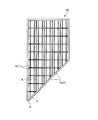
図1−1は、本発明の実施の形態1にかかる太陽電池モジュールの概略構成を示す平面図である。図1−2は、太陽電池セルの接続状態を説明するための太陽電池モジュールの平面図である。
FIG. 1-1 is a plan view illustrating a schematic configuration of the solar cell module according to the first embodiment of the present invention. FIG. 1-2 is a plan view of a solar cell module for explaining a connection state of solar cells.
図1−1,1−2の太陽電池モジュール10は、平面視において略直角三角形形状を呈しており、その平面内に太陽電池セル1が並べて配置されている。太陽電池セル1は、発電効率の向上のために、太陽電池モジュール10の平面内にほとんど隙間無く配置されている。太陽電池セル1は、第1太陽電池セル1aと、第2太陽電池セル1bとを有して構成される。
The
図2は、第2太陽電池セル1bの平面図である。図3は、第1太陽電池セル1aの平面図である。第2太陽電池セル1bは、図2に示すように、平面視において略正方形形状を呈している。太陽電池モジュールに用いられるセルとしては、一般的には、第2太陽電池セル11bのような略正方形形状を呈するセルが用いられる場合が多い。
FIG. 2 is a plan view of the second
第1太陽電池セル1aは、図3に示すように、平面視において略直角二等辺三角形形状を呈している。第1太陽電池セル1aは、図2に示す切断線2に沿って第2太陽電池セル1bを2分割した形状となっている。すなわち、第1太陽電池セル1aの表面積は、第2太陽電池セル1bの表面積の1/2となっている。
As shown in FIG. 3, the first
図1−1,1−2に戻って、太陽電池モジュール10は、平面形状において頂点AおよびBでその角度が鋭角、より具体的には略45度となるように構成されている。図4は、比較例としての太陽電池モジュールの平面図であって、第2太陽電池セルのみを並べて配置した状態を示す図である。比較例としての太陽電池モジュール30は、略正方形形状を呈する第2太陽電池セル1bのみを並べているので、頂点A,Bから延びる辺3に沿って、太陽電池セル1が配置されない空白部分が生じてしまう。一方、本実施の形態では、第2太陽電池セル1bを半分に切断した形状の第1太陽電池セル1aで、図4に示す空白部分を埋めている。この際、第1太陽電池セル1aの斜辺が、太陽電池モジュール10の辺に沿うように配置される。
Returning to FIGS. 1-1 and 1-2, the
そして、太陽電池モジュール10の平面内に並べられた太陽電池セル1同士は、図1−2に示すように、接続部4で電気的に接続される。ここで、1つの第2太陽電池セル1bを第2セル群6とし、2つの第1太陽電池セル1aを組み合わせて第1セル群5とする。このようにセル群5,6を構成することで、セル群5,6が有する太陽電池セル1の表面積同士が略等しくなる。
And the
そして、第1セル群5と第2セル群6とを、接続部4で電気的に直列に接続する。ここで、第1セル群5は、2つの第1太陽電池セル1aが、1つの第2太陽電池セル1bに並列に接続されることで、第1セル群5と第2セル群6とが直列に接続されることとなる。なお、太陽電池セル1同士の実際の接続は、太陽電池セル1の表面電極と、隣接する太陽電池セルの裏面電極をタブ線で接続し、それを繰り返すことで行われている。
Then, the
以上説明したように、比較例としての太陽電池モジュール30で生じた空白部分を、本実施の形態では第1太陽電池セル1aで埋めているので、実施の形態1にかかる太陽電池モジュール10のほうが、太陽電池セル1の表面積が大きくなり、発電効率の向上を図ることができる。
As described above, since the blank portion generated in the
また、直列接続される第1セル群5と第2セル群6とで太陽電池セル1の表面積を略等しくしているので、発電電流も同等とすることができる。ここで、電流値の異なる太陽電池セル(セル群)同士を直列接続した場合には、発電電流の小さいセル側の電流値がモジュールとしての出力電流の値となってしまう。
Moreover, since the surface area of the
一方、本実施の形態では、第1セル群5と第2セル群6とで太陽電池セル1の表面積を略等しくしているので、第1セル群5と第2セル群6とを直列接続した構成の太陽電池モジュール10において、より多くの発電電流を取り出すことができる。したがって、太陽電池モジュール10における発電効率の向上を図ることができる。
On the other hand, in the present embodiment, the
なお、本実施の形態では、鋭角となる頂点での角度が45度の場合を例に挙げて説明したがこれに限られない。鋭角となる頂点での角度が45度と異なる場合には、第2太陽電池セル11bとして略長方形形状を呈する太陽電池セルを用い、その第2太陽電池セル11bを2分割して直角三角形としたものを第1太陽電池セル11aとして用いることとなる。
In the present embodiment, the case where the angle at the apex that is an acute angle is 45 degrees has been described as an example, but the present invention is not limited thereto. When the angle at the apex that is an acute angle is different from 45 degrees, a solar cell having a substantially rectangular shape is used as the second
図5は、実施の形態1の変形例1にかかる太陽電池モジュール10の平面図である。太陽電池モジュール10が平面視において略三角形形状を呈しているのは、上記と同様である。本変形例1では、鋭角となる頂点A,Bからそれぞれ延びる2辺に対して、斜辺が沿うように第1太陽電池セル1aを並べて配置している。
FIG. 5 is a plan view of the
このように配置した場合にも、1つの第2太陽電池セル1bを第2セル群6とし、2つの第1太陽電池セル1aを組み合わせて第1セル群5とすることで、セル群5,6同士の太陽電池セル1の表面積を略等しくすることができる。そして、セル群5,6同士を直列で接続することで、太陽電池モジュール10における発電効率の向上を図ることができる。
Even when arranged in this way, one second
図6は、実施の形態1の変形例2にかかる太陽電池モジュール10の平面図である。本変形例2では、太陽電池モジュール10が略台形形状を呈する。そして、頂点Cでその角度が鋭角(略45度)となっている。また、頂点Cから延びる1つの辺に沿って斜辺が並ぶように第1太陽電池セル1aが配置される。
FIG. 6 is a plan view of the
このように配置した場合にも、1つの第2太陽電池セル1bを第2セル群6とし、2つの第1太陽電池セル1aを組み合わせて第1セル群5とすることで、セル群5,6同士の太陽電池セル1の表面積を略等しくすることができる。そして、セル群5,6同士を直列で接続することで、太陽電池モジュール10における発電効率の向上を図ることができる。
Even when arranged in this way, one second
図7は、実施の形態1の変形例3にかかる太陽電池モジュール10の平面図である。本変形例3では、太陽電池モジュール10が略平行四辺形形状を呈する。そして、頂点D,Eでその角度が鋭角(略45度)となっている。また、頂点D,Eからそれぞれ延びる1つの辺に沿って斜辺が並ぶように第1太陽電池セル1aが配置される。
FIG. 7 is a plan view of the
このように配置した場合にも、1つの第2太陽電池セル1bを第2セル群6とし、2つの第1太陽電池セル1aを組み合わせて第1セル群5とすることで、セル群5,6同士の太陽電池セル1の表面積を略等しくすることができる。そして、セル群5,6同士を直列で接続することで、太陽電池モジュール10における発電効率の向上を図ることができる。
Even when arranged in this way, one second
実施の形態2.
図8は、本発明の実施の形態2にかかる太陽電池モジュールの平面図である。なお、上記実施の形態と同様の構成については、同様の符号を付して詳細な説明を省略する。本実施の形態2では、太陽電池セル11が第1太陽電池セル11aと第2太陽電池セル11bとを有して構成される点で上記実施の形態1と同様である。ただし、第2太陽電池セル11bは、略長方形形状を呈しており、これは図2に示す第2太陽電池セル1aを切断線7で2分割したものと同じ形状となっている。したがって、1つの第1太陽電池セル11aの表面積と、1つの第2太陽電池セル11bの表面積とが、略等しくなっている。
FIG. 8 is a plan view of the solar cell module according to
そこで、1つの第2太陽電池セル11bを第2セル群16とし、1つの第1太陽電池セル11aを第1セル群15とすることで、セル群5,6が有する太陽電池セル11の表面積同士が略等しくなる。そして、このセル群15,16同士を電気的に直列に接続することで、発電電流を同等にして、発電効率の向上を図ることができる。
Therefore, the surface area of the
また、太陽電池セル11を1枚ずつ直列に接続するので、実施の形態1と比べて、各セルを接続する配線が簡単な構成で実現できる。また、一般的な正方形形状の太陽電池セルを半分にカットすることで、太陽電池セルの電流値も略半分になるため、電流がタブ線等を流れる際に発生する抵抗損失を減らすことができ、太陽電池モジュール40の出力と効率の向上を図ることができる。
Moreover, since the
なお、セル群15,16が有する太陽電池セル11の数は1つずつに限られず、セル群15,16それぞれが有する太陽電池セル11の数を同じにすれば、表面積も等しくすることができる。したがって、セル群15,16それぞれが有する太陽電池セル11の数が同じであれば、複数個の太陽電池セル11を有するようにセル群15,16を構成しても構わない。
The number of
実施の形態3.
図9は、本発明の実施の形態3にかかる太陽電池モジュールに並べられた太陽電池セルの一部を示す部分拡大平面図である。本実施の形態3では、図9に示すように、第1太陽電池セル21aも第2太陽電池セル21bも同じ略三角形形状のものを用いる。第1太陽電池セル21aと第2太陽電池セル21bとは、同じ形状であるので表面積も等しい。
Embodiment 3 FIG.
FIG. 9 is a partially enlarged plan view showing a part of solar cells arranged in the solar cell module according to Embodiment 3 of the present invention. In the third embodiment, as shown in FIG. 9, the first
したがって、1つの第2太陽電池セル21bを第2セル群26とし、1つの第1太陽電池セル21aを第1セル群25とすることで、セル群25,26が有する太陽電池セルの表面積同士が略等しくなる。そして、このセル群25,26同士を電気的に直列に接続することで、発電電流を同等にして、発電効率の向上を図ることができる。また、太陽電池セル21を1枚ずつ直列に接続するので、実施の形態1と比べて、各セルを接続する配線が簡単な構成で実現できる。
Therefore, the surface area of the solar cell which the
また、太陽電池セル21を1枚ずつ直列に接続するので、実施の形態1と比べて、各セルを接続する配線が簡単な構成で実現できる。また、一般的な正方形形状の太陽電池セルを半分にカットすることで、太陽電池セルの電流値も略半分になるため、電流がタブ線等を流れる際に発生する抵抗損失を減らすことができ、太陽電池モジュール50の出力と効率の向上を図ることができる。
Further, since the
また、略三角形形状を呈する1種類の太陽電池セル21を用意すれば、第1太陽電池セル21aとしても、第2太陽電池セル21bとしても利用できるので、部品点数の削減を図り、コストの抑制を図ることができる。
In addition, if one type of
また、上記実施の形態2では、太陽電池セルを準備するために、正方形形状の太陽電池セルを切断線2に沿って切断する場合と、切断線7に沿って切断する場合とがある(図2も参照)。一方、本実施の形態2では、切断線2に沿って太陽電池セルを切断することで太陽電池セルを準備することができるので、段取り替えの手間を省略したり、作業スペースの省スペース化を図ったりすることができる。
Moreover, in the said
実施の形態4.
形状が同一でも特性の異なる(発電電流が異なる)太陽電池セル同士の場合、表面積を揃えるだけでは太陽電池モジュール全体からの出力電流を最大限に取り出すことが難しい場合がある。その場合は、直列接続するセル群同士で発電電流の値が同等になるように、各セル群内での太陽電池セルの並列数を定めればよい(図示は省略)。
In the case of solar cells having the same shape but different characteristics (different generation currents), it may be difficult to extract the output current from the entire solar cell module to the maximum by just aligning the surface area. In that case, what is necessary is just to determine the parallel number of the photovoltaic cell in each cell group so that the value of an electric power generation current may become equal between the cell groups connected in series (illustration is abbreviate | omitted).
以上のように、本発明にかかる太陽電池モジュールは、複数の太陽電池セルが並べて配置された太陽電池モジュールに有用であり、特に、その平面形状において鋭角となる頂点を有する太陽電池モジュールに適している。 As described above, the solar cell module according to the present invention is useful for a solar cell module in which a plurality of solar cells are arranged side by side, and is particularly suitable for a solar cell module having an apex that has an acute angle in its planar shape. Yes.
1 太陽電池セル
1a 第1太陽電池セル
1b 第2太陽電池セル
2 切断線
3 辺
4 接続部
5 第1セル群
6 第2セル群
7 切断線
10,30,40,50 太陽電池モジュール
11 太陽電池セル
11a 第1太陽電池セル
11b 第2太陽電池セル
15 第1セル群
16 第2セル群
21 太陽電池セル
21a 第1太陽電池セル
21b 第2太陽電池セル
25 第1セル群
26 第2セル群
A,B,C,D,E 頂点
DESCRIPTION OF
Claims (8)
前記第1太陽電池セルは、平面視において略直角三角形形状を呈し、
角度が鋭角となる前記頂点から延びる1辺に斜辺が沿うように並べて前記第1太陽電池セルが配置され、
前記第1太陽電池セルおよび前記第2太陽電池セルを少なくとも1つ含んだセル群が構成され、
前記セル群に含まれる前記第1太陽電池セルおよび前記第2太陽電池セルの表面積は、前記セル群同士で略等しくなっており、
前記セル群同士を直列に接続する接続部をさらに備えることを特徴とする太陽電池モジュール。 The solar cell module in which the angle is an acute angle at at least one vertex in the planar shape, and the first solar cell and the second solar cell are arranged side by side in the plane,
The first solar cell has a substantially right triangle shape in plan view,
The first solar cells are arranged side by side so that the hypotenuse extends along one side extending from the apex having an acute angle,
A cell group including at least one of the first solar cell and the second solar cell is configured,
The surface areas of the first solar cell and the second solar cell included in the cell group are substantially equal between the cell groups,
The solar cell module further comprising a connection part for connecting the cell groups in series.
前記第1太陽電池セルは、平面視において略直角二等辺三角形形状を呈することを特徴とする請求項1に記載の太陽電池モジュール。 The acute angle is approximately 45 degrees;
2. The solar cell module according to claim 1, wherein the first solar cell has a substantially right-angled isosceles triangle shape in a plan view.
前記第1太陽電池セルは、前記第2太陽電池と略同じ大きさの正方形を2分割した形状を呈し、
前記セル群は、2つの第1太陽電池セルで構成された第1セル群と、1つの第2太陽電池セルで構成された第2セル群と、を有して構成され、
前記接続部は、前記2つの第1太陽電池セルを前記1つの第2太陽電池に並列接続させることで、前記第1セル群と前記第2セル群とを直列に接続することを特徴とする請求項2に記載の太陽電池モジュール。 The second solar cell has a substantially square shape in plan view,
The first solar cell has a shape obtained by dividing a square having substantially the same size as the second solar cell into two parts,
The cell group includes a first cell group composed of two first solar cells and a second cell group composed of one second solar cell,
The connection unit connects the first cell group and the second cell group in series by connecting the two first solar cells to the one second solar cell in parallel. The solar cell module according to claim 2.
前記第1太陽電池セルは、前記第2太陽電池セルと略等しい表面積に形成され、
前記セル群は、1つの第1太陽電池セルで構成された第1セル群と、1つの第2太陽電池セルで構成された第2セル群と、を有して構成されることを特徴とする請求項2に記載の太陽電池モジュール。 The second solar cell has a rectangular shape obtained by dividing a square into two in a plan view,
The first solar cell is formed with a surface area substantially equal to the second solar cell,
The cell group includes a first cell group composed of one first solar battery cell and a second cell group composed of one second solar battery cell. The solar cell module according to claim 2.
前記セル群は、前記第1太陽電池セルで構成される第1セル群と、前記第2太陽電池セルで構成される第2セル群と、を有して構成され、
前記第1セル群に含まれる前記第1太陽電池セルの数と、前記第2セル群に含まれる前記第2太陽電池セルの数とが等しいことを特徴とする請求項2に記載の太陽電池モジュール。 The second solar cell has approximately the same surface area as the first solar cell and has substantially the same shape,
The cell group includes a first cell group configured by the first solar cells and a second cell group configured by the second solar cells,
3. The solar cell according to claim 2, wherein the number of the first solar cells included in the first cell group is equal to the number of the second solar cells included in the second cell group. module.
Priority Applications (1)
| Application Number | Priority Date | Filing Date | Title |
|---|---|---|---|
| JP2011035009A JP5542074B2 (en) | 2011-02-21 | 2011-02-21 | Solar cell module |
Applications Claiming Priority (1)
| Application Number | Priority Date | Filing Date | Title |
|---|---|---|---|
| JP2011035009A JP5542074B2 (en) | 2011-02-21 | 2011-02-21 | Solar cell module |
Publications (2)
| Publication Number | Publication Date |
|---|---|
| JP2012174871A true JP2012174871A (en) | 2012-09-10 |
| JP5542074B2 JP5542074B2 (en) | 2014-07-09 |
Family
ID=46977502
Family Applications (1)
| Application Number | Title | Priority Date | Filing Date |
|---|---|---|---|
| JP2011035009A Expired - Fee Related JP5542074B2 (en) | 2011-02-21 | 2011-02-21 | Solar cell module |
Country Status (1)
| Country | Link |
|---|---|
| JP (1) | JP5542074B2 (en) |
Cited By (7)
| Publication number | Priority date | Publication date | Assignee | Title |
|---|---|---|---|---|
| USD769808S1 (en) | 2014-07-29 | 2016-10-25 | Solaero Technologies Corp. | Solar cell |
| USD784253S1 (en) | 2016-02-16 | 2017-04-18 | Solaero Technologies Corp. | Solar cell |
| USD784255S1 (en) | 2016-07-18 | 2017-04-18 | Solaero Technologies Corp. | Mosaic solar cell |
| USD784256S1 (en) | 2016-07-18 | 2017-04-18 | Solaero Technologies Corp. | Mosaic solar cell |
| USD784919S1 (en) | 2016-07-06 | 2017-04-25 | Solaero Technologies Corp. | Mosaic solar cell |
| USD785560S1 (en) | 2016-07-06 | 2017-05-02 | Solaero Technologies Corp. | Mosaic solar cell |
| JP2021526740A (en) * | 2018-05-25 | 2021-10-07 | (シーエヌビーエム)ボンブー デザイン アンド リサーチ インスティテュート フォー グラス インダストリー カンパニー,リミティド | Solar module with expanded opening area |
Citations (6)
| Publication number | Priority date | Publication date | Assignee | Title |
|---|---|---|---|---|
| JPH1012911A (en) * | 1996-04-22 | 1998-01-16 | Showa Shell Sekiyu Kk | Triangular solar battery module, trapezoidal solar battery module and solar battery array using the solar battery module |
| JPH1065198A (en) * | 1996-08-13 | 1998-03-06 | Mitsubishi Heavy Ind Ltd | Right-angled triangular solar cell module and manufacturing method thereof |
| JP2000089841A (en) * | 1998-09-08 | 2000-03-31 | Kobe Steel Ltd | Solar generator |
| JP2000208804A (en) * | 1999-01-11 | 2000-07-28 | Mitsubishi Heavy Ind Ltd | Triangle integrated solar cell module and its manufacture |
| JP2006228876A (en) * | 2005-02-16 | 2006-08-31 | Sharp Corp | Solar cell and manufacturing method thereof |
| WO2011065390A1 (en) * | 2009-11-25 | 2011-06-03 | Iguchi Tetsuro | Polygonal solar cell module |
-
2011
- 2011-02-21 JP JP2011035009A patent/JP5542074B2/en not_active Expired - Fee Related
Patent Citations (6)
| Publication number | Priority date | Publication date | Assignee | Title |
|---|---|---|---|---|
| JPH1012911A (en) * | 1996-04-22 | 1998-01-16 | Showa Shell Sekiyu Kk | Triangular solar battery module, trapezoidal solar battery module and solar battery array using the solar battery module |
| JPH1065198A (en) * | 1996-08-13 | 1998-03-06 | Mitsubishi Heavy Ind Ltd | Right-angled triangular solar cell module and manufacturing method thereof |
| JP2000089841A (en) * | 1998-09-08 | 2000-03-31 | Kobe Steel Ltd | Solar generator |
| JP2000208804A (en) * | 1999-01-11 | 2000-07-28 | Mitsubishi Heavy Ind Ltd | Triangle integrated solar cell module and its manufacture |
| JP2006228876A (en) * | 2005-02-16 | 2006-08-31 | Sharp Corp | Solar cell and manufacturing method thereof |
| WO2011065390A1 (en) * | 2009-11-25 | 2011-06-03 | Iguchi Tetsuro | Polygonal solar cell module |
Cited By (8)
| Publication number | Priority date | Publication date | Assignee | Title |
|---|---|---|---|---|
| USD769808S1 (en) | 2014-07-29 | 2016-10-25 | Solaero Technologies Corp. | Solar cell |
| USD784253S1 (en) | 2016-02-16 | 2017-04-18 | Solaero Technologies Corp. | Solar cell |
| USD784919S1 (en) | 2016-07-06 | 2017-04-25 | Solaero Technologies Corp. | Mosaic solar cell |
| USD785560S1 (en) | 2016-07-06 | 2017-05-02 | Solaero Technologies Corp. | Mosaic solar cell |
| USD784255S1 (en) | 2016-07-18 | 2017-04-18 | Solaero Technologies Corp. | Mosaic solar cell |
| USD784256S1 (en) | 2016-07-18 | 2017-04-18 | Solaero Technologies Corp. | Mosaic solar cell |
| JP2021526740A (en) * | 2018-05-25 | 2021-10-07 | (シーエヌビーエム)ボンブー デザイン アンド リサーチ インスティテュート フォー グラス インダストリー カンパニー,リミティド | Solar module with expanded opening area |
| JP7087196B2 (en) | 2018-05-25 | 2022-06-20 | 中建材硝子新材料研究院集団有限公司 | Solar module with expanded opening area |
Also Published As
| Publication number | Publication date |
|---|---|
| JP5542074B2 (en) | 2014-07-09 |
Similar Documents
| Publication | Publication Date | Title |
|---|---|---|
| JP5542074B2 (en) | Solar cell module | |
| CN105932084B (en) | Solar cell module and preparation method thereof | |
| JP2009087720A (en) | Battery pack | |
| CN104852682A (en) | Photovoltaic assembly | |
| EP2506310A3 (en) | Bifacial solar cell | |
| CN104641473A (en) | Method for fabricating a solar module of rear contact solar cells using linear ribbon-type connector strips and respective solar module | |
| JP2012119295A (en) | Battery module structure | |
| JP2012019094A (en) | Solar cell module | |
| JP6283918B2 (en) | Solar cell module | |
| US11018268B2 (en) | Solar cells for shingled solar cell module, shingled solar cell module, and method of making solar cells | |
| JP5836174B2 (en) | Solar cell module | |
| JP2007324264A (en) | Solar battery | |
| WO2011151048A3 (en) | Thin film solar module and method for producing same | |
| US9224887B2 (en) | Solar cell and solar cell module | |
| JP2013505534A5 (en) | ||
| JP2007157980A (en) | Solar battery module | |
| JPWO2015008610A1 (en) | Solar cell module | |
| CN104205351B (en) | Solar cell | |
| WO2018057362A1 (en) | Pv cell design for pv modules with shingled cells | |
| WO2013136160A2 (en) | Photovoltaic panel | |
| WO2018056091A1 (en) | Photovoltaic device, mobile body, and manufacturing method for photovoltaic device | |
| JP3188712U (en) | Solar cell and solar cell module | |
| JP2021082722A (en) | Solar cell module | |
| JP6196585B2 (en) | Solar cell system | |
| KR20200029251A (en) | Solar cell module with half-cut cell |
Legal Events
| Date | Code | Title | Description |
|---|---|---|---|
| A621 | Written request for application examination |
Free format text: JAPANESE INTERMEDIATE CODE: A621 Effective date: 20130404 |
|
| A977 | Report on retrieval |
Free format text: JAPANESE INTERMEDIATE CODE: A971007 Effective date: 20131120 |
|
| A131 | Notification of reasons for refusal |
Free format text: JAPANESE INTERMEDIATE CODE: A131 Effective date: 20131126 |
|
| A521 | Request for written amendment filed |
Free format text: JAPANESE INTERMEDIATE CODE: A523 Effective date: 20140120 |
|
| TRDD | Decision of grant or rejection written | ||
| A01 | Written decision to grant a patent or to grant a registration (utility model) |
Free format text: JAPANESE INTERMEDIATE CODE: A01 Effective date: 20140408 |
|
| A61 | First payment of annual fees (during grant procedure) |
Free format text: JAPANESE INTERMEDIATE CODE: A61 Effective date: 20140502 |
|
| R150 | Certificate of patent or registration of utility model |
Ref document number: 5542074 Country of ref document: JP Free format text: JAPANESE INTERMEDIATE CODE: R150 |
|
| R250 | Receipt of annual fees |
Free format text: JAPANESE INTERMEDIATE CODE: R250 |
|
| R250 | Receipt of annual fees |
Free format text: JAPANESE INTERMEDIATE CODE: R250 |
|
| LAPS | Cancellation because of no payment of annual fees |