JP2012174694A - Double seal structure of rf coaxial connector and related rf coaxial connector - Google Patents
Double seal structure of rf coaxial connector and related rf coaxial connector Download PDFInfo
- Publication number
- JP2012174694A JP2012174694A JP2012036842A JP2012036842A JP2012174694A JP 2012174694 A JP2012174694 A JP 2012174694A JP 2012036842 A JP2012036842 A JP 2012036842A JP 2012036842 A JP2012036842 A JP 2012036842A JP 2012174694 A JP2012174694 A JP 2012174694A
- Authority
- JP
- Japan
- Prior art keywords
- clamp nut
- disposed
- screw
- coaxial connector
- convex portion
- Prior art date
- Legal status (The legal status is an assumption and is not a legal conclusion. Google has not performed a legal analysis and makes no representation as to the accuracy of the status listed.)
- Pending
Links
- 238000004519 manufacturing process Methods 0.000 abstract description 11
- 230000000694 effects Effects 0.000 abstract description 8
- 230000009977 dual effect Effects 0.000 description 12
- 238000007789 sealing Methods 0.000 description 12
- 238000009434 installation Methods 0.000 description 9
- 239000004020 conductor Substances 0.000 description 8
- 239000000463 material Substances 0.000 description 4
- 238000000034 method Methods 0.000 description 2
- 229920002943 EPDM rubber Polymers 0.000 description 1
- 229920000459 Nitrile rubber Polymers 0.000 description 1
- 230000005540 biological transmission Effects 0.000 description 1
- 230000006835 compression Effects 0.000 description 1
- 238000007906 compression Methods 0.000 description 1
- 230000001788 irregular Effects 0.000 description 1
- 229920002379 silicone rubber Polymers 0.000 description 1
- 239000004945 silicone rubber Substances 0.000 description 1
- XLYOFNOQVPJJNP-UHFFFAOYSA-N water Substances O XLYOFNOQVPJJNP-UHFFFAOYSA-N 0.000 description 1
Images


Classifications
-
- H—ELECTRICITY
- H01—ELECTRIC ELEMENTS
- H01R—ELECTRICALLY-CONDUCTIVE CONNECTIONS; STRUCTURAL ASSOCIATIONS OF A PLURALITY OF MUTUALLY-INSULATED ELECTRICAL CONNECTING ELEMENTS; COUPLING DEVICES; CURRENT COLLECTORS
- H01R13/00—Details of coupling devices of the kinds covered by groups H01R12/70 or H01R24/00 - H01R33/00
- H01R13/46—Bases; Cases
- H01R13/52—Dustproof, splashproof, drip-proof, waterproof, or flameproof cases
- H01R13/5205—Sealing means between cable and housing, e.g. grommet
-
- H—ELECTRICITY
- H01—ELECTRIC ELEMENTS
- H01R—ELECTRICALLY-CONDUCTIVE CONNECTIONS; STRUCTURAL ASSOCIATIONS OF A PLURALITY OF MUTUALLY-INSULATED ELECTRICAL CONNECTING ELEMENTS; COUPLING DEVICES; CURRENT COLLECTORS
- H01R13/00—Details of coupling devices of the kinds covered by groups H01R12/70 or H01R24/00 - H01R33/00
- H01R13/46—Bases; Cases
- H01R13/52—Dustproof, splashproof, drip-proof, waterproof, or flameproof cases
- H01R13/5202—Sealing means between parts of housing or between housing part and a wall, e.g. sealing rings
-
- H—ELECTRICITY
- H01—ELECTRIC ELEMENTS
- H01R—ELECTRICALLY-CONDUCTIVE CONNECTIONS; STRUCTURAL ASSOCIATIONS OF A PLURALITY OF MUTUALLY-INSULATED ELECTRICAL CONNECTING ELEMENTS; COUPLING DEVICES; CURRENT COLLECTORS
- H01R24/00—Two-part coupling devices, or either of their cooperating parts, characterised by their overall structure
- H01R24/38—Two-part coupling devices, or either of their cooperating parts, characterised by their overall structure having concentrically or coaxially arranged contacts
- H01R24/40—Two-part coupling devices, or either of their cooperating parts, characterised by their overall structure having concentrically or coaxially arranged contacts specially adapted for high frequency
Abstract
Description
本発明は、RF同軸コネクタの分野、特に、RF同軸コネクタのシール構造体の分野に関し、とりわけ、RF同軸コネクタの二重シール構造体および関連するRF同軸コネクタに関する。 The present invention relates to the field of RF coaxial connectors, and in particular to the field of seal structures for RF coaxial connectors, and more particularly to a dual seal structure for RF coaxial connectors and related RF coaxial connectors.
RF同軸コネクタ(RFコネクタとしても知られる)は、RF同軸ケーブルと、伝送回線の電気的な接続または切断のための要素としての装置または異なるタイプのケーブルとを接続する要素である。RF同軸コネクタはメカトロニクス製品に属する。つまり、RF同軸コネクタは主にブリッジ(bridge)として機能する。 An RF coaxial connector (also known as an RF connector) is an element that connects an RF coaxial cable and a device as an element for electrical connection or disconnection of transmission lines or different types of cables. RF coaxial connectors belong to mechatronics products. That is, the RF coaxial connector mainly functions as a bridge.
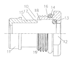
図1を参照すると、図1は、コネクタ本体1と、ケーブルクランプ部品2と、Vリング3と、平形ガスケット4と、クランプナット5とを含む現在使用されるRF同軸コネクタを示しており、それが使用されるときには、RF同軸ケーブルの一端の外側シールド層が除去されて外側導体が露出され、RF同軸ケーブルがクランプナット5、平形ガスケット、および、Vリング3によって順々に覆われ、Vリング3の切り欠きが平ワッシャ4と反対方向に向けられ、その後、外側導体が同時に外側シールド層の断面に寄り掛かる(prop)ケーブルクランプ部品2によって覆われ、Vリング3の切り欠きと対向するケーブルクランプ部品2の端面は、Vリング3の切り欠きと係合できる形態を有し、その後、外側導体が上方に折り曲げられて、露出された内側シールド層が除去され、それにより、中心導体が露出され、その後、この前記アセンブリがコネクタ本体1内に挿入されて、クランプナット5が回転され、ネジ螺合によりコネクタ本体1と接続される。この期間中、ケーブルクランプ部品2がVリング3の切り欠きにスナップ嵌合され、平形ガスケット4の2つの端部がクランプナット5およびVリング3のそれぞれと当接(prop)し、それにより、ケーブルクランプ部品2およびクランプナット5がシールされ、また、Vリング3の外面は、コネクタ本体1の内壁と当接して該内壁でシールでき、それにより、水がコネクタ内に入ることが防止される。
Referring to FIG. 1, FIG. 1 shows a currently used RF coaxial connector that includes a
しかしながら、前記コネクタ構造は以下の問題を有する。
1.前述したコネクタ構造は多部品構造であり、そのプロセスが複雑であるとともに、その製造コストおよび価格が高い。
However, the connector structure has the following problems.
1. The connector structure described above is a multi-part structure, and its process is complicated, and its manufacturing cost and price are high.
2.前述したコネクタ構造は多部品構造であるため、部品が容易に紛失され、これらの部品、特にVリング3および平形ガスケット4を屋外の設置において容易に見失う可能性があると同時に、設置時間が長い。
2. Since the connector structure described above is a multi-part structure, the parts can be easily lost, and these parts, particularly the V-
3.前述したコネクタ構造はVリング3を採用するため、Vリング3は、圧縮後に破壊され(2つの部品に分割され)、何度も設置できず、使用コストが高い。
3. Since the connector structure described above employs the V-
4.Vリング3の外面がコネクタ本体1の内壁と当接して該内壁でシールされるため、内壁と当接するのに不十分な力に起因して、シール効果が良好でない。
4). Since the outer surface of the V-
したがって、良好なシール効果を有するだけでなく、部品数も少なく、製造が容易であるとともに、製造コストが低く、その部品を容易に紛失できず、その設置時間が短く、それを繰り返し設置でき、また、その使用コストが低い、RF同軸コネクタの二重シール構造体を提供する必要がある。 Therefore, not only has a good sealing effect, the number of parts is small, the manufacturing is easy, the manufacturing cost is low, the parts can not be easily lost, the installation time is short, it can be repeatedly installed, There is also a need to provide a dual seal structure for RF coaxial connectors that is low in cost of use.
本発明の態様は、一般に、RF同軸コネクタの二重シール構造体および関連するRF同軸コネクタに関し、RF同軸コネクタの二重シール構造体は、巧みに設計され、良好なシール効果を有するだけでなく、部品数も少なく、製造が容易であるとともに、製造コストが低く、その部品を容易に紛失できず、その設置時間が短く、それを繰り返し設置でき、また、その使用コストが低く、したがって、本発明は大規模な普及に適している。 Aspects of the present invention generally relate to RF coaxial connector dual seal structures and related RF coaxial connectors, where the RF coaxial connector dual seal structure is not only well-designed and has a good sealing effect. The number of parts is small, the manufacturing is easy, the manufacturing cost is low, the parts cannot be easily lost, the installation time is short, it can be installed repeatedly, and the use cost is low, so The invention is suitable for large-scale spread.
前記目的を実現するため、本発明の第1の態様では、
RF同軸コネクタのコネクタ本体と接続されるべく使用されるクランプナットと、
クランプナット内に移動可能に配置される第1の端部を備えるケーブルクランプ部品と、
クランプナットの内側の面の内側に位置決めされ、第1の端部の端面とクランプナットの内壁との間に位置される第1のシールリングと、
クランプナットの外側の面に配置され、コネクタ本体でシールされるべく使用される第2のシールリングと、
を備えるRF同軸コネクタの二重シール構造体が提供される。
In order to achieve the above object, in the first aspect of the present invention,
A clamp nut used to be connected to the connector body of the RF coaxial connector;
A cable clamp component comprising a first end movably disposed within the clamp nut;
A first seal ring positioned inside the inner surface of the clamp nut and positioned between the end surface of the first end and the inner wall of the clamp nut;
A second seal ring disposed on the outer surface of the clamp nut and used to be sealed with the connector body;
A dual seal structure for an RF coaxial connector is provided.
更なる態様では、第1の端部は、クランプナットから離れる方向でクランプナットにより制限(restrict)される。 In a further aspect, the first end is restricted by the clamp nut in a direction away from the clamp nut.
更なる態様では、第1の端部とクランプナットとが圧入またはネジ接続で接続される。 In a further aspect, the first end and the clamp nut are connected by press fitting or screw connection.
更なる他の態様では、第1の凸部が第1の端部の外側の面に配置され、第2の凸部がクランプナットの内側の面に配置され、第1の凸部は、第2の凸部と第1のシールリングとの間に位置されて、クランプナットから離れる方向で第2の凸部により制限され、それにより、第1の端部とクランプナットとが圧入接続で接続される。 In still another aspect, the first convex portion is disposed on the outer surface of the first end portion, the second convex portion is disposed on the inner surface of the clamp nut, and the first convex portion is Is located between the second convex portion and the first seal ring, and is limited by the second convex portion in a direction away from the clamp nut, so that the first end portion and the clamp nut are connected by press-fit connection. Is done.
更なる他の態様では、第1のネジが第1の端部の外側の面に配置され、第2のネジがクランプナットの内側の面に配置され、第1のネジが第2のネジと螺合され、それにより、第1の端部とクランプナットとがネジ接続で接続される。 In yet another aspect, a first screw is disposed on the outer surface of the first end, a second screw is disposed on the inner surface of the clamp nut, and the first screw is the second screw. The first end and the clamp nut are connected by screw connection.
更なる態様にでは、クランプナットは、コネクタ本体と圧入またはネジ接続で接続されるべく使用される。 In a further aspect, the clamp nut is used to be connected to the connector body by press-fit or screw connection.
更なる他の態様では、コネクタ本体と圧入接続で接続されるべく使用される第3の凸部がクランプナットの外側の面に配置される。 In still another aspect, a third convex portion used to be connected to the connector body by press-fitting connection is disposed on the outer surface of the clamp nut.
更なる他の態様では、コネクタ本体とネジ接続で接続されるべく使用される第3のネジがクランプナットの外側の面に配置される。 In yet another aspect, a third screw used to be connected with the connector body in a screw connection is disposed on the outer surface of the clamp nut.
更なる態様にでは、第1のシールリングおよび第2のシールリングはそれぞれ、Oリング、長方形リング、および、正方形リングうちのいずれか1つである。 In a further aspect, the first seal ring and the second seal ring are each one of an O-ring, a rectangular ring, and a square ring.
本発明の第2の態様では、
RF同軸コネクタのコネクタ本体と圧入またはネジ接続で接続されるべく使用されるクランプナットと、
クランプナット内に移動可能に配置されてクランプナットから離れる方向でクランプナットにより制限される第1の端部を備えるケーブルクランプ部品と、
クランプナットの内側の面の内側に位置決めされ、第1の端部の端面とクランプナットの内壁との間に位置される第1のシールリングと、
クランプナットの外側の面に配置され、コネクタ本体でシールされるべく使用される第2のシールリングと、
を備えるRF同軸コネクタの二重シール構造体が提供される。
In the second aspect of the present invention,
A clamp nut used to be connected to the connector body of the RF coaxial connector by press-fitting or screw connection;
A cable clamp component comprising a first end movably disposed within the clamp nut and limited by the clamp nut in a direction away from the clamp nut;
A first seal ring positioned inside the inner surface of the clamp nut and positioned between the end surface of the first end and the inner wall of the clamp nut;
A second seal ring disposed on the outer surface of the clamp nut and used to be sealed with the connector body;
A dual seal structure for an RF coaxial connector is provided.
更なる態様では、第1の端部とクランプナットとが圧入またはネジ接続で接続される。 In a further aspect, the first end and the clamp nut are connected by press fitting or screw connection.
更なる他の態様では、第1の凸部が第1の端部の外側の面に配置され、第2の凸部がクランプナットの内側の面に配置され、第1の凸部は、第2の凸部と第1のシールリングとの間に位置されて、クランプナットから離れる方向で第2の凸部により制限され、それにより、第1の端部とクランプナットとが圧入接続で接続される。 In still another aspect, the first convex portion is disposed on the outer surface of the first end portion, the second convex portion is disposed on the inner surface of the clamp nut, and the first convex portion is Is located between the second convex portion and the first seal ring, and is limited by the second convex portion in a direction away from the clamp nut, so that the first end portion and the clamp nut are connected by press-fit connection. Is done.
更なる他の態様では、第1のネジが第1の端部の外側の面に配置され、第2のネジがクランプナットの内側の面に配置され、第1のネジが第2のネジと螺合され、それにより、第1の端部とクランプナットとがネジ接続で接続される。 In yet another aspect, a first screw is disposed on the outer surface of the first end, a second screw is disposed on the inner surface of the clamp nut, and the first screw is the second screw. The first end and the clamp nut are connected by screw connection.
更なる態様では、コネクタ本体と圧入接続で接続されるべく使用される第3の凸部がクランプナットの外側の面に配置される。 In a further aspect, a third convex portion used to be connected to the connector body by press-fitting connection is arranged on the outer surface of the clamp nut.
更なる態様では、コネクタ本体とネジ接続で接続されるべく使用される第3のネジがクランプナットの外側の面に配置される。 In a further aspect, a third screw used to be connected with the connector body in a screw connection is arranged on the outer surface of the clamp nut.
更なる態様では、第1のシールリングおよび第2のシールリングはそれぞれ、Oリング、長方形リング、および、正方形リングのうちのいずれか1つである。 In a further aspect, the first seal ring and the second seal ring are each one of an O-ring, a rectangular ring, and a square ring.
本発明の第3の態様では、
コネクタ本体と、
コネクタ本体と接続されるクランプナットと、
コネクタ本体内に位置され、クランプナット内に移動可能に配置される第1の端部を備えるケーブルクランプ部品と、
クランプナットの内側の面の内側に位置決めされ、第1の端部の端面とクランプナットの内壁との間に位置される第1のシールリングと、
クランプナットの外側の面に配置され、コネクタ本体でシールされる第2のシールリングと、
を備えるRF同軸コネクタが提供される。
In the third aspect of the present invention,
A connector body;
A clamp nut connected to the connector body;
A cable clamp component comprising a first end positioned within the connector body and movably disposed within the clamp nut;
A first seal ring positioned inside the inner surface of the clamp nut and positioned between the end surface of the first end and the inner wall of the clamp nut;
A second seal ring disposed on the outer surface of the clamp nut and sealed by the connector body;
An RF coaxial connector is provided.
更なる態様では、第1の端部は、クランプナットから離れる方向でクランプナットにより制限される。 In a further aspect, the first end is limited by the clamp nut in a direction away from the clamp nut.
更なる態様では、第1の端部とクランプナットとが圧入またはネジ接続で接続される。 In a further aspect, the first end and the clamp nut are connected by press fitting or screw connection.
更なる他の態様では、第1の凸部が第1の端部の外側の面に配置され、第2の凸部がクランプナットの内側の面に配置され、第1の凸部は、第2の凸部と第1のシールリングとの間に位置されて、クランプナットから離れる方向で第2の凸部により制限され、それにより、第1の端部とクランプナットとが圧入接続で接続される。 In still another aspect, the first convex portion is disposed on the outer surface of the first end portion, the second convex portion is disposed on the inner surface of the clamp nut, and the first convex portion is Is located between the second convex portion and the first seal ring, and is limited by the second convex portion in a direction away from the clamp nut, so that the first end portion and the clamp nut are connected by press-fit connection. Is done.
更なる他の態様では、第1のネジが第1の端部の外側の面に配置され、第2のネジがクランプナットの内側の面に配置され、第1のネジが第2のネジと螺合され、それにより、第1の端部とクランプナットとがネジ接続で接続される。 In yet another aspect, a first screw is disposed on the outer surface of the first end, a second screw is disposed on the inner surface of the clamp nut, and the first screw is the second screw. The first end and the clamp nut are connected by screw connection.
更なる態様では、クランプナットがコネクタ本体と圧入またはネジ接続で接続される。 In a further aspect, the clamp nut is connected to the connector body by press-fitting or screw connection.
更なる他の態様では、第3の凸部がクランプナットの外側の面に配置され、第4の凸部がコネクタ本体の内面に配置され、第3の凸部は、第4の凸部とコネクタ本体の内部との間に位置されて、コネクタ本体から離れる方向で第4の凸部により制限され、それにより、クランプナットとコネクタ本体とが圧入接続で接続される。 In still another aspect, the third convex portion is disposed on the outer surface of the clamp nut, the fourth convex portion is disposed on the inner surface of the connector main body, and the third convex portion is the fourth convex portion. It is located between the inside of the connector body and restricted by the fourth convex portion in the direction away from the connector body, whereby the clamp nut and the connector body are connected by press-fit connection.
更なる他の態様では、第3のネジがクランプナットの外側の面に配置され、第4のネジがコネクタ本体の内面に配置され、第3のネジが第4のネジと螺合され、それにより、クランプナットとコネクタ本体とがネジ接続で接続される。 In yet another aspect, the third screw is disposed on the outer surface of the clamp nut, the fourth screw is disposed on the inner surface of the connector body, and the third screw is threadedly engaged with the fourth screw. Thus, the clamp nut and the connector main body are connected by screw connection.
本発明の有利な効果は以下の通りである。
1.本発明のRF同軸コネクタの二重シール構造体は、ケーブルクランプ部品と、クランプナットと、第1のシールリングと、第2のシールリングとを備え、ケーブルクランプ部品は、クランプナット内に移動可能に配置される第1の端部を備え、第1のシールリングは、クランプナットの内側の面の内側に位置決めされるとともに、第1の端部の端面とクランプナットの内壁との間に位置され、第2のシールリングはクランプナットの外側の面に配置され、それにより、第2のシールリングがクランプナットとコネクタ本体とをシールするために使用され、第1のシールリングがクランプナットおよびケーブルをシールするために使用され、その結果、二重シールが達成され、したがって、RF同軸コネクタの二重シール構造体は、巧みに設計され、良好なシール効果を有するだけでなく、部品数も少なく、製造が容易であるとともに、製造コストが低く、それを繰り返し設置でき、また、その使用コストが低く、そのため、本発明は大規模な普及に適している。
Advantageous effects of the present invention are as follows.
1. The double seal structure of the RF coaxial connector of the present invention includes a cable clamp part, a clamp nut, a first seal ring, and a second seal ring, and the cable clamp part is movable in the clamp nut. The first seal ring is positioned inside the inner surface of the clamp nut, and is positioned between the end surface of the first end and the inner wall of the clamp nut. And the second seal ring is disposed on the outer surface of the clamp nut, whereby the second seal ring is used to seal the clamp nut and the connector body, and the first seal ring is the clamp nut and Used to seal the cable, so that a double seal is achieved, therefore the double seal structure of the RF coaxial connector is cleverly designed In addition to having a good sealing effect, the number of parts is small, the manufacturing is easy, the manufacturing cost is low, it can be repeatedly installed, and the use cost is low. Suitable for widespread use.
2.本発明のRF同軸コネクタの二重シール構造体のケーブルクランプ部品は、クランプナットから離れる方向でクランプナットにおいてクランプナットにより制限されて、クランプナットと共に一体部品を形成することができ、したがって、RF同軸コネクタの二重シール構造体の部品は、容易に紛失することができず、RF同軸コネクタの二重シール構造体の設置時間が短く、そのため、RF同軸コネクタの二重シール構造体は大規模な普及に適している。 2. The cable clamp component of the dual seal structure of the RF coaxial connector of the present invention can be constrained by the clamp nut at the clamp nut in a direction away from the clamp nut to form an integral component with the clamp nut, and thus RF coaxial. The parts of the double seal structure of the connector cannot be easily lost, and the installation time of the double seal structure of the RF coaxial connector is short, so that the double seal structure of the RF coaxial connector is large. Suitable for popularization.
3.本発明のRF同軸コネクタの二重シール構造体のケーブルクランプ部品が、長手方向に回転でき且つクランプナットにおいて軸方向で制限されて、クランプナットと共に1つの部品、すなわち、一体構造を形成すると、RF同軸コネクタの二重シール構造体が更なる利点を有する。すなわち、クランプナットをケーブルクランプ部品に対して自由に独立に回転でき、また、ケーブルクランプ部品は、ケーブルを位置決めしてクランプナットの回転に追従してケーブルが回転するのを防止するために使用され、したがって、RF同軸コネクタの二重シール構造体は大規模な普及に適している。 3. When the cable clamp component of the dual seal structure of the RF coaxial connector of the present invention can be rotated in the longitudinal direction and restricted axially at the clamp nut to form a single component, ie, a unitary structure with the clamp nut, RF The double seal structure of the coaxial connector has further advantages. That is, the clamp nut can rotate freely and independently with respect to the cable clamp component, and the cable clamp component is used to position the cable and follow the rotation of the clamp nut to prevent the cable from rotating. Therefore, the double seal structure of the RF coaxial connector is suitable for large-scale spread.
本発明の技術内容を明確に理解するために、以下の実施例を参照することにより本発明を更に例示する。 In order to clearly understand the technical contents of the present invention, the present invention is further illustrated by reference to the following examples.
図2−図4を参照すると、本発明のRF同軸コネクタの二重シール構造体10は、ケーブルクランプ部品11、RF同軸コネクタのコネクタ本体20と接続されるべく使用されるクランプナット12、第1のシールリング13、および、第2のシールリング14を備え、ケーブルクランプ部品11はクランプナット12内に移動可能に配置される第1の端部15を備え、第1のシールリング13は、クランプナット12の内側の面の内側に位置決めされるとともに、第1の端部15の端面とクランプナット12の内壁との間に位置され、第2のシールリング14は、クランプナット12の外側の面に配置されて、コネクタ本体20でシールされるべく使用される。
2 to 4, the
好ましくは、図2−図5Bに示されるように、クランプナット12の外側の面に溝16を設けることができ、溝16内に第2のシールリング14が位置される。
Preferably, as shown in FIGS. 2 to 5B, a
第1のシールリング13および第2のシールリング14は、任意の形状を有するシールリングであってもよく、また、規則的なシールリングまたは不規則なシールリングであってもよい。第1のシールリング13および第2のシールリング14はそれぞれ、Oリング、長方形リング、および、正方形リングのうちのいずれかであることが好ましい。図3および図4を参照すると、本発明の一実施形態では、第1のシールリング13および第2のシールリング14のいずれもOリングである。
The
第1のシールリング13および第2のシールリング14の材料は、任意の適した材料、例えば、シリコーンゴム、EPDM、ニトリルゴム、および、シールのために使用できる全ての材料であってもよく、材料は、適切な圧縮率、例えば一般的には20%〜30%の圧縮率を有するのが好ましい。Oリングの場合、圧縮率の計算式は以下の通りである。
W=(d0−h)/d0×100%
The material of the
W = (d 0 −h) / d 0 × 100%
ここで、d0:自由状態下のOリングの断面の直径(mm)、h:Oリングの溝の底部の距離、すなわち、圧縮されたOリングの断面の高さ(mm)である。 Where d 0 is the diameter (mm) of the cross section of the O-ring under free condition, and h is the distance of the bottom of the groove of the O-ring, that is, the height (mm) of the cross section of the compressed O-ring.
第1の端部15をクランプナット12から離れる方向でクランプナット12により制限することができない。第1の端部15は、クランプナット12から離れる方向でクランプナット12により制限されるのが好ましい。したがって、ケーブルクランプ部品11は、クランプナット12から分離されずに、クランプナット12と共に1つの部品、すなわち、一体構造を形成する。
The
第1の端部15およびクランプナット12を任意の適した方法で接続することができる。第1の端部15およびクランプナット12は圧入接続で接続されることが好ましい。図2、図5A、および、図5Bを参照すると、本発明の一実施形態では、第1の凸部17が第1の端部15の外側の面に配置され、第2の凸部18がクランプナット12の内側の面に配置され、第1の凸部17は、第2の凸部18と第1のシールリング13との間に位置されて、クランプナット12から離れる方向で第2の凸部18により制限され、それにより、第1の端部15とクランプナット12とが圧入接続で接続される。このように、ケーブルクランプ部品11の第1の端部15がクランプナット12内にスナップ嵌合され、ケーブルクランプ部品11は、長手方向に回転できるとともに、クランプナット12内で軸方向に制限され、それにより、クランプナット12と共に1つの部品、すなわち、一体構造を形成し、一人の顧客にとって、自分が得るケーブル設置アセンブリ、すなわち、本発明は、1つの部品だけを有し、ケーブル設置時間を短縮するだけでなく、顧客は部品の紛失を心配せず、設置が容易であり、また、部品を簡単には紛失せず、第2に、クランプナット12はケーブルクランプ部品11に対して自由に独立に回転でき、また、ケーブルクランプ部品11は、ケーブルを位置決めしてクランプナット12の回転に追従してケーブルが回転するのを防止するために使用される。
The
第1の端部15とクランプナット12とをネジ接続で接続することもできる。例えば、第1のネジ(図示せず)が第1の端部15の外側の面に配置され、第2のネジ(図示せず)がクランプナット12の内側の面に配置され、第1のネジが第2のネジと螺合され、それにより、第1の端部15とクランプナット12とがネジ接続で接続される。また、ケーブルクランプ部品11とクランプナット12とが1つの部品、すなわち、一体構造を形成することを達成することもできる。
It is also possible to connect the
クランプナット12とコネクタ本体20とを接続するために任意の適した方法を採用することができる。クランプナット12は、コネクタ本体20とネジ接続で接続されるべく使用されるのが好ましい。図2、図5A、および、図5Bを参照すると、本発明の一実施形態では、コネクタ本体20とネジ接続で接続されるべく使用される第3のネジ19がクランプナット12の外側の面に配置される。図6、図8、および、図9を参照すると、これに対応して、第4のネジ21がコネクタ本体20の内面に配置され、この第4のネジは、クランプナット12の外側の面の第3のネジ19と螺合されるべく使用される。
Any suitable method may be employed to connect the
また、クランプナット12をコネクタ本体20と圧入接続で接続させることもできる。例えば、コネクタ本体20と圧入接続で接続されるべく使用される第3の凸部(図示せず)がクランプナット12の外側の面に配置される。これに対応して、第4の凸部(図示せず)がコネクタ本体20の内面に配置され、クランプナット12の外側の面の第3の凸部がコネクタ本体20内にスナップ嵌合されると、コネクタ本体20の内面の第4の凸部がクランプナット12の外側の面の第3の凸部を制限し、それにより、クランプナット12がコネクタ本体20から分離されるのが防止される。
Further, the
図3−図5Bを参照すると、本発明のRF同軸コネクタの二重シール構造体10が組み付けられる際には、第1のシールリング13および第2のシールリング14がクランプナット12の内側の面の内側および外側の面にそれぞれ位置され、その後、ケーブルクランプ部品11の第1の端部15がクランプナット12内に圧入され、圧入期間中に第1の凸部17が第2の凸部18と接触するときに第1の凸部17および第2の凸部18が特定の度合いまで変形され、その結果、第1の凸部17が第2の凸部18を通過してクランプナット12内に押し込まれ(squeezed)、その後、これらの凸部がそれらの当初の状態へ戻り、それにより、第2の凸部18による第1の凸部17の制限が達成される。
Referring to FIGS. 3 to 5B, when the
図6を参照すると、本発明の二重シール構造体10とRF同軸コネクタのコネクタ本体20とが接続される際には、ケーブルクランプ部品11がコネクタ本体20の前方に挿入され、その後、クランプナット12が回転されて、クランプナット12の第3のネジ19とコネクタ本体20の第4のネジ21とのネジ螺合により本発明のRF同軸コネクタの二重シール構造体10がコネクタ本体20内に固定される。
Referring to FIG. 6, when the
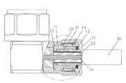
図7−図9を参照すると、特定の用途では、RF同軸ケーブル30の一端の外側シールド層31が除去されて外側導体32が露出され、RF同軸ケーブル30が本発明によって覆われる。この場合、外側導体は、外側シールド層31の断面に寄り掛かるケーブルクランプ部品11によって覆われ、その後、外側導体32が上方に折り曲げられ、露出された内側シールド層33が除去され、それにより、中心導体34が露出され、その後、この前記アセンブリがコネクタ本体20内に挿入されて、クランプナット5が回転され、ネジ螺合によりコネクタ本体20と接続される。
7-9, in certain applications, the outer shield layer 31 at one end of the RF
図9を参照すると、二重シール構造体10と本発明のRF同軸コネクタのコネクタ本体20とが接続される際には、第1のシールシング13が、ケーブルクランプ部品11とクランプナット12との間に位置されて、ケーブルクランプ部品11およびクランプナット12のそれぞれに当接し、それにより、クランプナット12およびRF同軸ケーブル30をシールするための第1のシールが形成され、また、第2のシールリング14が、コネクタ本体20とクランプナット12との間に位置されて、コネクタ本体20およびクランプナット12のそれぞれに当接し、それにより、クランプナット12およびコネクタ本体20をシールするための第2のシールが形成され、二重シールに起因してシール効果が顕著である。二重シールリングは設置時に破壊されないため、これらのシールリングを何度も取り付けることができる。
Referring to FIG. 9, when the
要約すれば、本発明のRF同軸コネクタの二重シール構造体は、巧みに設計され、良好なシール効果を有するだけでなく、部品数も少なく、製造が容易であるとともに、製造コストが低く、その部品を容易に紛失できず、その設置時間が短く、それを繰り返し設置でき、また、その使用コストが低く、したがって、本発明は大規模な普及に適している。 In summary, the dual seal structure of the RF coaxial connector of the present invention is skillfully designed and not only has a good sealing effect, but also has a small number of parts, is easy to manufacture, and has a low manufacturing cost. The part cannot be easily lost, its installation time is short, it can be installed repeatedly, and its use cost is low, so the present invention is suitable for large scale spread.
この明細書では、特定の実施形態にしたがって本発明を説明してきた。しかし、本発明の思想および範囲から逸脱することなくこれらの実施形態を改良しまたは変更できるのは言うまでもない。したがって、前述の説明および図面は単なる例示であって限定しようとするものではない。 In this specification, the invention has been described with reference to specific embodiments. However, it will be appreciated that these embodiments may be improved or modified without departing from the spirit and scope of the invention. Accordingly, the foregoing description and drawings are illustrative only and are not intended to be limiting.
10 二重シール構造体(dual sealing structure)
11 ケーブルクランプ部品(cable clamping component)
12 クランプナット(clamping nut)
13 第1のシールリング(first sealing ring)
14 第2のシールリング(second sealing ring)
15 第1の端部(first end)
17 第1の凸部(first convex part)
18 第2の凸部(second convex part)
19 第3のネジ(third thread)
20 コネクタ本体(connector main body)
10 Dual sealing structure
11 Cable clamping component
12 Clamping nut
13 First sealing ring
14 Second sealing ring
15 first end
17 First convex part
18 Second convex part (second convex part)
19 Third thread
20 Connector main body
Claims (24)
前記クランプナット内に移動可能に配置される第1の端部を備えるケーブルクランプ部品と、
前記クランプナットの内側の面の内側に位置決めされ、前記第1の端部の端面と前記クランプナットの内壁との間に位置される第1のシールリングと、
前記クランプナットの外側の面に配置され、前記コネクタ本体でシールされるべく使用される第2のシールリングと、
を備えるRF同軸コネクタの二重シール構造体。 A clamp nut used to be connected to the connector body of the RF coaxial connector;
A cable clamp component comprising a first end movably disposed within the clamp nut;
A first seal ring positioned inside an inner surface of the clamp nut and positioned between an end surface of the first end and an inner wall of the clamp nut;
A second seal ring disposed on an outer surface of the clamp nut and used to be sealed with the connector body;
An RF coaxial connector double seal structure comprising:
前記クランプナット内に移動可能に配置されて前記クランプナットから離れる方向で前記クランプナットにより制限される第1の端部を備えるケーブルクランプ部品と、
前記クランプナットの内側の面の内側に位置決めされ、前記第1の端部の端面と前記クランプナットの内壁との間に位置される第1のシールリングと、
前記クランプナットの外側の面に配置され、前記コネクタ本体でシールされるべく使用される第2のシールリングと、
を備えるRF同軸コネクタの二重シール構造体。 A clamp nut used to be connected to the connector body of the RF coaxial connector by press-fitting or screw connection;
A cable clamp component comprising a first end movably disposed within the clamp nut and limited by the clamp nut in a direction away from the clamp nut;
A first seal ring positioned inside an inner surface of the clamp nut and positioned between an end surface of the first end and an inner wall of the clamp nut;
A second seal ring disposed on an outer surface of the clamp nut and used to be sealed with the connector body;
An RF coaxial connector double seal structure comprising:
前記コネクタ本体と接続されるクランプナットと、
前記コネクタ本体内に位置され、前記クランプナット内に移動可能に配置される第1の端部を備えるケーブルクランプ部品と、
前記クランプナットの内側の面の内側に位置決めされ、前記第1の端部の端面と前記クランプナットの内壁との間に位置される第1のシールリングと、
前記クランプナットの外側の面に配置され、前記コネクタ本体でシールされる第2のシールリングと、
を備えるRF同軸コネクタ。 A connector body;
A clamp nut connected to the connector body;
A cable clamp component comprising a first end positioned within the connector body and movably disposed within the clamp nut;
A first seal ring positioned inside an inner surface of the clamp nut and positioned between an end surface of the first end and an inner wall of the clamp nut;
A second seal ring disposed on an outer surface of the clamp nut and sealed by the connector body;
RF coaxial connector comprising:
Applications Claiming Priority (2)
| Application Number | Priority Date | Filing Date | Title |
|---|---|---|---|
| CN2011100429672A CN102176581A (en) | 2011-02-22 | 2011-02-22 | Double-sealing structure of radio frequency coaxial connector and related radio frequency coaxial connector |
| CN201110042967.2 | 2011-02-22 |
Publications (1)
| Publication Number | Publication Date |
|---|---|
| JP2012174694A true JP2012174694A (en) | 2012-09-10 |
Family
ID=44519701
Family Applications (1)
| Application Number | Title | Priority Date | Filing Date |
|---|---|---|---|
| JP2012036842A Pending JP2012174694A (en) | 2011-02-22 | 2012-02-22 | Double seal structure of rf coaxial connector and related rf coaxial connector |
Country Status (4)
| Country | Link |
|---|---|
| US (1) | US20120214341A1 (en) |
| JP (1) | JP2012174694A (en) |
| CN (1) | CN102176581A (en) |
| DE (1) | DE102012003362A1 (en) |
Cited By (6)
| Publication number | Priority date | Publication date | Assignee | Title |
|---|---|---|---|---|
| CN103367994A (en) * | 2013-07-16 | 2013-10-23 | 镇江中信电子有限公司 | Stepped sealing cable connector |
| CN103407146A (en) * | 2013-08-07 | 2013-11-27 | 安徽省新方尊铸造科技有限公司 | Method for prolonging service life of sleeve of screw |
| CN105161903A (en) * | 2015-06-26 | 2015-12-16 | 上海航天科工电器研究院有限公司 | Waterproof connector for connecting cables |
| CN105826750A (en) * | 2016-05-12 | 2016-08-03 | 杭州航天电子技术有限公司 | Sealing structure of electric connector wire outlet capable of superposition |
| CN108565597A (en) * | 2018-04-04 | 2018-09-21 | 江苏华吉通信科技有限公司 | A kind of mounting structure of efficient radio frequency (RF) coaxial connector |
| JP2020113478A (en) * | 2019-01-15 | 2020-07-27 | 住友電装株式会社 | connector |
Families Citing this family (15)
| Publication number | Priority date | Publication date | Assignee | Title |
|---|---|---|---|---|
| US8328577B1 (en) * | 2011-10-15 | 2012-12-11 | Yueh Chiung Lu | Coaxial cable connector |
| US8529294B2 (en) * | 2011-12-15 | 2013-09-10 | Tyco Electronics Corporation | Coaxial connector with coupling nut |
| DE202013002575U1 (en) * | 2013-03-15 | 2013-04-17 | Rosenberger Hochfrequenztechnik Gmbh & Co. Kg | Connectors |
| US10404048B2 (en) * | 2013-11-26 | 2019-09-03 | Commscope Technologies Llc | Adapter for sealing cover for electrical interconnections |
| CN105098462A (en) * | 2014-04-24 | 2015-11-25 | 泰科电子(上海)有限公司 | Connector, matching connector and connector combination |
| DE102015100276A1 (en) * | 2015-01-09 | 2016-07-14 | dEE dieEntwickler Elektronik GmbH | Device for contacting an electronic device, and electrical device |
| WO2016149329A1 (en) * | 2015-03-16 | 2016-09-22 | Commscope Technologies Llc | Right angle coaxial cable and connector assembly and method of forming same |
| CN104991322B (en) * | 2015-06-24 | 2018-08-10 | 中航光电科技股份有限公司 | A kind of optical connector |
| CN104991321B (en) * | 2015-06-24 | 2018-08-10 | 中航光电科技股份有限公司 | A kind of multifibre joint |
| CN107800009B (en) * | 2017-09-28 | 2023-09-29 | 江苏亨鑫科技有限公司 | Quick installation mechanism of radio frequency coaxial cable connector |
| CN107742801A (en) * | 2017-10-17 | 2018-02-27 | 江苏永沃铜业有限公司 | A kind of push-in radio frequency connector |
| CN107834321A (en) * | 2017-10-18 | 2018-03-23 | 江苏永沃铜业有限公司 | A kind of Portable easily-mountable radio-frequency connector |
| CN108123285A (en) * | 2018-01-29 | 2018-06-05 | 上海哲宏机器人自动化有限公司 | A kind of water proof type encoder for servo motor cable connector |
| CN109004324A (en) * | 2018-07-27 | 2018-12-14 | 安徽禄讯电子科技有限公司 | A kind of connector of power splitter |
| CN112993650B (en) * | 2021-02-06 | 2022-06-21 | 湖北云万光电子科技有限公司 | Take POE network transmission single waterproof connector |
Family Cites Families (18)
| Publication number | Priority date | Publication date | Assignee | Title |
|---|---|---|---|---|
| US3678446A (en) * | 1970-06-02 | 1972-07-18 | Atomic Energy Commission | Coaxial cable connector |
| US4046451A (en) * | 1976-07-08 | 1977-09-06 | Andrew Corporation | Connector for coaxial cable with annularly corrugated outer conductor |
| DE69734971T2 (en) * | 1996-10-23 | 2006-06-22 | Thomas & Betts International Inc., Sparks | coaxial cable |
| SE9800448L (en) * | 1998-02-17 | 1999-04-12 | Teracom Components Ab | Contact device for high frequency cables |
| US6109964A (en) * | 1998-04-06 | 2000-08-29 | Andrew Corporation | One piece connector for a coaxial cable with an annularly corrugated outer conductor |
| DE69828400T2 (en) * | 1998-10-13 | 2005-12-01 | Cabel-Con A/S | Connector for coaxial cable with friction lock |
| US6386915B1 (en) * | 2000-11-14 | 2002-05-14 | Radio Frequency Systems, Inc. | One step connector |
| US6910910B2 (en) * | 2003-08-26 | 2005-06-28 | Ocean Design, Inc. | Dry mate connector |
| US7261581B2 (en) * | 2003-12-01 | 2007-08-28 | Corning Gilbert Inc. | Coaxial connector and method |
| US6955562B1 (en) * | 2004-06-15 | 2005-10-18 | Corning Gilbert Inc. | Coaxial connector with center conductor seizure |
| WO2007019141A1 (en) * | 2005-08-04 | 2007-02-15 | Parker-Hannifin Corporation | Pre-assemblable, push-in fitting connection for corrugated tubing |
| DE102006012435A1 (en) * | 2006-03-17 | 2007-09-20 | Amphenol-Tuchel Electronics Gmbh | Cable gland and sealing element for this |
| US7465190B2 (en) * | 2006-06-29 | 2008-12-16 | Corning Gilbert Inc. | Coaxial connector and method |
| US8075337B2 (en) * | 2008-09-30 | 2011-12-13 | Belden Inc. | Cable connector |
| KR101166086B1 (en) * | 2009-01-13 | 2012-07-23 | 엘에스전선 주식회사 | Connector for coaxial cable |
| US8025518B2 (en) * | 2009-02-24 | 2011-09-27 | Corning Gilbert Inc. | Coaxial connector with dual-grip nut |
| US7803018B1 (en) * | 2009-03-10 | 2010-09-28 | Andrew Llc | Inner conductor end contacting coaxial connector and inner conductor adapter kit |
| US8038472B2 (en) * | 2009-04-10 | 2011-10-18 | John Mezzalingua Associates, Inc. | Compression coaxial cable connector with center insulator seizing mechanism |
-
2011
- 2011-02-22 CN CN2011100429672A patent/CN102176581A/en active Pending
-
2012
- 2012-02-09 US US13/369,531 patent/US20120214341A1/en not_active Abandoned
- 2012-02-22 JP JP2012036842A patent/JP2012174694A/en active Pending
- 2012-02-22 DE DE102012003362A patent/DE102012003362A1/en not_active Withdrawn
Cited By (10)
| Publication number | Priority date | Publication date | Assignee | Title |
|---|---|---|---|---|
| CN103367994A (en) * | 2013-07-16 | 2013-10-23 | 镇江中信电子有限公司 | Stepped sealing cable connector |
| CN103407146A (en) * | 2013-08-07 | 2013-11-27 | 安徽省新方尊铸造科技有限公司 | Method for prolonging service life of sleeve of screw |
| CN103407146B (en) * | 2013-08-07 | 2015-11-25 | 安徽省新方尊自动化科技有限公司 | A kind of method improving screw sleeve service life |
| CN105161903A (en) * | 2015-06-26 | 2015-12-16 | 上海航天科工电器研究院有限公司 | Waterproof connector for connecting cables |
| CN105826750A (en) * | 2016-05-12 | 2016-08-03 | 杭州航天电子技术有限公司 | Sealing structure of electric connector wire outlet capable of superposition |
| CN105826750B (en) * | 2016-05-12 | 2018-05-29 | 杭州航天电子技术有限公司 | A kind of stackable electric connector outlet port sealing structure |
| CN108565597A (en) * | 2018-04-04 | 2018-09-21 | 江苏华吉通信科技有限公司 | A kind of mounting structure of efficient radio frequency (RF) coaxial connector |
| CN108565597B (en) * | 2018-04-04 | 2024-02-02 | 广东汉立电气科技有限公司 | Efficient mounting structure of radio frequency coaxial connector |
| JP2020113478A (en) * | 2019-01-15 | 2020-07-27 | 住友電装株式会社 | connector |
| JP7147572B2 (en) | 2019-01-15 | 2022-10-05 | 住友電装株式会社 | connector |
Also Published As
| Publication number | Publication date |
|---|---|
| CN102176581A (en) | 2011-09-07 |
| US20120214341A1 (en) | 2012-08-23 |
| DE102012003362A1 (en) | 2012-08-23 |
Similar Documents
| Publication | Publication Date | Title |
|---|---|---|
| JP2012174694A (en) | Double seal structure of rf coaxial connector and related rf coaxial connector | |
| US9859662B2 (en) | Grounding for electrical connections | |
| US8602795B2 (en) | Electrical connector | |
| TWI624125B (en) | Coaxial cable connector with continuity member | |
| KR20120008794U (en) | Cable connector joint fastening structure | |
| US11223174B2 (en) | Electrical connection device | |
| JP6726263B2 (en) | Plug connector | |
| CN210535916U (en) | Waterproof electric connector | |
| JP2016509362A (en) | Plug-in connector | |
| CN204011943U (en) | A kind of wire and cable connector | |
| JP3175239U (en) | Coaxial cable connector structure | |
| JP2007042415A (en) | Coaxial connector | |
| CN206301979U (en) | High-voltage connector | |
| CN103682815B (en) | A kind of cluster connector | |
| CN202418589U (en) | Sealing element | |
| US10615531B2 (en) | Socket having conductive terminals for connectors | |
| CN111355098A (en) | Mining explosion-proof high-voltage cable connector | |
| KR20150072189A (en) | Connecter | |
| RU133981U1 (en) | HIGH VOLTAGE CONNECTOR | |
| CN210129727U (en) | Waterproof connector structure | |
| CN216794090U (en) | Watertight socket assembly and underwater equipment | |
| CN202797360U (en) | Multi-contact connector for continuous coaxial cables | |
| TWI759038B (en) | Connector assembly and its connector | |
| CN211017606U (en) | Explosion-proof 19 core connector | |
| CN214798079U (en) | Multi-core connector |