JP2012172575A - Stator vane cascade - Google Patents
Stator vane cascade Download PDFInfo
- Publication number
- JP2012172575A JP2012172575A JP2011034515A JP2011034515A JP2012172575A JP 2012172575 A JP2012172575 A JP 2012172575A JP 2011034515 A JP2011034515 A JP 2011034515A JP 2011034515 A JP2011034515 A JP 2011034515A JP 2012172575 A JP2012172575 A JP 2012172575A
- Authority
- JP
- Japan
- Prior art keywords
- stationary blade
- hook
- individualized
- blade row
- band
- Prior art date
- Legal status (The legal status is an assumption and is not a legal conclusion. Google has not performed a legal analysis and makes no representation as to the accuracy of the status listed.)
- Pending
Links
Images


Abstract
Description
本発明は、静翼列部に関するものである。 The present invention relates to a stationary blade row portion.
軸流圧縮機の性能向上のためには、静止翼の翼厚の低減、内径側へ流路面を形成する部品を設けることが考えられる。
しかし、これらの構造は 固有振動数の低下を招くため、そのままでは、空力励振力と共振し、部品の破損に到る危険がある。
In order to improve the performance of the axial compressor, it is conceivable to reduce the blade thickness of the stationary blade and to provide a part that forms the flow path surface on the inner diameter side.
However, these structures cause a decrease in the natural frequency, and as such, there is a risk of resonating with the aerodynamic excitation force and resulting in damage to the parts.
このような問題を解決するために、例えば特許文献1に示すように、内外径の流路面を構成する部品を周方向に連なる帯(バンド)とし、それに翼を組み付けることで剛性を向上させて共振回避する構造(連翼構造)が広く用いられている。
In order to solve such a problem, for example, as shown in
一方、インナーバンドの一部を構成する個片化インナーバンドと、アウターバンドの一部を構成するアウターバンドと、上記インナーバンド及び上記アウターバンドに狭持される静翼とを有する個片化ユニットを接続することによって静翼列部を構成する技術が、特許文献2や特許文献3に開示されている。
例えば特許文献2に開示された発明は、高温部での熱応力の緩和を目的とし、隣接する部品との位置関係が拘束されることを防止する構造である。
この特許文献2に開示された発明は 隣接する部品との相対位置に関して、径方向のみを拘束するが、周方向には拘束させず摺動しうる構造となっている。
On the other hand, an individualized unit having an individualized inner band that constitutes a part of the inner band, an outer band that constitutes a part of the outer band, and a stationary blade sandwiched between the inner band and the outer
For example, the invention disclosed in
The invention disclosed in
また、特許文献3に開示された発明は、回転体の回転数上昇過程におけるシュラウド部分の捻れ変形により、隣接する部品と一体化することに特徴がある。すなわち、捻れ変形により発生する押し付け力が位置関係を拘束する。そのため、回転体であり、かつ必要な捻れ変形を許容できる構造である必要があり、また、拘束方向は反力に平行な方向に限定されている。
この特許文献3に開示された発明は 隣接する部品との相対位置に関して、捻れ反力に平行な方向のみを拘束し、その鉛直方向 および、径方向に対しては摺動可能で完全には拘束されない。
Further, the invention disclosed in
The invention disclosed in
特許文献1に示される構造の問題点として、構成部品を個別に製造して接合するため、各部品に付与される加工代の分、廃棄される製造余肉が増えること、また、部品を接合する分だけ製造コストが増えることがあった。
As a problem of the structure shown in
素材余肉、製造コストの低減を図るには、翼一枚とそれに対応する内外径の流路面を一体の構造(単翼構造)とすることが望ましく、特許文献2及び特許文献3に示すように個片化ユニットを用いることが望ましい。しかしながら、特許文献2,3の構造では固有振動数の低下を防ぐことは難しい。
In order to reduce the material surplus and the manufacturing cost, it is desirable that one blade and the corresponding inner and outer diameter flow path surfaces have an integrated structure (single blade structure), as shown in
本発明は、上述する問題点に鑑みてなされたもので、製造コストの低減を図ると共に固有振動数の低下を防ぐことを目的とする。 The present invention has been made in view of the above-described problems, and aims to reduce the manufacturing cost and prevent the natural frequency from decreasing.
本発明は、上記課題を解決するための手段として、以下の構成を採用する。 The present invention adopts the following configuration as means for solving the above-described problems.
第1の発明は、 インナーバンドの一部を構成する個片化インナーバンドと、アウターバンドの一部を構成するアウターバンドと、上記インナーバンド及び上記アウターバンドに狭持される静翼とを有する個片化ユニットを周方向に複数接続することによって構成される静翼列部であって、各個片化ユニットが開口部と係合部からなるフック部を有し、当該フック部同士を係合することによって隣り合う個片化ユニット同士が接続されているという構成を採用する。 1st invention has the separated inner band which comprises a part of inner band, the outer band which comprises a part of outer band, and the stationary blade clamped by the said inner band and the said outer band A stationary blade row part formed by connecting a plurality of individualized units in the circumferential direction, each individualized unit having a hook part composed of an opening part and an engaging part, and engaging the hook parts with each other By doing so, a configuration in which adjacent individualized units are connected is adopted.
第2の発明は、上記第1の発明において、フック部同士が係合した際に相手のフック部に当接することによって相手のフック部を拘束する拘束面を上記フック部が上記周方向に複数備え、フック部は開口側に向かうにつれて幅が大きくなっているという構成を採用する。 According to a second aspect of the present invention, in the first aspect of the present invention, when the hook portions are engaged with each other, a plurality of restraining surfaces that restrain the counterpart hook portion by contacting the counterpart hook portion are provided in the circumferential direction. The hook portion is configured such that the width increases toward the opening side.
本発明によれば、個片化ユニット同士を強固に固定することで剛性が向上して固有振動数の低下を防ぐことができる。
また、本発明によれば、個片化ユニットの形状を単純化して製造コストの低減を図ることができる。
According to the present invention, the individualized units are firmly fixed to each other, thereby improving the rigidity and preventing the natural frequency from being lowered.
In addition, according to the present invention, the shape of the singulated unit can be simplified to reduce the manufacturing cost.
以下、図面を参照して、本発明に係る静翼列部の一実施形態について説明する。なお、以下の図面において、各部材を認識可能な大きさとするために、各部材の縮尺を適宜変更している。 Hereinafter, an embodiment of a stationary blade row part according to the present invention will be described with reference to the drawings. In the following drawings, the scale of each member is appropriately changed in order to make each member a recognizable size.
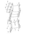
図1は、本実施形態の静翼列部の一部を示す斜視図である。図2は、本実施形態の静翼列部の分解斜視図である。
静翼列部1は、ジェットエンジンの圧縮機に搭載されるものであり、当該圧縮機において動翼列部と交互に空気の流れ方向に複数配列されている。
この静翼列部1は、ジェットエンジンの中心軸を中心として環状に形状設定されており、図1に示すように、インナーバンド2とアウターバンド3との間に静翼4が複数配置された構成を有している。
FIG. 1 is a perspective view showing a part of the stationary blade row portion of the present embodiment. FIG. 2 is an exploded perspective view of the stationary blade row portion of the present embodiment.
The stationary
The stationary
インナーバンド2は、アウターバンド3よりもジェットエンジンの中心軸寄りに配置された環状部材である。
アウターバンド3は、インナーバンド2よりもジェットエンジンの中心軸から半径方向離れた位置に配置される環状部材である。
これらのインナーバンド2とアウターバンド3とに挟まれた領域が空気の流路とされており、当該領域に静翼4が等間隔で複数配置されている。
The
The
A region sandwiched between the
静翼4は、インナーバンド2とアウターバンド3との間において、空気の整流を行うものであり、前縁をジェットエンジンの前方に、後縁をジェットエンジンの後方に向けて配置されている。
The stationary blade 4 performs air rectification between the
図2は、静翼列部1の分解斜視図である。この図に示すように、本実施形態の静翼列部1は、静翼4ごとに個片化されており、この個片化されたユニット(以下、個片化ユニット10と称する)が環状に複数接続されることによって構成されている。
FIG. 2 is an exploded perspective view of the
個片化ユニット10は、連続することによって静翼列部1を形成するものであり、当該静翼列部1の一部を構成するものである。より詳細には、静翼列部1を静翼4ごとに分割し、この分割体の1つが個片化ユニット10とされている。
そして、個片化ユニット10は、図2に示すように、静翼4と、インナーバンド2の一部を構成する個片化インナーバンド11と、アウターバンド3の一部を構成する個片化アウターバンド12とを備えている。
The
As shown in FIG. 2, the
図3は、個片化ユニット10をジェットエンジンの中心軸方向から見た正面図である。
この図に示すように、本実施形態の静翼列部1において各個片化ユニット10は、隣り合う個片化ユニット10と係合する4つのフック部13を有している。
FIG. 3 is a front view of the
As shown in this figure, each
フック部13は、隣の個片化ユニット10のフック部13と係止されることによって隣り合う個片化ユニット10同士を位置決めするものであり、個片化インナーバンド11及び個片化アウターバンド12の端部に設けられている。
より詳細には、隣の個片化インナーバンド11と当接する両方の端部の各々にフック部13が設けられており、一方の端部に設けられたフック部13が上方を向いて突設され、他方の端部に設けられたフック部13が下方を向いて突設されており、フック部は係合部と開口部を備えている。これらのフック部13は、係合部を開口部に差し入れることに
より、フック部13同士が係合した際に相手のフック部13に当接することによって相手のフック部13を拘束する拘束面13a,13bを周方向に2つ備え、一方の拘束面13aが他方の拘束面13bに対して傾斜している。このとき、フック部はその開口側に向かうにつれて幅が大きくなっている形状であればよい。
このようなフック部13同士を係合することによって、周方向に隣り合う個片化ユニット10同士を強固に固定することができる。このため、静翼列部1の剛性が向上し固有振動数の低下を防ぐことができる。
The
More specifically, a
By engaging the
また、このようなフック部13を有する個片化ユニット10は、製造方法として、精密鍛造、粉末射出成型などを用いることで、ネット形状を容易に製造でき、接合コストが不要な上、廃棄される素材余肉も削減される。
Further, the individualized
なお、フック部13は静翼列部1の剛性向上の機能を果たすため、嵌め合いを一定以上にきつくする必要がある。
さらに、この嵌め合いは、製造誤差によるばらつきを考慮しても一定以上の嵌め合いを維持しなければならない。
これを実現するためには、相対するフック部の拘束面13a,13bを、平行でなく、上述のように、一方に対して傾斜をつけた2つの面で構成することが好ましい。
傾斜をつけることで、拘束面13aで2方向の拘束を行え、その分拘束面の数を減らすことができる。拘束面は高精度で製作する必要があるため、拘束面を減らすことは製作コストや製造歩留まりの改善に貢献する。
In addition, since the
Furthermore, this fitting must maintain a certain degree of fitting even when variations due to manufacturing errors are taken into account.
In order to realize this, it is preferable that the constraining
By providing the inclination, the
また、平行な2面を上述の拘束面とした場合には、製造誤差により 嵌め合いが設計意図よりもきつくなった際に、嵌め合いによる干渉に対する逃げ場がなく、組立が困難になるため、きつい嵌め合いが採れない。
一方、本実施形態のように拘束面13aが拘束面13bに対し傾斜している場合には、製造誤差により、嵌め合いが設計意図よりきつくなった際でも、フック部13が干渉を避ける方向に僅かに移動することで干渉が緩和され、組立性が確保できる。これにより一定以上のきつい嵌め合いを採ることが可能である。
また、このときフック部13の僅かな移動に伴ってフック部13の根元に弾性歪が蓄えられる。この弾性歪により、フック部13が元に戻ろうとする反発力が生じるため、拘束面13a,13bにおいて面のはがれが生じず、一定の拘束力が維持され、ひいては剛性向上が達成される。
In addition, when two parallel surfaces are used as the above-mentioned constraining surfaces, when the fit becomes tighter than the design intent due to manufacturing errors, there is no escape from interference due to the fit, and assembly becomes difficult. Cannot fit.
On the other hand, when the constraining
At this time, elastic strain is accumulated at the base of the
このようなブック部13を有する静翼列部1においては、フック壁面(拘束面13a,13b)が径方向に対して角度を持っていることで、径方向、周方向の2方向への変位が制御できる。
また、径方向に関しては、個片化アウターバンド12と個片化インナーバンド11のフック部13を径方向に関して 線対称の形状とすることで 径方向へお互いに突っ張りあい、変位が拘束される。
また、周方向に関しては 各フック部が周方向の嵌合となっており、変位が拘束される。このとき、軸方向に関しては、各個片化ユニットの組み付け後、アウターバンド部3を図示しないケーシングが前後から挟み込むことでアウターバンド部3が固定され、軸方向変位が拘束される。
そして、個片化ユニット10の周方向右端と左端のフック部13を点対称形状とすることで、周方向に周期性を持った形状となり、個片化ユニット10の共通化が可能となる
In the stationary
Further, regarding the radial direction, the
Further, with respect to the circumferential direction, each hook portion is fitted in the circumferential direction, and displacement is restrained. At this time, with respect to the axial direction, after assembling each individual unit, the
And by making the
また、本実施形態は固有振動数の向上を目的とし、隣接する部品との位置関係を積極的に拘束する構造である点で特開平1−310104号公報に開示された発明と相違する。
具体的には、本実施形態のフック部13は、周方向、径方向ともに位置関係が拘束される構造となっている。
Further, the present embodiment is different from the invention disclosed in Japanese Patent Laid-Open No. 1-310104 in that it has a structure for positively constraining the positional relationship with adjacent parts for the purpose of improving the natural frequency.
Specifically, the
また、本実施形態は、回転数上昇過程での捻れ変形が不要で、回転体でなくとも使用できる。また、フック部の形状を調整することで、複数方向への拘束が可能であることに特徴がある。 Further, the present embodiment does not require torsional deformation in the process of increasing the rotational speed, and can be used even if it is not a rotating body. In addition, it is characterized in that it can be restrained in a plurality of directions by adjusting the shape of the hook portion.
なお、構造解析を行った結果、表1に示す振動周波数に関するデータから分かるように、本実施形態は、特開平1−310104号公報に開示された発明や、特開2005−256786号公報に開示された発明と比較して、振動モードの消失や振動数が大幅な向上という効果が得られる。
なお、フック部の場所を調整することで 曲げモード、ねじれモードなど、回避が必要なモードに効果的に対応できる。
As can be seen from the data relating to the vibration frequency shown in Table 1 as a result of structural analysis, the present embodiment is disclosed in Japanese Patent Laid-Open No. 1-310104 and Japanese Patent Laid-Open No. 2005-256786. Compared to the invention, the effects of disappearance of the vibration mode and a significant improvement in the frequency can be obtained.
By adjusting the location of the hook part, it is possible to effectively cope with modes that need to be avoided, such as bending mode and torsion mode.

以上、図面を参照しながら本発明の好適な実施形態について説明したが、本発明は上記実施形態に限定されるものではない。上述した実施形態において示した各構成部材の諸形状や組み合わせ等は一例であって、本発明の主旨から逸脱しない範囲において設計要求等に基づき種々変更可能である。
例えば、フック部は開口部側に向かうにつれて幅が広がっていればよく、拘束面が複数あってもよいし、曲面で構成されていてもよい。
As mentioned above, although preferred embodiment of this invention was described referring drawings, this invention is not limited to the said embodiment. Various shapes, combinations, and the like of the constituent members shown in the above-described embodiments are examples, and various modifications can be made based on design requirements and the like without departing from the gist of the present invention.
For example, the hook portion only needs to increase in width toward the opening side, and there may be a plurality of constraining surfaces or a curved surface.
1……静翼列部、2……インナーバンド、3……アウターバンド、4……静翼、10……個片化ユニット、11……個片化インナーバンド、12……個片化アウターバンド、13……フック部、13a,13b……拘束面 1 …… Static blade row portion, 2 …… Inner band, 3 …… Outer band, 4 …… Static blade, 10 …… Divided unit, 11 …… Divided inner band, 12 …… Divided outer Band, 13 ... Hook, 13a, 13b ... Restraint surface
Claims (2)
各個片化ユニットが開口部と係合部からなるフック部を有し、当該フック部同士を係合することによって隣り合う個片化ユニット同士が接続されていることを特徴とする静翼列部。 An individualized unit including an individualized inner band that constitutes a part of the inner band, an outer band that constitutes a part of the outer band, and a stationary blade that is sandwiched between the inner band and the outer band. A stationary blade row portion formed by connecting a plurality of the directions,
Each vane unit has a hook part composed of an opening and an engaging part, and the individual vane unit is connected by engaging the hook parts with each other. .
Priority Applications (1)
| Application Number | Priority Date | Filing Date | Title |
|---|---|---|---|
| JP2011034515A JP2012172575A (en) | 2011-02-21 | 2011-02-21 | Stator vane cascade |
Applications Claiming Priority (1)
| Application Number | Priority Date | Filing Date | Title |
|---|---|---|---|
| JP2011034515A JP2012172575A (en) | 2011-02-21 | 2011-02-21 | Stator vane cascade |
Publications (1)
| Publication Number | Publication Date |
|---|---|
| JP2012172575A true JP2012172575A (en) | 2012-09-10 |
Family
ID=46975712
Family Applications (1)
| Application Number | Title | Priority Date | Filing Date |
|---|---|---|---|
| JP2011034515A Pending JP2012172575A (en) | 2011-02-21 | 2011-02-21 | Stator vane cascade |
Country Status (1)
| Country | Link |
|---|---|
| JP (1) | JP2012172575A (en) |
Cited By (2)
| Publication number | Priority date | Publication date | Assignee | Title |
|---|---|---|---|---|
| US10577953B2 (en) | 2014-07-14 | 2020-03-03 | Ihi Corporation | Turbine stator vane of ceramic matrix composite |
| CN111486129A (en) * | 2020-04-20 | 2020-08-04 | 中国航发湖南动力机械研究所 | Stator rectifier ring structure, compressor and aircraft engine |
Citations (2)
| Publication number | Priority date | Publication date | Assignee | Title |
|---|---|---|---|---|
| GB813144A (en) * | 1955-12-06 | 1959-05-13 | Bbc Brown Boveri & Cie | Improvements in or relating to turbines or compressors |
| GB2139295A (en) * | 1983-05-05 | 1984-11-07 | Tuomo Kaivola | Thermal joint e.g. for a turbine |
-
2011
- 2011-02-21 JP JP2011034515A patent/JP2012172575A/en active Pending
Patent Citations (2)
| Publication number | Priority date | Publication date | Assignee | Title |
|---|---|---|---|---|
| GB813144A (en) * | 1955-12-06 | 1959-05-13 | Bbc Brown Boveri & Cie | Improvements in or relating to turbines or compressors |
| GB2139295A (en) * | 1983-05-05 | 1984-11-07 | Tuomo Kaivola | Thermal joint e.g. for a turbine |
Cited By (2)
| Publication number | Priority date | Publication date | Assignee | Title |
|---|---|---|---|---|
| US10577953B2 (en) | 2014-07-14 | 2020-03-03 | Ihi Corporation | Turbine stator vane of ceramic matrix composite |
| CN111486129A (en) * | 2020-04-20 | 2020-08-04 | 中国航发湖南动力机械研究所 | Stator rectifier ring structure, compressor and aircraft engine |
Similar Documents
| Publication | Publication Date | Title |
|---|---|---|
| CN108457705B (en) | Method and system for joining ceramic matrix composite material member to metal member | |
| JP5551758B2 (en) | Stator assembly, manufacturing method thereof, and damper spring | |
| CN102132011B (en) | Fixed vane assembly for turbine engine with reduced weight, and a turbine engine including at least one such fixed vane assembly | |
| US9347460B2 (en) | Rotary machine | |
| EP2662531A1 (en) | Steam turbine stator blade and steam turbine | |
| JP2017082666A (en) | Supercharger compressor housing and manufacturing method for the same | |
| US9709072B2 (en) | Angular diffuser sector for a turbine engine compressor, with a vibration damper wedge | |
| JP4269723B2 (en) | Turbine nozzle | |
| JP6370984B2 (en) | Variable nozzle mechanism and variable displacement exhaust turbocharger | |
| JP3933130B2 (en) | Turbine blade | |
| US11002140B2 (en) | Guide vane segment | |
| JP2012172575A (en) | Stator vane cascade | |
| JP2015086873A (en) | Bucket assembly for use in turbine engine | |
| CN110520607B (en) | Turbine and turbocharger with same | |
| US10738640B2 (en) | Shroud, blade member, and rotary machine | |
| JP5365411B2 (en) | Nozzle vanes and turbochargers | |
| US10161266B2 (en) | Nozzle and nozzle assembly for gas turbine engine | |
| EP3232075A1 (en) | Spline connection structure and spline shaft | |
| JP5928271B2 (en) | Compressor housing for supercharger and method for manufacturing the same | |
| US10465599B2 (en) | Turbocharger | |
| JP7097505B2 (en) | Nozzle device and exhaust turbocharger | |
| JP2015090134A (en) | Gas turbine blade | |
| JP2005194903A (en) | Compressor stationary blade ring | |
| US8523518B2 (en) | Systems, methods, and apparatus for linking machine stators | |
| CN113227540A (en) | Rotor blade of rotating body and disk |
Legal Events
| Date | Code | Title | Description |
|---|---|---|---|
| A621 | Written request for application examination |
Free format text: JAPANESE INTERMEDIATE CODE: A621 Effective date: 20131219 |
|
| A131 | Notification of reasons for refusal |
Free format text: JAPANESE INTERMEDIATE CODE: A131 Effective date: 20140909 |
|
| A977 | Report on retrieval |
Free format text: JAPANESE INTERMEDIATE CODE: A971007 Effective date: 20140911 |
|
| A02 | Decision of refusal |
Free format text: JAPANESE INTERMEDIATE CODE: A02 Effective date: 20150203 |