JP2012171483A - Vehicle body structure - Google Patents
Vehicle body structure Download PDFInfo
- Publication number
- JP2012171483A JP2012171483A JP2011035044A JP2011035044A JP2012171483A JP 2012171483 A JP2012171483 A JP 2012171483A JP 2011035044 A JP2011035044 A JP 2011035044A JP 2011035044 A JP2011035044 A JP 2011035044A JP 2012171483 A JP2012171483 A JP 2012171483A
- Authority
- JP
- Japan
- Prior art keywords
- vehicle
- axis
- vehicle body
- cross
- end portion
- Prior art date
- Legal status (The legal status is an assumption and is not a legal conclusion. Google has not performed a legal analysis and makes no representation as to the accuracy of the status listed.)
- Granted
Links
Images


Landscapes
- Body Structure For Vehicles (AREA)
Abstract
Description
本発明は、車体構造に関する。 The present invention relates to a vehicle body structure.
特許文献1には、ヘッドガードを支持するフロントピラーが後方に向かって傾斜する状態に設けられた産業車両において、両フロントピラーが前方に凸に湾曲する形状に形成され、また、外側に位置する面が湾曲面、内側に位置する面が平面となる非対称な断面形状の柱材で形成されている産業車両が記載されている(特許文献1を参照)。 In Patent Document 1, in an industrial vehicle in which a front pillar that supports a head guard is inclined in a rearward direction, both front pillars are formed in a shape that curves convexly forward and are located outside. An industrial vehicle is described that is formed of a pillar material having an asymmetrical cross-sectional shape in which a surface is a curved surface and a surface located inside is a flat surface (see Patent Document 1).
このようなフロントピラーでは、モーメントの方向の断面を大きくすることで、強度が確保される。しかし、部位によってモーメントの方向が異なる場合、全ての部位の強度を確保しようとすると、一様に大きな断面が必要となり、その結果、フロントピラーの質量が増加することになる。 In such a front pillar, the strength is ensured by increasing the cross section in the direction of the moment. However, when the direction of the moment differs depending on the part, to ensure the strength of all the parts, a uniformly large cross section is required, and as a result, the mass of the front pillar increases.
本発明は、上記を考慮し、質量が増加するのを抑制しつつ、部位によって異なるモーメントの方向に対応した強度を確保することができる車体骨格部材を提供することが目的である。 In view of the above, an object of the present invention is to provide a vehicle body skeleton member capable of ensuring strength corresponding to the direction of moment that varies depending on a part while suppressing an increase in mass.
請求項1の車体構造は、車両前後方向に沿って配置されると共に車両前後方向の前端部から中央部に向かうに従って上側に凸状になるように湾曲され、更に断面主軸の強軸が前記前端部では車両前後方向に沿って配置され前記中央部では車両幅方向に沿って配置された車体骨格部材が、車両の両側部側に配置されたている。 The vehicle body structure according to claim 1 is arranged along the vehicle front-rear direction and is curved so as to protrude upward from the front end portion in the vehicle front-rear direction toward the center portion, and the strong axis of the cross-sectional main axis is the front end The vehicle body skeleton members arranged along the vehicle longitudinal direction at the portion and arranged along the vehicle width direction at the central portion are arranged on both sides of the vehicle.
請求項1の車体構造では、前端部では車両前後方向に沿って配置された断面主軸の強軸が、中央部では車両幅方向に沿って配置されている。前面衝突時は車体骨格部材の前端部に作用する車両幅方向の軸心回りのモーメントで強度が決定されるので、車体骨格部材の前端部の強軸を車両前後方向とすることで強度が確保される。側面衝突時は車体骨格部材の中央部に作用する車両前後方向の軸心回りのモーメントで強度が決定されるので、車体骨格部材の中央部の強軸を車両前後方向とすることで強度が確保される。
よって、車体骨格部材の質量が増加するのを抑制しつつ、車両前後方向の前端部と中央部とで異なるモーメントの方向に対応した強度が確保される。
In the vehicle body structure according to the first aspect, the strong axis of the cross-sectional main shaft disposed along the vehicle front-rear direction at the front end portion is disposed along the vehicle width direction at the center portion. In the case of a frontal collision, the strength is determined by the moment around the axis in the vehicle width direction that acts on the front end of the vehicle body frame member. Therefore, the strength is ensured by setting the strong axis at the front end of the vehicle body frame member as the vehicle longitudinal direction. Is done. In the case of a side collision, the strength is determined by the moment about the vehicle longitudinal axis acting on the center part of the vehicle body frame member, so the strength is ensured by setting the strong axis at the center part of the vehicle body frame member to the vehicle longitudinal direction. Is done.
Therefore, strength corresponding to the directions of moments different between the front end portion and the central portion in the vehicle front-rear direction is ensured while suppressing an increase in the mass of the vehicle body skeleton member.
請求項2の車体構造は、前記車体骨格部材は、前記前端部から前記中央部に向かうに従って軸心回りに捩じられて構成されている。 The vehicle body structure according to claim 2 is configured such that the vehicle body skeleton member is twisted about the axis from the front end portion toward the center portion.
請求項2の車体構造では、車体骨格部材を前端部から中央部に向かうに従って軸心回りに捩じられることで、断面主軸の強軸を回転させて前端部と後端部とで強軸の向きを容易に変えている。 In the vehicle body structure according to claim 2, the vehicle body skeleton member is twisted about the axis as it goes from the front end portion toward the center portion, so that the strong axis of the cross-sectional main shaft is rotated, and the strong shaft is The direction is easily changed.
請求項3の車体構造は、前記車体骨格部材は、運転者の視界の高さ近傍では、前記視線と前記強軸とが一致又は略一致するように構成されている。 The vehicle body structure according to claim 3 is configured so that the line of sight and the strong axis coincide or substantially coincide with each other in the vicinity of the height of the driver's field of view.
請求項3の車体構造では、運転者の視界の高さ近傍では、車体骨格部材の強軸が視線と一致又は略一致するように構成されている。よって、車体骨格部材によって遮られる視界の領域が小さくなる。 The vehicle body structure according to claim 3 is configured so that the strong axis of the vehicle body skeleton member coincides with or substantially coincides with the line of sight in the vicinity of the height of the driver's field of view. Therefore, the field of view blocked by the vehicle body skeleton member is reduced.
請求項4の車体構造は、前記車体骨格部材は、前記前端部から前記中央部にかけて一様断面で構成されている。 In the vehicle body structure according to a fourth aspect, the vehicle body skeleton member has a uniform cross section from the front end portion to the central portion.
請求項4の車体構造では、車体骨格部材は前端部から中央部にかけて一様断面で構成されているので、質量の増加が確実に抑えられる。 In the vehicle body structure according to the fourth aspect, since the vehicle body skeleton member has a uniform cross section from the front end portion to the center portion, an increase in mass is reliably suppressed.
請求項1に記載の発明によれば、本発明が適用されていない構造と比較し、車体骨格部材の質量が増加するのを抑制しつつ、車両前後方向の前端部と中央部とで異なるモーメントの方向に対応した強度を確保することができる。 According to the first aspect of the present invention, as compared with the structure to which the present invention is not applied, the moment that is different between the front end portion and the center portion in the vehicle front-rear direction while suppressing an increase in the mass of the vehicle body skeleton member. The strength corresponding to the direction can be ensured.
請求項2に記載の発明によれば、車体骨格部材の断面主軸の強軸を前端部と後端部とで強軸の向きを容易に変えることができる。 According to the second aspect of the present invention, the direction of the strong axis of the main axis of the cross section of the vehicle body skeleton member can be easily changed between the front end portion and the rear end portion.
請求項3に記載の発明によれば、車体骨格部材の強軸が視線と一致していない構造と比較し、車体骨格部材によって遮られる視界の領域を小さくすることができる。 According to the third aspect of the present invention, as compared with a structure in which the strong axis of the vehicle body skeleton member does not coincide with the line of sight, the field of view blocked by the vehicle body skeleton member can be reduced.
請求項4に記載の発明によれば、車体骨格部材が一様断面でない構造と比較し、質量の増加が確実に抑えることができる。 According to the fourth aspect of the present invention, an increase in mass can be reliably suppressed as compared with a structure in which the vehicle body skeleton member does not have a uniform cross section.
図1〜図5を用いて、本発明の実施形態に係る車体骨格部材について説明する。なお、車両前後方向前方側を矢印FRで示し、車両幅方向外側を矢印OUTで示し、車両上下方向上側を矢印UPで示す。また、車両前方側に向かって車両幅方向左側の部材には符号の後にLを付し、車両前方側に向かって車両幅方向右側の部材には符号の後にRを付す。しかし、左右を区別して説明する必要が無い等の場合は、L及びRを省略する。 A vehicle body skeleton member according to an embodiment of the present invention will be described with reference to FIGS. The front side in the vehicle front-rear direction is indicated by an arrow FR, the outer side in the vehicle width direction is indicated by an arrow OUT, and the upper side in the vehicle vertical direction is indicated by an arrow UP. Further, a member on the left side in the vehicle width direction toward the vehicle front side is denoted by L after the reference numeral, and a member on the right side in the vehicle width direction toward the vehicle front side is denoted by R after the reference numeral. However, when there is no need to distinguish between left and right, L and R are omitted.
<全体構成>
まず、本発明の本実施形態に係る車体骨格部材を備える車両10の全体構成について説明する。
<Overall configuration>
First, the overall configuration of the
図1と図2とに示すように、車両10は、一人又は二人乗り(本実施形態では一例として一人乗りとされている)の小型(軽量ボデー構造)のコミュータとされている。車両10を構成する車体フレーム100は、車両幅方向の左右の側部に車両前後方向に沿って配置されたサイドフレーム110L,110Rと、車体骨格部材の一例としてのサイドフレーム200L,200Rとを有している。
As shown in FIG. 1 and FIG. 2, the
サイドフレーム110L,110Rは、車両底部に配置されている。一方、サイドフレーム200L,200Rは、サイドフレーム110L,110Rの上側に配置され、半円形に湾曲した形状とされている。また、サイドフレーム200の前端部202はサイドフレーム110の前端部112付近に接合され、サイドフレーム200の後端部204はサイドフレーム110の後端部114に接合されている。なお、上側のサイドフレーム200についての詳細は後述する。
The
下側のサイドフレーム110L,110Rと上側のサイドフレーム200L,200Rとの間は、車両前後方向の略中央部に車両上下方向に沿って配置されたセンターフレーム120L,120Rで接合されている。
The
上側の左右のサイドフレーム200L,200Rにおけるセンターフレーム120の上部122が接合された中央部206L,206R間には、車両幅方向に沿って配置されたクロスフレーム130(図2参照)が接合されている。また、下側の左右のサイドフレーム110L,110Rにおけるセンターフレーム120L,120Rの下部124L,124Rが接合された中央部116L,116R間には、車両幅方向に沿って配置されたクロスフレーム140(図2参照)が接合されている。
A cross frame 130 (see FIG. 2) arranged along the vehicle width direction is joined between the
また、下側のサイドフレーム110の後端部114とサイドフレーム200の後端部204とが接合された部位間には、車両幅方向に沿って配置されたクロスフレーム150が接合されている。更にサイドフレーム110L,110Rの車両前後方向の前端部112L,112R間に、車両幅方向に沿って配置されたバンパリインフォース160が接合されている。
Further, a
図1に示すように、このような車体フレーム100で囲まれた空間が、運転者20が運転を行うための運転者用空間30となっている。
As shown in FIG. 1, a space surrounded by the
運転者用空間30におけるサイドフレーム110の車両前後方向の中央部の凹部の上側に、運転者20が着座するシート40が設けられている。シート40の前方には、ハンドル42やアクセルペダル(図示略)、ブレーキペダル(図示略)など、運転操作に必要な装置や機構が配置されている。
A
また、本実施形態においては、運転者用空間30の前面にはフロントパネル(図示略)が設けられ、運転者用空間30の上面にはルーフパネル(図示略)が設け、更に後方にはリアパネル(図示略)がそれぞれ設けられている。なお、運転者20が前方と後方とを視認するため、フロントパネルとリアパネルの一部には、透明な樹脂やガラス等で構成されたウインドシールド(図示略)が設けられている。
In the present embodiment, a front panel (not shown) is provided on the front surface of the
本実施形態では、運転者用空間30の両側面は、左右両側のいずれの方向からも運転者20が乗降できるように、開放されている。なお、運転者用空間30の左右両側面に、乗降用のドア等が設けられていてもよい。
In the present embodiment, both side surfaces of the
また、車両10には、動力源(駆動源)(例えば、電気モータやエンジン等)や動力伝達機構などが搭載されている。また、前端部付近と後端付近とには、それぞれ左右一対の前輪16と後輪18とが設けられており、前述の動力源や動力伝達機構によって回転駆動するように構成されている。
The
<サイドフレームの構造の詳細>
つぎに、車体骨格部材の一例としての上側のサイドフレーム200L,200Rの詳細について説明する。
<Details of side frame structure>
Next, details of the upper side frames 200L and 200R as an example of the vehicle body skeleton member will be described.
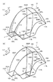
図1と図2とに示され、サイドフレーム200は、サイドフレーム110の上側に配置され、側面視における形状は、上側に凸の略半円状に湾曲した形状とされている。より詳しく説明すると、サイドフレーム200は、前端部202から車両後方側に向かって斜め上方に傾斜したのち、中央部206付近では略水平方向(車両前後方向)に延在し、その後、後端部204(車両後方側)に向かって斜め下方に傾斜している。 As shown in FIGS. 1 and 2, the side frame 200 is arranged on the upper side of the side frame 110, and the shape in the side view is a shape curved in a substantially semicircular shape protruding upward. More specifically, after the side frame 200 is inclined obliquely upward from the front end portion 202 toward the vehicle rear side, the side frame 200 extends in a substantially horizontal direction (vehicle front-rear direction) in the vicinity of the center portion 206, and then the rear end portion. It inclines diagonally downward toward 204 (vehicle rear side).
図3と図4とに示すように、サイドフレーム200は、軸心Gと直交する断面(軸直角断面)が楕円形状の中空のパイプとされている。楕円の長軸が強軸Kとされ、楕円の短軸が弱軸Jとされている。また、楕円の長軸方向の長さを縦幅A1とし、短軸方向の長さを横幅A2とする。 As shown in FIGS. 3 and 4, the side frame 200 is a hollow pipe whose cross section (axial cross section perpendicular to the axis G) is elliptical. The major axis of the ellipse is the strong axis K, and the minor axis of the ellipse is the weak axis J. The length of the ellipse in the major axis direction is defined as a vertical width A1, and the length in the minor axis direction is defined as a lateral width A2.
なお、強軸Kとは軸心Gと直交する断面(軸直角断面)における断面二次モーメントが最大になる断面主軸とされ、弱軸Jとは断面二次モーメントが最小となる断面主軸とされる。また、断面主軸とは、断面の図心を通る直交する二つの軸のうち、その軸に対する断面2次モーメントが最大(強軸)・最小(弱軸)となる組の軸とされる。 Note that the strong axis K is the cross-sectional principal axis that maximizes the cross-sectional secondary moment in the cross-section orthogonal to the axis G (axis-perpendicular cross-section), and the weak axis J is the cross-sectional main axis that minimizes the cross-sectional secondary moment. The In addition, the cross-section main axis is a set of axes having a maximum (strong axis) and minimum (weak axis) cross-sectional secondary moment with respect to the axis among two orthogonal axes passing through the centroid of the cross section.
図3(A)に示すように、左側のサイドフレーム200の前端部202Lは、強軸Kが車両前後方向に沿って配置され、弱軸Jが車両幅方向に沿って配置されている。
As shown in FIG. 3A, in the
図3(B)に示すように、サイドフレーム200Lは、車両後方側に向かうに従って軸心G回りに反時計回りに捩じれ、徐々に強軸Kが回転する。そして、図3(C)に示すように、車両前後方向の中央部206Lでは強軸Kが車両幅方向に沿った配置となり、弱軸Jが車両上下方向に沿った配置となる。
As shown in FIG. 3B, the
更に、車両後方側に向かうに従って軸心G回りに、反時計回りに捩じれ、後端部204L(図1と図2参照)では強軸Kが車両前後方向に沿った配置となり、弱軸Jが車両幅方向に沿った配置となる(図3(A)と同じ配置)。
Furthermore, as it goes to the vehicle rear side, it is twisted counterclockwise around the axis G, and at the
右側のサイドフレーム200Rも同様に、前端部202R(図2参照)は、強軸Kが車両前後方向に沿った配置され、弱軸Jが車両幅方向に沿った配置とされている。そして、車両後方側に向かうに従って軸心G回りに時計回りに捩じれ、徐々に強軸Kが回転し(図4参照)、車両前後方向の中央部206R(図2参照)では強軸Kが車両幅方向に沿った配置となり弱軸Jが車両上下方向に沿った配置となり、更に後端部204R(図2参照)では強軸Kが車両前後方向に沿った配置となり弱軸Jが車両幅方向に沿った配置となる。つまり、図3(B)が左右対称以外は図3と同様の図となる。
Similarly, in the
また、図4に示すように、運転者20の目(視界)24の高さ近傍では、視線Sと強軸Kとが一致又は略一致するように設定されている。
Further, as shown in FIG. 4, the line of sight S and the strong axis K are set so as to coincide or substantially coincide with each other in the vicinity of the height of the eyes (view) 24 of the
このように、本実施形態のサイドフレーム200は、軸心Gと直交する断面(軸直角断面)は一様断面であるが、車両後方側に向かうに従って軸心G回りに捩じれ強軸Kが回転し向きが変化する捩じれ構造のパイプとなっている。また、このような捩じれ構造のサイドフレーム200は、例えば、ハイドロフォーム成形によって成型することができる。 As described above, the side frame 200 of the present embodiment has a uniform cross section perpendicular to the axis G (axial right angle cross section), but twists around the axis G toward the vehicle rear side and the strong axis K rotates. The pipe has a twisted structure whose direction changes. Moreover, the side frame 200 having such a twisted structure can be molded by, for example, hydroforming.
<作用及び効果>
つぎに本実施形態の作用及び効果について説明する。
<Action and effect>
Next, the operation and effect of this embodiment will be described.
ここで図5(A)は、車両10の前面衝突時における車体フレーム100に作用する車両幅方向の軸回りのモーメントの分布を模式的に図示している。また、図5(B)は、車両10の側面衝突時(この図では車両左側への衝突)における車体フレーム100に作用する車両上下方向の軸回りモーメントの分布を模式的に図示している。なお、図示おいて、線Mが長いほどモーメントが大きいことを表している。
Here, FIG. 5A schematically illustrates a distribution of moments about an axis in the vehicle width direction that acts on the
図5(A)に示されているように、車両10の前面衝突時においては、車両前端部のバンパリインフォース160に荷重Fが入力される。よって、サイドフレーム200の前端部202には車両幅方向の軸回りのモーメントが生じる。また、このモーメントは車両後方側に向かうに従って小さくなる。
As shown in FIG. 5A, during a frontal collision of the
図5(B)に示されているように、車両10の側面衝突時においては、車両側部のセンターフレーム120に荷重Fが入力される。よって、サイドフレーム200の中央部206には車両前後方向の軸回りのモーメントが生じる。また、このモーメントは車両前方側及び後方側に向かうに従って小さくなる
As shown in FIG. 5 (B), during a side collision of the
図3と図4とに示すように、本実施形態の車両10のサイドフレーム200は、前端部202は車両前後方向を強軸Kとして配置されている(図3(A)を参照)。サイドフレーム200の前端部202は、車両幅方向の軸回りのモーメントで強度が決定されるので、前端部202の強軸K(断面係数が大きくなる方向)を車両前後方向とすることで強度が確保されている。
As shown in FIGS. 3 and 4, in the side frame 200 of the
サイドフレーム200は、車両後後方側に向かうに従って軸心G回りに捩じれ徐々に強軸Kが回転する。そして、車両前後方向の中央部付近では車両幅方向が強軸Kとなる。サイドフレーム200の中央部206は、車両前後方向の軸回りのモーメントで強度が決定されるので、中央部206の強軸K(断面係数が大きくなる方向)を車両前後方向とすることで強度が確保されている。 The side frame 200 is twisted about the axis G as it goes to the rear rear side of the vehicle, and the strong axis K gradually rotates. The vehicle width direction is the strong axis K in the vicinity of the center in the vehicle front-rear direction. Since the strength of the central portion 206 of the side frame 200 is determined by the moment about the axis in the vehicle longitudinal direction, the strength is obtained by setting the strong axis K (direction in which the section modulus increases) of the central portion 206 as the vehicle longitudinal direction. It is secured.
なお、図示は省略するが、車両10の後前面衝突時においては、前面衝突時と同様にサイドフレーム200の後端部204には、車両前端部のクロスフレーム150に荷重Fが入力され、サイドフレーム200の後端部204には車両幅方向の軸回りのモーメントが生じる。よって、サイドフレーム200の後端部204は、車両幅方向の軸回りのモーメントで強度が決定されるので、後端部204の強軸K(断面係数が大きくなる方向)を車両前後方向とすることで強度が確保されている。
Although illustration is omitted, at the time of rear-front collision of the
このようにサイドフレーム200は、軸心Gと直交する断面は一様断面である(図3、図4を参照)。しかし、サイドフレーム200を車両後方側に向かうに従って軸心G回りに捩じれ強軸Kが回転し向きが変化する捩じれ構造とすることで、サイドフレーム200の質量(軸直角断面の面積や肉厚)が増加するのを抑制しつつ、前端部202及び中央部206、更に後端部204で異なるモーメントの方向に対応した強度を確保することができる。 Thus, the side frame 200 has a uniform cross section perpendicular to the axis G (see FIGS. 3 and 4). However, the side frame 200 is twisted about the axis G toward the rear side of the vehicle and has a twisted structure in which the strong shaft K rotates and changes its direction, so that the mass of the side frame 200 (area and thickness of the cross section perpendicular to the axis). It is possible to ensure the strength corresponding to the directions of different moments at the front end portion 202 and the central portion 206 and further at the rear end portion 204 while suppressing the increase in the pressure.
また、図4に示すように、運転者20の目(視界)24の高さ近傍では(図3も参照)、視線Sと強軸Kとが一致又は略一致するように設定されている。よって、例えば、視線Sと強軸Kとが一致又は略一致してない場合と比較し、運転者20の視界を遮る領域が狭くなる。
Further, as shown in FIG. 4, the line of sight S and the strong axis K are set to coincide with each other or substantially coincide with each other in the vicinity of the height of the eyes (view) 24 of the driver 20 (see also FIG. 3). Therefore, for example, as compared with the case where the line of sight S and the strong axis K do not coincide or substantially coincide with each other, the area that blocks the field of view of the
<変形例>
つぎに本実施形態のサイドフレームの変形例について、図6と図7とを用いて説明する。なお、上記実施形態の上側のサイドフレーム200L,200R(図2参照)が、変形例ではサイドフレーム300L,300Rとされている。また、後述するように、変形例のサイドフレーム300L,300Rは、サイドフレーム200L,200Rと断面形状が異なるだけで、側面視における全体形状等は、サイドフレーム200L,200Rと同様の構成とされている。
<Modification>
Next, a modification of the side frame of the present embodiment will be described with reference to FIGS. In the modification, the upper side frames 200L and 200R (see FIG. 2) in the above embodiment are the side frames 300L and 300R. Further, as will be described later, the modified side frames 300L and 300R differ from the side frames 200L and 200R only in cross-sectional shape, and the overall shape and the like in a side view are the same as those of the side frames 200L and 200R. Yes.
車体骨格部材の一例としてのサイドフレーム300L,300Rは、軸心Gと直交する断面(軸直角断面)が略台形状の中空のパイプとされている。また、台形の高さである縦幅A1は、台形の横幅A2(下底303と略一致)よりも長い。よって、強軸Kは台形の高さ方向と一致し、弱軸Jは、下底303及び上底305に沿った方向と一致する。 The side frames 300L and 300R as an example of the vehicle body skeleton member are hollow pipes having a substantially trapezoidal cross section perpendicular to the axis G (a cross section perpendicular to the axis). Further, the vertical width A1 which is the height of the trapezoid is longer than the horizontal width A2 of the trapezoid (substantially coincides with the lower base 303). Therefore, the strong axis K coincides with the height direction of the trapezoid, and the weak axis J coincides with the direction along the lower base 303 and the upper base 305.
図6(A)に示すように、左側のサイドフレーム300Lの前端部302Lでは、下底303L側が車両前方側を向き、強軸Kは車両前後方向とされ弱軸Jは車両幅方向とされている。図6(B)に示すように、サイドフレーム300Lは、車両後方側に向かうに従って、軸心G回りに反時計回りに捩じれ、徐々に強軸Kが回転する。
As shown in FIG. 6A, in the front end portion 302L of the
そして、図6(C)に示すように、車両前後方向の中央部306Lでは、下底303L側が車両幅方向左外側を向き強軸Kは車両幅方向となり弱軸Jは車両上下方向となる。更に、車両後方側に向かうに従って軸心G回りに反時計回りに捩じれ、後端部では下底303側が車両後方側を向き、強軸Kは車両前後方向となり弱軸Jは車両幅方向となる(図6(A)と上下逆方向となった配置)。
As shown in FIG. 6C, in the
右側のサイドフレーム300R(図7参照)も同様に前端部では、下底303側が車両前方側を向き、強軸Kは車両前後方向とされ弱軸Jは車両幅方向とされている。そして、車両後方側に向かうに従って軸心G回りに時計回りに捩じれ、徐々に強軸Kが回転し(図4参照)、車両前後方向の中央部では下底303側が車両幅方向右外側に向き強軸Kは車両幅方向となり弱軸Jは車両上下方向となる(図6(B)が左右対称以外は図6と同様の図となる)。更に、車両後方側に向かうに従って軸心G回りに時計回りに捩じれ、後端部では下底303側が車両後方側を向き、強軸Kは車両前後方向となり弱軸Jは車両幅方向となる。
Similarly, in the
また、図7に示すように、運転者20の目(視界)24の高さ近傍では、視線Sと強軸Kとが一致又は略一致するように設定されている。また、台形の下底303側が外側(運転者20から遠い側)に向いた配置とされている。
Further, as shown in FIG. 7, the line of sight S and the strong axis K are set so as to coincide or substantially coincide with each other in the vicinity of the height of the eye (view) 24 of the
なお、このように、サイドフレーム300は、軸心Gと直交する断面は一様断面であるが、車両後方側に向かうに従って軸心G回りに捩じれ、強軸Kが回転し向きが変化する捩じれ構造のパイプとなっている。また、このような捩じれ構造のサイドフレーム300も同様に、ハイドロフォーム成形等によって成型することができる。 As described above, the side frame 300 has a uniform cross section perpendicular to the axis G. However, the side frame 300 is twisted around the axis G toward the rear side of the vehicle, and the strong axis K rotates to change the direction. It is a pipe of structure. Similarly, the side frame 300 having such a twisted structure can be formed by hydroforming or the like.
<作用及び効果>
つぎに変形例のサイドフレーム300の作用及び効果について説明する。
<Action and effect>
Next, operations and effects of the modified side frame 300 will be described.
サイドフレーム300は、軸心Gと直交する断面(軸直角断面)は一様断面である(図6、図7を参照)。しかし、サイドフレーム300を、車両後方側に向かうに従って軸回りに捩じれ強軸Kが回転し向きが変化する捩じれ構造とすることで、サイドフレーム300の質量(軸直角断面の面積や肉厚)が増加するのを抑制しつつ、前端部302及び中央部306、更に後端部で異なるモーメントの方向に対応した強度を確保することができる。 The side frame 300 has a uniform cross section (cross section perpendicular to the axis) perpendicular to the axis G (see FIGS. 6 and 7). However, the side frame 300 has a torsional structure in which the strong axis K rotates and the direction changes as the vehicle moves toward the rear of the vehicle, so that the mass of the side frame 300 (area and thickness of the cross section perpendicular to the axis) is increased. While suppressing the increase, it is possible to secure the strength corresponding to the directions of moments different at the front end portion 302 and the central portion 306 and further at the rear end portion.
また、図7に示すように、運転者20の目(視界)24の高さ近傍では(図3も参照)、視線Sと強軸Kとが一致又は略一致するように設定されている。そして、このとき、運転者20の視界を遮る最大幅が横幅A2(下底303)となるように、上底305の幅が設定されている。このように視線を遮る弱軸J方向の横幅A2が運転者20から遠くなる位置となるようにするとで、例えば、下底303が手前側にある構成と比較し、運転者20の視界を遮る領域が狭くなる。
Further, as shown in FIG. 7, the line of sight S and the strong axis K are set so as to coincide or substantially coincide with each other in the vicinity of the height of the eyes (view) 24 of the driver 20 (see also FIG. 3). At this time, the width of the upper base 305 is set so that the maximum width that blocks the field of view of the
<その他>
尚、本発明は上記実施形態に限定されない。
<Others>
The present invention is not limited to the above embodiment.
例えば、上記実施形態及び変形例では、車体骨格部材の一例としてのサイドフレームは、軸直角断面が略楕円又は略台形状の中空のパイプであったが、これに限定されない。中実の棒状のフレームでもよい。また、軸直角断面が略矩形形状や略三角形状であってもよい。或いは、断面H形状や断面C形状であってもよい。要は、軸直角断面が強軸と弱軸とを有する一様断面の車体骨格部材であればよい。 For example, in the above embodiment and the modification, the side frame as an example of the vehicle body skeleton member is a hollow pipe having a substantially elliptical or substantially trapezoidal cross section at right angles to the axis, but is not limited thereto. A solid rod-like frame may be used. Further, the cross section perpendicular to the axis may be a substantially rectangular shape or a substantially triangular shape. Alternatively, it may have a cross-sectional H shape or a cross-sectional C shape. In short, any body frame member having a uniform cross section in which the cross section perpendicular to the axis has a strong axis and a weak axis may be used.
また、例えば、上記実施形態及び変形例では、左右のサイドフレームは、クロスフレームを介して連結されていたが、これに限定されない。例えば、サイドフレームの後端や前端を車両幅方向の内側に絞り、端部同士を接合してもよい。 Further, for example, in the above embodiment and the modification, the left and right side frames are connected via the cross frame, but the present invention is not limited to this. For example, the rear end or front end of the side frame may be throttled inward in the vehicle width direction, and the ends may be joined together.
また、例えば、上記実施形態及び変形例では、車両10は、一人又は二人乗り(本実施形態では一人乗り)の小型のコミュータとされていたが、これに限定されない。パーソナルモビリティ、マイクロカー(ミニカー)、ゴルフ用等の乗用カート、屋根付原動機付自転車、軽車両等にも本発明を適用することができる。
Further, for example, in the above-described embodiment and the modification, the
更に、本発明の要旨を逸脱しない範囲において種々なる態様で実施し得ることは言うまでもない。 Furthermore, it cannot be overemphasized that it can implement with a various aspect in the range which does not deviate from the summary of this invention.
10 車両
100 車体フレーム
200L サイドフレーム(車体骨格部材)
200R サイドフレーム(車体骨格部材)
202L 前端部
202R 前端部
204L 後端部
204R 後端部
206L 中央部
206R 中央部
300L サイドフレーム(車体骨格部材)
300R サイドフレーム(車体骨格部材)
302L 前端部
306L 中央部
G 軸心
K 強軸
J 弱軸
10
200R Side frame (body skeleton member)
202L
300R side frame (body frame)
302L
G axis
K strong axis
J Weak axis
Claims (4)
Priority Applications (1)
| Application Number | Priority Date | Filing Date | Title |
|---|---|---|---|
| JP2011035044A JP5601241B2 (en) | 2011-02-21 | 2011-02-21 | Body structure |
Applications Claiming Priority (1)
| Application Number | Priority Date | Filing Date | Title |
|---|---|---|---|
| JP2011035044A JP5601241B2 (en) | 2011-02-21 | 2011-02-21 | Body structure |
Publications (2)
| Publication Number | Publication Date |
|---|---|
| JP2012171483A true JP2012171483A (en) | 2012-09-10 |
| JP5601241B2 JP5601241B2 (en) | 2014-10-08 |
Family
ID=46974771
Family Applications (1)
| Application Number | Title | Priority Date | Filing Date |
|---|---|---|---|
| JP2011035044A Expired - Fee Related JP5601241B2 (en) | 2011-02-21 | 2011-02-21 | Body structure |
Country Status (1)
| Country | Link |
|---|---|
| JP (1) | JP5601241B2 (en) |
Citations (4)
| Publication number | Priority date | Publication date | Assignee | Title |
|---|---|---|---|---|
| JPH10109662A (en) * | 1996-10-04 | 1998-04-28 | Mitsubishi Motors Corp | Body structure for automobile |
| JPH11348701A (en) * | 1998-06-05 | 1999-12-21 | Toyota Autom Loom Works Ltd | Structural material for industrial vehicle and the industrial vehicle |
| JP2000219155A (en) * | 1999-01-29 | 2000-08-08 | Mazda Motor Corp | Body structure of vehicle |
| JP2007063839A (en) * | 2005-08-31 | 2007-03-15 | Kobelco Contstruction Machinery Ltd | Protection structure for construction equipment, and cab for construction equipment |
-
2011
- 2011-02-21 JP JP2011035044A patent/JP5601241B2/en not_active Expired - Fee Related
Patent Citations (4)
| Publication number | Priority date | Publication date | Assignee | Title |
|---|---|---|---|---|
| JPH10109662A (en) * | 1996-10-04 | 1998-04-28 | Mitsubishi Motors Corp | Body structure for automobile |
| JPH11348701A (en) * | 1998-06-05 | 1999-12-21 | Toyota Autom Loom Works Ltd | Structural material for industrial vehicle and the industrial vehicle |
| JP2000219155A (en) * | 1999-01-29 | 2000-08-08 | Mazda Motor Corp | Body structure of vehicle |
| JP2007063839A (en) * | 2005-08-31 | 2007-03-15 | Kobelco Contstruction Machinery Ltd | Protection structure for construction equipment, and cab for construction equipment |
Also Published As
| Publication number | Publication date |
|---|---|
| JP5601241B2 (en) | 2014-10-08 |
Similar Documents
| Publication | Publication Date | Title |
|---|---|---|
| JP6798457B2 (en) | Vampari Information | |
| CN201626483U (en) | Automobile front floor assembly | |
| CN106005015B (en) | A kind of pure electric vehicle body frame structure for automotive | |
| JP2004142584A (en) | Body rear portion structure of automobile | |
| US20140049073A1 (en) | Front body structure | |
| CN103429487B (en) | Front vehicle body structure | |
| JP2017024698A (en) | Vehicle body coupling structure | |
| ITUB20153952A1 (en) | VEHICLE | |
| JP6519003B2 (en) | Mounting structure of trailing arm | |
| US9505283B2 (en) | Independent suspension system of drive wheel | |
| JP5601241B2 (en) | Body structure | |
| JP6068669B2 (en) | Body front structure | |
| JPWO2018051789A1 (en) | Body frame of a motorcycle | |
| JP6020932B2 (en) | Auto body structure | |
| KR20200134493A (en) | Front vehicle body reinforcing structure | |
| JP2011240762A (en) | Vehicle front structure | |
| JP7172884B2 (en) | vehicle frame | |
| JP2005170176A (en) | Vehicle body reinforcement structure for vehicle | |
| JP2014162468A (en) | Vehicle body structure of automobile | |
| KR101492008B1 (en) | Roof structure of vehicle | |
| KR20120126906A (en) | Connecting structure of vehicle front body | |
| US20230331183A1 (en) | Work Vehicle | |
| JP2022128972A (en) | Vehicular body side member structure | |
| JP5505287B2 (en) | Rear body structure | |
| JP6868947B2 (en) | Vehicle structure |
Legal Events
| Date | Code | Title | Description |
|---|---|---|---|
| A621 | Written request for application examination |
Free format text: JAPANESE INTERMEDIATE CODE: A621 Effective date: 20131017 |
|
| A977 | Report on retrieval |
Free format text: JAPANESE INTERMEDIATE CODE: A971007 Effective date: 20140709 |
|
| TRDD | Decision of grant or rejection written | ||
| A01 | Written decision to grant a patent or to grant a registration (utility model) |
Free format text: JAPANESE INTERMEDIATE CODE: A01 Effective date: 20140722 |
|
| A61 | First payment of annual fees (during grant procedure) |
Free format text: JAPANESE INTERMEDIATE CODE: A61 Effective date: 20140804 |
|
| R151 | Written notification of patent or utility model registration |
Ref document number: 5601241 Country of ref document: JP Free format text: JAPANESE INTERMEDIATE CODE: R151 |
|
| LAPS | Cancellation because of no payment of annual fees |