JP2012170837A - Atomizer and unmanned helicopter - Google Patents
Atomizer and unmanned helicopter Download PDFInfo
- Publication number
- JP2012170837A JP2012170837A JP2011032330A JP2011032330A JP2012170837A JP 2012170837 A JP2012170837 A JP 2012170837A JP 2011032330 A JP2011032330 A JP 2011032330A JP 2011032330 A JP2011032330 A JP 2011032330A JP 2012170837 A JP2012170837 A JP 2012170837A
- Authority
- JP
- Japan
- Prior art keywords
- disk
- atomizer
- outer peripheral
- disks
- chemical
- Prior art date
- Legal status (The legal status is an assumption and is not a legal conclusion. Google has not performed a legal analysis and makes no representation as to the accuracy of the status listed.)
- Granted
Links
- AZEXKNLEPCBDHH-UHFFFAOYSA-N C1C2C=C=CC12 Chemical compound C1C2C=C=CC12 AZEXKNLEPCBDHH-UHFFFAOYSA-N 0.000 description 1
Images


Classifications
-
- B—PERFORMING OPERATIONS; TRANSPORTING
- B05—SPRAYING OR ATOMISING IN GENERAL; APPLYING FLUENT MATERIALS TO SURFACES, IN GENERAL
- B05B—SPRAYING APPARATUS; ATOMISING APPARATUS; NOZZLES
- B05B3/00—Spraying or sprinkling apparatus with moving outlet elements or moving deflecting elements
- B05B3/02—Spraying or sprinkling apparatus with moving outlet elements or moving deflecting elements with rotating elements
- B05B3/10—Spraying or sprinkling apparatus with moving outlet elements or moving deflecting elements with rotating elements discharging over substantially the whole periphery of the rotating member, i.e. the spraying being effected by centrifugal forces
- B05B3/1007—Spraying or sprinkling apparatus with moving outlet elements or moving deflecting elements with rotating elements discharging over substantially the whole periphery of the rotating member, i.e. the spraying being effected by centrifugal forces characterised by the rotating member
- B05B3/1021—Spraying or sprinkling apparatus with moving outlet elements or moving deflecting elements with rotating elements discharging over substantially the whole periphery of the rotating member, i.e. the spraying being effected by centrifugal forces characterised by the rotating member with individual passages at its periphery
Abstract
Description
本発明は、液体状の薬液を散布するアトマイザー、および、前記アトマイザーを備える無人ヘリコプタの技術に関する。 The present invention relates to an atomizer for spraying a liquid chemical and an unmanned helicopter technology including the atomizer.
従来、飛行中の無人ヘリコプタから圃場に向けて液体状の薬液を空中に散布する薬液散布装置には、ノズル式やアトマイザー式のものがある。アトマイザー式の散布装置(以下アトマイザーと称する)は、複数枚のドーナツ状の円盤が円盤の間に隙間が形成されるように重ねて配置される構成となっている(特許文献1参照)。
また、アトマイザーの円盤は、その外周端に複数個の突起を有する。
そして、アトマイザーでは、円盤が回転することによって、遠心力によって前記円盤間の隙間に流入させた薬液は、円盤の外周端から放出される。このとき、前記薬液は、円盤の外周端における各突起の先端部から放出されることにより、その粒経を小さくなり霧化される。
以上のようにしてアトマイザーでは、薬液が噴霧されるようになっている。
2. Description of the Related Art Conventionally, there are nozzle type and atomizer type chemical liquid spraying apparatuses that spray a liquid chemical liquid in the air from an unmanned helicopter in flight toward a farm field. An atomizer-type spraying device (hereinafter referred to as an atomizer) has a configuration in which a plurality of donut-shaped disks are arranged so as to form a gap between the disks (see Patent Document 1).
The atomizer disk has a plurality of protrusions on its outer peripheral edge.
In the atomizer, when the disk rotates, the chemical liquid that has flowed into the gap between the disks by centrifugal force is discharged from the outer peripheral end of the disk. At this time, the chemical solution is discharged from the tip of each protrusion at the outer peripheral end of the disk, thereby reducing the particle size and atomizing.
As described above, in the atomizer, the chemical solution is sprayed.
しかしながら、従来におけるアトマイザーでは、円盤における外周端に薬液が均一にいきわたらず、円盤における各突起によってその先端部に至った薬液の量に大きな差異が生じる場合がある。
そして、円盤における各突起への薬液の流量の差異が大きいと、円盤の外側に放出される薬液の粒経の大きさについても差異が大きくなる。薬液の粒経の大きさについての差異が大きいと、円盤の外側に放出されて散布される薬液の中には、メインロータの気流によって不必要に広範囲に流されたりするものや、一定の範囲において集中的に散布されるもの等が生じる。
このように従来におけるアトマイザーでは、円盤における外周端に薬液が均一にいきわたらず、円盤の外側に放出される薬液の粒経の大きさについての差異が大きいために、薬液を所望の位置に均一に散布することができない、という問題があった。
However, in the conventional atomizer, the chemical solution does not spread uniformly at the outer peripheral end of the disk, and there may be a large difference in the amount of the chemical solution that reaches the tip portion due to each protrusion in the disc.
And if the difference of the flow volume of the chemical | medical solution to each processus | protrusion in a disk is large, a difference will also become large also about the magnitude | size of the particle size of the chemical | medical solution discharged | emitted on the outer side of a disk. If there is a large difference in the size of the particle size of the chemical solution, some of the chemical solution that is discharged to the outside of the disk and sprayed may be unnecessarily widened by the air flow of the main rotor, or a certain range In such a case, there are things that are intensively sprayed.
As described above, in the conventional atomizer, the chemical solution does not spread uniformly at the outer peripheral edge of the disk, and the difference in the size of the particle size of the chemical solution released to the outside of the disk is large. There was a problem that it could not be sprayed.
本発明は以上の如き状況に鑑みてなされたものであり、円盤における外周端に薬液をより均一にいきわたらせて、円盤の外側に放出される薬液の粒経の大きさをより均一にし、所望の位置に薬液をより均一に散布することができるアトマイザーを提供することを課題とする。 The present invention has been made in view of the situation as described above, and more uniformly distributes the chemical liquid to the outer peripheral end of the disk, makes the particle size of the chemical liquid released to the outside of the disk more uniform, desired It is an object of the present invention to provide an atomizer capable of more uniformly spraying a chemical solution at the position.
本発明の解決しようとする課題は以上の如くであり、次にこの課題を解決するための手段を説明する。 The problem to be solved by the present invention is as described above. Next, means for solving the problem will be described.
即ち、請求項1においては、複数枚のドーナツ状の円盤が、前記円盤間にそれぞれ隙間が形成されるように重ねて配置され、前記円盤が回転することによって、遠心力によって前記円盤間の隙間に流入させた薬液を前記円盤の外周端から放出して散布を行う、アトマイザーであって、前記円盤は、前記円盤の外周端に複数個の突起を有し、前記円盤の上面または下面に前記円盤の中心側から前記円盤の外周端側に向かって前記突起の先端に至るように形成される案内溝を複数有するものである。 That is, in claim 1, a plurality of donut-shaped disks are arranged so as to form gaps between the disks, and the gaps between the disks are caused by centrifugal force by rotating the disks. An atomizer that discharges and discharges the chemical liquid that has flowed into the disk from the outer peripheral end of the disk, the disk having a plurality of protrusions at the outer peripheral end of the disk, and the upper surface or the lower surface of the disk A plurality of guide grooves formed so as to reach the tip of the protrusion from the center side of the disk toward the outer peripheral end side of the disk.
請求項2においては、前記円盤間の隙間は、内周側と外周側とで異なる間隔となるように形成されるものである。 According to a second aspect of the present invention, the gaps between the disks are formed to have different intervals on the inner peripheral side and the outer peripheral side.
請求項3においては、前記複数の円盤の上方に配置されるとともに、前記円盤の中央に形成される中央孔より外側であって前記円盤における外周端より内側に外側端が位置するように配置される、飛散防止カバーを有するものである。
In
請求項4においては、請求項1から請求項3のいずれか一項に記載のアトマイザーを備える、無人ヘリコプタとするものである。 In Claim 4, it is set as an unmanned helicopter provided with the atomizer as described in any one of Claims 1-3.
本発明の効果として、以下に示すような効果を奏する。 As effects of the present invention, the following effects can be obtained.
即ち、本発明によれば、円盤における外周端に薬液をより均一にいきわたらせて、円盤の外側に放出される薬液の粒経の大きさをより均一にして、所望の位置に薬液をより均一に散布することができる。 That is, according to the present invention, the chemical solution is distributed more uniformly on the outer peripheral edge of the disc, the size of the particle size of the chemical solution released to the outside of the disc is made more uniform, and the chemical solution is more uniformly distributed at a desired position. Can be sprayed on.
請求項2に係る発明によれば、例えば、内周側の間隔が外周側の間隔よりも狭く構成すると、円盤間の隙間に薬液が流入する流量を制限し、流入した薬液を、スムーズに円盤の外周端に至らせて、薬液をより均一にいきわたらせることができる。逆に、外周側の間隔が内周側の間隔よりも狭く構成すると、外周側においてより高い圧力を受けて外周端から外側に薬液が放出されることとなって、薬液の粒経を小さくすることができる。
したがって、円盤における外周端に薬液をより均一にいきわたらせて、円盤の外側に方放出される薬液の粒経の大きさをより均一にして、所望の位置に薬液をより均一に散布することができる。
According to the second aspect of the present invention, for example, when the inner circumferential side interval is configured to be narrower than the outer circumferential side interval, the flow rate of the chemical liquid flowing into the gap between the disks is limited, and the flowing chemical liquid is smoothly It is possible to spread the chemical liquid more uniformly by reaching the outer peripheral edge of. On the contrary, if the outer peripheral side interval is configured to be narrower than the inner peripheral side interval, the drug solution is discharged from the outer peripheral end by receiving a higher pressure on the outer peripheral side, thereby reducing the particle size of the chemical solution. be able to.
Therefore, it is possible to spread the chemical liquid more uniformly on the outer peripheral edge of the disk, to make the size of the particle size of the chemical liquid released toward the outside of the disk more uniform, and to distribute the chemical liquid more uniformly at a desired position. it can.
請求項3に係る発明によれば、簡易構造で、飛散防止カバーの外面または内面に付着した薬液が集まってアトマイザーの外に滴り落ちることを防止して、確実に薬液を噴霧することができる。
According to the invention which concerns on
請求項4に係る発明によれば、アトマイザーの円盤における外周端に薬液をより均一にいきわたらせて、円盤の外側に放出される薬液の粒経の大きさをより均一にして、所望の位置に薬液をより均一に散布することができる。 According to the invention of claim 4, the chemical solution is more uniformly distributed on the outer peripheral end of the disk of the atomizer, the size of the particle size of the chemical solution released to the outside of the disk is made more uniform, and the desired position is obtained. The chemical solution can be more uniformly sprayed.
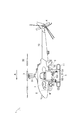
次に、本発明の実施形態に係るアトマイザー60について図1から図9を用いて説明する。なお、以下の説明では、図1に示す矢印Aの方向を、アトマイザー60が装着される無人ヘリコプタ1の前方として定義する。
Next, an
まず、無人ヘリコプタ1の全体構成について説明する。
無人ヘリコプタ1は、遠隔操縦によって飛行して薬液を圃場に散布するものであり、図1または図2に示すように、メインロータ3と、テールロータ4と、薬液散布装置5と、エンジン7と、機体フレーム9等を具備する。
First, the overall configuration of the unmanned helicopter 1 will be described.
The unmanned helicopter 1 flies by remote control and sprays the chemical liquid on the field. As shown in FIG. 1 or 2, the
無人ヘリコプタ1では、機体フレーム9上にエンジン7と薬液散布装置5のポンプ等が載置され、エンジン7やポンプ等はカバー8により覆われ、機体フレーム9の下部にスキッド11が固定される。スキッド11は左右両側下方に突設して、機体を支えるものである。エンジン7の出力軸には、回転軸31やポンプが連動連結される。
回転軸31は、機体フレーム9から機体上方に突出するように構成される。回転軸31には、機体の上部においてメインロータ3とスタビライザ32が固定される。メインロータ3は、無人ヘリコプタ1の機体の上部に設けられ、機体フレーム9に搭載されたエンジン7により回転駆動可能とされる。メインロータ3は、その回転駆動により機体に与えられる揚力を変化させて機体を空中に浮揚させ、機体を上昇または下降させる。メインロータ3は、その回転速度、およびメインロータ3の翼面とメインロータ3の回転軸31とが成す傾きを変更することができる。メインロータ3は、回転軸31を機体の前後方向または左右方向に傾けることにより、機体に前後方向または左右方向に移動するための力を付与する。
In the unmanned helicopter 1, the engine 7 and the pump of the chemical solution spraying device 5 are mounted on the body frame 9, the engine 7 and the pump are covered with the cover 8, and the
The rotating
テールロータ4は、機体の後部に突設されたビーム10の後部に設けられ、エンジン7により回転駆動可能とされる。テールロータ4は、メインロータ3の回転により機体に作用する反動トルク(機体をメインロータ3が回転する方向の逆方向に回転させようとする力)を打ち消す力の大きさを変化させて、機体を右旋回または左旋回させる、あるいは機首の方向を略一定の方向に保持させる。テールロータ4は、その回転速度、およびテールロータ4の翼面とテールロータ4の回転軸とが成す傾きを変更することができる。
The tail rotor 4 is provided at the rear part of the
無人ヘリコプタ1の薬液散布装置5は、飛行中の無人ヘリコプタ1から圃場に向けて液体状の薬液を空中に散布する装置である。
無人ヘリコプタ1の薬液散布装置5は、薬液タンク52と、散布装置本体53と、センターノズル54と、ブーム55と、アトマイザー60と、を備える。
The chemical solution spraying device 5 of the unmanned helicopter 1 is a device that sprays a liquid chemical solution from the unmanned helicopter 1 in flight toward the field.
The chemical liquid spraying device 5 of the unmanned helicopter 1 includes a
散布装置本体53は、ポンプやフィルタや電磁弁等を備え、機体フレーム9の前後左右中央部に配置される。散布装置本体53のポンプは、エンジン7により駆動され、薬液タンク52に貯溜されている薬液を吸入して、フィルタや電磁弁を介してセンターノズル54またはアトマイザー60に圧送するものである。散布装置本体53の電磁弁は、電磁弁は遠隔操作により、薬液の散布または薬液タンク52への薬液の戻し等の薬液の流露を切り換えるものである。
The spraying device
薬液タンク52は、薬液を貯溜する容器である。薬液タンク52は、左右一対の薬液タンク52・52からなり、それぞれ機体の左側部と右側部に近接してそれぞれ配置され、支持フレーム51を介して機体フレーム9にそれぞれ取付けられる。薬液タンク52・52と散布装置本体53のポンプとは、ホースを介して連通される。
The
センターノズル54は、散布装置本体53の電磁弁およびホースを介して散布装置本体53のポンプと連通され、薬液タンク52から供給される薬液を噴霧する。センターノズル54は、機体フレーム9の後部よりの左右中央に下方に突出して取付けられ、噴口が下方を向くように配置され、機体下方へ噴霧するように構成される。
The
ブーム55は、散布装置本体53の下方における機体フレーム9の下部から左右水平外方向に延設され、左右両端が斜め下方に折り曲げられて構成される。
The boom 55 extends from the lower part of the body frame 9 below the spraying device
アトマイザー60は、散布装置本体53の電磁弁およびホースを介して散布装置本体53のポンプと連通され、薬液タンク52から供給される薬液の粒経を小さくしてこれを噴霧する装置である。薬液散布装置5のアトマイザー60は、図2に示すように、ブーム55の左方部と右方部とに(機体外側に)それぞれ取付けられる。
アトマイザー60は、図3に示すように、モータが内部に配置されるモータカバー61と、飛散防止カバー62と、駆動軸63と、薬液供給管65と、複数枚の円盤70・70・・・と、を有する。
The
As shown in FIG. 3, the
アトマイザー60の飛散防止カバー62は、噴霧した薬液が上方に飛散することを防止するためのものであり、モータカバー61の下方であって複数枚の円盤70・70・・・の上方に配置される。
アトマイザー60の駆動軸63は、前記モータを動力として回転駆動するものであり、当該モータから下方に突出するように配置される。アトマイザー60の駆動軸63の下部には固定盤64が固定される。
アトマイザー60の薬液供給管65は、散布装置本体53のポンプを介して薬液タンク52から供給される薬液をアトマイザー60内に供給するものであり、飛散防止カバー62の側壁を貫通するようにして、その先端が飛散防止カバー62内(駆動軸63近傍)に配置される。
The scattering prevention cover 62 of the
The
The chemical
アトマイザー60では、四枚の円盤70・70・・・が備えられる。
アトマイザー60の円盤70・70・・・は、飛散防止カバー62の下方であって固定盤64の上方にそれぞれが上下に重なるように配置される。
In the
The
アトマイザー60の円盤70は、図4乃至図6に示すように、その中央部に中央孔71が形成されて、ドーナツ状に形成される。
アトマイザー60の円盤70は、その半径中途部に環状に形成される凹部74を有する。アトマイザー60の円盤70における凹部74は、その外周縁部72と内周縁部73との間に形成される。
As shown in FIGS. 4 to 6, the
The
アトマイザー60の円盤70は、その外周端がギザギザ状に形成されて構成される。アトマイザー60の円盤70は、その外周が平面視で三角波状に形成されて、外周端に連続的に等間隔で複数個の三角形の突起75・75・・・を有するように構成される(図7参照)。
The
アトマイザー60の円盤70は、その凹部74の下面70bに、下方に円筒状に突出するとともに所定角度毎に形成される、複数個の突出部76・76・・・を有する。
アトマイザー60の円盤70における突出部76は、本実施形態では5つ形成されるが、その個数は限定するものでない。
アトマイザー60の円盤70における突出部76には、ビス80が貫挿されるビス孔77が上下方向に貫通するようにして形成される。
アトマイザー60の円盤70における突出部76は、その高さが円盤70の板厚程度に形成されて、突出部76によって円盤70間に隙間を形成するものである。つまり、アトマイザー60では、円盤70における突出部76・76・・・の位置を合わせて複数(4枚)の円盤70・70・・・を重ねて、ビス80・80・・・により固定盤64にこれらを固定すると、円盤70の上面70aに突出部76の下面が当接して当該直下の円盤70との間に隙間が形成される。
The
In the present embodiment, five
A
The
アトマイザー60の円盤70・70・・・は、図3に示すように、その中央孔71に駆動軸63が貫入されて、それぞれが重なるように配置され、円盤70・70・・・のそれぞれのビス孔77・77・・・と固定盤64のビス孔とに、ビス80・80・・・が貫挿されて固定される。
アトマイザー60では、この状態で駆動軸63を回転させることによって、円盤70・70・・・と固定盤64とが一体となって回転することとなる。
As shown in FIG. 3, the
In the
このように構成されるアトマイザー60では、薬液供給管65から飛散防止カバー62の内面から下方に突設した分散ガイド62cに向かって薬液が吐出される。この分散ガイド62cに吐出されて分散された薬液は、中央孔71に向かって流下し、固定盤64上に落ちると、円盤70・70・・・が回転することによって、遠心力によってその中央孔71側から円盤70・70間の隙間に流入して、当該円盤70・70間の隙間からその外周端の外側へ放出される。このとき、アトマイザー60では、前記薬液は、円盤70の外周端における各突起75・75・・・の先端部から放出されるので、その粒経を小さくすることができ、霧状に散布することができる。
このようにしてアトマイザー60は、その薬液供給ノズル92より供給された薬液を噴霧する。
In the
In this way, the
また、アトマイザー60の円盤70は、図4乃至図7に示すように、その上面70aまたは下面70bに、それぞれ案内溝78a・78bを複数有する。
アトマイザー60の円盤70における案内溝78a・78bは、その中央孔71側から円盤70・70間の隙間に流入した薬液を、円盤70の外周端により均一にいきわたるように案内するものである。
Further, as shown in FIGS. 4 to 7, the
The
アトマイザー60の円盤70における上面70aの案内溝78aは、上面70aの外周縁部72に形成される。アトマイザー60の円盤70における上面70aの案内溝78aは、外周端(突起75の先端)から外周縁部72と凹部74との境界部分に亘って形成される。
アトマイザー60の円盤70における上面70aの案内溝78aは、突起75の先端に至るように形成される。アトマイザー60の円盤70における上面70aの案内溝78aは、各突起75・75・・・毎に配置されるように形成される。
アトマイザー60の円盤70における上面70aの案内溝78aは、各突起75の先端から中心方向に向かって形成される。つまり、案内溝78aは、各突起75・75・・・毎に半径方向に形成されて、放射状に配置される。
アトマイザー60の円盤70における上面70aの各案内溝78a・78a・・・の中心側の端部は、平面視で漏斗状に幅が広がる形状としている。
A
A
A
The ends on the center side of the
アトマイザー60の円盤70における下面70bの案内溝78bは、下面70bの外周縁部72から凹部74にかけて形成される。アトマイザー60の円盤70における下面70bの案内溝78bは、外周端(突起75の先端)から内周縁部73と凹部74との境界部分に亘って形成される。
アトマイザー60の円盤70における下面70bの案内溝78bは、突起75の先端に至るように形成される。アトマイザー60の円盤70における下面70bの案内溝78bは、各突起75・75・・・毎に配置されるように形成される。
アトマイザー60の円盤70における下面70bの案内溝78bは、各突起75の先端から中心方向に向かって形成される。つまり、アトマイザー60の円盤70における下面70bの案内溝78bは、各突起75・75・・・毎に半径方向に形成されて、放射状に配置される。
アトマイザー60の円盤70における下面70bの案内溝78bは、底面視で中心側に向かって徐々に幅が広がる形状としている。
但し、アトマイザー60は、円盤70の上面70aの案内溝78aと下面70bの案内溝78bとはいずれか一方に形成される構成とすることもできる。
The
The
A
The
However, the
このように円盤70が案内溝78a・78bを有することにより、アトマイザー60では、円盤70の中央孔71側から円盤70・70間の隙間に流入した薬液は、円盤70における上面70aの各案内溝78a・78a・・・および下面70bの各案内溝78b・78b・・・を伝って円盤70の各突起75・75・・・の先端部に至り、当該円盤70の外周端(各突起75・75・・・の先端部)の外側に放出されることとなる。このとき、円盤70の各突起75・75・・・の先端部に至る薬液の流量は、上面70aの各案内溝78a・78a・・・および下面70bの各案内溝78b・78b・・・を伝うことにより均一化されて、前記薬液が、円盤70の外周端に均一にいきわたることとなる。
このようにして、アトマイザー60では、円盤70の外周端に薬液をより均一にいきわたらせることにより、円盤70の外側に放出される薬液の粒径の大きさをより均一にすることができる。
したがって、アトマイザー60によれば、所望の位置に薬液をより均一に散布することができる。
Since the
In this manner, in the
Therefore, according to the
また、アトマイザー60では、図6または図8に示すように、円盤70・70間の隙間は、その内周側(内周縁部73側)と外周側(外周縁部72側)とで異なる間隔となるように形成される。具体的には、アトマイザー60では、円盤70・70の内周縁部73・73間の隙間X1が外周縁部72・72間の隙間Y1に比べて狭くなる(X1<Y1)ように構成される。この隙間X1と隙間Y1が異なる間隔(長さ)となるようにするために、円盤70の内周縁部73の厚みが外周縁部72の厚みに比べて厚くなるように形成されている。ただし、隙間X1と隙間Y1が異なる長さとなるようにするために、円盤70の厚さは均一として、突出部76の高さを内側が低く、外側が高くなるように構成したり、円盤70・70の内周縁部73・73間と外周縁部72・72間に、それぞれ高さが異なるスペーサを介装したりすることもでき、その手段は限定するものではない。
このように円盤70が内周縁部73の厚みが外周縁部72の厚みに比べて厚くなるように形成されることにより、アトマイザー60では、円盤70・70間における外周縁部72・72間の隙間Y1が狭いため、中央孔71側から円盤70・70間の隙間に薬液が流入する際にその流量が制限されることとなる。さらに、アトマイザー60では、円盤70・70間における内周縁部73・73間の隙間X1が狭いため、前記円盤70・70間の隙間にその流量が制限されて流入した薬液を、スムーズに円盤70の外周端に至らせて、円盤70の外周端に薬液をより均一にいきわたらせることができる。
このようにして、アトマイザー60では、円盤70の外周端に薬液をより均一にいきわたらせることにより、円盤70の外側に放出される薬液の粒径の大きさをより均一にすることができる。
したがって、アトマイザー60によれば、所望の位置に薬液をより均一に散布することができる。
Further, in the
Thus, the
In this manner, in the
Therefore, according to the
また、アトマイザー60の円盤70は、図9に示すように、外周縁部72の厚みが内周縁部73の厚みに比べて厚くなるように形成することもできる。つまり、円盤70・70間の隙間は、その外周縁部72・72間の隙間Y2が内周縁部73・73間の隙間X2に比べて狭くなる(X2>Y2)ように構成される。
このように構成されるアトマイザー60の円盤70・70・・・を前述のように重なるように配置すると、円盤70・70間の隙間は、外周縁部72・72間の隙間Y2が内周縁部73・73間の隙間X2に比べて狭くなるように構成される。
このようにして、円盤70が外周縁部72の厚みが内周縁部73の厚みに比べて厚くなるように形成されることにより、アトマイザー60では、円盤70・70間における外周縁部72・72間の隙間Y2が狭いため、中央孔71側から円盤70・70間の隙間に流入した薬液は、外周縁部72・72間の隙間Y2においてより高い圧力を受けて外周端から外側に放出されることとなって、薬液の粒経を小さくすることができる。
Moreover, the
When the
In this way, the
ここで、従来におけるアトマイザーでは、円盤70・70間の隙間からその外周端の外側へ放出される薬液の中には、飛散防止カバー内で飛散って飛散防止カバーの内面に付着するものや、外側に噴霧されて飛散防止カバーの外面に付着するものがある。前記飛散防止カバーの外面または内面に付着した薬液は、これが集まると当該外面または内面をつたってその外側端から滴り落ちることとなる。
また、従来におけるアトマイザーの飛散防止カバーは、重なるように配置された複数の円盤のうち最も上方の円盤の上方において、その外側端が円盤の外周端より外側に位置し、当該円盤を覆うように配置される。
このため、従来におけるアトマイザーの飛散防止カバーでは、前記飛散防止カバーの外面または内面に付着して集まった薬液は、霧化されずにアトマイザー(その円盤)の外側に滴り落ちることとなる。
このように、従来における飛散防止カバーを備えるアトマイザーでは、飛散防止カバーの外面または内面に付着した薬液についてはこれを霧化して噴霧することができない、という問題があった。
Here, in the conventional atomizer, in the chemical solution released to the outside of the outer peripheral end from the gap between the
In addition, the conventional atomizer scattering prevention cover is arranged so that the outer end of the plurality of disks arranged so as to overlap each other is positioned outside the outer peripheral end of the disk and covers the disk. Be placed.
For this reason, in the conventional anti-scattering cover of the atomizer, the chemical solution that has adhered to the outer surface or the inner surface of the anti-scattering cover will drop to the outside of the atomizer (its disk) without being atomized.
Thus, in the conventional atomizer provided with the anti-scattering cover, there is a problem that the chemical solution attached to the outer surface or the inner surface of the anti-scattering cover cannot be atomized and sprayed.
アトマイザー60の飛散防止カバー62は、図3または図8に示すように、その下部が下方に向かって末広がりになるように形成される。飛散防止カバー62の下部における外面および内面は、それぞれ外側にいくにしたがって斜め下方に傾斜するように形成される。
アトマイザー60の飛散防止カバー62は、重なるように配置された複数の円盤70・70・・・のうち最も上方の円盤70の上方に配置される。アトマイザー60の飛散防止カバー62は、その外側端62aが、最も上方の円盤70の中央孔71より外側であって当該円盤70の外周端より内側に位置するように、配置される。
As shown in FIG. 3 or FIG. 8, the
The scattering prevention cover 62 of the
このように飛散防止カバー62が円盤70の中央に形成される中央孔71より外側であって円盤70の外周端より内側にその外側端62aが位置するように配置されることにより、アトマイザー60では、飛散防止カバー62の外面または内面をつたってその外側端62aから滴り落ちた薬液は、最も上方の円盤70上に落ちて、遠心力によって当該円盤70の外周端の外側へ放出されて、霧化される。
したがって、アトマイザー60によれば、簡易構造で、飛散防止カバー62の外面または内面に付着した薬液が集まってアトマイザー60の外に滴り落ちることを防止して、確実に薬液を噴霧することができる。
In this way, the
Therefore, according to the
また、アトマイザー60の飛散防止カバー62は、図3または図8に示すように、その外側端62aが最も上方の円盤70における凹部74内に配置される。
そして、このように構成される飛散防止カバー62を備えるアトマイザー60では、前記飛散防止カバー62の外面または内面の外側端62aから滴り落ちた薬液は、最も上方の円盤70の凹部74上に落ちて、遠心力によって当該円盤70の外周端の外側へ放出されて、霧化される。
したがって、アトマイザー60によれば、簡易構造で、飛散防止カバー62の外面または内面に付着した薬液が集まってアトマイザー60の外に滴り落ちることをより確実に防止して、確実に薬液を噴霧することができる。
Further, as shown in FIG. 3 or FIG. 8, the
In the
Therefore, according to the
また、アトマイザー60の飛散防止カバー62は、図3または図8に示すように、内壁62bを有する。
アトマイザー60の飛散防止カバー62の内壁62bは、飛散防止カバー62の内面から下方に突出するように形成されるとともに、飛散防止カバー62の内側(外側端62aよりも内側)に配置される。
アトマイザー60の飛散防止カバー62の内壁62bは、その下端部が最も上方の円盤70における中央孔71内に位置するように、配置される。飛散防止カバー62の内壁62bは、その下端部が最も上方の円盤70における中央孔71の内周面近傍に位置するように、配置される。
Further, the scattering prevention cover 62 of the
The
The
このように飛散防止カバー62が内壁62bを有することにより、アトマイザー60では、最も上方に配置される円盤70の上面70aから駆動軸63側に飛散った薬液は、円盤70における中央孔71の内周面近傍において飛散防止カバー62の内壁62bに付着することとなる。そして、前記飛散防止カバー62の内壁62bに付着した薬液は、これが集まると内壁62bから滴り落ちて、最も上方の円盤70上または円盤70の中央孔71に落ち、円盤70・70・・・が回転することによる遠心力によって円盤70の外周端の外側へ放出されて、霧化される。
したがって、アトマイザー60によれば、円盤70から駆動軸63側に飛散った薬液についても、確実に噴霧することができる。
Since the scattering prevention cover 62 has the
Therefore, according to the
1 無人ヘリコプタ
5 薬液散布装置
60 アトマイザー
62 飛散防止カバー
70 円盤
70a 上面
70b 下面
71 中央孔
72 外周縁部
73 内周縁部
74 凹部
75 突起
78a 案内溝
78b 案内溝
DESCRIPTION OF SYMBOLS 1 Unmanned helicopter 5 Chemical
Claims (4)
前記円盤は、前記円盤の外周端に複数個の突起を有し、前記円盤の上面または下面に前記円盤の中心側から前記円盤の外周端側に向かって前記突起の先端に至るように形成される案内溝を複数有する、アトマイザー。 A plurality of donut-shaped discs are arranged so that gaps are formed between the discs, respectively, and when the discs rotate, the chemical solution that has flowed into the gaps between the discs by centrifugal force is added to the discs. An atomizer that discharges from the outer peripheral edge of the
The disk has a plurality of protrusions on the outer peripheral end of the disk, and is formed on the upper surface or the lower surface of the disk so as to reach the tip of the protrusion from the center side of the disk toward the outer peripheral end side of the disk. Atomizer with multiple guide grooves.
Priority Applications (1)
| Application Number | Priority Date | Filing Date | Title |
|---|---|---|---|
| JP2011032330A JP5759742B2 (en) | 2011-02-17 | 2011-02-17 | Unmanned helicopter with atomizer |
Applications Claiming Priority (1)
| Application Number | Priority Date | Filing Date | Title |
|---|---|---|---|
| JP2011032330A JP5759742B2 (en) | 2011-02-17 | 2011-02-17 | Unmanned helicopter with atomizer |
Publications (2)
| Publication Number | Publication Date |
|---|---|
| JP2012170837A true JP2012170837A (en) | 2012-09-10 |
| JP5759742B2 JP5759742B2 (en) | 2015-08-05 |
Family
ID=46974260
Family Applications (1)
| Application Number | Title | Priority Date | Filing Date |
|---|---|---|---|
| JP2011032330A Active JP5759742B2 (en) | 2011-02-17 | 2011-02-17 | Unmanned helicopter with atomizer |
Country Status (1)
| Country | Link |
|---|---|
| JP (1) | JP5759742B2 (en) |
Cited By (10)
| Publication number | Priority date | Publication date | Assignee | Title |
|---|---|---|---|---|
| CN105750107A (en) * | 2016-04-07 | 2016-07-13 | 广州极飞电子科技有限公司 | Sprinkler and unmanned aerial vehicle comprising same |
| CN105905302A (en) * | 2016-06-02 | 2016-08-31 | 中国农业大学 | Intelligent pesticide applying system and control method of plant protection unmanned aerial vehicle |
| CN107344620A (en) * | 2017-07-14 | 2017-11-14 | 张珍燕 | A kind of flusher for unmanned plane of spraying insecticide |
| KR101875314B1 (en) * | 2017-02-15 | 2018-07-05 | 김성진 | Body of revolution, nozzle assembly including the body, and dron for spraying agricultural pesticide including the nozzle assembly |
| CN109641660A (en) * | 2017-12-18 | 2019-04-16 | 深圳市大疆创新科技有限公司 | It is centrifuged throwing disc, flusher and unmanned vehicle |
| JP2020521631A (en) * | 2017-07-11 | 2020-07-27 | ▲広▼州▲極飛▼科技有限公司Guangzhou Xaircraft Technology Co., Ltd. | Atomizing disc, atomizing device having the same, and drone |
| JP2020537591A (en) * | 2017-11-30 | 2020-12-24 | エスゼット ディージェイアイ テクノロジー カンパニー リミテッドSz Dji Technology Co.,Ltd | Sprayer and unmanned aerial vehicle |
| WO2021077297A1 (en) * | 2019-10-22 | 2021-04-29 | 深圳市大疆创新科技有限公司 | Centrifugal throwing disc, centrifugal spray head, spraying system, and movable platform |
| CN114467891A (en) * | 2022-01-20 | 2022-05-13 | 安徽天德无人机科技有限公司 | Novel plant protection unmanned aerial vehicle atomizer |
| JP7471391B2 (en) | 2019-07-25 | 2024-04-19 | バイエル アクチェンゲゼルシャフト | Disks for spray units |
Families Citing this family (1)
| Publication number | Priority date | Publication date | Assignee | Title |
|---|---|---|---|---|
| JP7039093B2 (en) * | 2018-05-16 | 2022-03-22 | スーヂョウ エアビジョン ロボティック テクノロジーズ カンパニー リミテッド | Centrifugal atomization structure and spraying device, centrifugal atomizing device, drive device and dual drive spraying device having this centrifugal atomization structure |
Citations (7)
| Publication number | Priority date | Publication date | Assignee | Title |
|---|---|---|---|---|
| JPS5472512A (en) * | 1977-11-21 | 1979-06-11 | Ransburg Japan Ltd | Rotary type liquid atomizer |
| JPS5539186U (en) * | 1978-09-06 | 1980-03-13 | ||
| JPS5949861A (en) * | 1982-09-13 | 1984-03-22 | Nippon Ranzubaagu Kk | Rotary sprayer |
| US4579279A (en) * | 1983-03-03 | 1986-04-01 | National Research Development Corporation | Electrostatic sprayers |
| JPS61183157U (en) * | 1985-05-09 | 1986-11-15 | ||
| JPH07163922A (en) * | 1994-06-23 | 1995-06-27 | Kobe Giken:Kk | Agrochemical spraying device to be mounted on radio controlled helicopter |
| JP2000288430A (en) * | 1999-04-01 | 2000-10-17 | Bridgestone Corp | Applying method of release liquid and applying device for release liquid |
-
2011
- 2011-02-17 JP JP2011032330A patent/JP5759742B2/en active Active
Patent Citations (7)
| Publication number | Priority date | Publication date | Assignee | Title |
|---|---|---|---|---|
| JPS5472512A (en) * | 1977-11-21 | 1979-06-11 | Ransburg Japan Ltd | Rotary type liquid atomizer |
| JPS5539186U (en) * | 1978-09-06 | 1980-03-13 | ||
| JPS5949861A (en) * | 1982-09-13 | 1984-03-22 | Nippon Ranzubaagu Kk | Rotary sprayer |
| US4579279A (en) * | 1983-03-03 | 1986-04-01 | National Research Development Corporation | Electrostatic sprayers |
| JPS61183157U (en) * | 1985-05-09 | 1986-11-15 | ||
| JPH07163922A (en) * | 1994-06-23 | 1995-06-27 | Kobe Giken:Kk | Agrochemical spraying device to be mounted on radio controlled helicopter |
| JP2000288430A (en) * | 1999-04-01 | 2000-10-17 | Bridgestone Corp | Applying method of release liquid and applying device for release liquid |
Cited By (12)
| Publication number | Priority date | Publication date | Assignee | Title |
|---|---|---|---|---|
| CN105750107A (en) * | 2016-04-07 | 2016-07-13 | 广州极飞电子科技有限公司 | Sprinkler and unmanned aerial vehicle comprising same |
| CN105750107B (en) * | 2016-04-07 | 2017-09-15 | 广州极飞科技有限公司 | Flusher and the unmanned plane with it |
| CN105905302A (en) * | 2016-06-02 | 2016-08-31 | 中国农业大学 | Intelligent pesticide applying system and control method of plant protection unmanned aerial vehicle |
| KR101875314B1 (en) * | 2017-02-15 | 2018-07-05 | 김성진 | Body of revolution, nozzle assembly including the body, and dron for spraying agricultural pesticide including the nozzle assembly |
| JP2020521631A (en) * | 2017-07-11 | 2020-07-27 | ▲広▼州▲極飛▼科技有限公司Guangzhou Xaircraft Technology Co., Ltd. | Atomizing disc, atomizing device having the same, and drone |
| US11332247B2 (en) | 2017-07-11 | 2022-05-17 | Guangzhou Xaircraft Technology Co., Ltd. | Atomizing disc, atomizing device with atomizing disc, and unmanned aerial vehicle |
| CN107344620A (en) * | 2017-07-14 | 2017-11-14 | 张珍燕 | A kind of flusher for unmanned plane of spraying insecticide |
| JP2020537591A (en) * | 2017-11-30 | 2020-12-24 | エスゼット ディージェイアイ テクノロジー カンパニー リミテッドSz Dji Technology Co.,Ltd | Sprayer and unmanned aerial vehicle |
| CN109641660A (en) * | 2017-12-18 | 2019-04-16 | 深圳市大疆创新科技有限公司 | It is centrifuged throwing disc, flusher and unmanned vehicle |
| JP7471391B2 (en) | 2019-07-25 | 2024-04-19 | バイエル アクチェンゲゼルシャフト | Disks for spray units |
| WO2021077297A1 (en) * | 2019-10-22 | 2021-04-29 | 深圳市大疆创新科技有限公司 | Centrifugal throwing disc, centrifugal spray head, spraying system, and movable platform |
| CN114467891A (en) * | 2022-01-20 | 2022-05-13 | 安徽天德无人机科技有限公司 | Novel plant protection unmanned aerial vehicle atomizer |
Also Published As
| Publication number | Publication date |
|---|---|
| JP5759742B2 (en) | 2015-08-05 |
Similar Documents
| Publication | Publication Date | Title |
|---|---|---|
| JP5759742B2 (en) | Unmanned helicopter with atomizer | |
| KR101875314B1 (en) | Body of revolution, nozzle assembly including the body, and dron for spraying agricultural pesticide including the nozzle assembly | |
| JP5700796B2 (en) | Unmanned helicopter chemical spraying device | |
| JP5890569B1 (en) | Multi-rotor type helicopter and method of spraying medicine using the same | |
| WO2019119244A1 (en) | Centrifugal swing disc, spraying device and unmanned aerial vehicle | |
| JP7335995B2 (en) | Centrifugal atomizing structure and atomizing device having this centrifugal atomizing structure, centrifugal atomizing device, driving device and dual driving atomizing device | |
| JP2018130064A (en) | Multi-copter-loaded granule spraying device and aerial granule spraying method | |
| CN209997817U (en) | Atomizing disk, sprinkler and unmanned aerial vehicle | |
| CN207631500U (en) | Centrifuge throwing disc, flusher and unmanned vehicle | |
| JP2012223706A (en) | Rotary atomizing method and atomizer | |
| US10695733B2 (en) | Multi-disk spinning disk assembly for atomization and encapsulation with spacing disks for adjusting exit gap | |
| JP2009078245A (en) | Mist generator | |
| US20200331009A1 (en) | Mister | |
| US9027851B2 (en) | Insecticide sprayer and rotary spray head assembly | |
| CN113693047B (en) | Centrifugal atomization device and operation device | |
| US10722856B2 (en) | Multi-disk spinning disk assembly for atomization and encapsulation | |
| CN208449645U (en) | A kind of centrifugal spraying spray head | |
| JP7471391B2 (en) | Disks for spray units | |
| US8172160B2 (en) | Method and device for dispersing a liquid for use in fogging | |
| JP2007222783A (en) | Spray disk structure of rotary atomizer | |
| CN113695099B (en) | Centrifugal atomization device | |
| KR20190061994A (en) | Bldc motor of dron for spraying agricultural pesticide | |
| JP2022542121A (en) | disc for atomization unit | |
| RU2527022C1 (en) | Atomiser | |
| CN218796619U (en) | Atomizing disk, spraying device and movable equipment |
Legal Events
| Date | Code | Title | Description |
|---|---|---|---|
| A621 | Written request for application examination |
Free format text: JAPANESE INTERMEDIATE CODE: A621 Effective date: 20140117 |
|
| A977 | Report on retrieval |
Free format text: JAPANESE INTERMEDIATE CODE: A971007 Effective date: 20141008 |
|
| A131 | Notification of reasons for refusal |
Free format text: JAPANESE INTERMEDIATE CODE: A131 Effective date: 20141014 |
|
| A521 | Request for written amendment filed |
Free format text: JAPANESE INTERMEDIATE CODE: A523 Effective date: 20141215 |
|
| TRDD | Decision of grant or rejection written | ||
| A01 | Written decision to grant a patent or to grant a registration (utility model) |
Free format text: JAPANESE INTERMEDIATE CODE: A01 Effective date: 20150602 |
|
| A61 | First payment of annual fees (during grant procedure) |
Free format text: JAPANESE INTERMEDIATE CODE: A61 Effective date: 20150608 |
|
| R150 | Certificate of patent or registration of utility model |
Ref document number: 5759742 Country of ref document: JP Free format text: JAPANESE INTERMEDIATE CODE: R150 |
|
| R250 | Receipt of annual fees |
Free format text: JAPANESE INTERMEDIATE CODE: R250 |
|
| R250 | Receipt of annual fees |
Free format text: JAPANESE INTERMEDIATE CODE: R250 |
|
| R250 | Receipt of annual fees |
Free format text: JAPANESE INTERMEDIATE CODE: R250 |
|
| R250 | Receipt of annual fees |
Free format text: JAPANESE INTERMEDIATE CODE: R250 |
|
| R250 | Receipt of annual fees |
Free format text: JAPANESE INTERMEDIATE CODE: R250 |
|
| R250 | Receipt of annual fees |
Free format text: JAPANESE INTERMEDIATE CODE: R250 |