JP2012168977A - Resistance type touch panel - Google Patents
Resistance type touch panel Download PDFInfo
- Publication number
- JP2012168977A JP2012168977A JP2012106255A JP2012106255A JP2012168977A JP 2012168977 A JP2012168977 A JP 2012168977A JP 2012106255 A JP2012106255 A JP 2012106255A JP 2012106255 A JP2012106255 A JP 2012106255A JP 2012168977 A JP2012168977 A JP 2012168977A
- Authority
- JP
- Japan
- Prior art keywords
- resistance
- points
- touch panel
- point
- distance
- Prior art date
- Legal status (The legal status is an assumption and is not a legal conclusion. Google has not performed a legal analysis and makes no representation as to the accuracy of the status listed.)
- Pending
Links
Images


Abstract
Description
本発明はタッチパネルに関し、特にタッチパネル上の2点を同時に検出可能な抵抗式タッチパネルに関する。 The present invention relates to a touch panel, and more particularly to a resistive touch panel that can simultaneously detect two points on a touch panel.
タッチパネルは、表示装置と重ねて用いることにより、入力装置として広く使用されている。タッチパネル上を指等で接触したときの位置検出方式として、抵抗式や、静電容量結合方式等、種々の方式が知られているが、抵抗式が最も構造が単純であり、専用のペン等のデバイスを必要としない点で優れている。 The touch panel is widely used as an input device by being overlapped with a display device. Various methods such as a resistance method and a capacitive coupling method are known as a position detection method when touching the touch panel with a finger or the like, but the resistance method has the simplest structure, and a dedicated pen, etc. It is superior in that it does not require a device.
図6(a)、(b)に従来の抵抗式タッチパネルの概略図を示す。図6(a)に示すように、タッチパネル100は、X側抵抗膜1及びY側抵抗膜2を抵抗膜が形成された側を対向させて微小な間隙を設けて重ね合わせる。X側抵抗膜1の対向する辺には第1X電極端子3及び第2X電極端子4が設けられており、それぞれ電圧Vcc及び0Vが印加されている。同様に、Y側抵抗膜2の対向する辺には第1Y電極端子5及び第2Y電極端子6が設けられており、これらは、X電極端子が設けられた辺とは直交する辺に設けられている。タッチパネル100上の1点を押下した場合の位置の検出方法について説明する。X側抵抗膜1のある点をペン7等で押下すると、Y側抵抗膜2上の接点8と接触し、Y側抵抗膜2に接続された電圧計11を用いて、接点8における電位を測定する。このときの電位は、VccがX側抵抗膜1上の第1X側抵抗9と第2X側抵抗10によって分圧された値となる。抵抗膜のシート抵抗が面内で均一であるとすると、測定された電位から押下したX電極膜上の位置を知ることができる。
6A and 6B are schematic views of a conventional resistive touch panel. As shown in FIG. 6A, the
一方、Y側抵抗膜2の対向する辺に設けられた第1Y電極端子5及び第2Y電極端子6にも、それぞれ電圧0V及びVccが印加されている。X側抵抗膜1にも電圧計11が設けられており、VccがY側抵抗膜2の第1Y側抵抗13と第2Y側抵抗14で分圧された電圧が測定される。この測定結果から、Y電極膜上の位置を知ることができる。同様の測定方法は、特許文献1に開示されている。
On the other hand, the voltages 0V and Vcc are also applied to the first
しかしながら、従来の抵抗式タッチパネルにおいては、単に電圧を測定するのみでは、タッチパネル上の2点を押下した際に位置を検出することができないという問題が生じていた。この問題点について図7を用いて説明する。同図に示すように、ペン71及び72を用いて、タッチパネル上の2点、例えば抵抗膜の両端を押下した場合、検出される電圧は、その中点近傍の電圧となり、電圧の測定結果から2点の座標を求めることは困難であった。
However, the conventional resistive touch panel has a problem that the position cannot be detected when two points on the touch panel are pressed by simply measuring the voltage. This problem will be described with reference to FIG. As shown in the figure, when two points on the touch panel, for example, both ends of the resistance film, are pressed using the
本発明の一実施例に係る抵抗式タッチパネルは、対向する2辺に電極を備えた平面導電層をそれぞれ配置した、2枚の平板を備えた抵抗式タッチパネルであって、電位を検出することで、2枚の平面導電層が接する位置を検出する位置検出手段と、電極間の抵抗値を測定する抵抗測定手段と、抵抗測定手段が測定した抵抗値に基づいて、平面導電層が接触した2点間の距離を算出する2点間距離算出手段と、2点間距離の時間的変化を算出する変化率検出手段と、を有することを特徴とする。 A resistive touch panel according to an embodiment of the present invention is a resistive touch panel having two flat plates each having a planar conductive layer having electrodes on two opposite sides, and detecting a potential. A position detecting means for detecting a position where two planar conductive layers are in contact, a resistance measuring means for measuring a resistance value between the electrodes, and the planar conductive layer in contact with each other based on the resistance value measured by the resistance measuring means 2 A point-to-point distance calculation unit that calculates a distance between points, and a change rate detection unit that calculates a temporal change in the distance between the two points.
本発明の他の実施例に係る抵抗式タッチパネルは、対向する2辺に電極を備えた2枚の導電層を有する抵抗式タッチパネルにおいて、導電層の電極間抵抗値を測定する抵抗測定手段と、抵抗測定手段により測定された電極間抵抗値に基づいて、2枚の導電層が2点で接触したか否かを検出する検出手段と、抵抗測定手段により測定された電極間抵抗値に基づいて、2点間の距離を算出する2点間距離算出手段と、を備えたことを特徴とする。 A resistive touch panel according to another embodiment of the present invention is a resistive touch panel having two conductive layers with electrodes on two opposite sides, a resistance measuring unit that measures the inter-electrode resistance value of the conductive layer, Based on the resistance value between the electrodes measured by the resistance measuring means, based on the resistance value measured by the resistance measuring means, the detecting means for detecting whether or not the two conductive layers are in contact at two points A point-to-point distance calculating means for calculating a distance between the two points.
本発明のさらに他の実施例に係る抵抗式タッチパネルは、対向する2辺に電極を備えた2枚の導電層を有する抵抗式タッチパネルにおいて、導電層の電極間抵抗値を測定する抵抗測定手段と、抵抗測定手段により測定された電極間抵抗値に基づいて、押下された2点間の距離を算出する2点間距離算出手段と、検出された2枚の導電層間の電位に基づいて、押下された2点間の中点座標を検出する中点座標検出手段と、を備えたことを特徴とする。 A resistive touch panel according to still another embodiment of the present invention is a resistive touch panel having two conductive layers having electrodes on two opposite sides, a resistance measuring unit for measuring an inter-electrode resistance value of the conductive layer; Based on the resistance value between the electrodes measured by the resistance measuring means, the distance between the two pressed points is calculated, and the pressing is performed based on the detected potential between the two conductive layers. And a midpoint coordinate detecting means for detecting a midpoint coordinate between the two points.
本発明によれば、抵抗式タッチパネルにおいて、電極間抵抗を測定することにより簡便に2点間距離を算出することができ、タッチパネル上を2点押下するアプリケーション・ソフトに対応することができる。 According to the present invention, a distance between two points can be easily calculated by measuring an inter-electrode resistance in a resistance touch panel, and can correspond to application software for pressing two points on the touch panel.
以下図面を参照して、本発明に係る抵抗式タッチパネルについて説明する。ただし、本発明の技術的範囲はそれらの実施の形態には限定されず、特許請求の範囲に記載された発明とその均等物に及ぶ点に留意されたい。 Hereinafter, a resistive touch panel according to the present invention will be described with reference to the drawings. However, it should be noted that the technical scope of the present invention is not limited to these embodiments, but extends to the invention described in the claims and equivalents thereof.
<全体の測定シーケンス>
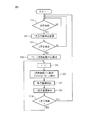
図1は本発明のタッチパネルの駆動シーケンスを示すフローチャートである。まず、ステップ101において、1点目が押下されているかどうかを判定する。タッチパネル上の1点が押下され、X側抵抗膜1とY側抵抗膜2とが接触すると、X側電極端子およびY側電極端子の電位が変化するため、いずれかの電位の変化から押下されたことを検出することができる。ここでは、タッチパネル上を2点押下された場合の検出方法について説明するが、2点同時に押下されることは、実際上はあり得ず、必ず1点目と2点目の押下のタイミングは、ずれるので、2点押下されるとしても最初は1点目のみが押下された状態となる。さらに、検出した電位から1点目の位置の座標を検出する。検出方法は上述した従来の検出方法と同様であるので、詳細な説明は省略する。1点目が押下されない場合は、待ち状態となる。
<Overall measurement sequence>
FIG. 1 is a flowchart showing a driving sequence of a touch panel according to the present invention. First, in
次に、1点目が押下された場合は、ステップ102において、検出した1点目の座標を記憶手段に記憶する。これは、2点目の座標を算出する際に、1点目の座標データを利用するためである。
Next, when the first point is pressed, in
次に、ステップ103において、2点目が押下されたか否かを判定する。この判定ステップの内容の詳細については後述する。2点目が押下されたことを検出した場合には、2点目の座標を算出する工程へ進む。2点目が検出されない場合は、ステップ101に戻って、1点目が検出されるまで待ち状態となる。
Next, in
2点目が検出されたときは、ステップ104〜106において、抵抗値が測定され、抵抗値から1点目と2点目との間の距離が算出される。算出方法は後述する。次に、ステップ107において、中点の座標を算出する。中点の座標は、2点が押下された状態で電圧を測定することにより行われる。次に、ステップ108において、2点間の距離と中点の座標から2点目の座標を算出する。
When the second point is detected, the resistance value is measured in
<本発明のタッチパネルの構成>
本発明のタッチパネルは、図2(a)に示すように対向する2辺に第1X電極端子3及び第2X電極端子4を備えた平面導電層からなるX側抵抗膜1が形成されたX側平板と、X電極端子とは直交する対向する2辺に第1Y電極端子5及び第2Y電極端子6を備えた平面導電層からなるY側抵抗膜2が形成されたY側平板とを対向させて配置した2枚の平板を備えている。第1X電極端子3及び第2X電極端子4にはそれぞれVcc及びOVが印加されており、少なくとも一方の電極には電位計(図示せず)が設けられており、同様に第1Y電極端子5及び第2Y電極端子6にはそれぞれVcc及びOVが印加されており、少なくとも一方の電極には電位計(図示せず)が設けられており、これらの電位計の測定値から2枚の平板が接する第1点目の位置を検出する位置検出手段を備えている。また、タッチパネルの外部には第1点目の位置を記憶する記憶手段を備えている。さらに、図2(a)に示すように、第1X電極端子3及び第2X電極端子4との間には抵抗測定手段12が設けられ、同様に第1Y電極端子5及び第2Y電極端子6との間にも抵抗測定手段(図示せず)が設けられ、これらは2枚の平板が接する第2点目を検出する検出手段を構成する。この抵抗測定手段の代わりに電流計を抵抗層と直列に配置して、電流値から抵抗を算出してもよい。また、タッチパネルの外部には、測定した抵抗値から2点間の距離を算出する2点間距離算出手段を備えている。また、2点が押下されている状態での電位から2点間の中点座標を検出することができ、電位計は中点座標検出手段を構成する。さらに、タッチパネル外部には2点間の距離と、中点座標とに基づいて第2点目の位置を算出する第2点目位置算出手段を備えている。
<Configuration of Touch Panel of the Present Invention>
As shown in FIG. 2A, the touch panel of the present invention has an
<2点目検出判定ステップ>
次に、個々のステップについて詳細に説明する。
タッチパネル上の1点が押下された状態で、2点目が押下されたことを検出するために、X側抵抗膜1の抵抗値を測定する。まず、比較のために、X側抵抗膜1の1点が押下された状態の抵抗について図2(a)、(b)を用いて説明する。抵抗の測定は、X側抵抗膜1の第1X電極端子3と第2X電極端子4との間に設置された抵抗測定手段12を用いて行われる。同図(a)に示すように、X側抵抗膜1の略中央部の1点がペン7によって押下されたとき、Y側抵抗膜2と接点8で接すると仮定する。このとき、X側抵抗膜1の抵抗は、第1X側抵抗9と第2X側抵抗10の和となり、X側抵抗膜1が押下されても変化しない。これは、Y側抵抗膜2が抵抗値の変化に寄与していないためである。同図(b)に示す等価回路からも明らかなように、Y側抵抗膜2の第1Y側抵抗14及び第2Y側抵抗15は、開放されており、Y側抵抗膜2が抵抗値の変化に寄与していないことがわかる。例えば、第1X側抵抗9及び第2X側抵抗10が共に100Ωであるとすると、測定される抵抗値は200Ωとなる。
<Second point detection determination step>
Next, each step will be described in detail.
In order to detect that the second point is pressed while one point on the touch panel is pressed, the resistance value of the
次に、X側抵抗膜1の中央部と端部の2点が押下された場合について、図3(a)、(b)を用いて説明する。X側抵抗膜1の略中央部をペン71で押下し、端部をペン72で押下する。このとき、ペン71によりX側抵抗膜1の接点13とY側抵抗膜2の接点8とが接触し、同様にペン72により、X側抵抗膜1の接点16とY側抵抗膜2の接点17とが接触し、これら2組の接点間の接触抵抗は無視できるほど小さいと仮定する。X側抵抗膜1の第1X電極端子3と第2X電極端子4との間に抵抗測定手段12を設置したときの等価回路を同図(b)に示す。第2X側抵抗10と第2Y側抵抗15とは、並列接続されており、第2X側抵抗10および第2Y側抵抗15がほぼ等しい抵抗値を持っているとすると、この並列抵抗の値は第2X側抵抗10の値の約半分となる。例えば、第1X側抵抗9及び第2X側抵抗10が共に100Ωであるとすると、測定される抵抗値は150Ωとなる。
このようにして、抵抗値を測定しておき、その大きさが小さくなったことを検出することにより、2点目が押下されたことを検出することができる。
Next, a case where two points of the central portion and the end portion of the
In this way, it is possible to detect that the second point has been pressed by measuring the resistance value and detecting that the size has decreased.
<2点間距離の検出>
2点目が押下されたことを検出した後は、測定した抵抗値から2点間の距離を算出する。X側抵抗膜1とY側抵抗膜2とが2点で接触すると、X側抵抗膜1の第1X電極端子3と第2X電極端子4との間の抵抗値が減少することは上述した通りであるが、減少する抵抗値は接触する2点間の距離にほぼ比例する。しかしながら、X側抵抗膜1及びY側抵抗膜2は有限の大きさを有しているために、抵抗値が平面上の位置により異なる場合も考えられる。また、X側抵抗膜1とY側抵抗膜2との接触抵抗は無視できることが望ましいが、ユーザ毎に押圧にばらつきが生じることがあり、接触抵抗を考慮に入れる必要も生じうる。
そこで、押下する2点の位置と抵抗値との関係を予め求めてテーブルを作成し、作成したテーブルに基づいて校正を行なうことが望ましい。例えば、図4(a)、(b)に示すように、X側抵抗膜1の両端近傍を押下する場合を考える。このとき、ペン71により、X側抵抗膜1の接点18とY側抵抗膜2の接点19とが接し、同様にX側抵抗膜1の接点16とY側抵抗膜2の接点17とが接すると仮定する。X側抵抗膜1の第1X電極端子3と第2X電極端子4との間に抵抗器12を設置したときの等価回路を同図(b)に示す。第1X側抵抗9及び第2X側抵抗10は、第1Y側抵抗14及び第2Y側抵抗15と並列接続される。ここで、第1X側抵抗9、第2X側抵抗10、第1Y側抵抗14、第2Y側抵抗15が全て100Ωであると仮定すると、抵抗測定手段12の抵抗値は100Ωとなる。
<Detection of distance between two points>
After detecting that the second point is pressed, the distance between the two points is calculated from the measured resistance value. As described above, when the
Therefore, it is desirable to obtain a relationship between the position of the two points to be pressed and the resistance value in advance, create a table, and perform calibration based on the created table. For example, as shown in FIGS. 4A and 4B, consider a case where the vicinity of both ends of the
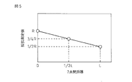
図2〜4に既に示したように、押下した2点の距離によって測定される抵抗値が決定されるため、測定した抵抗値から2点間の距離を求めることができる。測定した抵抗値と2点間の距離との関係を一般化してグラフ化すると図5のような関係となる。即ち、2点間の距離が非常に小さい場合は1点のみが押下された場合と等価と考えられ、X電極端子間の抵抗値は最大値であるRとなる。一方、2点間の距離が抵抗膜の1辺の距離Lと等しい距離だけ離れているとすると、X電極端子間の抵抗値は最大値の半分の1/2・Rとなる。同様に他の点についてもプロットすると図5のようになる。
このグラフをもとに、抵抗値から2点間距離を算出することができる。この場合、測定した抵抗値から2点間距離を計算式から求めてもよいが、校正用のテーブルを参照して求めてもよい。
As already shown in FIGS. 2 to 4, the measured resistance value is determined by the distance between the two pressed points, so that the distance between the two points can be obtained from the measured resistance value. When the relationship between the measured resistance value and the distance between two points is generalized and graphed, the relationship is as shown in FIG. That is, when the distance between the two points is very small, it is considered equivalent to the case where only one point is pressed, and the resistance value between the X electrode terminals is R which is the maximum value. On the other hand, if the distance between the two points is a distance equal to the distance L of one side of the resistive film, the resistance value between the X electrode terminals is ½ · R, which is half the maximum value. Similarly, other points are plotted as shown in FIG.
Based on this graph, the distance between two points can be calculated from the resistance value. In this case, the distance between the two points may be obtained from the measured resistance value by a calculation formula, or may be obtained by referring to a calibration table.
<中点座標の検出>
中点座標の検出は、図1のステップ107において、実行される。中点の座標は、2点が押下された状態で検出される電圧が、その2点間の中点を押下したときの電圧と等しくなる特性を利用している。この中点の座標は、2点目の座標を算出する際に利用される。
<Detection of midpoint coordinates>
The detection of the midpoint coordinates is executed in step 107 in FIG. The coordinates of the midpoint use the characteristic that the voltage detected when the two points are pressed becomes equal to the voltage when the midpoint between the two points is pressed. The coordinates of this midpoint are used when calculating the coordinates of the second point.
さらに、2点が接触したままの状態で移動するような場合には、中点の座標は、その中心を算出するのに利用される。例えば、地図等の画像上の任意の点をタッチパネルを介して指示するようなアプリケーション・ソフトに応用した場合、拡大したい領域を挟んで2点を選択し、2点間の距離を広げ、画像を拡大するような応用が考えられる。この場合、拡大したい領域を2点間の中点に設定することができる。 Further, in the case of moving while the two points are in contact, the coordinates of the midpoint are used to calculate the center. For example, when applied to application software that designates an arbitrary point on an image such as a map via a touch panel, two points are selected across an area to be enlarged, and the distance between the two points is increased. Applications that expand are conceivable. In this case, the area to be enlarged can be set at the midpoint between the two points.
<2点間距離を時間的に変化させる場合>
2点間の距離を時間的に変化させ、その動作を画像の拡大/縮小と連動させるようなアプリケーション・ソフトへの応用について説明する。2点間の距離の変化を知るためには、ある時刻tiにおける2点間の距離d(ti)を算出して、記憶しておき、tiより所定の時間だけ過去の時刻ti-1にける距離d(ti-1)と比較すればよい。ここで、2点間距離の時間的変化を検出する変化率検出手段によって検出した変化分Δd=d(ti)- d(ti-1)が正であれば、2点間距離は拡大していると判断でき、負であれば、2点間距離は縮小していると判断できる。
具体的には、図1のステップ104において、2点間距離の初期値を設定するために、i=0として、2点間距離の初期値d(t0)を算出する。次に、ステップ105において所定時刻経過後の2点間距離を規定するためにiを1つ増加させる。次に、2点間距離d(ti)を算出し、変化分Δd=d(ti)-d(ti-1)を算出する。例えば、i=1の場合はΔd=d(t1)-d(t0)となる。ここで、Δt=ti-ti-1は任意の値とすることができる。Δdを算出することで2点間距離が拡大しているか、縮小しているかを判定することができ、さらに、Δdの時間的変化Δd/Δtを算出すれば、その加速度を算出することができ、種々のアプリケーション・ソフトへの応用が可能となる。
<When changing the distance between two points over time>
An application to application software that changes the distance between two points in time and links the operation with enlargement / reduction of an image will be described. To know the variation of the distance between two points, calculates the distance d (t i) between two points at a certain time t i, the stored advance, predetermined time from t i only past time t i Compared with the distance d (t i-1 ) in -1 . Here, if the change Δd = d (t i ) −d (t i−1 ) detected by the change rate detecting means for detecting the temporal change in the distance between the two points is positive, the distance between the two points is increased. If it is negative, it can be determined that the distance between the two points is reduced.
Specifically, in
このように、2点間距離の変化に対応させて画像を拡大/縮小させるようなアプリケーション・ソフトにおいては、2点間の中心と、2点間の距離の拡大/縮小が重要な情報であり、2点の各座標は大きな意味を持たなくなる。本願発明では2点間距離を抵抗値から直接算出し、中点の座標は2点が押下された状態での電極端子の電位から算出可能であるので、このようなアプリケーション・ソフトに簡便に対応することができる。 Thus, in application software that enlarges / reduces an image in response to a change in the distance between two points, the center between the two points and the enlargement / reduction of the distance between the two points are important information. The coordinates of the two points are not significant. In the present invention, the distance between two points can be directly calculated from the resistance value, and the coordinates of the midpoint can be calculated from the potential of the electrode terminal when the two points are pressed. can do.
1 X側抵抗膜
2 Y側抵抗膜
3 第1X電極端子
4 第2X電極端子
5 第1Y電極端子
6 第2Y電極端子
7 ペン
71 ペン
72 ペン
8 接点
9 第1X側抵抗
10 第2X側抵抗
11 電圧計
12 抵抗測定手段
13 接点
14 第1Y側抵抗
15 第2Y側抵抗
16 接点
17 接点
18 接点
DESCRIPTION OF SYMBOLS 1 X side resistance film 2 Y
Claims (3)
電位を検出することで、前記2枚の平面導電層が接する位置を検出する位置検出手段と、
前記電極間の抵抗値を測定する抵抗測定手段と、
前記抵抗測定手段が測定した抵抗値に基づいて、平面導電層が接触した2点間の距離を算出する2点間距離算出手段と、
前記2点間距離の時間的変化を算出する変化率検出手段と、を有する抵抗式タッチパネル。 A resistive touch panel provided with two flat plates each having a planar conductive layer provided with electrodes on two opposite sides,
Position detecting means for detecting a position where the two planar conductive layers are in contact with each other by detecting a potential;
Resistance measuring means for measuring a resistance value between the electrodes;
A point-to-point distance calculating unit that calculates a distance between two points in contact with the planar conductive layer based on the resistance value measured by the resistance measuring unit;
And a change rate detecting means for calculating a temporal change in the distance between the two points.
前記導電層の電極間抵抗値を測定する抵抗測定手段と、
前記抵抗測定手段により測定された電極間抵抗値に基づいて、前記2枚の導電層が2点で接触したか否かを検出する検出手段と、
前記抵抗測定手段により測定された電極間抵抗値に基づいて、前記2点間の距離を算出する2点間距離算出手段と、
を備えたことを特徴とする抵抗式タッチパネル。 In a resistive touch panel having two conductive layers with electrodes on two opposite sides,
Resistance measuring means for measuring a resistance value between the electrodes of the conductive layer;
Detecting means for detecting whether or not the two conductive layers are in contact at two points based on the inter-electrode resistance value measured by the resistance measuring means;
A point-to-point distance calculating means for calculating a distance between the two points based on the inter-electrode resistance value measured by the resistance measuring means;
A resistive touch panel characterized by comprising:
前記導電層の電極間抵抗値を測定する抵抗測定手段と、
前記抵抗測定手段により測定された電極間抵抗値に基づいて、押下された2点間の距離を算出する2点間距離算出手段と、
検出された前記2枚の導電層間の電位に基づいて、押下された2点間の中点座標を検出する中点座標検出手段と、
を備えたことを特徴とする抵抗式タッチパネル。 In a resistive touch panel having two conductive layers with electrodes on two opposite sides,
Resistance measuring means for measuring a resistance value between the electrodes of the conductive layer;
A point-to-point distance calculating unit that calculates a distance between two pressed points based on the inter-electrode resistance value measured by the resistance measuring unit;
Midpoint coordinate detection means for detecting a midpoint coordinate between two pressed points based on the detected potential between the two conductive layers;
A resistive touch panel characterized by comprising:
Priority Applications (1)
| Application Number | Priority Date | Filing Date | Title |
|---|---|---|---|
| JP2012106255A JP2012168977A (en) | 2012-05-07 | 2012-05-07 | Resistance type touch panel |
Applications Claiming Priority (1)
| Application Number | Priority Date | Filing Date | Title |
|---|---|---|---|
| JP2012106255A JP2012168977A (en) | 2012-05-07 | 2012-05-07 | Resistance type touch panel |
Related Parent Applications (1)
| Application Number | Title | Priority Date | Filing Date |
|---|---|---|---|
| JP2007323350A Division JP5403905B2 (en) | 2007-12-14 | 2007-12-14 | Resistive touch panel |
Publications (1)
| Publication Number | Publication Date |
|---|---|
| JP2012168977A true JP2012168977A (en) | 2012-09-06 |
Family
ID=46973002
Family Applications (1)
| Application Number | Title | Priority Date | Filing Date |
|---|---|---|---|
| JP2012106255A Pending JP2012168977A (en) | 2012-05-07 | 2012-05-07 | Resistance type touch panel |
Country Status (1)
| Country | Link |
|---|---|
| JP (1) | JP2012168977A (en) |
Citations (4)
| Publication number | Priority date | Publication date | Assignee | Title |
|---|---|---|---|---|
| JPH07230352A (en) * | 1993-09-16 | 1995-08-29 | Hitachi Ltd | Touch position detecting device and touch instruction processor |
| JPH08241161A (en) * | 1995-03-01 | 1996-09-17 | Ricoh Co Ltd | Touch panel device |
| JP2000163031A (en) * | 1998-11-25 | 2000-06-16 | Seiko Epson Corp | Portable information equipment and information storage medium |
| JP2006034754A (en) * | 2004-07-29 | 2006-02-09 | Nintendo Co Ltd | Game apparatus using touch panel and game program |
-
2012
- 2012-05-07 JP JP2012106255A patent/JP2012168977A/en active Pending
Patent Citations (4)
| Publication number | Priority date | Publication date | Assignee | Title |
|---|---|---|---|---|
| JPH07230352A (en) * | 1993-09-16 | 1995-08-29 | Hitachi Ltd | Touch position detecting device and touch instruction processor |
| JPH08241161A (en) * | 1995-03-01 | 1996-09-17 | Ricoh Co Ltd | Touch panel device |
| JP2000163031A (en) * | 1998-11-25 | 2000-06-16 | Seiko Epson Corp | Portable information equipment and information storage medium |
| JP2006034754A (en) * | 2004-07-29 | 2006-02-09 | Nintendo Co Ltd | Game apparatus using touch panel and game program |
Similar Documents
| Publication | Publication Date | Title |
|---|---|---|
| US8120371B2 (en) | Object position sensing apparatus | |
| JP5403905B2 (en) | Resistive touch panel | |
| TWI521419B (en) | Method and device for correcting position error | |
| TW201508603A (en) | Sensing method based on capacitive touch device | |
| TWI398800B (en) | Touch panel and output method therefor | |
| JP2011221677A (en) | Electronic device and operation detection method | |
| TWI582673B (en) | A touch panel and a touch panel using the same, and a stylus for use with the film | |
| JP2010529546A (en) | Touch sensor and method for operating the touch sensor | |
| JP2009048233A (en) | Touch panel input device | |
| TW201516774A (en) | Method of determining touch point and touch pressure | |
| JP2005049978A (en) | Resistance film type touch panel | |
| TW201040822A (en) | Panel module and detection method | |
| TWI459267B (en) | Method for detecting touch spot of touch panel | |
| JP4508886B2 (en) | Resistive touch panel | |
| WO2015192597A1 (en) | Touch panel and driving method therefor and display device | |
| TW200935290A (en) | Resistive touch screen which can identify multi-touch | |
| US8730205B2 (en) | Touch panel input device and gesture detecting method | |
| JP2014106070A (en) | Pressed state detection method for pressure sensitive sheet, and pressure sensitive sheet | |
| TW201115448A (en) | Multi-touch measuring method for resistive touch panel | |
| JP2012168977A (en) | Resistance type touch panel | |
| JP2017062853A (en) | Capacitive sensor arrangement and touch sensor screen having capacitive sensor arrangement | |
| EP3531255B1 (en) | Touch panel device | |
| JP6104767B2 (en) | Cover material for touch panel and touch panel using the cover material | |
| US20120158332A1 (en) | Input apparatus and input method | |
| CN101901093B (en) | Panel module and detection method |
Legal Events
| Date | Code | Title | Description |
|---|---|---|---|
| A977 | Report on retrieval |
Free format text: JAPANESE INTERMEDIATE CODE: A971007 Effective date: 20130116 |
|
| A131 | Notification of reasons for refusal |
Free format text: JAPANESE INTERMEDIATE CODE: A131 Effective date: 20130205 |
|
| A521 | Written amendment |
Free format text: JAPANESE INTERMEDIATE CODE: A523 Effective date: 20130405 |
|
| A02 | Decision of refusal |
Free format text: JAPANESE INTERMEDIATE CODE: A02 Effective date: 20130827 |