JP2012167785A - Hydraulic shock absorber - Google Patents
Hydraulic shock absorber Download PDFInfo
- Publication number
- JP2012167785A JP2012167785A JP2011031082A JP2011031082A JP2012167785A JP 2012167785 A JP2012167785 A JP 2012167785A JP 2011031082 A JP2011031082 A JP 2011031082A JP 2011031082 A JP2011031082 A JP 2011031082A JP 2012167785 A JP2012167785 A JP 2012167785A
- Authority
- JP
- Japan
- Prior art keywords
- choke
- rod
- piston
- case member
- damping force
- Prior art date
- Legal status (The legal status is an assumption and is not a legal conclusion. Google has not performed a legal analysis and makes no representation as to the accuracy of the status listed.)
- Granted
Links
Images


Abstract
Description
この発明は、二輪車の前輪を懸架するフロントフォーク等の流体圧緩衝器の改良に関する。 The present invention relates to an improvement in a fluid pressure shock absorber such as a front fork that suspends a front wheel of a motorcycle.
流体圧緩衝器は、これまでに種々の提案がなされており、例えば、二輪車の車輪を懸架しながらその車輪に入力される路面振動を減衰するフロントフォークやリアクッションユニット等の懸架装置として利用される。 Various proposals have been made for fluid pressure shock absorbers so far. For example, the fluid pressure shock absorber is used as a suspension device such as a front fork or a rear cushion unit that suspends a wheel of a two-wheeled vehicle and attenuates road surface vibration input to the wheel. The
特許文献1には、従来のフロントフォークの構成が開示されており、このフロントフォークは、アウターチューブと、このアウターチューブ内に摺動自在に挿入されるインナーチューブとからなるフォーク本体を備える。そして、フロントフォークは、上記フォーク本体内に所定の減衰力を発生する正立型のダンパを収容し、フォーク本体とダンパとの間にリザーバ室を形成してこのリザーバ室内に作動流体を収容する。 Patent Document 1 discloses a configuration of a conventional front fork, and the front fork includes a fork body including an outer tube and an inner tube that is slidably inserted into the outer tube. The front fork accommodates an upright damper that generates a predetermined damping force in the fork main body, forms a reservoir chamber between the fork main body and the damper, and accommodates the working fluid in the reservoir chamber. .
上記ダンパは、特許文献1の図2に示すように、作動流体を収容するシリンダと、このシリンダ内に軸方向に移動自在に挿入されるロッドと、このロッドに保持されて上記シリンダ内周に外周を摺接させながら上記シリンダ内を二つの作用室に区画するピストンを備える。これらの作用室は、ロッド側に形成される伸側作用室と、ピストン側に形成される圧側作用室とからなる。 As shown in FIG. 2 of Patent Document 1, the damper includes a cylinder that contains a working fluid, a rod that is movably inserted in the cylinder in the axial direction, and a rod that is held by the rod to the inner periphery of the cylinder. A piston is provided that partitions the inside of the cylinder into two working chambers while sliding the outer periphery. These working chambers are composed of an extending side working chamber formed on the rod side and a pressure side working chamber formed on the piston side.
上記ピストンには、上記両作用室を連通する連通する連通路が形成されると共に、この連通路を作動流体が通過するとき所定の減衰力を発生する減衰バルブが装着される。 The piston is provided with a communicating passage that communicates the two working chambers, and a damping valve that generates a predetermined damping force when the working fluid passes through the communicating passage.
また、上記ダンパは、上記連通路を迂回して上記両作用室を連通するバイパス路と、このバイパス路の途中にオリフィスを形成するニードルとを備えてなる。このニードルは、背面側に設けられる調整手段で駆動されバイパス路内に出没して上記オリフィスの開口面積を変更する。 The damper includes a bypass passage that bypasses the communication passage and communicates the working chambers, and a needle that forms an orifice in the middle of the bypass passage. This needle is driven by adjusting means provided on the back surface side, and protrudes and disappears in the bypass path to change the opening area of the orifice.
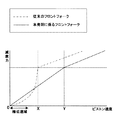
上記構成を備えることにより、図7中一点鎖線で示すように、ピストン速度が低く減衰バルブが作用しない場合(図7中0−X間)においては、作動流体が上記オリフィスを通過して減衰力を発生する。そして、ピストン速度が高まると(図7中X以上)、作動流体が減衰バルブを押し開き減衰力を発生する。 By providing the above configuration, as shown by the one-dot chain line in FIG. 7, when the piston speed is low and the damping valve does not act (between 0 and X in FIG. 7), the working fluid passes through the orifice and the damping force. Is generated. When the piston speed increases (X or more in FIG. 7), the working fluid pushes the damping valve and generates a damping force.
上記従来の流体圧緩衝器たるフロントフォークにおいて、上記オリフィスを備えることにより、ピストン速度が低い場合、上記オリフィスを介して作動流体が両作用室間を移動して減衰力を発生することが可能である点において有用であるが、以下の不具合を指摘される虞がある。 The front fork as the conventional fluid pressure buffer is provided with the orifice, so that when the piston speed is low, the working fluid can move between the working chambers through the orifice to generate a damping force. Although useful in some respects, the following problems may be pointed out.
即ち、ピストン速度が低い場合における減衰力は、オリフィスを作動流体が通過することにより発生し、図7中0−X間に示すように二乗特性を有する。したがって、ピストンが動き始める極低速域において減衰力を生じ難く、車両の乗り心地の悪化を招く。 That is, the damping force when the piston speed is low is generated when the working fluid passes through the orifice, and has a square characteristic as shown between 0 and X in FIG. Therefore, it is difficult to generate a damping force in an extremely low speed region where the piston starts to move, and the ride comfort of the vehicle is deteriorated.
そこで、本発明の目的は、極低速域においても減衰力を発生易くして減衰力応答性を向上することが可能な流体圧緩衝器を提供することである。 Accordingly, an object of the present invention is to provide a fluid pressure shock absorber that can easily generate a damping force even in an extremely low speed region and can improve the damping force responsiveness.
上記課題を解決するための手段は、作動流体を収容するシリンダと、このシリンダ内に軸方向に移動自在に挿入されるロッドと、このロッドに保持されて上記シリンダ内周に外周を摺接させながら上記シリンダ内を二つの作用室に区画するピストンと、このピストンに形成されて上記両作用室を連通する連通路と、この連通路を作動流体が通過するとき所定の減衰力を発生する減衰力発生手段と、上記連通路を迂回して上記両作用室を連通するバイパス路と、このバイパス路の途中に形成されるチョーク流路とを備える流体圧緩衝器において、外周にチョーク溝が形成されるチョーク部を有するチョーク部材と、内部に上記チョーク部材が挿入されて上記チョーク部材と軸方向に相対移動可能なケース部材と、上記チョーク部材と上記ケース部材とを相対移動させる調整手段とを備え、上記ケース部材は、上記チョーク部に摺接して上記チョーク溝との間に上記チョーク流路を形成するカバー部を有し、上記チョーク流路の長さは、上記チョーク部と上記カバー部との重複量によって決定されることである。 Means for solving the above-mentioned problems include a cylinder that contains a working fluid, a rod that is inserted into the cylinder so as to be movable in the axial direction, and an outer periphery that is held by the rod and that slides on the inner periphery of the cylinder. However, a piston that divides the inside of the cylinder into two working chambers, a communication passage that is formed in the piston and communicates with both working chambers, and a damping that generates a predetermined damping force when the working fluid passes through the communication passage. A choke groove is formed on the outer periphery of a fluid pressure shock absorber comprising a force generating means, a bypass passage that bypasses the communication passage and communicates the working chambers, and a choke passage formed in the middle of the bypass passage. A choke member having a choke portion, a case member into which the choke member is inserted and movable relative to the choke member in the axial direction, the choke member and the case Adjustment means for moving the material relative to each other, and the case member has a cover portion that is in sliding contact with the choke portion and forms the choke flow passage between the choke groove, and the length of the choke flow passage. This is determined by the amount of overlap between the choke portion and the cover portion.
本発明によれば、ピストン速度が低く減衰力発生手段が作動しない場合、チョーク流路を介して作動流体が両作用室間を移動して減衰力を発生するため、ピストン速度が低い場合における減衰力が略比例特性を有し、ピストンが動き始める極低速域においても減衰力を発生し易くして減衰力応答性を向上し、車両の乗り心地を向上することが可能となる。 According to the present invention, when the piston speed is low and the damping force generating means does not operate, the working fluid moves between the two working chambers via the choke channel to generate a damping force. The force has a substantially proportional characteristic, and it becomes easy to generate a damping force even in an extremely low speed region where the piston starts to move, thereby improving the damping force responsiveness and improving the riding comfort of the vehicle.
また、調整手段でチョーク部材とケース部材を相対移動させてチョーク部とカバー部との重複量を変更し、チョーク流路の長さを変えて減衰力を調整することが可能となる。 Further, it is possible to adjust the damping force by changing the overlap amount of the choke portion and the cover portion by moving the choke member and the case member relative to each other by the adjusting means, and changing the length of the choke flow path.
以下に本発明の一実施の形態を示す流体圧緩衝器について、図面を参照しながら説明する。いくつかの図面を通して付された同じ符号は、同じ部品かまたはそれに対応する部品を示す。 A fluid pressure shock absorber according to an embodiment of the present invention will be described below with reference to the drawings. The same reference numerals given throughout the several drawings indicate the same or corresponding parts.
本実施の形態に係る流体圧緩衝器は、自動二輪車の前輪を懸架して、路面の凹凸により前輪に入力される路面振動を減衰するフロントフォークである。 The fluid pressure shock absorber according to the present embodiment is a front fork that suspends a front wheel of a motorcycle and attenuates road surface vibration input to the front wheel due to unevenness of the road surface.
図示しないが、上記フロントフォークは、上端部をブリッジ機構で連結される左右一対のフォーク部材からなり、各フォーク部材の下端部を前輪の車軸に連結して前輪を挟むようにして懸架する。 Although not shown, the front fork is composed of a pair of left and right fork members whose upper end portions are connected by a bridge mechanism, and the lower ends of the fork members are connected to the axles of the front wheels and suspended so as to sandwich the front wheels.
また、上記ブリッジ機構は、同じく図示しないが、ハンドルに連結されるステアリングシャフトを有し、当該構成を備えることによりハンドル操作により前輪を転舵することが可能となる。 Further, although not shown, the bridge mechanism has a steering shaft coupled to a handle, and the front mechanism can be steered by operating the handle by including the configuration.
上記フォーク部材は、図1に示すように、アウターチューブ1と、このアウターチューブ1内に摺動自在に挿入されるインナーチューブ2とからなるフォーク本体を備え、内部にダンパ3を収容する。
As shown in FIG. 1, the fork member includes a fork main body including an outer tube 1 and an inner tube 2 that is slidably inserted into the outer tube 1, and accommodates a
上記ダンパ3は、作動流体を収容するシリンダ4と、このシリンダ4内に軸方向に移動自在に挿入されるロッド5と、このロッド5に保持されて上記シリンダ4内周に外周を摺接させながら上記シリンダ4内を二つの作用室A、Bに区画するピストン6と、このピストン6に形成されて上記両作用室A、Bを連通する連通路60と、この連通路60を作動流体が通過するとき所定の減衰力を発生する減衰力発生手段たる伸側減衰バルブVと、上記連通路60を迂回して上記両作用室を連通するバイパス路L1と、このバイパス路L1の途中に形成されるチョーク流路Tとを備える。
The
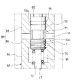
更に、ダンパ3は、図2に示すように、外周にチョーク溝70aが形成されるチョーク部70を有するチョーク部材7Aと、内部に上記チョーク部材7Aが挿入されて上記チョーク部材7Aと軸方向に相対移動可能なケース部材8Aと、上記チョーク部材7Aと上記ケース部材8Aとを相対移動させる調整手段9A(図1)とを備える。
Further, as shown in FIG. 2, the
そして、上記ケース部材8Aは、上記チョーク部70に摺接して上記チョーク溝70aとの間に上記チョーク流路Tを形成するカバー部たるカバー下部86を有し、上記チョーク流路Tの長さは、上記チョーク部70と上記カバー下部86との重複量によって決定される。
The
以下に、本実施の形態に係るフロントフォークの各構成部品について図1、2を参照しながら詳細に説明する。図1は、本実施の形態に係るフロントフォークを部分的に示す縦断面図であり、中心線より左側にチョーク流路を長くした状態を、中心線より右側にチョーク流路を短くした状態を示す。図2は、本実施の形態に係るフロントフォークのチョーク流路T周辺を示す部分拡大縦断面図である。 Hereinafter, each component of the front fork according to the present embodiment will be described in detail with reference to FIGS. FIG. 1 is a longitudinal sectional view partially showing a front fork according to the present embodiment, with a state in which a choke channel is elongated on the left side of the center line and a state in which the choke channel is shortened on the right side of the center line. Show. FIG. 2 is a partially enlarged longitudinal sectional view showing the vicinity of the choke channel T of the front fork according to the present embodiment.
アウターチューブ1とインナーチューブ2とからなるフォーク本体は、アウターチューブ1が車体側に、インナーチューブ2が車軸側に配置されて倒立型のフロントフォークを構成する。 The fork main body composed of the outer tube 1 and the inner tube 2 constitutes an inverted front fork in which the outer tube 1 is disposed on the vehicle body side and the inner tube 2 is disposed on the axle side.
上記フォーク本体は、図示しないがその上下端をキャップ部材とボトム部材とでそれぞれ封止されると共に、アウターチューブ1の図中下端部内周にインナーチューブ2外周に摺接するシール部材11が設けられてなり、当該構成を備えることにより、フォーク本体内に収容される作動流体や気体がフォーク本体外に漏れ出さない。
Although the fork body is not shown, the upper and lower ends thereof are sealed with a cap member and a bottom member, respectively, and a
更に、上記フォーク本体は、内部に路面振動を吸収する懸架ばねSと、所定の減衰力を発生するダンパ3とを収容する。当該構成を備えることにより、フロントフォークは、懸架ばねSによる路面振動の吸収に伴うフォーク本体の伸縮運動を上記ダンパ3で減衰することが可能となり、車両の乗り心地を良好にすることが可能となる。
Further, the fork main body accommodates therein a suspension spring S that absorbs road vibration and a
また、フォーク本体と上記ダンパ3との間にはリザーバ室Rが形成されて作動流体が貯留されてなり、図示しないが、その液面を介して上方に気体が封入されて気室が形成される。尚、この気室の内圧を同じく図示しないエアバルブで調整することが可能であり、この気室は、フォーク本体の伸縮に伴い膨縮して所定のばね反力を生じ、エアスプリングとして機能する。
Further, a reservoir chamber R is formed between the fork main body and the
上記フォーク本体内に収容されるダンパ3は、図1に示すように、インナーチューブ2の軸心部に起立するシリンダ4と、アウターチューブ1の軸心部に起立してフォーク本体の伸縮に伴い上記シリンダ4内を軸方向に移動するロッド5と、このロッド5の先端にケース部材8Aを介して保持されるピストン6とを備える。
As shown in FIG. 1, the
上記シリンダ4は、図中上端側に冠着する環状のロッドガイド40と、図中下端側に装着されるベース部材(図示せず)によってリザーバ室Rと区画されてなり、上記ロッドガイド40と上記ベース部材との間に作動流体で満たされる作動流体室が形成される。この作動流体室は、上記ピストン6により図中上下に区画され、図中上側に伸側作用室A、図中下側に圧側作用室Bが形成される。
The
ロッド5は、上記ロッドガイド40内周に外周を支持されながら上記シリンダ4の作動流体室内に出没し、その先端(図中下端)にケース部材8Aを介してピストン6を保持する。また、上記ロッド4は、筒状に形成されてなり、このロッド4の軸心部に調整手段9Aを構成するコントロールロッド90が軸方向に移動自在に挿入される。
The
上記ピストン6は、環状に形成されてなり、ケース部材8Aの外周にナットNを介して保持される。そして、ピストン6には、伸側作用室Aと圧側作用室Bとを連通する連通路60、61が形成され、この連通路60、61を開閉する伸側減衰バルブVとチェック弁Cが圧側作用室Bと伸側作用室Aに対向して設けられる。
The
上記連通路60、61は、伸側作用室Aと常に連通して出口を圧側作用室B側の伸側減衰バルブVで塞がれる伸側の連通路60と、圧側作用室Bと常に連通して出口を伸側作用室A側のチェック弁Cで塞がれる圧側の連通路61とを有する。
The
そして、伸側減衰バルブVは、作動流体が伸側作用室Aから圧側作用室Bへ移動することのみを許容し、チェック弁Cは、作動流体が圧側作用室Bから伸側作用室Aへ移動することのみを許容する。 The extension side damping valve V only allows the working fluid to move from the extension side working chamber A to the pressure side working chamber B, and the check valve C allows the working fluid to move from the pressure side working chamber B to the extension side working chamber A. Only allow movement.
また、図示しないが、シリンダ4の下端側に装着されるベース部材には、上記圧側作用室Bとリザーバ室Rとを連通する連通路が形成され、この連通路を開閉するチェック弁と圧側減衰バルブが圧側作用室Bとリザーバ室Rに対向して設けられる。
Although not shown, the base member mounted on the lower end side of the
上記ベース部材の連通路は、図示しないが、リザーバ室Rと常に連通して出口を圧側作用室B側のチェック弁で塞がれる伸側の連通路と、圧側作用室Bと常に連通して出口をリザーバ室R側の圧側減衰バルブで塞がれる圧側の連通路とを有する。 Although not shown in the drawing, the communication path of the base member is always in communication with the reservoir chamber R and the outlet side communication path where the outlet is blocked by the check valve on the pressure side working chamber B side, and the pressure side working chamber B. A pressure-side communication passage whose outlet is closed by a pressure-side damping valve on the reservoir chamber R side.
そして、ベース部材に設けられるチェック弁は、作動流体がリザーバ室Rから圧側作用室Bへ移動することのみを許容し、圧側減衰バルブは、作動流体が圧側作用室Bからリザーバ室Rへ移動することのみを許容する。 The check valve provided in the base member only allows the working fluid to move from the reservoir chamber R to the pressure side working chamber B, and the pressure side damping valve moves the working fluid from the pressure side working chamber B to the reservoir chamber R. Only allow that.
上記構成を備えることにより、フロントフォークの伸張工程においてロッド5がシリンダ4から退出するとき、伸側作用室Aが加圧されて作動流体が伸側減衰バルブVを押し開き、ピストン6の伸側の連通路60を通過して所定の減衰力を発生する。このとき、ロッド5の退出分作動流体室内で不足する作動流体がベース部材のチェック弁を開いて同伸側の連通路を通過する。
With the above configuration, when the
一方、フロントフォークの収縮工程においてロッド5がシリンダ4内に没入するとき、圧側作用室Bが加圧されて作動流体がピストン6のチェック弁Cを開いて同圧側の連通路61を通過する。このとき、ロッド5の没入分作動流体室内で余剰となる作動流体がベース部材の圧側減衰バルブを押し開き、同圧側の連通路を通過して所定の減衰力を発生する。
On the other hand, when the
即ち、本実施の形態において、伸側減衰バルブV及び圧側減衰バルブが減衰力発生手段を構成する。 That is, in the present embodiment, the extension side damping valve V and the compression side damping valve constitute a damping force generating means.
上記ピストン6をロッド5の先端に保持するケース部材8Aは、略筒状に形成されてロッド5の先端部(図中下端部)外周に螺合する環状の先端部材63の外周に螺合してなる。そして、ケース部材8Aは、内部にチョーク部材7Aを収容するケース部材本体(符示せず)と、このケース本体よりも小さい外径を有するピストン保持部81とを有する。尚、上記先端部材63内周には、コントロールロッド90外周に摺接するシール61が設けられ、このシール61で、先端部材63とケース部材8Aとの結合隙間から作動流体がロッド5の軸心部内に浸入することを防止する。また、上記ケース部材8Aには、軸方向に貫通する縦孔12と、この縦孔12と交差して径方向に貫通する横孔13が形成されてなる。
The
上記ケース本体は、筒状に形成されて図中上方から順に、先端部材63外周に螺合する螺合部82と、チョーク部材7Aが挿入されるチョーク挿入部83と、このチョーク挿入部83の内径よりも大きい内径を有する大内径部84とを備え、上記横孔13は、チョーク挿入部83の略中央側面に開穿される。図2に示すように、チョーク挿入部83において横孔13より図中上側をカバー上部85、同図中下側をカバー下部86とする。
The case body is formed in a cylindrical shape, and in order from the upper side in the drawing, is screwed to the outer periphery of the
上記ピストン保持部81は、図1に示すように、筒状に形成されて上記大内径部84よりも小さい外径を有し、上記大内径部84の図中下面外周部に段部73を形成してこの段部73とナットNとの間にピストン6を挟持する。また、上記ピストン保持部81の内部は、上記大内径部84の内部と連通して上記縦穴12の一部を構成する。
As shown in FIG. 1, the
上記チョーク挿入部83内に挿入されるチョーク部材7Aは、中空部(符示せず)を有してなり、図2に示すように、その外周における軸方向長さの略中央の位置に環状溝71を備え、環状溝71よりも図中上側に外周にシール72aを有する基部72が、環状溝71よりも図中下側に外周に螺旋状のチョーク溝70aを有するチョーク部70が形成される。
The
そして、基部72がカバー上部85に、環状溝71が横孔13に、チョーク部70がカバー下部86にそれぞれ対向して配置され、チョーク部70とカバー下部86とが重なり合う重複部のチョーク溝70aとカバー下部86内周との間にチョーク流路Tが形成される。即ち、本実施の形態において、カバー下部86が特許請求の範囲でいうところのカバー部に相当する。
The
尚、上記チョーク部材7Aに中空部を形成することにより軽量化することが可能となるが、中実に形成するとしても良い。また、チョーク溝70aを螺旋状に形成することにより、チョーク部70の軸方向長さを短くしながらチョーク溝70aを長く形成し、チョーク流路Tの長さを容易に確保することが可能となる。しかしながら、チョーク溝70aの形状は上記の限りではなく、カバー下部86との間にチョーク流路Tを形成することが可能な限りにおいて適宜形状を選択することが可能である。
In addition, although it becomes possible to reduce weight by forming a hollow part in the said
上記縦孔12におけるロッド5側の開口は、チョーク部材7Aに設けられるシール72a(図2)によって塞がれる。これにより、作動流体が横孔13、環状溝71、チョーク流路T、大内径部84及びピストン保持部81の内部を介して伸側作用室Aと圧側作用室Bとを移動することが可能となる。
The opening on the
つまり、横孔13、環状溝71、チョーク流路T、大内径部84及びピストン保持部81の内部でピストン6の連通路60、61を迂回するバイパス路L1を構成する。
That is, a bypass path L1 that bypasses the
また、バイパス路L1の途中にチョーク流路Tが形成されることから、このチョーク流路Tを通過した時に発生する減衰力が略比例特性を有し(図7中0−Y間)、ピストン6が動き始める極低速域においても減衰力を発生し易くして減衰力応答性を向上し、車両の乗り心地を向上することが可能となる。 Further, since the choke channel T is formed in the middle of the bypass channel L1, the damping force generated when passing through the choke channel T has a substantially proportional characteristic (between 0 and Y in FIG. 7), and the piston Even in the extremely low speed range where the 6 starts to move, it becomes easy to generate a damping force, thereby improving the damping force responsiveness and improving the riding comfort of the vehicle.
つまり、図7に示すように、ピストン速度が低速で減衰力発生手段(伸側減衰バルブV若しくは圧側減衰バルブ)が作動しない場合(図7中0−Y間)、作動流体がチョーク流路Tを通過することによる減衰力が発生する。そして、ピストン速度が高まると(図7中Y以上)、作動流体が減衰力発生手段を押し開くことにより減衰力が発生する。 That is, as shown in FIG. 7, when the piston speed is low and the damping force generating means (extension-side damping valve V or compression-side damping valve) does not operate (between 0 and Y in FIG. 7), the working fluid is choke flow path T. Damping force is generated by passing through. When the piston speed increases (Y or higher in FIG. 7), the working fluid pushes open the damping force generating means to generate a damping force.
上記チョーク部材7Aと上記ケース部材8Aは、調整手段9Aを介して相対移動することが可能であり、本実施の形態において、調整手段9Aでチョーク部材7Aを軸方向に移動させてチョーク部70とカバー下部86の重複量を変更し、チョーク流路Tの長さを調整する。
The
上記調整手段9Aは、図1に示すように、ロッド5の軸心部内に挿入されてチョーク部材7Aの基部72に当接するコントロールロッド90と、このコントロールロッド90の反ピストン側端部に対向してコントロールロッド90を軸方向に移動するアジャスタ(図示せず)と、チョーク部材7Aをコントロールロッド90側に附勢する附勢ばね91とを備える。
As shown in FIG. 1, the adjusting means 9A is opposed to the
上記構成を備えることにより、アジャスタを駆動してコントロールロッド90をピストン6側に前進させたとき(図1中右側)、附勢ばね91の附勢力に抗してチョーク部材7Aが図中下方に移動する。これにより、チョーク部70がカバー下部86から突出し、チョーク部70とカバー下部86との重複量が減少してチョーク流路Tが短くなり、作動流体がバイパス路L1を通過する際に発生する減衰力が小さくなる。
With the above configuration, when the adjuster is driven to advance the
一方、アジャスタを駆動してコントロールロッド90を後退させたとき(図1中左側)、附勢ばね91の附勢力に従いコントロールロッド90に当接するまでチョーク部材7Aが図中上方に移動する。これにより、チョーク部70がカバー下部86内に進入し、チョーク部70とカバー下部86との重複量が増してチョーク流路Tが長くなり、作動流体がバイパス路L1を通過する際に発生する減衰力が大きくなる。
On the other hand, when the adjuster is driven to retract the control rod 90 (left side in FIG. 1), the
つまり、調整手段9Aでチョーク部材7Aとケース部材8Aを相対移動させることにより、搭乗者が任意に減衰力の設定をすることが可能となる。
That is, it is possible for the occupant to arbitrarily set the damping force by relatively moving the
尚、本実施の形態において、アジャスタがコントロールロッド90を軸方向に移動してチョーク部材7Aを駆動し、特許請求の範囲でいうところの駆動部材に相当するがこの限りではなく、ソレノイドやモータ等を駆動部材とするとしても勿論良い。
In the present embodiment, the adjuster moves the
コントロールロッド90が最も後退した状態と比較して、コントロールロッド90がどれだけピストン6側に前進しているかをコントロールロッド90の移動量とした場合、本実施の形態において、上記移動量が大きくなるほどチョーク部70とカバー下部86の重複量が小さくなり、上記移動量と上記重複量が反比例する。従って、上記ロッド5の膨張率を上記コントロールロッド90の膨張率よりも大きく設定することにより、作動流体による温度変化を保障することが可能となる。
When the amount of movement of the
詳しくは、フロントフォークが減衰力の設定時よりも高温になった場合、熱膨張によりコントロールロッド90がロッド5に対して短くなり、実質的にコントロールロッド90が後退して移動量が小さくなる。これにより、チョーク部70とカバー下部86の重複量を増加させチョーク流路Tを長くして、温度上昇で作動流体の粘度が低下して減衰力が設定よりも低くなることを防止する。
Specifically, when the front fork becomes hotter than when the damping force is set, the
一方、フロントフォークが減衰力の設定時よりも低温になった場合、コントロールロッド90がロッド5に対して長くなり、実質的にコントロールロッド90が前進して移動量が大きくなる。これにより、チョーク部70とカバー下部86の重複量を減少させチョーク流路Tを短くして、温度低下で作動流体の粘度が上昇して減衰力が設定よりも高くなることを防止する。
On the other hand, when the temperature of the front fork becomes lower than when the damping force is set, the
つまり、ロッド5とコントロールロッド90の熱膨張率を適宜設定することにより、温度変化で作動流体の粘度が変化することによる減衰力への影響を吸収して温度保障をすることが可能となる。
That is, by appropriately setting the thermal expansion coefficients of the
上記ロッド5及びコントロールロッド90の膨張率の設定は、異なる材料を使用することにより実現することが可能であり、本実施の形態においては、例えば、ロッド5をアルミで、コントロールロッド90を鉄で形成するとすれば良い。
The setting of the expansion coefficient of the
尚、本実施の形態において、図3に示すように、チョーク挿入部83内周にチョーク部材7Aの環状溝71と対向すると共に横孔13が開穿される環状溝87を設け、コントロールロッド90の移動量とケース部70とチョーク下部86の重複量とを比例させるとしても良い。
In the present embodiment, as shown in FIG. 3, an
図3は、一実施の形態に係るフロントフォークの変更例を部分的に示す縦断面時であり、中心線より左側にチョーク流路Tを長くした状態を、中心線よりも右側にチョーク流路Tを短くした状態を示す。この場合においては、上記移動量と上記重複量が比例するため、ロッド5の膨張率をピストンロッド90の膨張率よりも低く設定することにより、温度保障をすることが可能となる。
FIG. 3 is a longitudinal sectional view partially showing a modification of the front fork according to the embodiment, and shows a state in which the choke channel T is elongated on the left side of the center line, and the choke channel on the right side of the center line. The state where T is shortened is shown. In this case, since the amount of movement and the amount of overlap are proportional, it is possible to ensure temperature by setting the expansion rate of the
詳しくは、フロントフォークが減衰力の設定時よりも高温になった場合、熱膨張によりコントロールロッド90がロッド5に対して長くなり、実質的にコントロールロッド90が前進して移動量が大きくなる。これにより、チョーク部70とカバー下部86の重複量を増加させチョーク流路Tを長くして、温度上昇で作動流体の粘度が低下して減衰力が設定よりも低くなることを防止する。
Specifically, when the front fork becomes hotter than when the damping force is set, the
一方、フロントフォークが減衰力の設定時よりも低温になった場合、コントロールロッド90がロッド5に対して短くなり、実質的にコントロールロッド90が後退して移動量が小さくなる。これにより、チョーク部70とカバー下部86の重複量を減少させチョーク流路Tを短くして、温度低下で作動流体の粘度が上昇して減衰力が設定よりも高くなることを防止する。
On the other hand, when the front fork becomes cooler than when the damping force is set, the
この場合において、ロッド5及びコントロールロッド90の膨張率の設定は、例えば、ロッドをアルミで、コントロールロッド90を鉄で形成するとすれば良く、また、図示しないが、コントロールロッド90に替えてロッド5のアジャスタ側及びピストン側開口を封止しながら軸方向に移動する上下一対の封止部材を設けて内部に作動流体を封入し、アジャスタからの作用を上記作動流体及び上記両封止部材を介してチョーク部材7Aに伝達するとしても良い。
In this case, the expansion rate of the
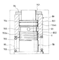
次に本発明の他の実施の形態を示す流体圧緩衝器について、図4、5を参照しながら説明する。図4は、本実施の形態に係るフロントフォークを部分的に示す縦断面図であり、中心線より左側にチョーク流路Tを長くした状態を、中心線より右側にチョーク流路Tを短くした状態を示す。図5は、本実施の形態に係るフロントフォークのチョーク流路T周辺を示す部分拡大縦断面図である。 Next, a fluid pressure shock absorber showing another embodiment of the present invention will be described with reference to FIGS. FIG. 4 is a longitudinal sectional view partially showing the front fork according to the present embodiment, in which the choke channel T is elongated on the left side of the center line, and the choke channel T is shortened on the right side of the center line. Indicates the state. FIG. 5 is a partially enlarged longitudinal sectional view showing the periphery of the choke channel T of the front fork according to the present embodiment.
他の実施の形態に係る流体圧緩衝器は、基本構造が上記一実施の形態と同様であり、ピストン6がロッド5の先端にチョーク部材7Bを介して保持されてなり、このチョーク部材7B外周に装着されるケース部材8Bを調整部材9で軸方向に移動してチョーク流路Tの長さを変更する点において相違する。そこで、以下に一実施の形態と相違する構成についてのみ説明し、同様の構成については、同一符合を付して詳細な説明を省略する。
The fluid pressure shock absorber according to another embodiment has the same basic structure as that of the above embodiment, and the
本実施の形態に係るチョーク部材7Bは、図中上方から順に、ロッド5の先端部に螺合するロッド連結部701と、ケース部材8Bが外周に装着されるチョーク本体702と、ナットNを介してピストン6を外周に保持するピストン保持部703とを備える。
The choke member 7B according to the present embodiment includes, in order from the top in the figure, a
ロッド連結部701は、図中上部に形成される螺子穴701aと、図中下部に形成されて径方向に貫通する径孔701bとを備え、この径孔701bは、上記螺子穴701aの底部に開穿される軸穴701cを介して上記螺子穴701aと連通する。
The
チョーク本体702は、有天筒状に形成されて図中上方から順に、外周にシール704aを有する基部704と、外周に螺旋状のチョーク溝700a(図5)を有するチョーク部700と、胴部705とを備え、上記基部704と上記チョーク部700との境界に環状溝706が形成される。また、この環状溝706には、チョーク本体702内部に向けて径方向に開穿される横孔23が設けられる。尚、上記チョーク溝700aの形状は、一実施の形態のチョーク溝70aと同様に適宜選択することが可能である。
The choke main body 702 is formed in a cylindrical shape, and in order from the top in the figure, a
ピストン保持部703は、筒状に形成されて上記胴部705よりも小さい外径を有し、上記胴部705の図中下面外周部に段部707を形成してこの段部707とナットNとの間にピストン6を挟持する。また、このピストン保持部703の内部は、チョーク本体702の内部と連通してチョーク本体702の内部と共に縦穴22を構成する。
The
上記チョーク本体702外周に装着されるケース部材8Bは、調整手段9によりチョーク本体702外周を軸方向に移動可能であり、図5に示すように、その図中上部801内周がチョーク部材7Bのシール704aを介して基部704に密接し、図中下部802がチョーク部700と重なってその内周とチョーク溝700aとの間にチョーク流路Tを形成する。つまり、本実施の形態において、ケース部材8Bの下部802が特許請求の範囲でいうところのカバー部に相当する。
The
上記構成を備えることにより、作動流体がチョーク流路T、環状溝706、横孔23及び縦穴22を介して伸側作用室Aと圧側作用室Bとの間を移動することが可能となり、チョーク流路T、環状溝706、横孔23及び縦穴22でピストン6の連通路60、61を迂回するバイパス路L2を構成する。
With the above configuration, the working fluid can move between the expansion side working chamber A and the compression side working chamber B via the choke flow path T, the
また、バイパス路L2の途中にチョーク流路Tが形成されることから、このチョーク流路Tを通過した時に発生する減衰力が略比例特性を有し(図7中0−Y間)、一実施の形態と同様に、ピストン6が動き始める極低速域においても減衰力を発生し易くして減衰力応答性を向上し、車両の乗り心地を向上することが可能となる。
Further, since the choke channel T is formed in the middle of the bypass channel L2, the damping force generated when passing through the choke channel T has a substantially proportional characteristic (between 0 and Y in FIG. 7). Similar to the embodiment, it is possible to easily generate a damping force even in an extremely low speed region where the
上記チョーク部材7Bと上記ケース部材8Bは、調整手段9Bを介して相対移動することが可能であり、本実施の形態において、調整手段9Bでケース部材8Bを軸方向に移動させてチョーク部7Bとケース部8B材の下部802の重複量を変更し、チョーク流路Tの長さを調整する。
The choke member 7B and the
上記調整手段9Bは、図4に示すように、ロッド5の軸心部内に挿入されるコントロールロッド90と、このコントロールロッド90の反ピストン側端部に対向してコントロールロッド90を軸方向に移動するアジャスタ(図示せず)と、ロッド5の軸心部内に挿入されて背面に上記コントロールロッド90が当接し頭部が径孔701b内に突出する先端ロッド93と、この先端ロッド93とケース部材8Bとの間に挟持される受け板94と、ケース部材8Bをコントロールロッド90側に附勢する附勢ばね95とを備える。尚、上記先端ロッド93の外周がシール(符示せず)を介してロッド5内周に摺接し、このシールが伸側作用室A内の作動流体がロッド5の軸心部に浸入することを防止する。
As shown in FIG. 4, the adjusting means 9 </ b> B moves the
上記構成を備えることにより、アジャスタを駆動してコントロールロッド90をピストン6から離れる方向に後退させたとき(図4中右側)、附勢ばね95の附勢力に従い先端ロッド93がコントロールロッド90に当接するまで受け板94及びケース部材8Bが図中上方に移動する。これにより、チョーク部700とケース部材8Bの下部802との重複量が減少してチョーク流路Tが短くなり、作動流体がバイパス路L2を通過する際に発生する減衰力が小さくなる。
With the above configuration, when the adjuster is driven to retract the
一方、アジャスタを駆動してコントロールロッド90を前進させたとき(図4中左側)、附勢ばね95の附勢力に抗してケース部材8Bが図中下方に移動する。これにより、チョーク部700とケース部材8Bの下部802との重複量が増してチョーク流路Tが長くなり、作動流体がバイパス路L2を通過する際に発生する減衰力が大きくなる。
On the other hand, when the adjuster is driven to advance the control rod 90 (left side in FIG. 4), the
つまり、調整手段9Bでチョーク部材7Bとケース部材8Bを相対移動させることにより、ドライバーが任意に減衰力の設定をすることが可能となる。
That is, the driver can arbitrarily set the damping force by relatively moving the choke member 7B and the
尚、本実施の形態において、アジャスタがコントロールロッド90を軸方向に移動してケース部材8Bを駆動し、特許請求の範囲でいうところの駆動部材に相当するがこの限りではなく、一実施の形態と同様にソレノイドやモータ等を駆動部材とするとしても勿論良い。
In the present embodiment, the adjuster moves the
本実施の形態において、コントロールロッド90の移動量がチョーク部700とケース部材8Bの下部802との重複量と比例するため、ロッド5の膨張率をコントロールロッド90の膨張率よりも小さく設定することにより、温度保障をすることが可能となる。
In the present embodiment, since the amount of movement of the
詳しくは、フロントフォークが減衰力の設定時よりも高温になった場合、熱膨張によりコントロールロッド90がロッド5に対して長くなり、実質的にコントロールロッド90が前進して移動量が大きくなる。これにより、チョーク部700とケース部材8Bの下部802の重複量を増加させチョーク流路Tを長くして、温度上昇で作動流体の粘度が低下して減衰力が設定よりも低くなることを防止する。
Specifically, when the front fork becomes hotter than when the damping force is set, the
一方、フロントフォークが減衰力の設定時よりも低温になった場合、コントロールロッド90がロッド5に対して短くなり、実質的にコントロールロッド90が後退して移動量が小さくなる。これにより、チョーク部700とケース部材8Bの下部802の重複量を減少させチョーク流路Tを短くして、温度低下で作動流体の粘度が上昇して減衰力が設定よりも高くなることを防止する。
On the other hand, when the front fork becomes cooler than when the damping force is set, the
尚、上記他の実施の形態において、図6に示すように、ケース本体8B内周と、チョーク部材7Bのチョーク部700の図中下側外周に環状溝708、800を形成して、コントロールロッド90の移動量とチョーク部700とケース部材8Bの下部との重複量を反比例させるとしても良い。
In the other embodiment, as shown in FIG. 6,
図6は、他の実施の形態に係るフロントフォークの変更例を部分的に示す縦断面図であり、中心線よりも左側にチョーク流路Tを長くした状態を、中心線よりも右側にチョーク流路Tを短くした状態を示す。この場合においては、ロッド5の膨張率をピストンロッド90の膨張率よりも高く設定することにより、温度保障をすることが可能となる。
FIG. 6 is a longitudinal sectional view partially showing a modified example of the front fork according to another embodiment, in which the choke channel T is elongated on the left side of the center line, and the choke on the right side of the center line. The state which shortened the flow path T is shown. In this case, the temperature can be ensured by setting the expansion rate of the
詳しくは、フロントフォークが減衰力の設定時よりも高温になった場合、熱膨張によりコントロールロッド90がロッド5に対して短くなり、実質的にコントロールロッド90が後退して移動量が小さくなる。これにより、チョーク部700とケース部材8Bの下部802の重複量を増加させチョーク流路Tを長くして、温度上昇で作動流体の粘度が低下して減衰力が設定よりも低くなることを防止する。
Specifically, when the front fork becomes hotter than when the damping force is set, the
一方、フロントフォークが減衰力の設定時よりも低温となった場合、コントロールロッド90がロッド5に対して長くなり、実質的にコントロールロッド90が前進し、コントロールロッド90の移動量が大きくなる。これにより、チョーク部700とケース部材8Bの下部802の重複量を減少させチョーク流路Tを短くして、温度低下で作動流体の粘度が上昇して減衰力が設定よりも高くなることを防止する。
On the other hand, when the front fork becomes cooler than when the damping force is set, the
以上、本発明の好ましい実施の形態を説明したが、特許請求の範囲から逸脱することなく改造、変形及び変更を行うことができることは理解すべきである。 While the preferred embodiment of the present invention has been described above, it should be understood that modifications, variations and changes may be made without departing from the scope of the claims.
例えば、上記実施の形態においては、フロントフォークに本発明を具現化するとしたがこの限りではなく、例えば、リアクッションユニットなど他の流体圧緩衝器に具現化するとしても良いことは勿論である。 For example, in the above embodiment, the present invention is embodied in the front fork. However, the present invention is not limited to this. For example, the present invention may be embodied in another fluid pressure buffer such as a rear cushion unit.
また、上記実施の形態においては、フロントフォーク及びダンパが倒立型に設定されるとしたが、正立型に設定されるとしても良く、両ロッド型のダンパに本発明が具現化されるとしても良い。 In the above embodiment, the front fork and the damper are set upside down. However, the front fork and the damper may be set upright, and even if the present invention is embodied in a double rod type damper. good.
A 伸側作用室
B 圧側作用室
C チェック弁
L1、L2 バイパス路
R リザーバ室
T チョーク流路
V 伸側減衰バルブ
1 アウターチューブ
2 インナーチューブ
3 ダンパ
4 シリンダ
5 ロッド
6 ピストン
7A、7B チョーク部材
8A、8B ケース部材
9A、9B 調整手段
11 シール部材
70、700 チョーク部
70a、700a チョーク溝
90 コントロールロッド
A Stretching side working chamber B Pressure side working chamber C Check valves L1, L2 Bypass passage R Reservoir chamber T Choke passage V Stretching side damping valve 1 Outer tube 2
Claims (5)
外周にチョーク溝が形成されるチョーク部を有するチョーク部材と、内部に上記チョーク部材が挿入されて上記チョーク部材と軸方向に相対移動可能なケース部材と、上記チョーク部材と上記ケース部材とを相対移動させる調整手段とを備え、
上記ケース部材は、上記チョーク部に摺接して上記チョーク溝との間に上記チョーク流路を形成するカバー部を有し、上記チョーク流路の長さは、上記チョーク部と上記カバー部との重複量によって決定されることを特徴とする流体圧緩衝器。 A cylinder that contains the working fluid, a rod that is inserted into the cylinder so as to be movable in the axial direction, and the inside of the cylinder is divided into two working chambers while being held by the rod and in sliding contact with the inner periphery of the cylinder. A partitioning piston, a communicating passage formed in the piston and communicating with the two working chambers, a damping force generating means for generating a predetermined damping force when the working fluid passes through the communicating passage, and bypassing the communicating passage In a fluid pressure shock absorber comprising a bypass passage communicating the two working chambers and a choke passage formed in the middle of the bypass passage,
A choke member having a choke portion formed with a choke groove on the outer periphery; a case member in which the choke member is inserted and movable relative to the choke member in the axial direction; and the choke member and the case member Adjusting means for moving,
The case member has a cover portion that is in sliding contact with the choke portion and forms the choke channel between the choke groove, and the choke channel has a length between the choke portion and the cover portion. A fluid pressure buffer characterized by being determined by the amount of overlap.
上記チョーク部材が上記調整手段により上記ケース部材内を軸方向に移動することを特徴とする請求項1または請求項2に記載の流体圧緩衝器。 The piston is held by the rod via the case member, and the bypass path is formed in the case member.
The fluid pressure shock absorber according to claim 1 or 2, wherein the choke member is moved in the axial direction in the case member by the adjusting means.
上記ケース部材が上記調整手段により上記チョーク部材の外周を軸方向に移動することを特徴とする請求項1または請求項2に記載の流体圧緩衝器。 The piston is held by the rod via the choke member, and the bypass path is formed between the choke member and the choke member and the case member,
The fluid pressure shock absorber according to claim 1 or 2, wherein the case member is moved in an axial direction on an outer periphery of the choke member by the adjusting means.
コントロールロッドの移動量が上記重複量と比例するとき、上記ロッドの膨張率が上記コントロールロッドの膨張率よりも小さく設定され、コントロールロッドの移動量が上記重複量と反比例するとき、上記ロッドの膨張率が上記コントロールロッドの膨張率よりも大きく設定されることを特徴とする請求項1から請求項4の何れかに記載の流体圧緩衝器。 The adjusting means includes a control rod that is inserted into an axial center portion of the rod formed in a cylindrical shape, and a drive member that moves the control rod in the axial direction to drive the case member or the choke member. And
When the movement amount of the control rod is proportional to the overlap amount, the expansion rate of the rod is set smaller than the expansion rate of the control rod, and when the movement amount of the control rod is inversely proportional to the overlap amount, the expansion of the rod The fluid pressure buffer according to any one of claims 1 to 4, wherein a rate is set to be larger than an expansion rate of the control rod.
Priority Applications (1)
| Application Number | Priority Date | Filing Date | Title |
|---|---|---|---|
| JP2011031082A JP5681518B2 (en) | 2011-02-16 | 2011-02-16 | Fluid pressure buffer |
Applications Claiming Priority (1)
| Application Number | Priority Date | Filing Date | Title |
|---|---|---|---|
| JP2011031082A JP5681518B2 (en) | 2011-02-16 | 2011-02-16 | Fluid pressure buffer |
Publications (2)
| Publication Number | Publication Date |
|---|---|
| JP2012167785A true JP2012167785A (en) | 2012-09-06 |
| JP5681518B2 JP5681518B2 (en) | 2015-03-11 |
Family
ID=46972128
Family Applications (1)
| Application Number | Title | Priority Date | Filing Date |
|---|---|---|---|
| JP2011031082A Expired - Fee Related JP5681518B2 (en) | 2011-02-16 | 2011-02-16 | Fluid pressure buffer |
Country Status (1)
| Country | Link |
|---|---|
| JP (1) | JP5681518B2 (en) |
Cited By (4)
| Publication number | Priority date | Publication date | Assignee | Title |
|---|---|---|---|---|
| WO2014157370A1 (en) | 2013-03-28 | 2014-10-02 | カヤバ工業株式会社 | Hydraulic shock absorber and method of injecting work fluid into hydraulic shock absorber |
| JP2017048826A (en) * | 2015-08-31 | 2017-03-09 | 日立オートモティブシステムズ株式会社 | Shock absorber |
| CN107407363A (en) * | 2015-04-02 | 2017-11-28 | Kyb摩托车减震器株式会社 | Front fork |
| DE112016004167T5 (en) | 2015-09-14 | 2018-05-24 | Kyb Corporation | SHOCK |
Citations (2)
| Publication number | Priority date | Publication date | Assignee | Title |
|---|---|---|---|---|
| JPS63172033A (en) * | 1986-12-24 | 1988-07-15 | ローベルト・ボツシユ・ゲゼルシヤフト・ミツト・ベシユレンクテル・ハフツング | Kinetic shock absorber |
| JPH11166574A (en) * | 1997-10-02 | 1999-06-22 | Kayaba Ind Co Ltd | Damping force generating structure |
-
2011
- 2011-02-16 JP JP2011031082A patent/JP5681518B2/en not_active Expired - Fee Related
Patent Citations (2)
| Publication number | Priority date | Publication date | Assignee | Title |
|---|---|---|---|---|
| JPS63172033A (en) * | 1986-12-24 | 1988-07-15 | ローベルト・ボツシユ・ゲゼルシヤフト・ミツト・ベシユレンクテル・ハフツング | Kinetic shock absorber |
| JPH11166574A (en) * | 1997-10-02 | 1999-06-22 | Kayaba Ind Co Ltd | Damping force generating structure |
Cited By (7)
| Publication number | Priority date | Publication date | Assignee | Title |
|---|---|---|---|---|
| WO2014157370A1 (en) | 2013-03-28 | 2014-10-02 | カヤバ工業株式会社 | Hydraulic shock absorber and method of injecting work fluid into hydraulic shock absorber |
| US9604694B2 (en) | 2013-03-28 | 2017-03-28 | Kyb Corporation | Hydraulic shock absorber and method for injecting operating liquid into hydraulic shock absorber |
| CN107407363A (en) * | 2015-04-02 | 2017-11-28 | Kyb摩托车减震器株式会社 | Front fork |
| US10458507B2 (en) | 2015-04-02 | 2019-10-29 | Kyb Motorcycle Suspension Co., Ltd. | Front fork |
| JP2017048826A (en) * | 2015-08-31 | 2017-03-09 | 日立オートモティブシステムズ株式会社 | Shock absorber |
| DE112016004167T5 (en) | 2015-09-14 | 2018-05-24 | Kyb Corporation | SHOCK |
| US10578185B2 (en) | 2015-09-14 | 2020-03-03 | Kyb Corporation | Shock absorber |
Also Published As
| Publication number | Publication date |
|---|---|
| JP5681518B2 (en) | 2015-03-11 |
Similar Documents
| Publication | Publication Date | Title |
|---|---|---|
| JP2010084831A (en) | Damper | |
| JP5681518B2 (en) | Fluid pressure buffer | |
| US9581217B2 (en) | Shock absorber | |
| WO2014119621A1 (en) | Damper | |
| JP5662862B2 (en) | Shock absorber | |
| JP5156689B2 (en) | Front fork | |
| JP4137541B2 (en) | Hydraulic shock absorber for vehicles | |
| US9604694B2 (en) | Hydraulic shock absorber and method for injecting operating liquid into hydraulic shock absorber | |
| JP5368858B2 (en) | damper | |
| JP5452372B2 (en) | Fluid pressure buffer | |
| JP6438339B2 (en) | Hydraulic shock absorber | |
| JP6010496B2 (en) | Shock absorber | |
| JP5113116B2 (en) | Attenuator structure | |
| JP5395746B2 (en) | Fluid pressure buffer | |
| JP6637626B1 (en) | Hydraulic shock absorber | |
| JP5687938B2 (en) | Shock absorber | |
| JP5530263B2 (en) | Fluid pressure buffer | |
| JP2009264488A (en) | Front fork | |
| JP2012077886A (en) | Fluid pressure buffer | |
| JP6444799B2 (en) | Damping force generator | |
| JP5406567B2 (en) | Hydraulic shock absorber | |
| KR101263455B1 (en) | Damping force controlling shock absorber | |
| JP2010038171A (en) | Hydraulic shock absorber | |
| KR20110085202A (en) | Valve structure of shock absorber | |
| JP2004052878A (en) | Hydraulic shock absorber for vehicle |
Legal Events
| Date | Code | Title | Description |
|---|---|---|---|
| A621 | Written request for application examination |
Free format text: JAPANESE INTERMEDIATE CODE: A621 Effective date: 20130826 |
|
| A977 | Report on retrieval |
Free format text: JAPANESE INTERMEDIATE CODE: A971007 Effective date: 20140220 |
|
| A131 | Notification of reasons for refusal |
Free format text: JAPANESE INTERMEDIATE CODE: A131 Effective date: 20140729 |
|
| A521 | Written amendment |
Free format text: JAPANESE INTERMEDIATE CODE: A523 Effective date: 20140926 |
|
| TRDD | Decision of grant or rejection written | ||
| A01 | Written decision to grant a patent or to grant a registration (utility model) |
Free format text: JAPANESE INTERMEDIATE CODE: A01 Effective date: 20141224 |
|
| A61 | First payment of annual fees (during grant procedure) |
Free format text: JAPANESE INTERMEDIATE CODE: A61 Effective date: 20150109 |
|
| R151 | Written notification of patent or utility model registration |
Ref document number: 5681518 Country of ref document: JP Free format text: JAPANESE INTERMEDIATE CODE: R151 |
|
| S533 | Written request for registration of change of name |
Free format text: JAPANESE INTERMEDIATE CODE: R313533 |
|
| R350 | Written notification of registration of transfer |
Free format text: JAPANESE INTERMEDIATE CODE: R350 |
|
| LAPS | Cancellation because of no payment of annual fees |