JP2012167752A - One-way clutch - Google Patents
One-way clutch Download PDFInfo
- Publication number
- JP2012167752A JP2012167752A JP2011029709A JP2011029709A JP2012167752A JP 2012167752 A JP2012167752 A JP 2012167752A JP 2011029709 A JP2011029709 A JP 2011029709A JP 2011029709 A JP2011029709 A JP 2011029709A JP 2012167752 A JP2012167752 A JP 2012167752A
- Authority
- JP
- Japan
- Prior art keywords
- coil springs
- coil spring
- rollers
- way clutch
- accommodating portion
- Prior art date
- Legal status (The legal status is an assumption and is not a legal conclusion. Google has not performed a legal analysis and makes no representation as to the accuracy of the status listed.)
- Pending
Links
Images
Landscapes
- Braking Arrangements (AREA)
Abstract
【課題】組み立て工程を簡易とすることで、組み立て工数を低減することができる一方向クラッチを提供する。
【解決手段】本発明の一方向クラッチ1は、内輪としての回転軸Sの外周外方に配置された外輪2と、これらの間に形成される複数のくさび状空間Kにそれぞれ配置された複数のころ3と、複数のころ3をそれぞれ複数のくさび状空間Kにおける狭小方向へ付勢する複数のコイルばね6と、ころ3を保持する保持器4とを備えている。保持器4は、複数のころ3を保持するポケット5、及びポケット5に開口し複数のコイルばね6の外側を包囲して当該複数のコイルばね6を収容する複数の収容部7と、を有している。収容部7には、複数のコイルばね6が収容部7から抜けるのを防止する収容部側突起8が形成されている。
【選択図】 図2A one-way clutch capable of reducing the number of assembly steps by simplifying an assembly process.
A one-way clutch 1 according to the present invention includes a plurality of outer rings 2 arranged on the outer periphery of a rotating shaft S as an inner ring, and a plurality of wedge-shaped spaces K formed therebetween. And a plurality of coil springs 6 for urging the plurality of rollers 3 in a narrow direction in the plurality of wedge-shaped spaces K, and a cage 4 for holding the rollers 3. The cage 4 includes a pocket 5 that holds the plurality of rollers 3, and a plurality of accommodating portions 7 that open to the pocket 5 and surround the outside of the plurality of coil springs 6 and accommodate the plurality of coil springs 6. is doing. The accommodating portion 7 is formed with an accommodating portion-side protrusion 8 that prevents the plurality of coil springs 6 from coming out of the accommodating portion 7.
[Selection] Figure 2
Description
本発明は、一方向クラッチに関する。 The present invention relates to a one-way clutch.
回転軸の回転方向に応じてその回転力の断続を行う機械要素である一方向クラッチには、例えば、特許文献1に記載されているように、内輪と、前記内輪の外周外方に配置された外輪と、前記内外輪間に形成される複数のくさび状空間にそれぞれ配置された複数のころと、前記複数のころをそれぞれ前記複数のくさび状空間における狭小方向へ付勢する複数のコイルばねとを備えたものがある。
前記コイルばねは、前記複数のころを保持するための複数のポケットを有する環状の保持器に設けられた当該コイルばねを収容する収容部に配置されている。前記収容部は、各ポケットに開口した孔状に形成されており、コイルばねの外周側を包囲して収容し、当該コイルばねを前記ころに対して付勢する方向にガイドしている。
A one-way clutch, which is a mechanical element that interrupts the rotational force in accordance with the rotational direction of the rotary shaft, is arranged, for example, on the outer periphery of the inner ring and the inner ring as described in
The said coil spring is arrange | positioned at the accommodating part which accommodates the said coil spring provided in the cyclic | annular holder | retainer which has a some pocket for hold | maintaining the said some roller. The accommodating portion is formed in a hole shape opened in each pocket, encloses and accommodates the outer peripheral side of the coil spring, and guides the coil spring in a direction of urging the roller.
上記一方向クラッチを組み立てるには、まず前記内輪の外周側に保持器を配置し、保持器の収容部にコイルばねを収容した上で、ころを保持器のポケット内に配置する。その後、内輪外周側に外輪を外嵌し組み立てを終える。
ここで、ころを保持器に配置するには、まず予めコイルばねを収容部に収容しておく必要がある。しかし、コイルばねは、収容部内に特に固定されることなく収容されているので、容易に抜け落ちてしまう。このため、コイルばねを収容部に収容した後すぐに、対応するポケットにころを配置する。これにより、コイルばねを収容部内にころを付勢した状態で留めることができる。よって、ころを配置する際には、各ポケットごとに順次、コイルばね及びころを収容配置していく必要がある。
このため、例えば、自動組み立て装置で当該一方向クラッチを組み立てようとすると、一カ所のポケットごとに、ころ及びコイルばねといった二種類の部品をハンドリングして配置するという工程を採ることになるため、その工程が複雑になり、多くの工数を要していた。
In order to assemble the one-way clutch, first, a cage is arranged on the outer peripheral side of the inner ring, a coil spring is accommodated in an accommodation portion of the cage, and a roller is arranged in a pocket of the cage. Thereafter, the outer ring is fitted on the outer circumference side of the inner ring to complete the assembly.
Here, in order to arrange the rollers in the cage, it is necessary to first house the coil spring in the housing portion in advance. However, since the coil spring is accommodated without being particularly fixed in the accommodating portion, it easily falls off. For this reason, immediately after accommodating a coil spring in an accommodating part, a roller is arrange | positioned to a corresponding pocket. Thereby, a coil spring can be fastened in the state which urged | biased the roller in the accommodating part. Therefore, when arranging the rollers, it is necessary to sequentially accommodate and arrange the coil springs and rollers for each pocket.
For this reason, for example, when trying to assemble the one-way clutch with an automatic assembly device, it takes a process of handling and arranging two types of parts such as rollers and coil springs for each pocket at one place. The process became complicated and required a lot of man-hours.
また、手作業で組み立てる場合においても、外輪を取り付ける前の段階では、ポケットに配置されたころは、収容部に収容されたコイルばねによる付勢力によってポケット内で係止されているだけなので、ポケットから容易に脱落してしまう。さらに、コイルばねは、外部から収容部内に挿入されているだけなので、ポケット内からころが脱落すれば収容部内から抜けてしまう。このため、組み立ての途中段階でのころやコイルばねの取り扱いが難しく、多くの工数を要することとなる。 In addition, even in the case of manual assembly, in the stage before attaching the outer ring, the rollers arranged in the pocket are only locked in the pocket by the urging force of the coil spring accommodated in the accommodating portion. Easily fall off. Furthermore, since the coil spring is only inserted into the accommodating portion from the outside, if the roller falls out of the pocket, it will come out of the accommodating portion. For this reason, it is difficult to handle the rollers and coil springs in the middle of the assembly, and many man-hours are required.
本発明はこのような事情に鑑みてなされたものであり、組み立て工程を簡易とすることで、組み立て工数を低減することができる一方向クラッチを提供することを目的とする。 This invention is made | formed in view of such a situation, and it aims at providing the one-way clutch which can reduce an assembly man-hour by simplifying an assembly process.
本発明は、内輪と、前記内輪の外周外方に配置された外輪と、前記内外輪間に形成される複数のくさび状空間にそれぞれ配置された複数のころと、前記複数のころをそれぞれ前記複数のくさび状空間における狭小方向へ付勢する複数のコイルばねと、前記複数のころを保持するポケット、及び、前記ポケットの内側面に設けられ前記複数のコイルばねの基端側を個別に収容して当該複数のコイルばねを支持する複数の収容部を有する保持器と、を備え、前記保持器、及び、前記複数のコイルばねの内、少なくとも一方には、当該複数のコイルばねが前記複数の収容部から抜けるのを防止する抜け止め手段が形成されていることを特徴としている。 The present invention provides an inner ring, an outer ring disposed on the outer periphery of the inner ring, a plurality of rollers disposed in a plurality of wedge-shaped spaces formed between the inner and outer rings, and the plurality of rollers, respectively. A plurality of coil springs urging in a narrow direction in a plurality of wedge-shaped spaces, a pocket for holding the plurality of rollers, and a base end side of the plurality of coil springs provided on the inner surface of the pocket are individually accommodated. A retainer having a plurality of receiving portions for supporting the plurality of coil springs, and at least one of the retainer and the plurality of coil springs includes the plurality of coil springs. It is characterized in that a retaining means for preventing it from coming out of the housing portion is formed.
上記のように構成された一方向クラッチによれば、コイルばねが収容部から抜けるのを防止するための抜け止め手段が設けられているので、各収容部それぞれにコイルばねを収容したとしても、コイルばねは収容部内から抜けることがない。このため、コイルばねを収容部に収容するのと同時にころをポケットに配置する必要がないので、コイルばねを収容する工程と、ころを配置する工程とを分離することができる。よって、自動組み立て装置で当該一方向クラッチを組み立てる際においては、コイルばねと、ころとをそれぞれ別工程でハンドリングすることが可能となり、組み立て工程を簡易とすることができる。この結果、当該一方向クラッチの組み立て工数を低減することができる。
また、手作業で組み立てる際においても、組み立ての途中段階でのころやコイルばねの取り扱いが容易となるため、組み立て工数を低減することができる。
According to the one-way clutch configured as described above, since the retaining means for preventing the coil spring from coming out of the accommodating portion is provided, even if the coil spring is accommodated in each accommodating portion, The coil spring does not come out of the housing portion. For this reason, since it is not necessary to arrange | position a roller in a pocket simultaneously with accommodating a coil spring in an accommodating part, the process of accommodating a coil spring and the process of arrange | positioning a roller can be isolate | separated. Therefore, when the one-way clutch is assembled by the automatic assembly apparatus, the coil spring and the roller can be handled in separate processes, and the assembly process can be simplified. As a result, the man-hours for assembling the one-way clutch can be reduced.
In addition, when assembling manually, the handling of the rollers and coil springs in the middle of the assembly becomes easy, so that the number of assembling steps can be reduced.
上記一方向クラッチにおいて、前記抜け止め手段は、前記複数の収容部の内壁面に設けられているとともに、前記コイルばねの線間に介在して当該コイルばねを前記複数の収容部内に係止する収容部側突起であることが好ましい。
この場合、収容部内に収容部側突起を設ければ、特にコイルばね側に突起等を設けなくても、簡易に当該コイルばねが収容部から抜けるのを防止することができる。
In the one-way clutch, the retaining means is provided on an inner wall surface of the plurality of housing portions and is interposed between lines of the coil springs to lock the coil springs in the plurality of housing portions. It is preferable that it is a housing side protrusion.
In this case, if the housing portion side protrusion is provided in the housing portion, it is possible to easily prevent the coil spring from coming out of the housing portion without providing a protrusion or the like on the coil spring side.
また、前記抜け止め手段は、前記複数のコイルばねを構成する線材の一部を当該コイルばねの外周よりも外側方向に突出させることで当該複数のコイルばね毎に設けられたばね側突起と、前記保持器に設けられているとともに前記ばね側突起を係合させて前記複数のコイルばねを前記複数の収容部内に係止する係止部と、を含んでいてもよい。
この場合、コイルばね側に設けられたばね側突起と、保持器に設けられた係止部とによって、より確実に当該コイルばねが収容部から抜けるのを防止することができる。
Further, the retaining means includes a spring-side protrusion provided for each of the plurality of coil springs by causing a part of the wire constituting the plurality of coil springs to protrude outward from the outer periphery of the coil spring, And a locking portion that is provided on the cage and engages the spring-side protrusion to lock the plurality of coil springs in the plurality of receiving portions.
In this case, the spring-side protrusion provided on the coil spring side and the locking portion provided on the cage can more reliably prevent the coil spring from coming out of the accommodating portion.
本発明の一方向クラッチによれば、より簡易に組み立て可能とすることで、組み立て工数を低減することができる。 According to the one-way clutch of the present invention, the number of assembling steps can be reduced by enabling easier assembly.
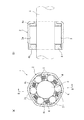
次に、本発明の好ましい実施形態について添付図面を参照しながら説明する。図1は本発明の第一の実施形態に係る一方向クラッチの断面図であり、(a)は径方向、(b)は、(a)中、B−B線矢視断面を示している。 Next, preferred embodiments of the present invention will be described with reference to the accompanying drawings. FIG. 1 is a cross-sectional view of a one-way clutch according to a first embodiment of the present invention, where (a) shows a radial direction, and (b) shows a cross section taken along line BB in (a). .
図1において、一方向クラッチ1は、回転軸Sに外嵌して用いられるものであり、回転軸Sの回転方向に応じて、当該一方向クラッチ1が固定される固定部材(図示せず)に対する回転軸Sの回転力の断続を行う。
本実施形態の一方向クラッチ1は、内輪としての回転軸Sの外周外方に配置された外輪2と、回転軸S及び外輪2の間に介在した複数のころ3と、複数のころ3を周方向に等間隔で保持している保持器4とを備えている。
In FIG. 1, a one-
The one-
外輪2は、樹脂等により形成された環状の部材であり、内周側に回転軸Sの外周面s1との間で周方向一方から他方に向けて漸次狭くなるくさび状空間Kを形成しているカム面2aが周方向に所定間隔をおいて複数形成されている。
ころ3は、金属等で形成された円筒状の部材であり、上記くさび状空間Kに配置されている。
The
The
保持器4は、樹脂等で形成された環状の部材であり、軸方向に並べて配置された第一及び第二環状部4a,4bと、周方向等間隔に形成され両環状部4a,4bを繋ぐ複数の柱部4cとを有している。周方向に互いに隣接する柱部4cの間には、ころ3を保持するための空間であるポケット5が周方向等間隔に複数形成されている。各ポケット5は、それぞれ、前記複数のくさび状空間Kに一致して設けられており、保持器4は、各ころ3がくさび状空間Kに配置されるように保持している。
The
また、一方向クラッチ1は、各くさび状空間内に配置されたころ3を当該くさび状空間における狭小方向へ付勢している複数のコイルばね6を備えている。
Further, the one-
ころ3は、コイルばね6によって狭小方向へ付勢されることで、くさび状空間K内で、回転軸Sの外周面s1と、外輪2のカム面2aとに接触している。この状態で、例えば、回転軸Sが外輪2に対して、紙面左回りに相対回転しようとすると、ころ3は、くさび状空間Kにおける狭小方向に移動しようとする。すると、外周面s1とカム面2aとの間隔は、ころ3の直径よりも漸次小さくなっているので、ころ3は、両面s1,2aの間に噛み込み、外輪2と回転軸Sとの間の相対回転が規制される。これにより、外輪2は、回転軸Sと一体に回転する。この結果、回転軸Sの回転力は、外輪2に伝達する。
The
一方、回転軸Sが外輪2に対して、紙面右回りに相対回転しようとすると、ころ3は、くさび状空間Kにおいて、外周面s1とカム面2aとの間隔が広くなる方向に移動しようとする。すると、ころ3は、両面s1,2aの間で自由状態となり、外輪2と回転軸Sとの間の相対回転が許容される。この結果、回転軸Sの回転力は、外輪2に伝達しない。
このようにして、本実施形態の一方向クラッチ1は、回転軸Sの回転方向に応じて、回転軸Sの回転力の断続を行うことができる。
On the other hand, when the rotation shaft S tries to rotate relative to the
In this way, the one-
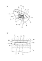
図2(a)は、図1(a)中のコイルばね6近傍を拡大した部分断面図であり、図2(b)は、図2(a)中のII−II線矢視断面図である。なお、図2(b)では、理解容易とするためにコイルばね6を破線で示している。
コイルばね6は、線材を矩形状に巻くことでその外側形状が矩形状となるように形成されており、各柱部4cに設けられた収容部7に収容されている。
コイルばね6は、収容部7に収容された状態で、ころ3及び収容部7の底面7aに当接しており、ころ3をくさび状空間K内における狭小方向へ付勢している。
2A is a partial cross-sectional view enlarging the vicinity of the
The
The
収容部7は、ポケット5の内側面5aから凹むことで有底孔状に形成されている。収容部7の内壁面の断面形状は、コイルばね6の外側形状よりも僅かに大きい矩形状に形成されている。このため、収容部7は、コイルばね6の基端側の外周を個別に収容して当該コイルばね6を支持している。また、収容部7は、コイルばね6がころ3を付勢する方向に沿って形成されており、コイルばね6の外周を包囲することで、当該コイルばね6がころ3を付勢するのをガイドしている。
The
収容部7の外周側内壁面7b及び内周側内壁面7cには、収容部7内側に向かって突出した収容部側突起8が形成されている。この収容部側突起8は、断面ほぼ三角形状で、回転軸Sの軸方向に沿って延びるように形成されている。
収容部側突起8は、底面7aの近傍に設けられており、コイルばね6の底面7aに当接している端部から一巻き目と二巻き目の線間に介在して設けられている。
収容部側突起8は、上記のようにコイルばね6の線間に介在することで、当該コイルばね6を収容部7内に係止し、コイルばね6が収容部7から抜けるのを防止している。
なお、収容部側突起8の各内壁面7b,7cに対する突出寸法は、コイルばね6の線間に介在して係止できる程度、例えば、コイルばね6の線径と同じ寸法に設定される。
On the outer peripheral side
The accommodating
The accommodating
In addition, the protrusion dimension with respect to each
コイルばね6を、その線間に収容部側突起8を介在した状態で、収容部7に収容するには、以下のように行う。すなわち、保持器4は、図2(b)に示すように、第二環状部4b及び柱部4cとが一体に形成された本体部に、第一環状部4aを取り付け固定することで構成されている。収容部7は、その側壁面7eが、第一環状部4aの端面によって構成されている。よって、保持器4の本体部に第一環状部4aを取り付ける前においては、収容部7は、この第一環状部4a側が開口している。
In order to accommodate the
コイルばね6は、保持器4の本体部に第一環状部4aを取り付ける前に、第一環状部4a側の開口から、一巻き目と二巻き目の線間に収容部側突起8を介在させつつ回転軸Sの軸方向に沿ってスライドさせて収容部7に収容する。
その後、保持器4の本体部に第一環状部4aを取り付けることで、コイルばね6は、収容部7内にその外周側が包囲された状態で収容される。
以上のようにして、コイルばね6を、その線間に収容部側突起8を介在させ、収容部7内に係止した状態で収容することができる。
Before attaching the 1st
Thereafter, by attaching the first
As described above, the
上記のように構成された一方向クラッチ1によれば、コイルばね6が収容部7から抜けるのを防止するための抜け止め手段として、収容部側突起8が収容部7に設けられているので、各収容部7それぞれにコイルばね6を収容したとしても、コイルばね6は収容部7内から抜けることがない。このため、コイルばね6を収容部7に収容するのと同時にころ3をポケット5に配置する必要がないので、コイルばね6を収容する工程と、ころ3を配置する工程とを分離することができる。よって、自動組み立て装置で当該一方向クラッチ1を組み立てる際においては、コイルばね6と、ころ3とをそれぞれ別工程でハンドリングすることが可能となり、組み立て工程を簡易とすることができる。この結果、当該一方向クラッチ1の組み立て工数を低減することができる。
また、手作業で組み立てる際においても、組み立ての途中段階でのコイルばね6の取り扱いが容易となるため、組み立て工数を低減することができる。
According to the one-
In addition, when assembling manually, the
また、収容部7の外周側内壁面7b、及び内周側内壁面7cそれぞれに、コイルばね6の線間に介在して当該コイルばね6を収容部7内に係止する収容部側突起8を設けたので、特にコイルばね6側に突起等を設けなくても、簡易に当該コイルばね6が収容部7から抜けるのを防止することができる。
In addition, the housing-
また、本実施形態では、収容部側突起8を収容部7の外周側内壁面7b、及び内周側内壁面7cそれぞれに設けたが、収容部7の側壁面7e,7fにも設け、コイルばね6の全周を係止することもできる。この場合、より確実にコイルばね6の抜け止めを行うことができる。
さらに、外周側内壁面7b、内周側内壁面7c、及び、収容部7の側壁面7e,7fの内、少なくとも一カ所に収容部側突起8を設けても良いし、少なくとも、各壁面7b〜7fの内、少なくとも、一面の一部に収容部側突起8を設けても良い。
また、本実施形態では、断面ほぼ三角形状で回転軸Sの軸方向に沿って延びる収容部側突起8としたが、この収容部側突起8の断面形状は、コイルばね6を係止することができれば、凸曲形状や、多角形状で構成されていてもよい。
Further, in the present embodiment, the housing
Further, the housing-
Further, in the present embodiment, the accommodating
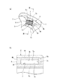
図3(a)は、本発明の第二の実施形態に係る一方向クラッチ1のコイルばね6近傍を拡大した部分断面図であり、図3(b)は、図3(a)中のIII−III線矢視断面図である。なお、図3(b)では、理解容易とするためにコイルばね6を省略して示している。
本実施形態の一方向クラッチ1は、収容部7の底面7a側に位置するコイルばね6の端部に当該コイルばね6の本体部6aの外周よりも大きく形成された拡大部6bが形成されており、収容部7の各壁面7b〜7fには、拡大部6bが嵌め込まれている溝部7gが形成されている点で、第一の実施形態と相違している。
FIG. 3 (a) is an enlarged partial cross-sectional view of the vicinity of the
In the one-
拡大部6bは、コイルばね6を構成する線材一巻き分で形成されており、矩形状である本体部6aの外周に対して、所定寸法だけ突出した矩形状となるように、各コイルばね6毎それぞれに形成されている。
溝部7gは、底面7aに沿って形成されており、拡大部6bの寸法に応じて当該拡大部6bを嵌め込み可能な寸法に設定されている。
The
The
本実施形態において、コイルばね6は、ばね側突起としての拡大部6bを、係止部としての溝部7gに嵌め込むことで当該溝部7gに係合させ、収容部7内に係止されている。
この場合、コイルばね6側に設けられた拡大部6bと、保持器4側に設けられた溝部7gとによって、より確実にコイルばね6が収容部7から抜けるのを防止することができる。
In this embodiment, the
In this case, the
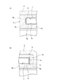
上記実施形態では、コイルばね6の端部に、線材一巻き分で形成され本体部6aの外周全周に対して突出して溝部7gに係合する拡大部6bを設けたが、例えば、図4(a)に示すように、コイルばね6の端部に、線材の先端部のみをコイルばね6の外周よりも外側方向に突出させた突起部6cをばね側突起として設けることもできる。この突起部6cを保持器4側の溝部7gに係合させることで、コイルばね6を収容部7内に係止することができる。
この場合、コイルばね6を構成する線材の先端部を外側方向に突出させるといった、簡易な方法によって溝部7gに係合するばね側突起を設けることができる。
In the above embodiment, the end portion of the
In this case, it is possible to provide a spring-side protrusion that engages with the
なお、この場合、突起部6cが突出する壁面にのみ溝部7gを設ければよく、図4(a)の場合では、突起部6cは、内周側内壁面7c側(回転軸Sの径方向内側)に突出しているので、内周側内壁面7cにのみ溝部7gを設けてもよい。
また、図4(b)に示すように、溝部7gに代えて、突起部6cが挿入される孔部7hを設けても良く、この場合、突起部6cは、第一環状部4a側(回転軸Sの軸方向に沿う方向)に突出して設けられている。孔部7hは、突起部6cが挿入されて係合できるように側壁面7eに設けられている。
また、上記突起部6cは、コイルばね6を構成する線材の先端部を本体部6aの外周よりも外側方向に突出させることで形成したが、コイルばね6の一部を本体部6aの外周よりも外側方向に突出させることで形成してもよい。
In this case, it is only necessary to provide the
Further, as shown in FIG. 4B, a
Moreover, although the said
本発明は、上記各実施形態に限定されるものではない。例えば、上記各実施形態では、外形形状が矩形状に形成されたコイルばね6を用いた場合を示したが、円形状や、三角形状等に外形形状が形成されたコイルばねを用いてもよい。
また、上記各実施形態では、外輪2と回転軸Sの外周面s1との間にころ3を介在させた構成としたが、回転軸Sの外周面に環状の内側部材を設け、外輪2と前記内側部材との間にころ3を介在させる構成としてもよい。
The present invention is not limited to the above embodiments. For example, in each of the embodiments described above, the case where the
In each of the above embodiments, the
1:一方向クラッチ 2:外輪 3:ころ 4:保持器 5:ポケット
6:コイルばね 6b:拡大部(ばね側突起) 6c:突起部(ばね側突起)
7:収容部 7g:溝部(係止部) 7h:孔部 8:収容部側突起
K:くさび状空間 S:回転軸
1: One-way clutch 2: Outer ring 3: Roller 4: Cage 5: Pocket 6:
7: accommodating
Claims (3)
前記内輪の外周外方に配置された外輪と、
前記内外輪間に形成される複数のくさび状空間にそれぞれ配置された複数のころと、
前記複数のころをそれぞれ前記複数のくさび状空間における狭小方向へ付勢する複数のコイルばねと、
前記複数のころを保持するポケット、及び、前記ポケットの内側面に設けられ前記複数のコイルばねの基端側を個別に収容して当該複数のコイルばねを支持する複数の収容部を有する保持器と、を備え、
前記保持器、及び、前記複数のコイルばねの内、少なくとも一方には、当該複数のコイルばねが前記複数の収容部から抜けるのを防止する抜け止め手段が形成されていることを特徴とする一方向クラッチ。 Inner ring,
An outer ring disposed on the outer periphery of the inner ring;
A plurality of rollers respectively disposed in a plurality of wedge-shaped spaces formed between the inner and outer rings;
A plurality of coil springs for urging each of the plurality of rollers in a narrow direction in the plurality of wedge-shaped spaces;
A holder that holds the plurality of rollers, and a holder that is provided on an inner surface of the pocket and that has a plurality of receiving portions that individually receive proximal ends of the plurality of coil springs and support the plurality of coil springs. And comprising
At least one of the retainer and the plurality of coil springs is provided with a retaining means for preventing the plurality of coil springs from coming out of the plurality of accommodating portions. Direction clutch.
前記保持器に設けられているとともに前記ばね側突起を係合させて前記複数のコイルばねを前記複数の収容部内に係止する係止部と、を含む請求項1又は2に記載の一方向クラッチ。 The retaining means includes a spring-side protrusion provided for each of the plurality of coil springs by causing a part of the wire constituting the plurality of coil springs to protrude outward from the outer periphery of the coil spring.
3. The one-way device according to claim 1, further comprising: a locking portion that is provided on the retainer and that engages the spring-side protrusion to lock the plurality of coil springs in the plurality of housing portions. clutch.
Priority Applications (1)
| Application Number | Priority Date | Filing Date | Title |
|---|---|---|---|
| JP2011029709A JP2012167752A (en) | 2011-02-15 | 2011-02-15 | One-way clutch |
Applications Claiming Priority (1)
| Application Number | Priority Date | Filing Date | Title |
|---|---|---|---|
| JP2011029709A JP2012167752A (en) | 2011-02-15 | 2011-02-15 | One-way clutch |
Publications (1)
| Publication Number | Publication Date |
|---|---|
| JP2012167752A true JP2012167752A (en) | 2012-09-06 |
Family
ID=46972099
Family Applications (1)
| Application Number | Title | Priority Date | Filing Date |
|---|---|---|---|
| JP2011029709A Pending JP2012167752A (en) | 2011-02-15 | 2011-02-15 | One-way clutch |
Country Status (1)
| Country | Link |
|---|---|
| JP (1) | JP2012167752A (en) |
Cited By (1)
| Publication number | Priority date | Publication date | Assignee | Title |
|---|---|---|---|---|
| CN113983086A (en) * | 2021-11-22 | 2022-01-28 | 人本股份有限公司 | Bicycle one-way bearing |
Citations (1)
| Publication number | Priority date | Publication date | Assignee | Title |
|---|---|---|---|---|
| JPS5972324U (en) * | 1982-11-09 | 1984-05-16 | エヌエスケー・ワーナー株式会社 | one way clutch |
-
2011
- 2011-02-15 JP JP2011029709A patent/JP2012167752A/en active Pending
Patent Citations (1)
| Publication number | Priority date | Publication date | Assignee | Title |
|---|---|---|---|---|
| JPS5972324U (en) * | 1982-11-09 | 1984-05-16 | エヌエスケー・ワーナー株式会社 | one way clutch |
Cited By (1)
| Publication number | Priority date | Publication date | Assignee | Title |
|---|---|---|---|---|
| CN113983086A (en) * | 2021-11-22 | 2022-01-28 | 人本股份有限公司 | Bicycle one-way bearing |
Similar Documents
| Publication | Publication Date | Title |
|---|---|---|
| US8302655B2 (en) | Spring drive device for a sunshade assembly | |
| JP2016021811A (en) | Motor | |
| JP2007043845A (en) | Stator structure and method for manufacturing stator | |
| CN102119285A (en) | One-way clutch retainer | |
| JP6613678B2 (en) | Thrust bearing and manufacturing method thereof | |
| CN102644665B (en) | Needle roller bearing | |
| JP2012167752A (en) | One-way clutch | |
| CN108352760B (en) | Gear motor and method for manufacturing gear motor | |
| JP4487547B2 (en) | Cage, one-way clutch using the cage, and method for assembling the one-way clutch | |
| JP2011075091A (en) | Dividable outer ring of bearing and bearing provided with dividable outer ring | |
| JP2008223995A (en) | Thrust roller bearing | |
| JP2008232279A (en) | Roller bearing | |
| JP2009275794A (en) | Thrust roller bearing | |
| JP2012180860A (en) | Bearing fixation structure | |
| JP2008312334A (en) | Brushless motor | |
| JP6025415B2 (en) | Support member and hinge device including support member | |
| JP6682416B2 (en) | One way clutch | |
| JP2011149540A (en) | Retainer assembly and one-way clutch | |
| JPH07208481A (en) | Ball bearing cage | |
| JP2015001298A (en) | Cage for thrust roller bearing and thrust roller bearing | |
| JP2015025503A (en) | Tapered roller bearing and method of manufacturing the tapered roller bearing | |
| JP6373134B2 (en) | Rotating connector device | |
| JP2000018282A (en) | One-way clutch | |
| JP6287134B2 (en) | One-way clutch | |
| JP2009185860A (en) | Rolling bearing unit |
Legal Events
| Date | Code | Title | Description |
|---|---|---|---|
| A621 | Written request for application examination |
Free format text: JAPANESE INTERMEDIATE CODE: A621 Effective date: 20140123 |
|
| A977 | Report on retrieval |
Free format text: JAPANESE INTERMEDIATE CODE: A971007 Effective date: 20140814 |
|
| A131 | Notification of reasons for refusal |
Free format text: JAPANESE INTERMEDIATE CODE: A131 Effective date: 20140819 |
|
| A02 | Decision of refusal |
Free format text: JAPANESE INTERMEDIATE CODE: A02 Effective date: 20141216 |