JP2012167693A - Power transmission device - Google Patents
Power transmission device Download PDFInfo
- Publication number
- JP2012167693A JP2012167693A JP2011026917A JP2011026917A JP2012167693A JP 2012167693 A JP2012167693 A JP 2012167693A JP 2011026917 A JP2011026917 A JP 2011026917A JP 2011026917 A JP2011026917 A JP 2011026917A JP 2012167693 A JP2012167693 A JP 2012167693A
- Authority
- JP
- Japan
- Prior art keywords
- pulse rotor
- transmission device
- power transmission
- rotating member
- seal member
- Prior art date
- Legal status (The legal status is an assumption and is not a legal conclusion. Google has not performed a legal analysis and makes no representation as to the accuracy of the status listed.)
- Withdrawn
Links
Images
Landscapes
- General Details Of Gearings (AREA)
Abstract
【課題】パルスロータに隣接配置されたシール部材の潤滑性を向上することができる動力伝達装置を提供する。
【解決手段】潤滑油が収容されたケーシング3と、このケーシング3に回転可能に収容支持された回転部材5と、この回転部材5と一体回転可能に設けられ回転部材5の回転を検出するパルスロータ7と、このパルスロータ7に隣接配置されケーシング3と回転部材5との間をシールするシール部材9とを備えた動力伝達装置1において、パルスロータ7に、パルスロータ7の外径側から流入される潤滑油をパルスロータ7の回転によってシール部材9に導入させる導入手段11を設けた。
【選択図】図2A power transmission device capable of improving the lubricity of a seal member disposed adjacent to a pulse rotor is provided.
A casing 3 that contains lubricating oil, a rotating member 5 that is rotatably accommodated and supported by the casing 3, and a pulse that is provided so as to rotate integrally with the rotating member 5 and detects the rotation of the rotating member 5. In the power transmission device 1 that includes the rotor 7 and the seal member 9 that is disposed adjacent to the pulse rotor 7 and seals between the casing 3 and the rotating member 5, the pulse rotor 7 is connected to the pulse rotor 7 from the outer diameter side. Introducing means 11 for introducing the lubricating oil introduced into the sealing member 9 by the rotation of the pulse rotor 7 is provided.
[Selection] Figure 2
Description
本発明は、車両に適用される動力伝達装置に関する。 The present invention relates to a power transmission device applied to a vehicle.
従来、動力伝達装置としては、潤滑油が収容されたケーシングと、このケーシングに回転可能に収容支持された回転部材としての後輪出力軸と、この後輪出力軸と一体回転可能に設けられ後輪出力軸の回転を検出するパルスロータとしてのメータギヤとを備えたものが知られている(例えば、特許文献1参照)。 Conventionally, as a power transmission device, a casing in which lubricating oil is accommodated, a rear wheel output shaft as a rotating member that is rotatably accommodated and supported by the casing, and a rear wheel output shaft that is integrally rotatable with the rear wheel output shaft are provided. A device including a meter gear as a pulse rotor that detects rotation of a wheel output shaft is known (see, for example, Patent Document 1).
この動力伝達装置では、メータギヤの回転、すなわち後輪出力軸の回転がウォームギヤを介してケーシングの外部に設けられた車速センサによって検出される。このような回転部材と一体回転するメータギヤは、ケーシングと後輪出力軸との間をシールするシール部材に対して隣接配置されている。 In this power transmission device, rotation of the meter gear, that is, rotation of the rear wheel output shaft, is detected by a vehicle speed sensor provided outside the casing via the worm gear. The meter gear that rotates integrally with the rotating member is disposed adjacent to the sealing member that seals between the casing and the rear wheel output shaft.
しかしながら、上記のような動力伝達装置では、シール部材に隣接配置されたパルスロータが回転部材と一体回転するので、パルスロータの回転によって潤滑油が飛散されてしまい、シール部材に潤滑油を十分に供給させることが困難であった。 However, in the power transmission device as described above, since the pulse rotor disposed adjacent to the seal member rotates integrally with the rotating member, the lubricant is scattered by the rotation of the pulse rotor, and the lubricant is sufficiently supplied to the seal member. It was difficult to supply.
このため、回転部材と摺動するシール部材の摺動部の潤滑が不十分となり、シール部材の耐久性が低下する可能性があった。 For this reason, lubrication of the sliding portion of the seal member that slides with the rotating member becomes insufficient, and the durability of the seal member may be reduced.
そこで、この発明は、パルスロータに隣接配置されたシール部材の潤滑性を向上することができる動力伝達装置の提供を目的としている。 Therefore, an object of the present invention is to provide a power transmission device that can improve the lubricity of a seal member disposed adjacent to a pulse rotor.
本発明は、潤滑油が収容されたケーシングと、このケーシングに回転可能に収容支持された回転部材と、この回転部材と一体回転可能に設けられ前記回転部材の回転を検出するパルスロータと、このパルスロータに隣接配置され前記ケーシングと前記回転部材との間をシールするシール部材とを備えた動力伝達装置であって、前記パルスロータと前記ケーシングとのうち少なくとも一方には、前記パルスロータの外径側から流入される前記潤滑油を前記パルスロータの回転によって前記シール部材に導入させる導入手段が設けられていることを特徴とする。 The present invention includes a casing in which lubricating oil is accommodated, a rotating member that is rotatably accommodated and supported in the casing, a pulse rotor that is provided so as to be rotatable integrally with the rotating member and detects the rotation of the rotating member, A power transmission device comprising a seal member disposed adjacent to a pulse rotor and sealing between the casing and the rotating member, wherein at least one of the pulse rotor and the casing is provided outside the pulse rotor. Introducing means for introducing the lubricating oil flowing in from the diameter side into the seal member by rotation of the pulse rotor is provided.
この動力伝達装置では、パルスロータとケーシングとのうち少なくとも一方にパルスロータの外径側から流入される潤滑油をパルスロータの回転によってシール部材に導入させる導入手段が設けられているので、パルスロータの回転によって潤滑油が飛散することがなく、シール部材に潤滑油を十分に供給させることができ、シール部材の耐久性を向上することができる。 In this power transmission device, at least one of the pulse rotor and the casing is provided with introduction means for introducing the lubricating oil flowing from the outer diameter side of the pulse rotor into the seal member by rotation of the pulse rotor. As a result of the rotation, the lubricating oil does not scatter, the lubricating oil can be sufficiently supplied to the sealing member, and the durability of the sealing member can be improved.
従って、このような動力伝達装置では、パルスロータに隣接配置されたシール部材の潤滑性を向上することができる。 Therefore, in such a power transmission device, the lubricity of the seal member disposed adjacent to the pulse rotor can be improved.
本発明によれば、パルスロータに隣接配置されたシール部材の潤滑性を向上することができる動力伝達装置を提供することができるという効果を奏する。 According to the present invention, there is an effect that it is possible to provide a power transmission device that can improve the lubricity of the seal member disposed adjacent to the pulse rotor.
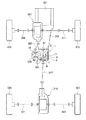
まず、図1を用いて本発明の実施の形態に係る動力伝達装置が適用される車両の動力系の一例について説明する。なお、ここでは、第1実施形態に係る動力伝達装置1を適用した動力系とするが、他の実施形態に係る動力伝達装置も第1実施形態の動力伝達装置1と同様に適用することができる。
First, an example of a vehicle power system to which a power transmission device according to an embodiment of the present invention is applied will be described with reference to FIG. In addition, although it is set as the power system which applied the
図1に示すように、車両の動力系は、エンジンや電動モータなどの駆動源301と、変速機構としてのトランスミッション303と、動力伝達装置1と、前輪側プロペラシャフト305と、前輪側の左右輪の差動を許容するフロントデフ307と、前車軸309,311と、前輪313,315と、後輪側プロペラシャフト317と、後輪側の左右輪の差動を許容するリヤデフ319と、後車軸321,323と、後輪325,327などから構成されている。
As shown in FIG. 1, the power system of the vehicle includes a
駆動源301の駆動力は、トランスミッション303から動力伝達装置1の回転部材5に常時伝達される。この回転部材5に伝達された駆動力は、後輪側プロペラシャフト317を介してリヤデフ319に伝達され、後車軸321,323から後輪325,327に配分される。また、回転部材5に伝達された駆動力は、カップリング17を介してスプロケット15に伝達される。このスプロケット15に伝達された駆動力は、チェーン機構329を介して前輪側プロペラシャフト305に伝達され、フロントデフ307を介して前車軸309,311から前輪313,315に配分される。
The driving force of the
このような動力系に配置された動力伝達装置1は、回転部材5と一体回転可能にパルスロータ7が設けられ、このパルスロータ7の回転を検出手段としてのセンサ331によって検出している。このパルスロータ7には、ケーシング3と回転部材5との間をシールするシール部材9が隣接配置されている。以下、図2〜図4を用いて本発明の実施の形態に係る動力伝達装置について説明する。
In the
なお、以下に記載のパルスロータ7は、プレート部材をプレス屈曲形成し、環状部分に凹凸形状の歯部を形成し、電流ピックアップ式の変動起電力をパルス信号として検出するために設けられた形状を用いている。しかしながら、他の形状のパルスロータと検出手段としてのセンサを用いることもできる。
The
(第1実施形態)
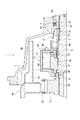
図2を用いて第1実施形態について説明する。
(First embodiment)
The first embodiment will be described with reference to FIG.
本実施の形態に係る動力伝達装置1は、潤滑油が収容されたケーシング3と、このケーシング3に回転可能に収容支持された回転部材5と、この回転部材5と一体回転可能に設けられ回転部材5の回転を検出するパルスロータ7と、このパルスロータ7に隣接配置されケーシング3と回転部材5との間をシールするシール部材9とを備えている。
The
そして、パルスロータ7には、パルスロータ7の外径側から流入される潤滑油をパルスロータ7の回転によってシール部材9に導入させる導入手段11が設けられている。
The
また、導入手段11は、シール部材9に向けて下り傾斜となる傾斜部13を有する。
Further, the introducing means 11 has an
図2に示すように、動力伝達装置1は、ケーシング3と、スプロケット15と、カップリング17と、回転部材5と、パルスロータ7と、シール部材9などから構成されている。
As shown in FIG. 2, the
ケーシング3は、車体フレームやトランスミッション303(図1参照)を収容するケースなどの静止系部材に固定される。このケーシング3内には、収容される部材の摺動部などを潤滑・冷却させる潤滑油が収容され、この潤滑油はケーシング3内に配置されたオイルガータ19によってケーシング3内を循環される。
The
オイルガータ19は、油溜まり21と、油路23とを備えている。このオイルガータ19は、スプロケット15の回転によって掻き上げられた潤滑油を油溜まり21に貯留させ、油路23を流通させて端部から吐出し、パルスロータ7の外径側に潤滑油を供給させる。このようなオイルガータ19が配置されたケーシング3内には、スプロケット15と、カップリング17と、回転部材5と、パルスロータ7と、シール部材9などが収容されている。
The
スプロケット15は、内径側が回転部材5の外周上にニードルベアリング25を介して回転部材5と相対回転可能に配置されている。このスプロケット15の外径側には、チェーン機構329(図1参照)を構成するチェーン27が配置されており、チェーン機構329を介してフロントデフ307(図1参照)側に駆動力を出力する。このようなスプロケット15は、カップリング17を介して駆動力が入力される。
The
カップリング17は、外側回転部材29と、内側回転部材31と、複数の抵抗板と、粘性流体とからなる。外側回転部材29は、円筒状に形成され、回転部材5の外周上に配置されている。この外側回転部材29は、スプライン形状の連結部33を介してスプロケット15と一体回転可能に連結されている。
The
内側回転部材31は、外側回転部材29を閉塞するように外側回転部材29の内径側に配置され、摺動部材及びシール手段としてのXリング35,37を介して外側回転部材29と相対回転可能に回転部材5の外周上に配置されている。この内側回転部材31は、スプライン形状の連結部39を介して回転部材5と一体回転可能に連結されている。
The inner rotating
複数の抵抗板は、外側抵抗板と内側抵抗板とからなる。複数の外側抵抗板は、外側回転部材の内径に形成されたスプライン形状の係合部41に軸方向移動可能で外側回転部材29と一体回転可能に係合されている。複数の内側抵抗板は、複数の外側抵抗板に対して軸方向に交互に配置され、内側回転部材31の外径に形成されたスプライン形状の係合部43に軸方向移動可能で内側回転部材31と一体回転可能に連結されている。
The plurality of resistance plates include an outer resistance plate and an inner resistance plate. The plurality of outer resistance plates are engaged with a spline-
粘性流体は、シリコンオイルなどからなり、外側回転部材29と内側回転部材31とXリング35,37とで形成された密封空間45内に封入される。この粘性流体は、複数の抵抗板に粘性流体をせん断するせん断抵抗を生じさせ、この抵抗によって外側回転部材29と内側回転部材31との間、すなわちスプロケット15と回転部材5との間の動力伝達が可能となる。
The viscous fluid is made of silicon oil or the like, and is enclosed in a sealed
回転部材5は、ベアリング47(図1参照)とベアリング49とを介してケーシング3に回転可能に支持されている。また、回転部材5は、軸方向の一側がトランスミッション303(図1参照)側に連結され、軸方向の他側に後輪側プロペラシャフト317(図1参照)に連結される連結部材51がスプライン形状の連結部53を介して一体回転可能に連結されている。この回転部材5は、駆動源301側(図1参照)からの駆動力が常時伝達されており、連結部材51を介してリヤデフ319(図1参照)側に駆動力を出力すると共に、カップリング17を介してフロントデフ307(図1参照)側に駆動力を出力する。このような回転部材5には、パルスロータ7が一体回転可能に連結されている。
The rotating
なお、ここでは、回転部材5側からカップリング17を介してスプロケット15側に駆動力を出力する構成としているが、スプロケット15側からカップリング17を介して回転部材5側に駆動力を出力する構成としてもよい。この場合には、フロントデフ307に駆動源301からの駆動力が常時伝達される構成となるので、フロントデフ307に駆動力を入力させる回転部材にパルスロータ7を一体回転可能に設ければよい。
Here, the driving force is output from the rotating
パルスロータ7は、固定部55と、検出部57とを備えている。固定部55は、筒状に形成されて内周がスプライン形状に形成され、回転部材5の連結部53に一体回転可能に連結される。検出部57は、固定部55の外径側に固定部55と一体に設けられ、固定部55の周方向等間隔に複数設けられている。この検出部57の回転をセンサ331(図1参照)によって検出することにより、回転部材5の回転を検出することができる。このパルスロータ7には、シール部材9が隣接配置されている。
The
シール部材9は、回転部材5と一体回転する連結部材51とケーシング3との径方向間に配置され、ケーシング3の内部と外部とを区画している。このシール部材9の内径側は、連結部材51と摺動してシールするリップ部59となっている。このリップ部59には、オイルガータ19からパルスロータ7の外径側に位置する検出部57に供給された潤滑油が検出部57とケーシング3との間を流入して供給されることになるが、パルスロータ7の回転によって潤滑油がリップ部59に十分に供給されない可能性がある。そこで、パルスロータ7には、シール部材9側に潤滑油を導入させる導入手段11が設けられている。
The
導入手段11は、複数の検出部57をシール部材9に向けて下り傾斜となるように傾斜させた傾斜部13となっている。この傾斜部13を設けることにより、検出部57とケーシング3との間を広くさせることでき、潤滑油を導入し易くすることができる。また、この傾斜部13は、シール部材9に向けて下り傾斜となっているので、パルスロータ7の回転によってベアリング49側に潤滑油が飛散することを抑制できると共に、シール部材9側への潤滑油の流入をパルスロータ7の回転によって促進させることができる。このような導入手段11により、シール部材9側に潤滑油を十分に供給することができ、シール部材9のリップ部59の損傷を防止してシール部材9の耐久性を向上することができる。
The introducing means 11 is an
このような動力伝達装置1では、パルスロータ7にパルスロータ7の外径側から流入される潤滑油をパルスロータ7の回転によってシール部材9に導入させる導入手段11が設けられているので、パルスロータ7の回転によって潤滑油が飛散することがなく、シール部材9に潤滑油を十分に供給させることができ、シール部材9の耐久性を向上することができる。
In such a
従って、このような動力伝達装置1では、パルスロータ7に隣接配置されたシール部材9の潤滑性を向上することができる。
Therefore, in such a
また、導入手段11は、シール部材9に向けて下り傾斜となる傾斜部13を有するので、パルスロータ7の外径側とケーシング3との間を広くすることができ、シール部材9側に潤滑油を導入し易くすることができる。加えて、シール部材9側への潤滑油の流入をパルスロータ7の回転によって促進させることができる。
Further, since the introducing means 11 has the inclined
(第2実施形態)
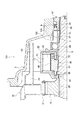
図3を用いて第2実施形態について説明する。
(Second Embodiment)
A second embodiment will be described with reference to FIG.
本実施の形態に係る動力伝達装置101は、導入手段103は、パルスロータ7の外径に設けられパルスロータ7の回転によって潤滑油をシール部材9側に吸引する複数の羽根部105を有する。なお、第1実施形態と同一の構成には、同一の記号を記して説明を省略するが、第1実施形態と同一の構成であるので、構成及び機能説明は第1実施形態を参照するものとし省略するが、得られる効果は同一である。
In the
図3に示すように、導入手段103は、複数の検出部57のベアリング49側の端部に設けられた複数の羽根部105となっている。この複数の羽根部105は、パルスロータ7の回転によって潤滑油がシール部材9側に吸引されるように設定されている。このため、パルスロータ7が回転することにより、検出部57側に流入される潤滑油が飛散されずに複数の羽根部105によって吸引され、シール部材9側に潤滑油を供給することができる。このような導入手段103により、シール部材9側に潤滑油を十分に供給することができ、シール部材9のリップ部59の損傷を防止してシール部材9の耐久性を向上することができる。
As shown in FIG. 3, the
このような動力伝達装置101では、導入手段103がパルスロータ7の外径に設けられパルスロータ7の回転によって潤滑油をシール部材9側に吸引する複数の羽根部105を有するので、パルスロータ7の外径側に流入される潤滑油が飛散されずに複数の羽根部105によって吸引することができ、シール部材9側に潤滑油を十分に供給することができる。
In such a
(第3実施形態)
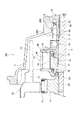
図4を用いて第3実施形態について説明する。
(Third embodiment)
A third embodiment will be described with reference to FIG.
本実施の形態に係る動力伝達装置201は、導入手段203は、ケーシング3のパルスロータ7と径方向に対向する対向面に設けられパルスロータ7の回転によって潤滑油をシール部材9側に流入させる螺旋溝205を有する。なお、第1実施形態と同一の構成には、同一の記号を記して説明を省略するが、第1実施形態と同一の構成であるので、構成及び機能説明は第1実施形態を参照するものとし省略するが、得られる効果は同一である。
In the
図4に示すように、導入手段203は、パルスロータ7の検出部57と径方向に対向するケーシング3の対向面に設けられた螺旋溝205となっている。この螺旋溝205は、パルスロータ7の回転によって潤滑油をシール部材9側に流入させるようなオイルポンプ機能を有するように設定されている。このため、パルスロータ7が回転することにより、検出部57側に流入される潤滑油が螺旋溝205に流入され、シール部材9側に潤滑油を供給することができる。このような導入手段203により、シール部材9側に潤滑油を十分に供給することができ、シール部材9のリップ部59の損傷を防止してシール部材9の耐久性を向上することができる。
As shown in FIG. 4, the introduction means 203 is a
このような動力伝達装置201では、導入手段203は、ケーシング3のパルスロータ7と径方向に対向する対向面に設けられパルスロータ7の回転によって潤滑油をシール部材9側に流入させる螺旋溝205を有するので、パルスロータ7の外径側に流入される潤滑油をパルスロータ7の回転によるオイルポンプ機能によって螺旋溝205内を流通させることができ、シール部材9側に潤滑油を十分に供給することができる。
In such a
なお、本発明の実施の形態に係る動力伝達装置では、導入手段が傾斜部と複数の羽根部と螺旋溝となっているが、これに限らず、例えば、パルスロータの検出部に検出部をねじるようなねじり角を与える構造やケーシングにパルスロータの回転によって飛散する潤滑油を収集する構造など、パルスロータの回転によってシール部材側に潤滑油を導入できる構造であれば導入手段はどのような形態であってもよい。 In the power transmission device according to the embodiment of the present invention, the introduction means is an inclined portion, a plurality of blade portions, and a spiral groove. However, the present invention is not limited to this, and for example, a detection portion is provided in the detection portion of the pulse rotor. What is the introduction means as long as it is a structure that can introduce the lubricating oil to the seal member by the rotation of the pulse rotor, such as a structure that gives a twisting angle that twists and a structure that collects the lubricating oil scattered by the rotation of the pulse rotor in the casing? Form may be sufficient.
また、各実施形態では、傾斜部と複数の羽根部と螺旋溝とがそれぞれ独立して設けられた構成となっているが、例えば、傾斜部と螺旋溝とを合わせた構成、傾斜部と複数の羽根部とを合わせた構成、もしくは全てを合わせた構成などシール部材側への潤滑油の導入が促進される構成であれば導入手段はどのような組合せであってもよい。 In each embodiment, the inclined portion, the plurality of blade portions, and the spiral groove are provided independently. For example, the inclined portion and the spiral groove are combined. The introduction means may be in any combination as long as the introduction of the lubricating oil to the seal member side is promoted, such as a configuration in which the blade portions are combined or a configuration in which all the blade portions are combined.
1,101,201…動力伝達装置
3…ケーシング
5…回転部材
7…パルスロータ
9…シール部材
11,103,203…導入手段
13…傾斜部
105…羽根部
205…螺旋溝
DESCRIPTION OF SYMBOLS 1,101,201 ...
Claims (4)
前記パルスロータと前記ケーシングとのうち少なくとも一方には、前記パルスロータの外径側から流入される前記潤滑油を前記パルスロータの回転によって前記シール部材に導入させる導入手段が設けられていることを特徴とする動力伝達装置。 A casing in which lubricating oil is accommodated, a rotating member that is rotatably accommodated and supported in the casing, a pulse rotor that is provided so as to rotate integrally with the rotating member and detects the rotation of the rotating member, and adjacent to the pulse rotor A power transmission device comprising a seal member disposed and sealing between the casing and the rotating member,
At least one of the pulse rotor and the casing is provided with introducing means for introducing the lubricating oil flowing from the outer diameter side of the pulse rotor into the seal member by rotation of the pulse rotor. A power transmission device.
前記導入手段は、前記パルスロータの外径に設けられ前記シール部材に向けて下り傾斜となる傾斜部を有することを特徴とする動力伝達装置。 The power transmission device according to claim 1,
The power transmission device according to claim 1, wherein the introduction unit includes an inclined portion that is provided on an outer diameter of the pulse rotor and is inclined downward toward the seal member.
前記導入手段は、前記パルスロータの外径に設けられ前記パルスロータの回転によって前記潤滑油を前記シール部材側に吸引する複数の羽根部を有することを特徴とする動力伝達装置。 The power transmission device according to claim 1 or 2,
The power transmission device according to claim 1, wherein the introduction unit includes a plurality of blade portions that are provided on an outer diameter of the pulse rotor and suck the lubricating oil toward the seal member by rotation of the pulse rotor.
前記導入手段は、前記ケーシングの前記パルスロータと径方向に対向する対向面に設けられ前記パルスロータの回転によって前記潤滑油を前記シール部材側に流入させる螺旋溝を有することを特徴とする動力伝達装置。 The power transmission device according to any one of claims 1 to 3,
The introduction means includes a spiral groove that is provided on a surface of the casing that is opposed to the pulse rotor in a radial direction and that allows the lubricating oil to flow into the seal member by rotation of the pulse rotor. apparatus.
Priority Applications (1)
| Application Number | Priority Date | Filing Date | Title |
|---|---|---|---|
| JP2011026917A JP2012167693A (en) | 2011-02-10 | 2011-02-10 | Power transmission device |
Applications Claiming Priority (1)
| Application Number | Priority Date | Filing Date | Title |
|---|---|---|---|
| JP2011026917A JP2012167693A (en) | 2011-02-10 | 2011-02-10 | Power transmission device |
Publications (1)
| Publication Number | Publication Date |
|---|---|
| JP2012167693A true JP2012167693A (en) | 2012-09-06 |
Family
ID=46972044
Family Applications (1)
| Application Number | Title | Priority Date | Filing Date |
|---|---|---|---|
| JP2011026917A Withdrawn JP2012167693A (en) | 2011-02-10 | 2011-02-10 | Power transmission device |
Country Status (1)
| Country | Link |
|---|---|
| JP (1) | JP2012167693A (en) |
-
2011
- 2011-02-10 JP JP2011026917A patent/JP2012167693A/en not_active Withdrawn
Similar Documents
| Publication | Publication Date | Title |
|---|---|---|
| CN107208778B (en) | electric drive | |
| JP5817247B2 (en) | Motor rotational force transmission device | |
| JP5297758B2 (en) | In-wheel motor drive device | |
| CN107791823B (en) | In-wheel motor unit | |
| JP4930453B2 (en) | Bearing lubrication structure of rotating shaft | |
| JP6265184B2 (en) | Power transmission device | |
| JP4610227B2 (en) | Power transmission device compartment structure | |
| CN106464087A (en) | In-wheel motor drive device | |
| CN111750045B (en) | Planetary reduction device, drive axle assembly and vehicle | |
| EP3003760B1 (en) | Electric drive device for driving a motor vehicle | |
| JP5811335B2 (en) | Bearing device, reduction mechanism provided with the same, and motor torque transmission device | |
| CN108700177B (en) | Drive device | |
| CN108204446A (en) | Power plant | |
| JP2013007443A (en) | Speed reduction mechanism and motor rotation force transmission device equipped with the same | |
| CN112555387A (en) | Drive device for vehicle | |
| CN109421499B (en) | Vehicle drive device | |
| JP2015027820A (en) | In-wheel motor driving device | |
| CN106240356A (en) | Bevel gear wheel connector assembly | |
| JP4701587B2 (en) | Electric drive | |
| JP5806133B2 (en) | In-wheel motor drive device | |
| JP2016065617A (en) | Lubricating device for in-wheel motor drive | |
| JP2015116900A (en) | Wheel drive device | |
| JP2013147217A (en) | In-wheel motor driving device | |
| JP2014190374A (en) | Differential device | |
| JP2012167693A (en) | Power transmission device |
Legal Events
| Date | Code | Title | Description |
|---|---|---|---|
| A300 | Withdrawal of application because of no request for examination |
Free format text: JAPANESE INTERMEDIATE CODE: A300 Effective date: 20140513 |