JP2012166375A - Inkjet printing apparatus and recovery method for print head thereof - Google Patents
Inkjet printing apparatus and recovery method for print head thereof Download PDFInfo
- Publication number
- JP2012166375A JP2012166375A JP2011027196A JP2011027196A JP2012166375A JP 2012166375 A JP2012166375 A JP 2012166375A JP 2011027196 A JP2011027196 A JP 2011027196A JP 2011027196 A JP2011027196 A JP 2011027196A JP 2012166375 A JP2012166375 A JP 2012166375A
- Authority
- JP
- Japan
- Prior art keywords
- recording
- nozzle
- nozzles
- ink
- preliminary ejection
- Prior art date
- Legal status (The legal status is an assumption and is not a legal conclusion. Google has not performed a legal analysis and makes no representation as to the accuracy of the status listed.)
- Granted
Links
Images


Classifications
-
- B—PERFORMING OPERATIONS; TRANSPORTING
- B41—PRINTING; LINING MACHINES; TYPEWRITERS; STAMPS
- B41J—TYPEWRITERS; SELECTIVE PRINTING MECHANISMS, i.e. MECHANISMS PRINTING OTHERWISE THAN FROM A FORME; CORRECTION OF TYPOGRAPHICAL ERRORS
- B41J2/00—Typewriters or selective printing mechanisms characterised by the printing or marking process for which they are designed
- B41J2/005—Typewriters or selective printing mechanisms characterised by the printing or marking process for which they are designed characterised by bringing liquid or particles selectively into contact with a printing material
- B41J2/01—Ink jet
- B41J2/135—Nozzles
- B41J2/165—Prevention or detection of nozzle clogging, e.g. cleaning, capping or moistening for nozzles
- B41J2/16517—Cleaning of print head nozzles
- B41J2/1652—Cleaning of print head nozzles by driving a fluid through the nozzles to the outside thereof, e.g. by applying pressure to the inside or vacuum at the outside of the print head
- B41J2/16526—Cleaning of print head nozzles by driving a fluid through the nozzles to the outside thereof, e.g. by applying pressure to the inside or vacuum at the outside of the print head by applying pressure only
-
- B—PERFORMING OPERATIONS; TRANSPORTING
- B41—PRINTING; LINING MACHINES; TYPEWRITERS; STAMPS
- B41J—TYPEWRITERS; SELECTIVE PRINTING MECHANISMS, i.e. MECHANISMS PRINTING OTHERWISE THAN FROM A FORME; CORRECTION OF TYPOGRAPHICAL ERRORS
- B41J2/00—Typewriters or selective printing mechanisms characterised by the printing or marking process for which they are designed
- B41J2/005—Typewriters or selective printing mechanisms characterised by the printing or marking process for which they are designed characterised by bringing liquid or particles selectively into contact with a printing material
- B41J2/01—Ink jet
- B41J2/135—Nozzles
- B41J2/165—Prevention or detection of nozzle clogging, e.g. cleaning, capping or moistening for nozzles
- B41J2/16517—Cleaning of print head nozzles
- B41J2/16535—Cleaning of print head nozzles using wiping constructions
- B41J2/16544—Constructions for the positioning of wipers
- B41J2/16547—Constructions for the positioning of wipers the wipers and caps or spittoons being on the same movable support
-
- B—PERFORMING OPERATIONS; TRANSPORTING
- B41—PRINTING; LINING MACHINES; TYPEWRITERS; STAMPS
- B41J—TYPEWRITERS; SELECTIVE PRINTING MECHANISMS, i.e. MECHANISMS PRINTING OTHERWISE THAN FROM A FORME; CORRECTION OF TYPOGRAPHICAL ERRORS
- B41J2/00—Typewriters or selective printing mechanisms characterised by the printing or marking process for which they are designed
- B41J2/005—Typewriters or selective printing mechanisms characterised by the printing or marking process for which they are designed characterised by bringing liquid or particles selectively into contact with a printing material
- B41J2/01—Ink jet
- B41J2/135—Nozzles
- B41J2/165—Prevention or detection of nozzle clogging, e.g. cleaning, capping or moistening for nozzles
- B41J2/16585—Prevention or detection of nozzle clogging, e.g. cleaning, capping or moistening for nozzles for paper-width or non-reciprocating print heads
-
- B—PERFORMING OPERATIONS; TRANSPORTING
- B41—PRINTING; LINING MACHINES; TYPEWRITERS; STAMPS
- B41J—TYPEWRITERS; SELECTIVE PRINTING MECHANISMS, i.e. MECHANISMS PRINTING OTHERWISE THAN FROM A FORME; CORRECTION OF TYPOGRAPHICAL ERRORS
- B41J2/00—Typewriters or selective printing mechanisms characterised by the printing or marking process for which they are designed
- B41J2/005—Typewriters or selective printing mechanisms characterised by the printing or marking process for which they are designed characterised by bringing liquid or particles selectively into contact with a printing material
- B41J2/01—Ink jet
- B41J2/135—Nozzles
- B41J2/165—Prevention or detection of nozzle clogging, e.g. cleaning, capping or moistening for nozzles
- B41J2/16517—Cleaning of print head nozzles
- B41J2002/1657—Cleaning of only nozzles or print head parts being selected
Landscapes
- Ink Jet (AREA)
Abstract
【課題】ライン型の長尺な記録ヘッドの回復処理時の廃インク量を抑制できるインクジェット記録装置を提供する。
【解決手段】画像記録に使用する使用ノズルの数および位置に応じて規定される複数の記録モードのうち、設定されている記録モードを特定し、記録媒体への画像の記録の前又は後において、前記複数のノズルのうち、設定されている記録モードにおける使用ノズルおよび当該使用ノズルの近傍の不使用ノズルから選択的にインクを予備吐出させる第1の予備吐出処理を実行する。
【選択図】図10An inkjet recording apparatus capable of suppressing the amount of waste ink at the time of recovery processing of a line-type long recording head.
Among a plurality of recording modes defined according to the number and positions of nozzles used for image recording, a set recording mode is specified, and before or after recording an image on a recording medium. A first preliminary ejection process is performed in which ink is selectively preliminarily ejected from the used nozzle in the set recording mode and the unused nozzle in the vicinity of the used nozzle among the plurality of nozzles.
[Selection] Figure 10
Description
本発明は、インクジェット記録装置およびインクジェット記録装置の記録ヘッドよりインクを吐出させてインク吐出性能を回復させる回復処理方法に関する。 The present invention relates to an inkjet recording apparatus and a recovery processing method for recovering ink ejection performance by ejecting ink from a recording head of the inkjet recording apparatus.
特許文献1は、印刷終了時点からタイマーを起動させてその経過時間を監視し、この経過時間が所定時間を超えているか否かを判断して、印刷吐出パターンに基づいて予備吐出パターンを作成し、予備吐出回復処理を実行する技術を開示する。これにより、常に全ノズルから一定量のインク滴の予備吐出を行うのではなく、全ノズルの予備吐出か、非吐出ノズルのみの予備吐出かを設定して、回復処理に使用するインク液の消費量を抑制する。 Patent Document 1 starts a timer from the end of printing, monitors the elapsed time, determines whether the elapsed time exceeds a predetermined time, and creates a preliminary discharge pattern based on the print discharge pattern. A technique for executing the preliminary discharge recovery process is disclosed. As a result, instead of always performing a preliminary discharge of a fixed amount of ink droplets from all nozzles, it is possible to set the preliminary discharge of all nozzles or only the non-discharge nozzles to consume ink used for recovery processing. Reduce the amount.
ところで、いわゆるライン型記録ヘッドとして、複数のノズルチップを千鳥配列のように規則的に配置したものが知られている。このような長尺なライン型記録ヘッドに対して、特許文献1に開示された予備吐出回復処理を適用すると、無駄なインク消費が増加するという問題が生じる。具体的には、記録媒体の紙幅が狭い記録媒体への記録を記録終了から所定時間を超えた間隔で連続的に行う場合、特許文献1の予備吐出回復処理を実行させると、記録に使用されない記録媒体の幅を超えた領域の不使用ノズルも含めて予備吐出を常に実行してしまう。 By the way, what is known as a so-called line type recording head is one in which a plurality of nozzle chips are regularly arranged in a staggered arrangement. When the preliminary ejection recovery process disclosed in Patent Document 1 is applied to such a long line type recording head, there arises a problem that wasteful ink consumption increases. Specifically, when recording on a recording medium having a narrow paper width is continuously performed at intervals exceeding a predetermined time from the end of recording, the preliminary ejection recovery process of Patent Document 1 is not used for recording. Preliminary ejection is always performed, including unused nozzles in areas beyond the width of the recording medium.
本発明は上述の技術的課題に鑑みてなされたものである。その目的とするところは、回復処理時のインクの消費量を最小化できるインクジェット記録装置及びその回復処理方法を提供することにある。 The present invention has been made in view of the above technical problems. An object of the present invention is to provide an ink jet recording apparatus capable of minimizing ink consumption during the recovery process and a recovery process method thereof.
本発明のインクジェット記録装置は、複数のノズルが配列された記録ヘッドと、前記複数のノズルのインク吐出性能を回復させるために、前記複数のノズルからインクを予備吐出させる予備吐出制御手段と、を有するインクジェット記録装置であって、画像記録に使用する使用ノズルの数および位置に応じて規定される複数の記録モードのうち、設定されている記録モードを特定する手段を有し、前記予備吐出制御手段は、記録媒体への画像の記録の前又は後において、前記複数のノズルのうち、設定されている記録モードにおける使用ノズルおよび当該使用ノズルの近傍の不使用ノズルから選択的にインクを予備吐出させる第1の予備吐出処理を実行する、ことを特徴とする。 The inkjet recording apparatus of the present invention includes a recording head in which a plurality of nozzles are arranged, and preliminary ejection control means for preliminary ejecting ink from the plurality of nozzles in order to recover the ink ejection performance of the plurality of nozzles. An ink jet recording apparatus comprising: means for specifying a set recording mode among a plurality of recording modes defined according to the number and positions of nozzles used for image recording, and the preliminary ejection control The means pre-discharges ink selectively from the use nozzle in the set print mode and the non-use nozzle in the vicinity of the use nozzle among the plurality of nozzles before or after the image is recorded on the print medium. The first preliminary discharge process is executed.
また、本発明は、前記記録モードが変更されたかを検出する手段をさらに有し、前記予備吐出制御手段は、前記記録モードの変更が検出された場合には、記録媒体への画像の記録前において、不使用ノズルから新たに使用ノズルとなったノズルおよび当該新たに使用ノズルとなったノズルの近傍の不使用ノズルから選択的にインクを予備吐出させる第2の予備吐出処理を実行する、構成を採用できる。 The present invention further includes means for detecting whether or not the recording mode has been changed, and the preliminary ejection control means can detect whether the recording mode has been changed before recording an image on a recording medium. A second preliminary ejection process for selectively preliminarily ejecting ink from a nozzle that has been newly used from an unused nozzle and an unused nozzle in the vicinity of the nozzle that has been newly used. Can be adopted.
本発明によれば、いわゆるライン型の長尺な記録ヘッドに対して、回復処理時に消費されるインクの量を抑制できる。 According to the present invention, it is possible to suppress the amount of ink consumed during the recovery process for a so-called line-type long recording head.
図面を参照して本発明を適用可能なインクジェット記録装置について説明する。 An inkjet recording apparatus to which the present invention can be applied will be described with reference to the drawings.
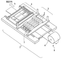
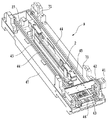
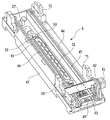
図1は実施形態に係る記録装置の記録部を中心とした主要部の構成を示す斜視図であり、図2は図1の断面構造を示す断面図である。図3は記録装置のクリーニング動作時の状態を示す断面図である。 FIG. 1 is a perspective view showing a configuration of a main part centering on a recording part of a recording apparatus according to an embodiment, and FIG. 2 is a cross-sectional view showing a cross-sectional structure of FIG. FIG. 3 is a cross-sectional view showing a state during the cleaning operation of the recording apparatus.
本実施形態に係る記録装置1は、ライン型の長尺の記録ヘッドを用いて、記録媒体を搬送方向Aに連続搬送しながらプリントを行なうラインプリンタである。ロール状に巻かれた連続紙などの記録媒体4を保持するホルダ8、記録媒体4を所定速度で搬送方向Aに搬送する搬送機構7、および、記録媒体4に対して記録ヘッド2により記録を行なう記録部3を備える。なお、記録媒体4は連続したロール状の記録媒体に限らず、カットされた記録媒体であってもよい。また、記録装置1は、記録ヘッド2のノズル面に付着した付着物を除去するためのクリーニング部6、搬送方向Aの記録部3の下流に設けられた記録媒体4を切断するカッタユニット、記録媒体を強制乾燥する乾燥ユニット、および、排出トレイを備えている。記録部3は、異なるインク色にそれぞれ対応した複数の記録ヘッド2を備える。本例ではCMYKの4色に対応した4つの記録ヘッドとしているが、色数はこれには限定されない。各色のインクはインクタンクからそれぞれインクチューブを介して記録ヘッド2に供給される。複数の記録ヘッド2は、ヘッドホルダ5により一体的に保持されている。さらに、記録装置1は、複数の記録ヘッド2と記録媒体4の表面との間の距離を変更できるよう、ヘッドホルダ5を上下移動させる機構と、ヘッドホルダ5を搬送方向Aと交差する方向に平行移動させる機構を有している。
The recording apparatus 1 according to the present embodiment is a line printer that performs printing while continuously transporting a recording medium in the transport direction A using a line-type long recording head. A holder 8 that holds a
クリーニング部6は、複数(4つ)の記録ヘッド2に対応して複数(4つ)のクリーニング機構9を有する。各クリーニング機構9の詳細は後述する。クリーニング部6は駆動モータ(不図示)により、搬送方向Aにスライド可能となっている。図1および図2は、画像の記録時の状態を示し、クリーニング部6は記録部3に対して搬送方向Aにおいて下流に位置している。一方、図3はクリーニング動作時の状態を示し、クリーニング部6は記録部3の記録ヘッド2の直下に位置している。図2および図3において、クリーニング部6の移動可能範囲を矢印で示している。
The
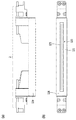
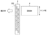
図4は、1つの記録ヘッド2の構造を示す。インクジェット方式は、発熱素子を用いた方式、ピエゾ素子を用いた方式、静電素子を用いた方式、MEMS素子を用いた方式等を採用することができる。記録ヘッド2は、使用が想定される記録媒体の最大幅をカバーする範囲でインクジェット方式のノズル列が形成されたライン型記録ヘッドである。ノズルの配列方向は、搬送方向Aと交差する方向、例えば、搬送方向Aに直交する方向である。
ベース基板124の上に、単一のノズルチップ120が長手方向に沿って配置されている。ノズルチップ120は、図4(b)に示すように、複数のノズルが配列されたノズル列121を複数備えている。
FIG. 4 shows the structure of one
A
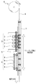
図5および図6は、クリーニング部6と1つのクリーニング機構9の詳細構成を示す斜視図である。図5はクリーニング機構の上に記録ヘッドがある状態(クリーニング動作時)、図6はクリーニング機構の上に記録ヘッドがない状態を示している。クリーニング部
6には、クリーニング機構9、キャップ51および位置決め部材71が設けられている。クリーニング機構9は、記録ヘッド2のノズル面に付着した付着物を除去するワイパユニット46と、ワイパユニット46を払拭方向(ノズル配列方向)に沿って移動させる移動機構と、これらを一体的に支持するフレーム47とを有する。移動機構は、駆動源の駆動によって、2本のシャフト45によって案内支持されたワイパユニット46をノズル配列方向に移動させる。駆動源は、駆動モータ41と減速ギア42、43とを有し、ドライブシャフト37を回転させる。ドライブシャフト37の回転は、ベルト44とプーリで伝達されてワイパユニット46を移動させる。図6において、キャップ51はキャップホルダ52に保持されている。キャップホルダ52は記録ヘッド2のノズル面に対して垂直方向にバネで付勢され、バネの弾性力に抗して移動可能となっている。フレーム47がキャップ位置にある状態で記録ヘッド2がノズル面に対して垂直方向に移動して、キャップ51との接触および離間を行なう。キャップ51との密着によりノズル面をキャッピングすることで、ノズルの乾燥が抑制される。また、キャップ51によってノズル内の増粘したインク液を除去するための予備吐出により排出されたインク滴の回収も行う。位置決め部材71はクリーニング動作時およびキャッピング時においてヘッドホルダ5に設けられたヘッド位置決め部材81と搬送方向A、ノズル配列方向およびノズル面に対して垂直方向の3方向において当接することにより、記録ヘッド2とクリーニング部6の位置関係を決める。
5 and 6 are perspective views showing detailed configurations of the
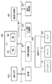
図7は、本発明に係るインクジェット記録装置の制御系を示すブロック図である。図7において、制御系は、メインバスライン805に対して夫々アクセスする画像入力部803、それに対応する画像信号処理部804、CPU800などのソフトウエア処理系と、操作部806、回復系制御回路807、ヘッド駆動制御回路810、搬送方向Aへの紙送り制御回路811などのハードウエア処理系とに大別される。CPU800は、通常ROM(リードオンリメモリ)801とRAM(ランダムアクセスメモリ)802とを有し、入力情報に対して適正な記録条件を与えて記録ヘッド2を駆動して記録を行う。また、RAM802内には、記録ヘッド2の回復処理を実行するプログラムが格納されており、必要に応じてキャップ51内への予備吐出条件等の回復条件を回復系制御回路807および記録ヘッド2に与える。回復系モータ808は、前述したような記録ヘッド2とこれに対向離間するワイパユニット46と、キャップ51と、キャップ51に排出されたインクを吸引する吸引ポンプ811とを駆動する。ヘッド駆動制御回路810は、記録ヘッド2のインク吐出用電気熱変換体の駆動条件を実行するもので、記録ヘッド2の予備吐出制御や記録用インク吐出制御を実行する。
FIG. 7 is a block diagram showing a control system of the ink jet recording apparatus according to the present invention. In FIG. 7, the control system includes an
[第1の実施形態]
本実施形態の記録ヘッド2は、1つのノズルチップ120からなる長尺ヘッドであり、記録媒体の最大幅が10インチのサイズまで記録可能な構成となっている。ノズルから吐出するインク滴の体積は10pl(ピコリットル)である。また、これらのインク滴を安定して吐出するための最大ヘッド駆動周波数は3KHzとする。また本実施形態では連続したロール状の記録媒体4を搬送方向Aに搬送速度5インチ/秒で搬送して、解像度が600×600dpiの画像データを記録する。
[First Embodiment]
The
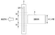
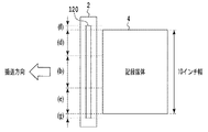
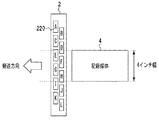
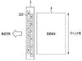
本実施形態においては、図8の記録媒体サイズが4インチ幅の記録媒体に記録を行う記録モードを繰り返し実施している状態から図9の記録媒体サイズが10インチ幅の記録媒体に記録を行う記録モードの状態に変更される場合について図10を参照して説明する。 In the present embodiment, recording is performed on a recording medium having a recording medium size of 10 inches in FIG. 9 from a state where the recording mode in which recording is performed on the recording medium having a recording medium size of 4 inches in FIG. 8 is repeatedly performed. A case where the recording mode is changed will be described with reference to FIG.
図10は、本実施形態の回復処理の動作フローチャートである。CPU800が図10に示す処理を実行させる。
FIG. 10 is an operational flowchart of the recovery process according to this embodiment. The
まず、S1101において印刷ジョブ信号を受信すると、S1102においてキャップ51をオープンする。次に、S1103でこれから記録するための記録モードの情報を受信する。記録モードは、画像の記録に使用する使用ノズルの数および位置に応じて規定され、複数の記録モードが存在する。例えば、記録装置が図8のような記録モードに設定されている場合には、記録モードの情報として、例えば、「記録媒体サイズが4インチ幅」という情報を受信する。図8において、記録媒体は、ノズル配列方向の中央位置に配置されるものとすると、記録媒体サイズが分かれば、画像記録に使用する使用ノズルの数および位置が決まる。なお、記録モードの情報は、使用ノズルの数および位置を特定できるものであればよい。
First, when a print job signal is received in S1101, the
次いで、S1104において、受信した記録モードの情報と前回記録時の記録モードの情報とを比較し、同じかどうかの判断を行う。すなわち、記録モードが変更されたかを検出する。この判断において、記録モードに変更がない場合、すなわち、「Yes」の場合には、ノズルのインク吐出性能を回復させるために第1の予備吐出を実施する。 In step S1104, the received recording mode information is compared with the recording mode information at the previous recording time to determine whether they are the same. That is, it is detected whether the recording mode has been changed. In this determination, if there is no change in the recording mode, that is, “Yes”, the first preliminary ejection is performed in order to restore the ink ejection performance of the nozzle.
本実施形態の第1の予備吐出は、ノズルチップ120に形成されている複数のノズルのうち、設定されている記録モード(S1104において特定した記録モード)における使用ノズル(および、当該使用ノズルの近傍の不使用ノズルから選択的にインクを予備吐出させる。具体的には、図8における(b)の領域のノズル(使用ノズル)および図8における(a)および(c)の領域のノズル(不使用ノズル)からインクを予備吐出させる。
第1の予備吐出において、インクを吐出させる各ノズルからのインク吐出数は、例えば、100発である。この第1の予備吐出回復処理により、キャップクローズ時にノズル内で増粘したインクをキャップ51の中に排出する。
In the first preliminary discharge of the present embodiment, among the plurality of nozzles formed on the
In the first preliminary ejection, the number of ink ejected from each nozzle that ejects ink is, for example, 100. By the first preliminary discharge recovery process, the ink thickened in the nozzle when the cap is closed is discharged into the
次いで、S1107において搬送速度5インチ/秒で記録媒体の搬送を行いながら、S1108において、搬送された4インチ幅の記録媒体に対して画像記録を行う。S1109において、記録媒体への画像記録が終了かどうかの判断を行う。「No」の場合は、S1107に戻り、引き続き記録媒体の搬送とS1108の画像記録を行う。「Yes」の場合は、S1110においてキャップ51によるキャップクローズで記録ヘッドのノズル内のインク乾燥を抑制する。
Next, in step S1107, image recording is performed on the transported recording medium having a width of 4 inches in step S1108 while the recording medium is transported at a transportation speed of 5 inches / second. In step S1109, it is determined whether image recording on the recording medium is complete. If “No”, the process returns to S1107, and the recording medium is continuously conveyed and the image is recorded in S1108. In the case of “Yes”, the ink is dried in the nozzles of the recording head by closing the cap with the
この様に、図8に示した同じ記録モードを繰り返し実施している場合には、図8の(a)〜(c)の領域以外の領域のノズルからインクの予備吐出が実施されないので、無駄なインク消費を抑制することができる。 As described above, when the same recording mode shown in FIG. 8 is repeatedly performed, since preliminary ink ejection is not performed from the nozzles in the regions other than the regions (a) to (c) in FIG. Ink consumption can be suppressed.
次に、図8の記録媒体サイズが4インチ幅の記録媒体に記録する記録モードから図9の記録媒体サイズが10インチ幅の記録媒体に記録する記録モードに変更された場合の処理について説明する。記録モードが図8の状態から図9の状態に変更された場合には、図10のフローチャートのS1103において、変更後の記録モードの情報として、例えば、「記録媒体サイズが10インチ幅」という情報を受信する。S1104において、記録モードが前回記録時と同じかどうかの判断を行うと、「No」となり、S1106において、第2の予備吐出を実施する。 Next, a description will be given of processing when the recording mode in which the recording medium size in FIG. 8 is recorded on a recording medium having a width of 4 inches is changed to the recording mode in which the recording medium size in FIG. 9 is recorded on a recording medium with a width of 10 inches. . When the recording mode is changed from the state of FIG. 8 to the state of FIG. 9, in S1103 of the flowchart of FIG. 10, for example, information indicating that the recording medium size is 10 inches wide is used as the recording mode information after the change. Receive. If it is determined in S1104 whether or not the recording mode is the same as the previous recording, “No” is determined, and in S1106, the second preliminary ejection is performed.
本実施形態の第2の予備吐出処理は、記録モードの変更が検出された場合には、記録媒体への画像の記録の前において、不使用ノズルから新たに使用ノズルとなったノズルおよび当該新たに使用ノズルとなったノズルの近傍の不使用ノズルから選択的にインクを予備吐出させる。具体的には、図9における(d)および(e)の領域のノズルが、不使用ノズルから新たに使用ノズルとなったノズルであり、(f)および(g)の領域のノズルが新たに使用ノズルとなったノズルの近傍の不使用ノズルである。また、図9の領域(b)のノズルは、図8の(b)の領域のノズルと同じであり、既に使用ノズルである。第2の予備吐出処理において、インクを吐出させる各ノズルからのインク吐出数は、例えば、500発であり、第1の予備吐出の場合よりも多くすることが好ましい。この第2の予備吐出回復処理により、キャップオープン時にノズル内で増粘したインクを、キャップ51の中に排出する。
In the second preliminary ejection process of the present embodiment, when a change in the recording mode is detected, before the image is recorded on the recording medium, the nozzle newly used from the unused nozzle and the new nozzle The ink is selectively preliminarily ejected from the unused nozzles in the vicinity of the nozzles that are used nozzles. Specifically, the nozzles in the areas (d) and (e) in FIG. 9 are nozzles that are newly used from the unused nozzles, and the nozzles in the areas (f) and (g) are newly added. It is an unused nozzle in the vicinity of the nozzle that has been used. Further, the nozzle in the region (b) in FIG. 9 is the same as the nozzle in the region (b) in FIG. In the second preliminary ejection process, the number of ink ejected from each nozzle that ejects ink is, for example, 500, and is preferably larger than that in the first preliminary ejection. By the second preliminary discharge recovery process, the ink thickened in the nozzle when the cap is opened is discharged into the
次にS1105において、引き続き、上記した第1の予備吐出処理を実施する。この第1の予備吐出処理によりキャップクローズ時にノズル内で増粘したインクをキャップ51の中に排出する。図9に示す記録モードにおいて、全ての領域(b)、(d)、(e)、(f)および(g)のノズルからインクを予備吐出させる。
In step S1105, the first preliminary discharge process described above is subsequently performed. By the first preliminary discharge process, the ink thickened in the nozzle when the cap is closed is discharged into the
この様に、不使用ノズルから使用ノズルに変更されたノズルからのみインクを予備吐出させることにより、無駄なインク消費を抑制することができる。さらに、新たに使用ノズルとなったノズルの近傍の不使用ノズルからもインクを予備吐出させることで、使用ノズルと不使用ノズルとの境界近傍の不使用ノズルにおけるインクの増粘による画像劣化を防止することができる。 In this way, wasteful ink consumption can be suppressed by preliminarily ejecting ink only from nozzles that have been changed from unused nozzles to used nozzles. In addition, by preliminarily ejecting ink from unused nozzles near the nozzles that have been newly used nozzles, image deterioration due to thickening of ink at unused nozzles near the boundary between used nozzles and unused nozzles is prevented. can do.
[第2の実施形態]
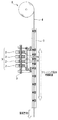
第1の実施形態では、記録ヘッドに1つのノズルチップ120からなる長尺ヘッドを用いた場合について説明したが、本実施形態では、図11に示すように、複数のノズルチップを備える記録ヘッドを用いる場合について説明する。
[Second Embodiment]
In the first embodiment, the case where a long head composed of one
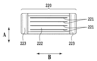
図11に示す記録ヘッド2は、使用が想定される記録媒体の最大幅をカバーする範囲でインクジェット方式のノズル列が形成されたライン型記録ヘッドである。ノズルの配列方向は、記録媒体の搬送方向と交差する方向、例えば直交する方向Bである。同一寸法且つ同一構造の複数(本例では12個)のノズルチップ220が、図11(b)に示すように、ベース基板124の上に、2列の千鳥配置で規則的に配列されている。
A
図12は記録ヘッド2を構成するノズルチップ220の構造を示す図である。ノズルチップ220は、インクを吐出する複数のノズルが配列されたノズル列221が複数形成されたノズル面222を備えると共に、各ノズルに対応して形成されたエネルギ素子が埋め込まれているノズル基板を有する。複数(本例では4つ)のノズル列121は、搬送方向Aにおいて等間隔に並列されている。各ノズル列221は、例えば、1インチ当たり600ドット(600dpi)間隔で960個のノズルが配列され、1.6インチの長さを有する。ノズルチップ220のノズル基板は、ベース基板224の上に設けられている。ノズル基板とベース基板224との間は電気接続部で接続され、電気接続部は樹脂材からなる封止部223で被覆され、腐食や断線が起きないように保護されている。
FIG. 12 is a view showing the structure of the
次に、上記構成の記録ヘッドを用いた回復処理の動作について説明する。なお、第2の実施形態は、基本的な処理について、第1の実施形態と同様であるので、第1の実施形態において用いた図10のフローチャートを参照して、第2の実施形態について説明する。また、図13は、記録媒体サイズが4インチ幅の記録媒体に記録する記録モード、図14は、記録媒体サイズが10インチ幅の記録媒体に記録する記録モードを示す図である。
図13および図14の各ノズルチップ220上のA〜Lは、図11(b)に示した12個のノズルチップ120に対応している。
Next, the operation of the recovery process using the recording head configured as described above will be described. Since the second embodiment is similar to the first embodiment in basic processing, the second embodiment will be described with reference to the flowchart of FIG. 10 used in the first embodiment. To do. FIG. 13 shows a recording mode for recording on a recording medium having a recording medium size of 4 inches wide, and FIG. 14 shows a recording mode for recording on a recording medium having a recording medium size of 10 inches wide.
A to L on each
S1103において受信した記録モードの情報が、図13に示す記録モードである場合であり、S1104において前回記録時の記録モードと同じと判断した場合には、複数のノズルチップ220のうち、設定されている記録モードの使用ノズルを含むノズルチップ220の各々における全てのノズルからインクを予備吐出させることにより、上記した第1の予備吐出処理を実行する。具体的には、図13に示した記録モードの使用ノズルを含むノズルチップ220は、D,E,F,G,H,Iの6個のノズルチップ220であり、これらの6個のノズルチップ220のすべてのノズルからインクを予備吐出させる。この様に、図13に示した同じ記録モードを繰り返し実施している場合には、記録で使用されないノズルチップA,B,C,J,K,Lの6個のノズルチップに対して、予備吐出を実施しないで済むために、無駄なインク消費を抑制することができる。
In the case where the recording mode information received in S1103 is the recording mode shown in FIG. 13 and it is determined in S1104 that the recording mode is the same as the recording mode in the previous recording, it is set among the plurality of nozzle chips 220. The first preliminary discharge process described above is executed by preliminarily discharging ink from all nozzles in each of the
次に、記録モードが図13に示す記録モードから図14に示す記録モードに変更された場合には、S1104において記録モードの変更が検出される。そして、S1106において、不使用ノズルから新たに使用ノズルとなったノズルを含むノズルチップ220の各々における全てのノズルからインクを予備吐出させることにより、上記した第2の予備吐出処理を実行する。具体的には、A,B,C,J,K,Lの6個のノズルチップ220のすべてのノズルからインクを予備吐出させる。
Next, when the recording mode is changed from the recording mode shown in FIG. 13 to the recording mode shown in FIG. 14, a change in the recording mode is detected in S1104. In step S1106, the second preliminary discharge process described above is executed by preliminarily discharging ink from all the nozzles in each of the
次に、S1105において、引き続き第1の予備吐出処理を実施する。本実施形態の第1の予備吐出処理は、図14に示した記録モードにおける使用ノズルを含むノズルチップ内の全てのノズルからインクを予備吐出させる。この第1の予備吐出回復処理によりキャップクローズ時にノズル内で増粘したインクをキャップ51の中に排出する。図14の記録モードにおいて第1の予備吐出させるノズルチップ220は、A〜Lの12個のノズルチップとなる。
Next, in step S1105, the first preliminary discharge process is continued. In the first preliminary ejection process of the present embodiment, ink is preliminary ejected from all nozzles in the nozzle chip including the nozzles used in the recording mode shown in FIG. By the first preliminary discharge recovery process, the ink thickened in the nozzle when the cap is closed is discharged into the
この様に、図13の記録モードから図14の記録モードに切り替わったタイミングにおいてのみ、予備吐出を行うことで無駄なインク消費を抑制することができる。また、不使用ノズルから使用ノズルに切り替わったノズルチップに対してのみ予備吐出を行うことで、今まで使用していたノズルチップD,E,F,G,H,Iの6個のノズルチップに対して、予備吐出を実施しないで済むために、更に無駄なインク消費を抑制することができる。また、使用ノズルを含むノズルチップの全てのノズルから予備吐出させることにより、使用ノズルと不使用ノズルとの境界付近の不使用ノズルから増粘したインクが吐出されるのを回避できるので、画像劣化を防止できる。 In this way, wasteful ink consumption can be suppressed by performing preliminary ejection only at the timing when the recording mode in FIG. 13 is switched to the recording mode in FIG. 14. In addition, by performing preliminary discharge only on the nozzle chips that are switched from the unused nozzles to the used nozzles, the six nozzle chips D, E, F, G, H, and I that have been used so far are used. On the other hand, since it is not necessary to perform preliminary ejection, wasteful ink consumption can be further suppressed. In addition, by pre-discharging from all nozzles of the nozzle chip including the used nozzle, it is possible to avoid discharging thickened ink from the unused nozzle near the boundary between the used nozzle and the unused nozzle. Can be prevented.
[第3の実施形態]
第1および第2の実施形態では、記録モードが記録媒体のサイズに対応して変更される場合について説明したが、本実施形態では、記録ヘッドの複数のノズルにおける使用ノズルの位置の変更に対応して記録モードが変更される場合について説明する。なお、第3の実施形態は、基本的な処理について、第1の実施形態と同様であるので、第1の実施形態において用いた図10のフローチャートを参照して、第3の実施形態について説明する。
[Third Embodiment]
In the first and second embodiments, the case where the recording mode is changed in accordance with the size of the recording medium has been described. However, in the present embodiment, it corresponds to the change in the position of the used nozzle in the plurality of nozzles of the recording head. A case where the recording mode is changed will be described. Since the third embodiment is similar to the first embodiment in basic processing, the third embodiment will be described with reference to the flowchart of FIG. 10 used in the first embodiment. To do.
本実施形態では、例えば、図13に示したような、一定の記録モードの下で、記録ヘッド2の各ノズルチップ内の各ノズルからのインクの吐出数を計測する。そして、各ノズル計測したインク吐出数が所定のインク吐出数を超えた場合には、最もインク吐出数が少ないノズルを含むノズルチップを用いて記録する記録モードに変更する。例えば最も吐出発数が少ないノズルを含むノズルチップ220がAの位置である場合には、図15に示すように、記録ヘッドと記録媒体との位置を相対的に移動させて画像を記録する。このように、使用ノズルの数が同じであっても、使用ノズルの位置の適宜変更を変更することにより、記録ヘッドの耐久寿命を延長させることができる。なお、記録ヘッドと記録媒体との相対位置を変更する機構の詳細説明は省略する。
In the present embodiment, for example, the number of ink ejected from each nozzle in each nozzle chip of the
具体的には、図13に示す記録モードが繰り返されている場合には、S1105において、D,E,F,G,H,Iの6個のノズルチップ220のノズルからインクの予備吐出が実施される。そして、図13に示す記録モードから図15に示す記録モードに変更された場合には、S1104において記録モードの変更が検出され、S1106において第2の予備吐出処理が実施される。このとき、図15に示す記録モードで使用されるノズルチップ220は、A〜Eの位置にあるノズルチップ220であるが、新たに使用ノズルとなったノズルを含むノズルチップ220は、A〜Cの位置にある3つのノズルチップ220である。
Specifically, when the recording mode shown in FIG. 13 is repeated, preliminary ink ejection is performed from the nozzles of the six
次に、S1105において、引き続き第1の予備吐出処理を実施する。本実施形態の第1の予備吐出処理は、図15に示したA〜Eの位置にある各ノズルチップ220内の全てのノズルからインクを予備吐出させる。
Next, in step S1105, the first preliminary discharge process is continued. In the first preliminary ejection process of the present embodiment, ink is preliminarily ejected from all the nozzles in each
このように本実施形態では、第2の予備吐出処理において、今まで使用していたノズルチップD,E,Fの3個のノズルチップについては、インクの予備吐出を実施しないで済むために、無駄なインク消費を抑制することができる。 As described above, in this embodiment, in the second preliminary ejection process, it is not necessary to perform preliminary ink ejection for the three nozzle chips D, E, and F that have been used so far. Wasteful ink consumption can be suppressed.
[その他の実施形態]
第3の実施形態においては、複数のノズルチップを千鳥配列したライン型記録ヘッドを用いた場合について説明したが、図4に示した単一のノズルチップの場合にも、当然実施可能である。
[Other Embodiments]
In the third embodiment, the case of using a line type recording head in which a plurality of nozzle chips are arranged in a staggered manner has been described, but the present invention can naturally be implemented even in the case of the single nozzle chip shown in FIG.
また、上記実施形態においては、記録開始時にのみ第1の予備吐出を実施する場合について説明したが、このタイミングに限定されることはなく、図10のS1110のキャップクローズを行う直前に、記録で使用するノズルを含むノズルチップ内の全てのノズルに対して行う第1の予備吐出を行うことで、画像データがなかった使用ノズル等に対する増粘したノズル内のインクを排出する様にしても良い。 In the above-described embodiment, the case where the first preliminary ejection is performed only at the start of recording has been described. However, the present invention is not limited to this timing, and the recording is performed immediately before the cap closing in S1110 of FIG. By performing the first preliminary discharge for all nozzles in the nozzle chip including the nozzles to be used, the ink in the nozzles with increased viscosity for the used nozzles that have no image data may be discharged. .
また、上記実施形態において、記録媒体に画像記録を行っている時の予備吐出に関して記載していないが、第3の予備吐出処理として画像記録中は使用ノズルを含むノズルチップ単位ではなく、使用ノズルからのみインクを予備吐出させる構成としてもよい。これにより、吐出により発生するインクミスト発生を抑制することができる。 Further, in the above embodiment, there is no description regarding preliminary ejection when image recording is performed on a recording medium. However, during the image recording as the third preliminary ejection processing, not the nozzle chip unit including the used nozzle but the used nozzle. The ink may be preliminarily ejected only from the ink. Thereby, generation | occurrence | production of the ink mist generated by discharge can be suppressed.
また、記録開始時に既にノズル内の泡除去やインク充填、ノズル面に付着した付着物除去等のための回復処理が行われ、ノズル内の増粘インクが解消されている場合には、図10のS1105の第1の予備吐出、S1106の第2の予備吐出を実施しなくても良い。 In addition, when the recovery process for removing bubbles in the nozzle, filling the ink, and removing the adhering matter adhering to the nozzle surface has already been performed at the start of recording and the thickened ink in the nozzle has been eliminated, FIG. The first preliminary discharge in S1105 and the second preliminary discharge in S1106 may not be performed.
また、本発明の第1の予備吐出処理、第2の予備吐出処理におけるインク吐出数は、上記した吐出数に限定されるわけではなく、インク種、インク色、記録ヘッドの配列、ノズル口径、吐出量、キャップクローズ(累積)時間、キャップオープン(累積)時間等に応じて異ならせることができる。 Further, the number of ink ejections in the first preliminary ejection process and the second preliminary ejection process of the present invention is not limited to the above-mentioned ejection number, but the ink type, ink color, printhead arrangement, nozzle diameter, It can be varied according to the discharge amount, cap close (cumulative) time, cap open (cumulative) time, and the like.
2 記録ヘッド
4 記録媒体
51 キャップ
120,220 ノズルチップ
121,221 ノズル列
2
Claims (10)
画像記録に使用する使用ノズルの数および位置に応じて規定された複数の記録モードのうち、設定されている記録モードを特定する手段を有し、
前記予備吐出制御手段は、記録媒体への画像の記録の前又は後において、前記複数のノズルのうち、設定されている記録モードにおける使用ノズルおよび当該使用ノズルの近傍の不使用ノズルから選択的にインクを予備吐出させる第1の予備吐出処理を実行する、ことを特徴とするインクジェット記録装置。 An ink jet recording apparatus comprising: a recording head in which a plurality of nozzles are arranged; and preliminary ejection control means for preliminary ejecting ink from the plurality of nozzles in order to recover ink ejection performance of the plurality of nozzles,
Among a plurality of recording modes defined according to the number and position of the nozzles used for image recording, it has means for specifying the set recording mode,
The preliminary ejection control unit is configured to selectively use a used nozzle in a set recording mode and unused nozzles in the vicinity of the used nozzle among the plurality of nozzles before or after recording an image on a recording medium. An ink jet recording apparatus, wherein a first preliminary ejection process for preliminary ejection of ink is performed.
前記予備吐出制御手段は、前記記録モードの変更が検出された場合には、記録媒体への画像の記録の前において、不使用ノズルから新たに使用ノズルとなったノズルおよび当該新たに使用ノズルとなったノズルの近傍の不使用ノズルから選択的にインクを予備吐出させる第2の予備吐出処理を実行する、ことを特徴とする請求項1に記載のインクジェット記録装置。 Means for detecting whether the recording mode is changed;
When the change in the recording mode is detected, the preliminary ejection control unit includes a nozzle newly used from an unused nozzle and the newly used nozzle before recording an image on a recording medium. The inkjet recording apparatus according to claim 1, wherein a second preliminary discharge process is performed in which ink is selectively preliminarily discharged from an unused nozzle in the vicinity of the nozzle.
前記予備吐出制御手段は、前記複数のノズルチップのうち、設定されている記録モードの使用ノズルを含むノズルチップの各々における全てのノズルからインクを予備吐出させることにより、前記第1の予備吐出処理を実行する、ことを特徴とする請求項1ないし3のいずれかに記載のインクジェット記録装置。 The recording head has a plurality of nozzle chips each having a plurality of nozzles arranged.
The preliminary ejection control means is configured to perform preliminary ejection of ink from all nozzles in each of the nozzle chips including the use nozzles in the set recording mode among the plurality of nozzle chips, thereby performing the first preliminary ejection processing. The inkjet recording apparatus according to claim 1, wherein the inkjet recording apparatus is executed.
前記第3の予備吐出処理は、設定されている記録モードにおける使用ノズルのみからインクを予備吐出させる、ことを特徴とする請求項1ないし7のいずれかに記載のインクジェット記録装置。 The preliminary ejection control means executes a third preliminary ejection process during image recording,
The ink jet recording apparatus according to claim 1, wherein the third preliminary ejection process preliminarily ejects ink only from a use nozzle in a set recording mode.
画像記録に使用する使用ノズルの数および位置に応じて規定される複数の記録モードのうち、設定されている記録モードを特定し、
記録媒体への画像の記録の前又は後において、前記複数のノズルのうち、設定されている記録モードにおける使用ノズルおよび当該使用ノズルの近傍の不使用ノズルから選択的にインクを予備吐出させる第1の予備吐出処理を実行する、ことを特徴とする記録ヘッドの回復処理方法。 A recording head recovery processing method for recovering ink ejection performance of the plurality of nozzles of a recording head in which a plurality of nozzles are arranged,
Among a plurality of recording modes defined according to the number and position of nozzles used for image recording, the set recording mode is specified,
Before or after recording an image on a recording medium, a first ink is selectively preliminarily ejected from a used nozzle in a set recording mode and an unused nozzle in the vicinity of the used nozzle among the plurality of nozzles. A pre-ejection process is performed, and the print head recovery process method is characterized in that:
前記記録モードの変更を検出した場合に、記録媒体への画像の記録の前において、不使用ノズルから新たに使用ノズルとなったノズルおよび当該新たに使用ノズルとなったノズルの近傍の不使用ノズルから選択的にインクを予備吐出させる第2の予備吐出処理を実行する、請求項9に記載の記録ヘッドの回復処理方法。 Detecting that the recording mode has changed,
When a change in the recording mode is detected, before recording an image on a recording medium, a nozzle that has been newly used from an unused nozzle and an unused nozzle in the vicinity of the nozzle that has been newly used The recovery processing method for a recording head according to claim 9, wherein a second preliminary ejection process is performed to preliminarily eject ink selectively.
Priority Applications (2)
| Application Number | Priority Date | Filing Date | Title |
|---|---|---|---|
| JP2011027196A JP5701089B2 (en) | 2011-02-10 | 2011-02-10 | Ink jet recording apparatus and preliminary discharge method |
| US13/365,366 US9321271B2 (en) | 2011-02-10 | 2012-02-03 | Ink jet printing apparatus and recovery method for a print head thereof |
Applications Claiming Priority (1)
| Application Number | Priority Date | Filing Date | Title |
|---|---|---|---|
| JP2011027196A JP5701089B2 (en) | 2011-02-10 | 2011-02-10 | Ink jet recording apparatus and preliminary discharge method |
Publications (3)
| Publication Number | Publication Date |
|---|---|
| JP2012166375A true JP2012166375A (en) | 2012-09-06 |
| JP2012166375A5 JP2012166375A5 (en) | 2014-03-27 |
| JP5701089B2 JP5701089B2 (en) | 2015-04-15 |
Family
ID=46636589
Family Applications (1)
| Application Number | Title | Priority Date | Filing Date |
|---|---|---|---|
| JP2011027196A Active JP5701089B2 (en) | 2011-02-10 | 2011-02-10 | Ink jet recording apparatus and preliminary discharge method |
Country Status (2)
| Country | Link |
|---|---|
| US (1) | US9321271B2 (en) |
| JP (1) | JP5701089B2 (en) |
Cited By (2)
| Publication number | Priority date | Publication date | Assignee | Title |
|---|---|---|---|---|
| JP2014166703A (en) * | 2013-02-28 | 2014-09-11 | Brother Ind Ltd | Liquid ejection apparatus and program used for the liquid ejection apparatus |
| JP2021133514A (en) * | 2020-02-21 | 2021-09-13 | 株式会社リコー | Liquid discharge device and liquid discharge method |
Families Citing this family (3)
| Publication number | Priority date | Publication date | Assignee | Title |
|---|---|---|---|---|
| JP5955053B2 (en) | 2012-03-28 | 2016-07-20 | キヤノン株式会社 | Recording apparatus and recording apparatus control method |
| EP3853028B1 (en) | 2018-09-21 | 2023-07-19 | System Ceramics S.p.A. | Cleaning device for printing heads |
| US11667120B2 (en) * | 2019-12-27 | 2023-06-06 | Ricoh Company, Ltd. | Liquid discharge apparatus |
Citations (9)
| Publication number | Priority date | Publication date | Assignee | Title |
|---|---|---|---|---|
| JPH09193419A (en) * | 1996-01-16 | 1997-07-29 | Seiko Epson Corp | Inkjet recording device |
| JPH09240017A (en) * | 1996-03-04 | 1997-09-16 | Fuji Xerox Co Ltd | Ink jet recording apparatus |
| JP2002347255A (en) * | 2001-05-25 | 2002-12-04 | Canon Aptex Inc | Image recorder |
| JP2003072079A (en) * | 2001-09-04 | 2003-03-12 | Canon Aptex Inc | Recorder and temperature control method |
| JP2005053047A (en) * | 2003-08-01 | 2005-03-03 | Canon Finetech Inc | Inkjet recording device |
| JP2006130690A (en) * | 2004-11-02 | 2006-05-25 | Canon Inc | Inkjet recording apparatus and recovery method |
| JP2008265241A (en) * | 2007-04-24 | 2008-11-06 | Canon Inc | Ink jet recording apparatus and recording head recovery method |
| JP2010125740A (en) * | 2008-11-28 | 2010-06-10 | Ricoh Co Ltd | Image forming apparatus |
| JP2010184363A (en) * | 2009-02-10 | 2010-08-26 | Kyocera Mita Corp | Image forming apparatus |
Family Cites Families (22)
| Publication number | Priority date | Publication date | Assignee | Title |
|---|---|---|---|---|
| US6447095B1 (en) | 1994-05-19 | 2002-09-10 | Canon Kabushiki Kaisha | Discharge recovery method for ink jet apparatus using waterproof ink and ink jet apparatus employing the method |
| US5805180A (en) * | 1994-08-26 | 1998-09-08 | Canon Kabushiki Kaisha | Ink jet recording apparatus which performs suction recovery with a cap and method for same |
| US6193351B1 (en) | 1995-11-27 | 2001-02-27 | Canon Kabushiki Kaisha | System to perform ink jet printing head recovery |
| US6050674A (en) * | 1997-07-28 | 2000-04-18 | Canon Kabushiki Kaisha | Multi-head printer with wide printing mode |
| JP3667117B2 (en) | 1998-10-27 | 2005-07-06 | キヤノン株式会社 | Ink jet recording apparatus and ejection recovery method in the apparatus |
| JP2001063088A (en) | 1999-08-27 | 2001-03-13 | Canon Aptex Inc | Ink-jet recording apparatus and its restoration process method |
| JP4343481B2 (en) * | 2001-02-06 | 2009-10-14 | キヤノン株式会社 | Inkjet recording apparatus and inkjet recording method |
| JP4590129B2 (en) | 2001-06-07 | 2010-12-01 | キヤノン株式会社 | Recording apparatus and preliminary discharge control method |
| JP4464150B2 (en) | 2003-02-26 | 2010-05-19 | キヤノン株式会社 | Ink jet recording apparatus and cleaning control method thereof |
| JP4834466B2 (en) | 2006-06-07 | 2011-12-14 | キヤノン株式会社 | Ink jet recording apparatus and preliminary discharge method |
| JP4412311B2 (en) * | 2006-08-29 | 2010-02-10 | セイコーエプソン株式会社 | Printing method and printing apparatus |
| JP4356720B2 (en) * | 2006-08-29 | 2009-11-04 | セイコーエプソン株式会社 | Printing method and printing apparatus |
| JP5213319B2 (en) | 2006-08-31 | 2013-06-19 | キヤノン株式会社 | Inkjet recording device |
| JP4333732B2 (en) * | 2006-11-30 | 2009-09-16 | コニカミノルタビジネステクノロジーズ株式会社 | Color image forming apparatus |
| JP4986599B2 (en) * | 2006-12-18 | 2012-07-25 | キヤノン株式会社 | Inkjet recording apparatus and inkjet recording method |
| JP4958533B2 (en) | 2006-12-19 | 2012-06-20 | キヤノン株式会社 | Inkjet recording device |
| US20080218547A1 (en) * | 2007-03-06 | 2008-09-11 | Canon Kabushiki Kaisha | Ink jet printing apparatus and ink jet printing method |
| JP5038110B2 (en) | 2007-11-27 | 2012-10-03 | キヤノン株式会社 | Inkjet recording head and inkjet recording apparatus |
| JP5294884B2 (en) | 2008-02-08 | 2013-09-18 | キヤノン株式会社 | Liquid discharge head |
| JP5451103B2 (en) | 2008-03-25 | 2014-03-26 | キヤノン株式会社 | Ink jet recording apparatus and recording head recovery processing method |
| JP2011121197A (en) | 2009-12-08 | 2011-06-23 | Canon Inc | Recovery processing method for recording head, and inkjet recording apparatus using the same |
| JP5328630B2 (en) | 2009-12-18 | 2013-10-30 | キヤノン株式会社 | Inkjet recording apparatus and method for determining number of preliminary ejections |
-
2011
- 2011-02-10 JP JP2011027196A patent/JP5701089B2/en active Active
-
2012
- 2012-02-03 US US13/365,366 patent/US9321271B2/en active Active
Patent Citations (10)
| Publication number | Priority date | Publication date | Assignee | Title |
|---|---|---|---|---|
| JPH09193419A (en) * | 1996-01-16 | 1997-07-29 | Seiko Epson Corp | Inkjet recording device |
| US5992964A (en) * | 1996-01-16 | 1999-11-30 | Seiko Epson Corporation | Ink jet recording apparatus with means for stopping printing and ink jetting capability maintaining operations for one nozzle opening row during a printing operation for another row |
| JPH09240017A (en) * | 1996-03-04 | 1997-09-16 | Fuji Xerox Co Ltd | Ink jet recording apparatus |
| JP2002347255A (en) * | 2001-05-25 | 2002-12-04 | Canon Aptex Inc | Image recorder |
| JP2003072079A (en) * | 2001-09-04 | 2003-03-12 | Canon Aptex Inc | Recorder and temperature control method |
| JP2005053047A (en) * | 2003-08-01 | 2005-03-03 | Canon Finetech Inc | Inkjet recording device |
| JP2006130690A (en) * | 2004-11-02 | 2006-05-25 | Canon Inc | Inkjet recording apparatus and recovery method |
| JP2008265241A (en) * | 2007-04-24 | 2008-11-06 | Canon Inc | Ink jet recording apparatus and recording head recovery method |
| JP2010125740A (en) * | 2008-11-28 | 2010-06-10 | Ricoh Co Ltd | Image forming apparatus |
| JP2010184363A (en) * | 2009-02-10 | 2010-08-26 | Kyocera Mita Corp | Image forming apparatus |
Cited By (3)
| Publication number | Priority date | Publication date | Assignee | Title |
|---|---|---|---|---|
| JP2014166703A (en) * | 2013-02-28 | 2014-09-11 | Brother Ind Ltd | Liquid ejection apparatus and program used for the liquid ejection apparatus |
| JP2021133514A (en) * | 2020-02-21 | 2021-09-13 | 株式会社リコー | Liquid discharge device and liquid discharge method |
| JP7428004B2 (en) | 2020-02-21 | 2024-02-06 | 株式会社リコー | Device for discharging liquid and method for discharging liquid |
Also Published As
| Publication number | Publication date |
|---|---|
| US20120206522A1 (en) | 2012-08-16 |
| US9321271B2 (en) | 2016-04-26 |
| JP5701089B2 (en) | 2015-04-15 |
Similar Documents
| Publication | Publication Date | Title |
|---|---|---|
| JP5955053B2 (en) | Recording apparatus and recording apparatus control method | |
| US8511793B2 (en) | Ejection surface cleaning apparatus, liquid ejection apparatus and ejection surface cleaning method | |
| JP3137529B2 (en) | Wiping member and ink jet recording apparatus provided with the wiping member | |
| JP3950770B2 (en) | Ink jet recording apparatus and preliminary discharge method | |
| JP6652282B2 (en) | Printing equipment | |
| JP5653088B2 (en) | Inkjet recording device | |
| JP4155532B2 (en) | Ink jet recording apparatus and cleaning control method | |
| JP4944631B2 (en) | Inkjet recording apparatus and recovery processing method | |
| JP5701089B2 (en) | Ink jet recording apparatus and preliminary discharge method | |
| JP2000343716A (en) | Inkjet printer head | |
| JP5038110B2 (en) | Inkjet recording head and inkjet recording apparatus | |
| JP6150537B2 (en) | Ink jet recording apparatus and recording head wiping method | |
| JP2004090458A (en) | Ink jet recording apparatus and preliminary ejection method | |
| US9186899B2 (en) | Ink jet printing apparatus | |
| JP3823991B2 (en) | Ink jet recording apparatus and preliminary discharge control method | |
| JP7296761B2 (en) | Recording device and its control method | |
| JP6378961B2 (en) | Inkjet image forming apparatus and cleaning method | |
| JP2007015217A (en) | Inkjet recording apparatus, inkjet recording method, and preliminary discharge control method | |
| JP3909714B2 (en) | Ink jet recording apparatus and preliminary discharge control method | |
| JP5328615B2 (en) | Inkjet recording device | |
| JP2003063033A (en) | Print head refresh method for droplet discharge printing device | |
| JP2009045803A (en) | Ink jet recording apparatus and control method of the recording apparatus | |
| JP2007152636A (en) | Inkjet recording apparatus and ejection recovery control method | |
| JP4016789B2 (en) | Inkjet printer | |
| JP2007331273A (en) | Ink jet recording apparatus and control method of ink jet recording apparatus |
Legal Events
| Date | Code | Title | Description |
|---|---|---|---|
| A521 | Written amendment |
Free format text: JAPANESE INTERMEDIATE CODE: A523 Effective date: 20140207 |
|
| A621 | Written request for application examination |
Free format text: JAPANESE INTERMEDIATE CODE: A621 Effective date: 20140207 |
|
| A977 | Report on retrieval |
Free format text: JAPANESE INTERMEDIATE CODE: A971007 Effective date: 20140910 |
|
| A131 | Notification of reasons for refusal |
Free format text: JAPANESE INTERMEDIATE CODE: A131 Effective date: 20141014 |
|
| A521 | Written amendment |
Free format text: JAPANESE INTERMEDIATE CODE: A523 Effective date: 20141107 |
|
| TRDD | Decision of grant or rejection written | ||
| A01 | Written decision to grant a patent or to grant a registration (utility model) |
Free format text: JAPANESE INTERMEDIATE CODE: A01 Effective date: 20150120 |
|
| A61 | First payment of annual fees (during grant procedure) |
Free format text: JAPANESE INTERMEDIATE CODE: A61 Effective date: 20150217 |
|
| R151 | Written notification of patent or utility model registration |
Ref document number: 5701089 Country of ref document: JP Free format text: JAPANESE INTERMEDIATE CODE: R151 |