JP2012166364A - Die for molding inflation film - Google Patents

Die for molding inflation film Download PDF

Info

Publication number
JP2012166364A
JP2012166364A JP2011027006A JP2011027006A JP2012166364A JP 2012166364 A JP2012166364 A JP 2012166364A JP 2011027006 A JP2011027006 A JP 2011027006A JP 2011027006 A JP2011027006 A JP 2011027006A JP 2012166364 A JP2012166364 A JP 2012166364A
Authority
JP
Japan
Prior art keywords
mandrel
path
peripheral surface
molten resin
outer peripheral
Prior art date
Legal status (The legal status is an assumption and is not a legal conclusion. Google has not performed a legal analysis and makes no representation as to the accuracy of the status listed.)
Withdrawn
Application number
JP2011027006A
Other languages
Japanese (ja)
Inventor
Seiki Kitajima
清貴 北島
Akira Shimizu
明 清水
Current Assignee (The listed assignees may be inaccurate. Google has not performed a legal analysis and makes no representation or warranty as to the accuracy of the list.)
Hokushin Industry Co Ltd
Original Assignee
Hokushin Industry Co Ltd
Priority date (The priority date is an assumption and is not a legal conclusion. Google has not performed a legal analysis and makes no representation as to the accuracy of the date listed.)
Filing date
Publication date
Application filed by Hokushin Industry Co Ltd filed Critical Hokushin Industry Co Ltd
Priority to JP2011027006A priority Critical patent/JP2012166364A/en
Publication of JP2012166364A publication Critical patent/JP2012166364A/en
Withdrawn legal-status Critical Current

Links

Images

Landscapes

  • Extrusion Moulding Of Plastics Or The Like (AREA)

Abstract

PROBLEM TO BE SOLVED: To manufacture a film without uneven thickness or a weld mark in a die for molding the inflation film which forms a molten resin into a tube-like film and extrusion-mold it.SOLUTION: Two distribution channels 12a, 12b expanding in a fan shape toward the outer circumferential surface 9b of a mandrel 9 from an inflow opening 11 formed at the shaft core part of the mandrel 9 as the flow channel of the molten resin, and a cylindrical flow channel 13 formed between the outer circumferential surface 9b of the mandrel 9 and the inner circumferential surface 10a of a die body 10 and formed with an annular lip 14 at an upper part. A tilted partition plate 15 is formed to the radius line of the mandrel 9 at the merging part of the molten resin flowing from the two distribution channels 12a, 12b to the cylindrical flow channel 13.

Description

本発明は、インフレーションフィルム製造装置に用いられるインフレーションフィルム成形用ダイの技術分野に関するものである。   The present invention relates to a technical field of an inflation film forming die used in an inflation film manufacturing apparatus.

インフレーション法によりフィルムを製造するインフレーションフィルム製造装置には、押出機から供給される溶融樹脂を、ダイの上部に形成される環状のリップからチューブ状に押出成形するインフレーションフィルム成形用ダイが用いられるが、該ダイは、一般的に、円柱状のマンドレルと、該マンドレルの外周側に配される円筒状のダイ本体とを備えて構成されると共に、マンドレルの軸芯部に形成される流入口から流入する溶融樹脂を、ダイ上部に形成される環状のリップに導くための流路が形成されている。このようなインフレーションフィルム成形用ダイにおいては、リップから押出成形されるフィルムに偏肉(厚みムラ)やウェルドマーク(筋状の溶融樹脂の合流跡)が発生しないように、溶融樹脂がリップに入るときの円周方向の流量分布を均一にすることが要求される。
そこで従来、溶融樹脂の流路として、流入口からマンドレルの外周部に至る分配路を設けると共に、該分配路に連通する螺旋通路をマンドレルの外周面に形成したスパイラルダイが知られている(例えば、特許文献1参照。)。
また、流入口からマンドレルの外周部に至る分配路を設けると共に、該分配路の外周側端部を基点として扇状に拡がる拡散路をマンドレルの外周面に形成したダイも提唱されている(例えば、特許文献2参照。)。
Inflation film manufacturing equipment that manufactures a film by the inflation method uses an inflation film forming die that extrudes molten resin supplied from an extruder into a tube shape from an annular lip formed at the top of the die. The die is generally configured to include a columnar mandrel and a cylindrical die body disposed on the outer peripheral side of the mandrel, and from an inflow port formed in the mandrel shaft. A flow path for guiding the inflowing molten resin to an annular lip formed on the upper part of the die is formed. In such an inflation film forming die, the molten resin enters the lip so that uneven thickness (thickness unevenness) and weld marks (joint traces of streaky molten resin) do not occur in the film extruded from the lip. It is required to make the flow distribution in the circumferential direction uniform.
Therefore, conventionally, a spiral die in which a distribution path extending from the inlet to the outer periphery of the mandrel is provided as a molten resin flow path and a spiral path communicating with the distribution path is formed on the outer peripheral surface of the mandrel is known (for example, , See Patent Document 1).
In addition, a die having a distribution path extending from the inlet to the outer periphery of the mandrel and having a fan-shaped diffusion path on the outer peripheral surface of the mandrel has also been proposed (for example, (See Patent Document 2).

特開平8−112857号公報JP-A-8-112857 特開2005−289028号公報JP 2005-289028 A

しかしながら、前記特許文献1のようなスパイラルダイにおいて、螺旋通路は狭くて長い通路であるため、該螺旋通路を溶融樹脂が必ずしも均一に流れず、このため、溶融樹脂がリップに入るときの円周方向の流量分布が均一化されずに、フィルムに偏肉やウェルドマークが発生したり、表面が平滑でなかったりするという問題がある。さらに、螺旋通路において溶融樹脂が部分的に滞留してしまうこともあり、この場合には、溶融樹脂が劣化してフィルムの品質低下を招来する惧れがある。尚、特許文献1のものでは、螺旋通路における溶融樹脂の流動性を良くするために、螺旋通路をセラミック材料でコーティングしているが、この場合、セラミック材料を均一の厚さで精度良くコーティングすることは難しく、螺旋通路における溶融樹脂の均一な流れを確保できない惧れがある許りか、コスト高になるという問題が生じる。
一方、特許文献2のものは、分配路の外周側端部を基点として扇状に拡がる拡散路がマンドレルの外周面に形成されると共に、該拡散路の上部にリップが形成されている。このものは、前記特許文献1のような螺旋通路を溶融樹脂が流れるものではないため、溶融樹脂が部分的に滞留してしまう惧れはないが、この特許文献2のものにおいて、拡散路の基点部分から流出した溶融樹脂がリップの円周上の各位相位置に達するまでの距離は、拡散路の基点の位相と同位相位置が最小で、基点の位相から遠い位相位置ほど長くなる。しかしながら、リップに達するまでの距離が長くなるほど溶融樹脂の流れに対する抵抗が大きくなって流量が減少するから、溶融樹脂が拡散路からリップに入るときの円周方向の流量分布が均一にならず、而して、特許文献2のものにおいても、フィムルに偏肉が発生することを払拭できないという問題がある。
また、特許文献2のものでは、二本の分配路が設けられていると共に、各分配路の外周側端部がそれぞれ二つの拡散路の基点になっているが、各分配路から拡散路に流出した溶融樹脂同士は互いに突き合わせ状態で合流するようになっているため、フィルムにウェルドマークが発生してしまうという問題があり、これらに本発明の解決すべき課題がある。
However, in the spiral die as in Patent Document 1, since the spiral passage is a narrow and long passage, the molten resin does not necessarily flow uniformly through the spiral passage. There is a problem that the flow distribution in the direction is not uniform, uneven thickness and weld marks occur in the film, and the surface is not smooth. Furthermore, the molten resin may partially stay in the spiral passage, and in this case, the molten resin may deteriorate, leading to a reduction in film quality. In Patent Document 1, in order to improve the fluidity of the molten resin in the spiral passage, the spiral passage is coated with a ceramic material. In this case, the ceramic material is coated with a uniform thickness with high accuracy. This is difficult, and there is a possibility that the uniform flow of the molten resin in the spiral passage may not be ensured, or there is a problem that the cost becomes high.
On the other hand, in Patent Document 2, a diffusion path that expands in a fan shape from the outer peripheral side end of the distribution path is formed on the outer peripheral surface of the mandrel, and a lip is formed above the diffusion path. Since the molten resin does not flow through the spiral passage as in Patent Document 1, there is no fear that the molten resin partially stays there. The distance until the molten resin flowing out from the base point reaches each phase position on the circumference of the lip is the same as the phase of the base point of the diffusion path, and the distance is longer as the phase position is farther from the phase of the base point. However, as the distance to reach the lip increases, the resistance to the flow of the molten resin increases and the flow rate decreases, so the flow rate distribution in the circumferential direction when the molten resin enters the lip from the diffusion path is not uniform, Therefore, even the thing of patent document 2 has the problem that it cannot wipe off that uneven thickness generate | occur | produces in a film.
Moreover, in the thing of patent document 2, while two distribution paths are provided, the outer peripheral side edge part of each distribution path is a base point of two diffusion paths, respectively. Since the molten resin that has flowed out joins each other in a butted state, there is a problem that a weld mark is generated on the film, and there is a problem to be solved by the present invention.

本発明は、上記の如き実情に鑑みこれらの課題を解決することを目的として創作されたものであって、請求項1の発明は、ダイの上部に形成される環状のリップから溶融樹脂をチューブ状に押出成形するインフレーションフィルム成形用ダイであって、該ダイは、軸芯部に溶融樹脂の流入口が形成される円柱状のマンドレルと、該マンドレルの外周側に配される円筒状のダイ本体とを備える一方、前記流入口から前記環状のリップに至る溶融樹脂の流路として、流入口からマンドレルの外周面に至る二本の分配路と、マンドレルの外周面とダイ本体の内周面との間に形成され、下部が前記分配路に連通し、上部に前記環状のリップが形成される筒状流路とを設けると共に、前記分配路は、流入口を基点としてマンドレルの外周に向かって扇状に拡がるように形成されることを特徴とするインフレーションフィルム成形用ダイである。
請求項2の発明は、ダイの上部に形成される環状のリップから溶融樹脂をチューブ状に押出成形するインフレーションフィルム成形用ダイであって、該ダイは、軸芯部に溶融樹脂の流入口が形成される円柱状のマンドレルと、該マンドレルの外周側に配される円筒状のダイ本体とを備える一方、前記流入口から前記環状のリップに至る溶融樹脂の流路として、流入口からマンドレルの外周面に至る二本の分配路と、マンドレルの外周面とダイ本体の内周面との間に形成され、下部が前記分配路に連通し、上部に前記環状のリップが形成される筒状流路とを設けると共に、該筒状流路を形成するマンドレルの外周面は、前記分配路の外周側端部を基点としてマンドレルの外周面をV字形状に拡がる拡散路と、該拡散路の基点と同位相位置を基点として拡散路の上方に逆三角状形に拡がり、且つ、ダイ本体の内周面との間隔が拡散路よりも狭い整流路とが形成され、さらに、これら拡散路および整流路は、上下方向の長さが拡散路および整流路の基点の位相位置で最大で基点から遠い位相位置ほど短くなるように形成されることを特徴とするインフレーションフィルム成形用ダイである。
請求項3の発明は、請求項1または2において、二本の分配路から筒状流路に流れた溶融樹脂の合流部に、マンドレルの外周面からダイ本体の内周面に向けて突出し、且つ、マンドレルの半径線に対して傾斜状の仕切板を設けて、二本の分配路からの溶融樹脂の流れが互いに楔状に重なりながら合流する構成にしたことを特徴とするインフレーションフィルム成形用ダイである。
The present invention was created with the object of solving these problems in view of the above-mentioned circumstances, and the invention of claim 1 is a method in which a molten resin is tubed from an annular lip formed on an upper portion of a die. A die for forming an inflation film that is extruded into a cylindrical shape, the die having a cylindrical mandrel in which an inlet of a molten resin is formed in an axial center portion, and a cylindrical die disposed on an outer peripheral side of the mandrel A melt resin flow path from the inlet to the annular lip, two distribution passages from the inlet to the outer peripheral surface of the mandrel, an outer peripheral surface of the mandrel, and an inner peripheral surface of the die body A cylindrical flow path having a lower portion communicating with the distribution passage and an upper portion formed with the annular lip, and the distribution passage extending toward the outer periphery of the mandrel from the inlet. Fan A inflation film molding die, characterized in that it is formed so as to extend.
The invention of claim 2 is an inflation film molding die in which a molten resin is extruded into a tube shape from an annular lip formed on the upper portion of the die, and the die has an inlet for the molten resin at the shaft core portion. A cylindrical mandrel that is formed and a cylindrical die body that is disposed on the outer peripheral side of the mandrel, on the other hand, as a molten resin flow path from the inlet to the annular lip, Two distribution paths reaching the outer peripheral surface, a cylindrical shape formed between the outer peripheral surface of the mandrel and the inner peripheral surface of the die body, the lower part communicating with the distribution path, and the annular lip formed on the upper part And the outer peripheral surface of the mandrel that forms the cylindrical flow channel includes a diffusion path that spreads the outer peripheral surface of the mandrel in a V shape from the outer peripheral side end of the distribution path, and the diffusion path Same phase position as base point Then, a rectifying path that extends in an inverted triangular shape above the diffusion path and that is narrower than the diffusion path with respect to the inner peripheral surface of the die body is formed. The inflation film forming die is characterized in that the length of the film is formed so that the phase position at the maximum of the phase position of the base point of the diffusion path and the rectification path becomes shorter as the phase position is farther from the base point.
The invention of claim 3 projects from the outer peripheral surface of the mandrel toward the inner peripheral surface of the die body at the merged portion of the molten resin that has flowed from the two distribution channels into the cylindrical flow channel in claim 1 or 2. An inflation film forming die comprising a partition plate that is inclined with respect to a radial line of the mandrel, and the molten resin flows from the two distribution paths merge while overlapping each other in a wedge shape It is.

請求項1の発明とすることにより、環状のリップに入るときの溶融樹脂の円周方向の流量分布を均一状にすることができて、偏肉の殆どない高品質のフィルムを製造することができる。
請求項2の発明とすることにより、環状のリップに入るときの溶融樹脂の円周方向の流量分布を均一状にすることができて、偏肉の殆どない高品質のフィルムを製造することができる。
請求項3の発明とすることにより、ウェルドマークの発生を確実に低減することができて、より高品質のフィルムを製造することができる。
According to the invention of claim 1, the flow rate distribution in the circumferential direction of the molten resin when entering the annular lip can be made uniform, and a high-quality film with almost no uneven thickness can be produced. it can.
According to the invention of claim 2, the flow distribution in the circumferential direction of the molten resin when entering the annular lip can be made uniform, and a high-quality film with almost no uneven thickness can be produced. it can.
By setting it as invention of Claim 3, generation | occurrence | production of a weld mark can be reduced reliably and a higher quality film can be manufactured.

インフレーションフィルム製造装置の構成図である。It is a block diagram of an inflation film manufacturing apparatus. (A)は第一の実施の形態を示すインフレーションフィルム成形用ダイの縦断面図、(B)は(A)のX−X断面図である。(A) is a longitudinal cross-sectional view of the inflation film-forming die showing the first embodiment, and (B) is an XX cross-sectional view of (A). 図2(A)のY−Y断面展開図である。FIG. 3 is a YY cross-sectional development view of FIG. 図3のX矢視図である。FIG. 4 is a view taken in the direction of arrow X in FIG. 3. (A)は第二の実施の形態を示すインフレーションフィルム成形用ダイの縦断面図、(B)は(A)のX−X断面図である。(A) is a longitudinal cross-sectional view of an inflation film forming die showing a second embodiment, and (B) is an XX cross-sectional view of (A). 図5(A)のY−Y断面展開図である。FIG. 6 is a YY cross-sectional development view of FIG. 図6のX矢視図である。FIG. 7 is a view taken in the direction of arrow X in FIG. 6.

以下、本発明の第一の実施の形態について、図1〜図4に基づいて説明する。
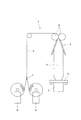
図1において、1はインフレーション法によりフィルムを製造するためのインフレーションフィルム製造装置であって、該インフレーションフィルム製造装置1は、図示しない押出機から供給される溶融樹脂をチューブ状のフィルム2にして押出成形するインフレーションフィルム成形用のダイ3、該ダイ3から押出されたフィルム2を固化させるべく図示しないブロアから供給される冷却風を送風するエアリング4、チューブ状のフィルム2をフラット状に潰す安定板5、フラット状に潰されたフィルム2を送り出すピンチロール6、ピンチロール6から送られるフィルム2を二枚に切り開く切開装置7、切り開かれたフィルム2をロール状に巻取る巻取機8等を用いて構成されている。尚、本実施の形態のインフレーションフィルム製造装置1は、切開装置7で二枚に切り開いたフィルム2をそれぞれ巻取機8に巻取る構成になっているが、フィルム2を切り開くことなく巻取機8に巻取る構成にすることもでき、この場合には切開装置7は設けられない。
Hereinafter, a first embodiment of the present invention will be described with reference to FIGS.
In FIG. 1, reference numeral 1 denotes an inflation film manufacturing apparatus for manufacturing a film by an inflation method. The inflation film manufacturing apparatus 1 extrudes a molten resin supplied from an extruder (not shown) into a tubular film 2. Die 3 for forming an inflation film to be molded, an air ring 4 for blowing cooling air supplied from a blower (not shown) to solidify the film 2 extruded from the die 3, and a tube-shaped film 2 that is crushed into a flat shape A plate 5, a pinch roll 6 that feeds the film 2 crushed into a flat shape, a cutting device 7 that cuts the film 2 fed from the pinch roll 6 into two sheets, a winder 8 that winds the cut film 2 into a roll, and the like It is comprised using. In addition, although the inflation film manufacturing apparatus 1 of this Embodiment is the structure which winds up the film 2 cut into two sheets with the cutting device 7 to the winding machine 8, respectively, the winding machine is not cut open. In this case, the incision device 7 is not provided.

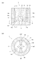
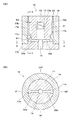
前記インフレーションフィルム成形用のダイ3は、図2に示すように、円柱状のマンドレル9と、該マンドレル9の外周側に配されるダイ本体10とを備えて構成されているが、該ダイ本体10は、マンドレル9の下部から径方向外側に向けて突出形成されるフランジ部9aの上面部に載置される状態で、マンドレル9に組み付けられている。   As shown in FIG. 2, the inflation film forming die 3 includes a cylindrical mandrel 9 and a die body 10 disposed on the outer peripheral side of the mandrel 9. 10 is mounted on the mandrel 9 in a state of being placed on the upper surface portion of the flange portion 9 a that is formed to project outward from the lower portion of the mandrel 9 in the radial direction.

前記マンドレル9は、その下部の軸芯部に、押出機から供給される溶融樹脂が流入する円筒状の流入口11が形成されている。さらに、該流入口11の上部からは、マンドレル9の外周面9bに至る二本の分配路12a、12bが分岐形成されている。これら分配路12a、12bは、上記流入口11を基点としてマンドレル9の外周側に向かって水平方向に扇状に拡がり、且つ、分配路12a、12b同志が流入口11を中心として対称状になるように形成されている。この場合、各分配路12a、12bの流入口11を基点として扇状に拡がる角度αは、マンドレル9の強度を損なわない範囲で可及的に広い角度に設定されている。   The mandrel 9 has a cylindrical inflow port 11 into which a molten resin supplied from an extruder flows is formed in a lower shaft core portion. Furthermore, from the upper part of the inflow port 11, two distribution paths 12 a and 12 b reaching the outer peripheral surface 9 b of the mandrel 9 are branched. These distribution paths 12a and 12b expand in a fan shape in the horizontal direction toward the outer periphery of the mandrel 9 with the inlet 11 as a base point, and the distribution paths 12a and 12b are symmetrical about the inlet 11. Is formed. In this case, the angle α that spreads in a fan shape with the inlet 11 of each distribution path 12a, 12b as a base point is set as wide as possible within a range that does not impair the strength of the mandrel 9.

さらに、前記マンドレル9の外周面9bとダイ本体10の内周面10aとの間には、溶融樹脂の流路となる円筒状の筒状流路13が形成されている。該筒状流路13は、下部が前記二本の分配路12a、12bに連通すると共に、上部に環状のリップ14が形成されている。該リップ14は、ダイ3の上部に形成される溶融樹脂の吐出口であって、該リップ14のクリアランスは、予め設定される所定寸法となるように調整される。尚、筒状流路13の下側のマンドレル9の外周面9bは、ダイ本体10の内周面10aに間隙のない状態で嵌合している。また、図示しないが、マンドレル9には、リップ14から吐出されるチューブ状の溶融樹脂の内方にエアを吹き込んで適宜膨張させるためのエア通路が形成されている。   Further, between the outer peripheral surface 9 b of the mandrel 9 and the inner peripheral surface 10 a of the die body 10, a cylindrical tubular flow path 13 is formed that serves as a flow path for the molten resin. The cylindrical flow path 13 has a lower part communicating with the two distribution paths 12a and 12b, and an annular lip 14 formed on the upper part. The lip 14 is a molten resin discharge port formed on the upper portion of the die 3, and the clearance of the lip 14 is adjusted to have a predetermined dimension set in advance. The outer peripheral surface 9b of the mandrel 9 on the lower side of the cylindrical flow path 13 is fitted to the inner peripheral surface 10a of the die body 10 with no gap. Although not shown, the mandrel 9 is formed with an air passage for blowing air into the inside of the tube-shaped molten resin discharged from the lip 14 and appropriately expanding it.

ここで、前記筒状流路13の下部を形成するマンドレルの外周面9bは、二本の分配路12a、12bに連通する部分が開口していると共に、二本の分配路12a、12bの間に形成される隔壁部9c、9dは、径方向外側に突出してダイ本体10の内周面10aに当接している。該隔壁部9c、9dは、図2(B)、図3に示すように、分配路12a、12bの周回り方向中心位置をマンドレル9の円周上の0°、180°の位相位置としたとき、90°、270°の位相位置に形成されている。そして、二本の分配路12a、12bにより二つの流れに分れた状態でマンドレル9の外周面9bに達した溶融樹脂は、隔壁部9c、9bの上方の筒状流路13において合流することになるが、該合流部には、二つの流れを楔状に重なる状態で合流させるための仕切板15が配されている。   Here, the outer peripheral surface 9b of the mandrel forming the lower part of the cylindrical flow path 13 is open at the portion communicating with the two distribution paths 12a and 12b, and between the two distribution paths 12a and 12b. The partition walls 9 c and 9 d formed on the outer side protrude in the radial direction and abut against the inner peripheral surface 10 a of the die body 10. As shown in FIGS. 2B and 3, the partition wall portions 9 c and 9 d have the center positions in the circumferential direction of the distribution paths 12 a and 12 b as phase positions of 0 ° and 180 ° on the circumference of the mandrel 9. Sometimes, it is formed at a phase position of 90 °, 270 °. The molten resin that has reached the outer peripheral surface 9b of the mandrel 9 in a state of being divided into two flows by the two distribution channels 12a and 12b joins in the cylindrical flow path 13 above the partition walls 9c and 9b. However, a partition plate 15 for joining the two flows so as to overlap each other in a wedge shape is disposed in the joining portion.

前記仕切板15は、図4に示すように、マンドレル9の外周面9bからダイ本体10の内周面10aに向けて突出し、且つ、マンドレル9の半径線に対して傾斜状となるように形成されている。さらに、該仕切板15の外周面には、隔壁部9c、9dの周回り方向一端側を下端として上方に向けて傾斜する外周側傾斜面15aが形成され、また、仕切板15の内周面には、隔壁部9c、9dの周回り方向他端側を下端として上方に向けて傾斜する内周側傾斜面15bが形成されている。これにより、一方の分配路12a、12bを流れて隔壁部9c、9dの周回り方向一端側に達した溶融樹脂は、仕切板15の外周側傾斜面15aに導かれながら仕切板15の外周側を通って上方に流れ、また、他方の分配路12b、12aを流れて隔壁部9c、9dの周回り方向他端側に達した溶融樹脂は、仕切板15の内周側傾斜面15bに導かれて仕切板15の内周側から上方に流れる。而して、二つの流れに分かれた状態でマンドレル9の外周面9bに達した溶融樹脂は、前記仕切板15によって、一方が他方の外周側に、また他方が一方の内周側に入り込む状態で楔状に重なりながら合流するようになっている。   As shown in FIG. 4, the partition plate 15 protrudes from the outer peripheral surface 9 b of the mandrel 9 toward the inner peripheral surface 10 a of the die body 10 and is inclined with respect to the radial line of the mandrel 9. Has been. Furthermore, the outer peripheral surface of the partition plate 15 is formed with an outer peripheral side inclined surface 15a that inclines upward with one end in the circumferential direction of the partition walls 9c and 9d as a lower end, and the inner peripheral surface of the partition plate 15 Is formed with an inner peripheral inclined surface 15b that is inclined upward with the other end in the circumferential direction of the partition walls 9c and 9d as a lower end. As a result, the molten resin that has flowed through one of the distribution channels 12a and 12b and reached one end in the circumferential direction of the partition walls 9c and 9d is guided to the outer peripheral inclined surface 15a of the partition plate 15 while being outer peripheral of the partition plate 15. The molten resin that flows upward through the other distribution passages 12b and 12a and reaches the other end in the circumferential direction of the partition walls 9c and 9d is guided to the inner peripheral inclined surface 15b of the partition plate 15. Accordingly, it flows upward from the inner peripheral side of the partition plate 15. Thus, the molten resin that has reached the outer peripheral surface 9b of the mandrel 9 in a state of being divided into two flows is in a state where one enters the other outer peripheral side and the other enters the one inner peripheral side by the partition plate 15. It is designed to merge while overlapping in a wedge shape.

叙述の如く構成された第一の実施の形態において、インフレーションフィルム成形用のダイ3は、該ダイ3の上部に形成される環状のリップ14から溶融樹脂をチューブ状に押出成形するものであるが、このものは、軸芯部に溶融樹脂の流入口11が形成された円柱状のマンドレル9と、該マンドレル9の外周側に配される円筒状のダイ本体10とを備えて構成される一方、前記流入口11から環状のリップ14に至る溶融樹脂の流路として、流入口11からマンドレル9の外周面9bに至る二本の分配路12a、12bと、マンドレル9の外周面9bとダイ本体10の内周面10aとの間に形成され、下部が上記分配路12a、12bに連通し、上部に前記環状のリップ14が形成される筒状流路13とが設けられていると共に、前記分配路12a、12bは、マンドレル9の流入口11を基点としてマンドレル9の外周に向かって扇状に拡がるように形成されている。   In the first embodiment configured as described above, the die 3 for forming an inflation film is formed by extruding molten resin into a tube shape from an annular lip 14 formed on the upper portion of the die 3. In this configuration, a cylindrical mandrel 9 having a molten resin inflow port 11 formed in the shaft core portion and a cylindrical die body 10 disposed on the outer peripheral side of the mandrel 9 are provided. As the flow path of the molten resin from the inlet 11 to the annular lip 14, two distribution paths 12a and 12b from the inlet 11 to the outer peripheral surface 9b of the mandrel 9, the outer peripheral surface 9b of the mandrel 9 and the die body 10 is formed between the inner peripheral surface 10a, the lower portion communicates with the distribution passages 12a and 12b, and the upper portion is provided with a cylindrical flow passage 13 in which the annular lip 14 is formed. Distribution 12a, 12b are formed so as to extend like a fan toward the outer circumference of the mandrel 9 an inlet 11 of the mandrel 9 as a base point.

而して、マンドレル9の流入口11から流入した溶融樹脂は、二本の分配路12a、12bにより二つの流れに分れた状態でマンドレル9の外周面9bに向かって水平方向に扇状に拡がりながら流れ、さらに該マンドレル9の外周面9bとダイ本体10の内周面10aとの間に形成される筒状流路13を上方に向けて流れて、該筒状流路13の上部に形成される環状のリップ14に至り、該リップ14から吐出されることになるが、この溶融樹脂の流路において、二本の分配路12a、12bにおける流入口11からマンドレル9の外周面9bまでの距離は、マンドレル9の外周面9bの各位相位置で同一であるため、流入口11からマンドレル9の外周面9aに流れる溶融樹脂に対する抵抗は各位相位置で等しいことになる。これにより、分配路12a、12bから筒状流路13に流出する溶融樹脂の流量はマンドレル9の外周面9aの各位相位置で均一状になり、而して、筒状流路13からリップ14に入るときの溶融樹脂の円周方向の流量分布を均一状にすることができて、溶融樹脂が流路の途中で部分的に滞留して劣化してしまう惧れを回避できることは勿論のこと、偏肉の殆どない高品質のフィルム2を製造することができる。   Thus, the molten resin flowing in from the inlet 11 of the mandrel 9 spreads in a fan shape in the horizontal direction toward the outer peripheral surface 9b of the mandrel 9 in a state of being divided into two flows by the two distribution paths 12a and 12b. And further flows upward in the cylindrical flow path 13 formed between the outer peripheral surface 9 b of the mandrel 9 and the inner peripheral surface 10 a of the die body 10, and is formed in the upper part of the cylindrical flow path 13. In this molten resin flow path, from the inlet 11 in the two distribution passages 12a and 12b to the outer peripheral surface 9b of the mandrel 9 is reached. Since the distance is the same at each phase position of the outer peripheral surface 9b of the mandrel 9, the resistance to the molten resin flowing from the inlet 11 to the outer peripheral surface 9a of the mandrel 9 is equal at each phase position. As a result, the flow rate of the molten resin flowing out from the distribution passages 12a and 12b to the cylindrical flow path 13 is uniform at each phase position of the outer peripheral surface 9a of the mandrel 9, and thus the lip 14 from the cylindrical flow path 13 is obtained. The flow rate distribution in the circumferential direction of the molten resin at the time of entering can be made uniform, and it is possible to avoid the possibility that the molten resin partially stays in the middle of the flow path and deteriorates. Thus, a high quality film 2 with almost no uneven thickness can be produced.

しかもこのものにおいて、二本の分配路12a、12bにより二つの流れに分れた溶融樹脂は筒状流路13において合流することになるが、該合流部には、マンドレル9の外周面9bからダイ本体10の内周面10aに向けて突出し、且つ、マンドレル9の半径線に対して傾斜状の仕切板15が設けられており、該仕切板15によって、二本の分配路12a、12bからの溶融樹脂の流れが互いに楔状に重なりながら合流することになる。この結果、合流部におけるウェルドマークの発生を確実に低減することができて、より高品質のフィルム2を製造することができる。しかも、微少なウェルドマークが発生したとしても、二本の分配路12a、12bにより二つの流れに分れた溶融樹脂の合流箇所は2箇所であるから、この部分を切開装置7で切り開くように構成することにより、ウェルドマークの全くないフィルム2を製造することができる。   Moreover, in this case, the molten resin divided into two flows by the two distribution passages 12a and 12b joins in the cylindrical flow path 13, and the joining portion is formed from the outer peripheral surface 9b of the mandrel 9. A partition plate 15 that protrudes toward the inner peripheral surface 10a of the die body 10 and that is inclined with respect to the radial line of the mandrel 9 is provided. By the partition plate 15, the two distribution paths 12a and 12b are separated from each other. The molten resin flows join together while overlapping in a wedge shape. As a result, it is possible to reliably reduce the occurrence of weld marks at the junction, and to manufacture a higher quality film 2. In addition, even if a small weld mark is generated, there are two places where the molten resin is divided into two flows by the two distribution paths 12a and 12b. By comprising, the film 2 without a weld mark can be manufactured.

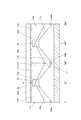
次いで、本発明の第二の実施の形態について、図5〜図7に基づいて説明する。図5において、16は溶融樹脂をチューブ状に押出成形するインフレーションフィルム成形用のダイであって、該ダイ16は、第一の実施の形態のインフレーションフィルム製造装置1と同様のインフレーションフィルム製造装置に設けられる。   Next, a second embodiment of the present invention will be described with reference to FIGS. In FIG. 5, reference numeral 16 denotes an inflation film forming die for extruding a molten resin into a tube shape. The die 16 is an inflation film manufacturing apparatus similar to the inflation film manufacturing apparatus 1 of the first embodiment. Provided.

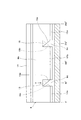
前記第二の実施の形態のダイ16は、図5に示すように、円柱状のマンドレル17と、該マンドレル17の外周側に配されるダイ本体18とを備えて構成されているが、該ダイ本体18は、マンドレル17の下部から径方向外側に向けて突出形成されるフランジ部17aの上面部に載置される状態で、マンドレル17に組み付けられている。   As shown in FIG. 5, the die 16 of the second embodiment includes a cylindrical mandrel 17 and a die body 18 disposed on the outer peripheral side of the mandrel 17. The die body 18 is assembled to the mandrel 17 in a state where the die body 18 is placed on the upper surface portion of the flange portion 17 a that is formed to project outward from the lower portion of the mandrel 17 in the radial direction.

前記マンドレル17は、その下部の軸芯部に、押出機から供給される溶融樹脂が流入する円筒状の流入口19が形成されている。さらに、該流入口19の上部からは、マンドレル17の外周面17bに至る二本の円筒状の分配路20a、20bが分岐形成されているが、これら分配路20a、20b同志は、流入口19を中心として対称状となるように形成されている。   The mandrel 17 has a cylindrical inflow port 19 into which a molten resin supplied from an extruder flows is formed in a lower shaft core portion. Further, two cylindrical distribution passages 20a and 20b are branched from the upper portion of the inflow port 19 to reach the outer peripheral surface 17b of the mandrel 17. The distribution passages 20a and 20b are connected to each other. It is formed so as to be symmetric with respect to the center.

さらに、前記マンドレル17の外周面17bとダイ本体18の内周面18aとの間には、溶融樹脂の流路となる円筒状の筒状流路21が形成されている。該筒状流路21は、下部が前記二本の分配路20a、20bに連通すると共に、上部に環状のリップ22が形成されている。該リップ22は、ダイ16の上部に形成される溶融樹脂の吐出口であって、該リップ22のクリアランスは、予め設定される所定寸法となるように調整される。尚、図示しないが、マンドレル17には、リップ22から吐出されるチューブ状の溶融樹脂の内方にエアを吹き込んで適宜膨張させるためのエア通路が形成されている。   Further, between the outer peripheral surface 17 b of the mandrel 17 and the inner peripheral surface 18 a of the die main body 18, a cylindrical tubular flow channel 21 serving as a molten resin flow channel is formed. The cylindrical channel 21 has a lower portion communicating with the two distribution channels 20a and 20b, and an annular lip 22 formed on the upper portion. The lip 22 is a molten resin discharge port formed on the upper portion of the die 16, and the clearance of the lip 22 is adjusted to have a predetermined dimension set in advance. Although not shown, the mandrel 17 is formed with an air passage for blowing air into the inside of the tube-shaped molten resin discharged from the lip 22 so as to be appropriately expanded.

ここで、前記筒状流路21を形成するマンドレル17の外周面部17bには、二本の分配路20a、20bから筒状流路21を通って環状のリップ22に至る溶融樹脂の円周方向の流量分布を均一状にするべく、後述する拡散路17cと整流路17dとが形成されている。   Here, in the outer peripheral surface portion 17b of the mandrel 17 forming the cylindrical flow path 21, the circumferential direction of the molten resin from the two distribution paths 20a and 20b through the cylindrical flow path 21 to the annular lip 22 is provided. A diffusion path 17c and a rectification path 17d, which will be described later, are formed in order to make the flow rate distribution of the gas flow uniform.

前記拡散路17cは、前記二本の分配路20a、20bの外周側端部を基点としてマンドレル17の外周面17bをV字形状に拡がるように形成されている。つまり、拡散路17cは、図6に示すように、分配路20a、20bの外周側端部の中心位置をマンドレル17の円周上の0°、180°の位相位置としたとき、該0°、180°の位相位置を基点としてV字形状に拡がるように形成されていると共に、該拡散路17cの基点部は、二本の分配路20a、20bの外周側端部に連通している。尚、拡散路17cの下側のマンドレル17の外周面17bは、ダイ本体18の内周面18aに間隙のない状態で嵌合している。   The diffusion path 17c is formed so that the outer peripheral surface 17b of the mandrel 17 is expanded in a V shape with the outer peripheral side end portions of the two distribution paths 20a and 20b as a base point. That is, as shown in FIG. 6, the diffusion path 17c has a 0 ° and 180 ° phase position on the circumference of the mandrel 17 when the center position of the outer peripheral side ends of the distribution paths 20a and 20b is 0 °. , The base point of the diffusion path 17c communicates with the outer peripheral side ends of the two distribution paths 20a and 20b. The outer peripheral surface 17b of the mandrel 17 below the diffusion path 17c is fitted to the inner peripheral surface 18a of the die main body 18 with no gap.

一方、整流路17dは、前記拡散路17cの基点と同位相位置 、つまり0°、180°の位相位置を基点として、拡散路17cの上方に逆三角形状に拡がるように形成されていると共に、該整流路17dの上部には、環状のリップ22が形成されている。この整流路17dにおけるマンドレル17の外周面17bとダイ本体18の内周面18aとの間の間隔D2は、前記拡散路17cにおけるマンドレル17の外周面17bとダイ本体18の内周面18aとの間の間隔D1よりも狭く設定されていて(図5(A)参照)、整流路17dを流れる溶融樹脂の抵抗が拡散路17cよりも大きくなるように構成されている。   On the other hand, the rectifying path 17d is formed so as to expand in an inverted triangle shape above the diffusion path 17c with the same phase position as the base point of the diffusion path 17c, that is, the phase position of 0 ° and 180 ° as the base point. An annular lip 22 is formed on the rectifying path 17d. The distance D2 between the outer peripheral surface 17b of the mandrel 17 and the inner peripheral surface 18a of the die body 18 in the rectifying path 17d is between the outer peripheral surface 17b of the mandrel 17 and the inner peripheral surface 18a of the die body 18 in the diffusion path 17c. The gap is set to be narrower than the interval D1 (see FIG. 5A), and the resistance of the molten resin flowing through the rectifying path 17d is larger than that of the diffusion path 17c.

さらに、マンドレル17の外周面17bの各位相における拡散路17c、整流路17dの上下方向の長さL1、L2は、共に、拡散路17cおよび整流路17dの基点の位相位置で最大で、基点から遠い位相位置ほど短くなるように形成されている。つまり、前記二本の分配路20a、20bにより二つの流れに分れた状態でマンドレル17の外周面17bに達した溶融樹脂は、各分配路20a、20bを基点としてV字形状に拡がる拡散路17cにより、円周方向にV字形状に拡がりながら一部が上方の整流路17dに流れていく。このとき、拡散路17cを流れる溶融樹脂の量は、整流路17dに流れた分だけ減少していく、つまり、基点から遠くなるほど拡散路17cを流れる溶融樹脂量は減少していくが、該溶融樹脂量の減少に対応するべく、拡散路17cの上下方向の長さL1は、基点の位相位置で最大となり基点から遠い位相位置ほど短くなるように形成されている。また、溶融樹脂が各分配路20a、20bの外周側端部を基点として拡散路17c及び整流路17dを流れてリップ22に達するまでの距離は、基点から遠い位相位置ほど長くなるが、該基点から遠い位相位置ほど抵抗の大きい整流路17dを流れる距離が短くなるように、整流路17dの上下方向の長さL2は、基点の位相位置で最大となり基点から遠い位相位置ほど短くなるように形成されている。この場合、拡散路17cおよび整流路17dの上下方向の長さL1、L2は、分配路20a、20bの外周側端部を基点として環状のリップ22の各位相位置に至るまでの溶融樹脂の抵抗が同一となるように設計されており、これにより、リップ22に入るときの溶融樹脂の円周方向の流量分布が均一状になるように構成されている。   Further, the lengths L1 and L2 in the vertical direction of the diffusion path 17c and the rectification path 17d in each phase of the outer peripheral surface 17b of the mandrel 17 are both maximum at the phase positions of the base points of the diffusion path 17c and the rectification path 17d. It is formed so that the farther the phase position is, the shorter. That is, the molten resin that has reached the outer peripheral surface 17b of the mandrel 17 in a state of being divided into two flows by the two distribution paths 20a and 20b spreads in a V-shape from the distribution paths 20a and 20b as a base point. By 17c, a part flows into the upper rectification path 17d, expanding in a V shape in the circumferential direction. At this time, the amount of the molten resin flowing through the diffusion path 17c decreases by the amount that flows into the rectifying path 17d, that is, the amount of the molten resin flowing through the diffusion path 17c decreases as the distance from the base point increases. In order to cope with the decrease in the amount of resin, the length L1 in the vertical direction of the diffusion path 17c is formed so as to be maximum at the phase position of the base point and shorter as the phase position is far from the base point. Further, the distance from the molten resin to the lip 22 through the diffusion path 17c and the rectification path 17d with the outer peripheral side end of each distribution path 20a, 20b as the base point is longer as the phase position is farther from the base point. The length L2 in the vertical direction of the rectifying path 17d is maximized at the phase position of the base point and is shortened as the phase position is far from the base point so that the distance flowing through the rectifying path 17d having a larger resistance becomes shorter at the phase position farther from the base point. Has been. In this case, the lengths L1 and L2 in the vertical direction of the diffusion path 17c and the rectification path 17d are the resistances of the molten resin up to the respective phase positions of the annular lip 22 with the outer peripheral side ends of the distribution paths 20a and 20b as the base points. Are designed to be the same, and thereby, the flow rate distribution in the circumferential direction of the molten resin when entering the lip 22 is configured to be uniform.

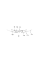
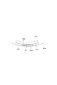
ここで、前記二本の分配路20a、20bの外周側端部の位相位置、つまり0°、180°の位相位置を基点として拡がった溶融樹脂は、拡散路17c及び整流路17dの先端側同志が交わる位相位置、つまり、90°、270°の位相位置部分で合流することになるが、該合流部には、二つの流れを楔状に重なる状態で合流させるための仕切板23が配されている。   Here, the molten resin that has spread based on the phase positions of the outer peripheral ends of the two distribution paths 20a and 20b, that is, the phase positions of 0 ° and 180 °, is the same between the distal ends of the diffusion path 17c and the rectification path 17d. Are joined at the phase position where the two intersect, that is, the phase position portions of 90 ° and 270 °. A partition plate 23 is arranged at the joining portion to join the two flows in a wedge shape. Yes.

前記仕切板23は、前述した第一の実施の形態の仕切板15と同様の構造のものものであって、図7に示す如く、整流路17dからダイ本体18の内周面18aに向けて突出し、且つ、マンドレル17の半径線に対して傾斜状となるように形成されていると共に、該仕切板23の外周面には、一方の整流路17dの先端側下端を下端として上方に向けて傾斜する外周側傾斜面23aが形成され、また、仕切板23の内周面には、他方の整流路17dの先端側下端を下端として上方に向けて傾斜する内周側傾斜面23bが形成されている。これにより、二つの流れに分かれた状態で拡散路17c及び整流路17dの先端側に達した溶融樹脂は、前記仕切板23によって、一方が他方の外周側に、また他方が一方の内周側に入り込む状態で楔状に重なりながら合流するようになっている。   The partition plate 23 has the same structure as the partition plate 15 of the first embodiment described above, and is directed from the rectifying path 17d toward the inner peripheral surface 18a of the die body 18 as shown in FIG. It protrudes and is formed so as to be inclined with respect to the radial line of the mandrel 17, and on the outer peripheral surface of the partition plate 23, the lower end on the front end side of one rectifying path 17d is directed upward. An inclined outer peripheral inclined surface 23a is formed, and an inner peripheral inclined surface 23b is formed on the inner peripheral surface of the partition plate 23. The inner peripheral inclined surface 23b is inclined upward with the lower end on the front end side of the other rectifying passage 17d as a lower end. ing. As a result, the molten resin that has reached the distal end side of the diffusion path 17c and the rectifying path 17d in a state of being divided into two flows is divided into one on the other outer peripheral side and the other on the inner peripheral side by the partition plate 23. It is designed to merge while overlapping in a wedge shape.

叙述の如く構成された第二の実施の形態において、インフレーションフィルム成形用のダイ16は、第一の実施の形態のダイ3と同様に、軸芯部に溶融樹脂の流入口19が形成された円柱状のマンドレル17と、該マンドレル17の外周側に配される円筒状のダイ本体18とを備えて構成されているが、第二の実施の形態のダイ16は、前記流入口19から環状のリップ22に至る溶融樹脂の流路として、流入口19からマンドレル17の外周面17bに至る二本の分配路20a、20bと、マンドレル17の外周面17bとダイ本体18の内周面18aとの間に形成され、下部が上記分配路20a、20bに連通し、上部に前記環状のリップ22が形成される筒状流路21とが設けられる一方、該筒状流路21を形成するマンドレル17の外周面17bには、前記分配路20a、20bの外周側端部を基点としてマンドレル17の外周面17bをV字形状に拡がる拡散路17cと、該拡散路17cの基点と同位相位置を基点として拡散路17cの上方に逆三角状形に拡がり、且つ、ダイ本体18の内周面18aとの間隔D2が拡散路17cにおける間隔D1よりも狭い整流路17dとが形成されている。さらに、マンドレル17の外周面17bの各位相における拡散路17cおよび整流路17dの上下方向の長さL1、L2は、拡散路17cおよび整流路17dの基点の位相位置で最大となり基点から遠い位相位置ほど短くなるように形成されている。   In the second embodiment configured as described above, the die 16 for forming an inflation film has a molten resin inlet 19 formed in the shaft core portion in the same manner as the die 3 of the first embodiment. Although the cylindrical mandrel 17 and the cylindrical die body 18 disposed on the outer peripheral side of the mandrel 17 are provided, the die 16 according to the second embodiment has an annular shape from the inflow port 19. As the flow path of the molten resin reaching the lip 22, two distribution paths 20 a and 20 b extending from the inlet 19 to the outer peripheral surface 17 b of the mandrel 17, the outer peripheral surface 17 b of the mandrel 17, and the inner peripheral surface 18 a of the die body 18 A mandrel that forms the cylindrical channel 21 is provided between the distribution channel 20a, 20b and a cylindrical channel 21 in which the annular lip 22 is formed. 17's On the peripheral surface 17b, a diffusion path 17c that expands the outer peripheral surface 17b of the mandrel 17 in a V shape with the outer peripheral side ends of the distribution paths 20a, 20b as a base point, and the same phase position as the base point of the diffusion path 17c as a base point A rectifying path 17d is formed above the diffusion path 17c so as to expand in an inverted triangular shape, and the distance D2 from the inner peripheral surface 18a of the die body 18 is narrower than the distance D1 in the diffusion path 17c. Further, the lengths L1 and L2 in the vertical direction of the diffusion path 17c and the rectification path 17d in each phase of the outer peripheral surface 17b of the mandrel 17 are maximum at the phase positions of the base points of the diffusion path 17c and the rectification path 17d and are far from the base point. It is formed to be as short as possible.

而して、マンドレル17の流入口19から流入した溶融樹脂は、二本の分配路20a、20bにより二つの流れに分れてマンドレル17の外周面17bに達し、さらに、各分配路20a、20bの外周側端部を基点としてV字形状に拡がる拡散路17cにより円周方向に拡がりながら上方の整流路17dに流れ、該整流路17dを通って環状のリップ22に至ることになるが、この場合に、整流路17dにおけるマンドレル17の外周面17bとダイ本体18の内周面18aとの間の間隔D2が、拡散路17cにおけるマンドレル17の外周面17bとダイ本体18の内周面18aとの間の間隔D1よりも狭く設定されて、整流路17dを流れる溶融樹脂の抵抗が拡散路17cよりも大きいと共に、マンドレル17の外周面17bの各位相における拡散路17cおよび整流路17dの上下方向の長さL1、L2は、拡散路17cおよび整流路17dの基点の位相位置で最大となり基点から遠い位相位置ほど短くなるように形成されているため、前述したように、整流路17dからリップ22に入るときの溶融樹脂の円周方向の流量分布を均一状にすることができて、溶融樹脂が流路の途中で部分的に滞留して劣化してしまう惧れを回避できることは勿論のこと、偏肉の殆どない高品質のフィルム2を製造することができる。   Thus, the molten resin flowing in from the inlet 19 of the mandrel 17 is divided into two flows by the two distribution passages 20a and 20b, and reaches the outer peripheral surface 17b of the mandrel 17, and further, each distribution passage 20a, 20b. It flows to the upper rectification path 17d while spreading in the circumferential direction by the diffusion path 17c that spreads in a V shape with the outer peripheral side end as a base point, and reaches the annular lip 22 through the rectification path 17d. In this case, the distance D2 between the outer peripheral surface 17b of the mandrel 17 and the inner peripheral surface 18a of the die body 18 in the rectifying path 17d is equal to the outer peripheral surface 17b of the mandrel 17 and the inner peripheral surface 18a of the die body 18 in the diffusion path 17c. The resistance of the molten resin flowing through the rectifying path 17d is larger than that of the diffusion path 17c and is set to be smaller in each phase of the outer peripheral surface 17b of the mandrel 17. The vertical lengths L1 and L2 of the diffusion path 17c and the rectification path 17d are formed so as to be maximum at the phase position of the base point of the diffusion path 17c and the rectification path 17d and to be shorter as the phase position is far from the base point. As described above, the flow rate distribution in the circumferential direction of the molten resin when entering the lip 22 from the rectifying path 17d can be made uniform, and the molten resin partially stays in the middle of the flow path and deteriorates. As a matter of course, it is possible to produce a high-quality film 2 with almost no uneven thickness.

しかもこのものにおいて、各分配路20a、20bの外周側端部を基点とする溶融樹脂の二つの流れは拡散路17cおよび整流路17dの先端側において合流することになるが、該合流部には、整流路17dからダイ本体18の内周面18aに向けて突出し、且つ、マンドレル17の半径線に対して傾斜状の仕切板23が設けられており、該仕切板23によって、二本の分配路20a、20bからの溶融樹脂の流れが互いに楔状に重なりながら合流することになる。この結果、第二の実施の形態のものにおいても、第一の実施の形態と同様に、合流部におけるウェルドマークの発生を確実に低減することができて、より高品質のフィルム2を製造することができる。しかも、微小なウェルドマークが発生したとしても、二本の分配路20a、20bにより二つの流れに分れた溶融樹脂の合流箇所は2箇所であるから、この部分を切開装置7で切り開くように構成することにより、ウェルドマークの全くないフィルム2を製造することができる。   In addition, in this case, the two flows of the molten resin starting from the outer peripheral end of each distribution channel 20a, 20b merge at the distal end side of the diffusion channel 17c and the rectification channel 17d. The partition plate 23 protrudes from the rectifying path 17d toward the inner peripheral surface 18a of the die body 18 and is inclined with respect to the radial line of the mandrel 17, and the partition plate 23 allows two distributions to be distributed. The molten resin flows from the paths 20a and 20b join together while overlapping in a wedge shape. As a result, also in the second embodiment, as in the first embodiment, it is possible to reliably reduce the occurrence of weld marks at the junction, and manufacture a higher quality film 2. be able to. In addition, even if a minute weld mark is generated, there are two places where the molten resin is divided into two flows by the two distribution paths 20a and 20b. By comprising, the film 2 without a weld mark can be manufactured.

本発明は、インフレーション法によりフィルムを製造するインフレーションフィルム製造装置に用いられるインフレーションフィルム成形用ダイに利用することができる。   INDUSTRIAL APPLICABILITY The present invention can be used for an inflation film forming die used in an inflation film production apparatus for producing a film by an inflation method.

3 ダイ
9 マンドレル
10 ダイ本体
11 流入口
12a、12b 分配路
13 筒状流路
14 リップ
15 仕切板
16 ダイ
17 マンドレル
17c 拡散路
17d 整流路
18 ダイ本体
19 流入口
20a、20b 分配路
21 筒状流路
22 リップ
23 仕切板
3 Die 9 Mandrel 10 Die body 11 Inlet 12a, 12b Distribution path 13 Cylindrical channel 14 Lip 15 Partition plate 16 Die 17 Mandrel 17c Diffusion path 17d Rectification path 18 Die body 19 Inlet 20a, 20b Distribution path 21 Cylindrical flow Road 22 Lip 23 Partition plate

Claims (3)

ダイの上部に形成される環状のリップから溶融樹脂をチューブ状に押出成形するインフレーションフィルム成形用ダイであって、該ダイは、軸芯部に溶融樹脂の流入口が形成される円柱状のマンドレルと、該マンドレルの外周側に配される円筒状のダイ本体とを備える一方、前記流入口から前記環状のリップに至る溶融樹脂の流路として、流入口からマンドレルの外周面に至る二本の分配路と、マンドレルの外周面とダイ本体の内周面との間に形成され、下部が前記分配路に連通し、上部に前記環状のリップが形成される筒状流路とを設けると共に、前記分配路は、流入口を基点としてマンドレルの外周に向かって扇状に拡がるように形成されることを特徴とするインフレーションフィルム成形用ダイ。   An inflation film molding die for extruding a molten resin into a tube shape from an annular lip formed on an upper portion of a die, the die being a cylindrical mandrel in which an inlet of a molten resin is formed in a shaft core portion And a cylindrical die body disposed on the outer peripheral side of the mandrel, and as a flow path of the molten resin from the inlet to the annular lip, two pipes extending from the inlet to the outer peripheral surface of the mandrel A distribution path, a cylindrical flow path formed between the outer peripheral surface of the mandrel and the inner peripheral surface of the die body, the lower part communicating with the distribution path, and the annular lip formed on the upper part are provided, The inflation film forming die, wherein the distribution path is formed to expand in a fan shape toward an outer periphery of a mandrel with an inflow port as a base point. ダイの上部に形成される環状のリップから溶融樹脂をチューブ状に押出成形するインフレーションフィルム成形用ダイであって、該ダイは、軸芯部に溶融樹脂の流入口が形成される円柱状のマンドレルと、該マンドレルの外周側に配される円筒状のダイ本体とを備える一方、前記流入口から前記環状のリップに至る溶融樹脂の流路として、流入口からマンドレルの外周面に至る二本の分配路と、マンドレルの外周面とダイ本体の内周面との間に形成され、下部が前記分配路に連通し、上部に前記環状のリップが形成される筒状流路とを設けると共に、該筒状流路を形成するマンドレルの外周面は、前記分配路の外周側端部を基点としてマンドレルの外周面をV字形状に拡がる拡散路と、該拡散路の基点と同位相位置を基点として拡散路の上方に逆三角状形に拡がり、且つ、ダイ本体の内周面との間隔が拡散路よりも狭い整流路とが形成され、さらに、これら拡散路および整流路は、上下方向の長さが拡散路および整流路の基点の位相位置で最大で基点から遠い位相位置ほど短くなるように形成されることを特徴とするインフレーションフィルム成形用ダイ。   An inflation film molding die for extruding a molten resin into a tube shape from an annular lip formed on an upper portion of a die, the die being a cylindrical mandrel in which an inlet of a molten resin is formed in a shaft core portion And a cylindrical die body disposed on the outer peripheral side of the mandrel, and as a flow path of the molten resin from the inlet to the annular lip, two pipes extending from the inlet to the outer peripheral surface of the mandrel A distribution path, a cylindrical flow path formed between the outer peripheral surface of the mandrel and the inner peripheral surface of the die body, the lower part communicating with the distribution path, and the annular lip formed on the upper part are provided, The outer peripheral surface of the mandrel that forms the cylindrical flow path is based on a diffusion path that expands the outer peripheral surface of the mandrel in a V shape from the outer peripheral side end of the distribution path, and the same phase position as the base point of the diffusion path As above the diffusion path A rectifying path that extends in an inverted triangular shape and that is narrower than the diffusion path with respect to the inner peripheral surface of the die body is formed, and the diffusion path and the rectifying path have a length in the vertical direction of the diffusion path and An inflation film forming die characterized in that it is formed such that the phase position at the maximum at the phase position of the base point of the rectifying path becomes shorter as the phase position is far from the base point. 請求項1または2において、二本の分配路から筒状流路に流れた溶融樹脂の合流部に、マンドレルの外周面からダイ本体の内周面に向けて突出し、且つ、マンドレルの半径線に対して傾斜状の仕切板を設けて、二本の分配路からの溶融樹脂の流れが互いに楔状に重なりながら合流する構成にしたことを特徴とするインフレーションフィルム成形用ダイ。   In Claim 1 or 2, it protrudes from the outer peripheral surface of the mandrel toward the inner peripheral surface of the die body at the joining portion of the molten resin that has flowed from the two distribution passages into the cylindrical flow passage, and the radial line of the mandrel An inflation film forming die characterized in that an inclined partition plate is provided so that the flow of molten resin from two distribution passages merge while overlapping each other in a wedge shape.
JP2011027006A 2011-02-10 2011-02-10 Die for molding inflation film Withdrawn JP2012166364A (en)

Priority Applications (1)

Application Number Priority Date Filing Date Title
JP2011027006A JP2012166364A (en) 2011-02-10 2011-02-10 Die for molding inflation film

Applications Claiming Priority (1)

Application Number Priority Date Filing Date Title
JP2011027006A JP2012166364A (en) 2011-02-10 2011-02-10 Die for molding inflation film

Publications (1)

Publication Number Publication Date
JP2012166364A true JP2012166364A (en) 2012-09-06

Family

ID=46971019

Family Applications (1)

Application Number Title Priority Date Filing Date
JP2011027006A Withdrawn JP2012166364A (en) 2011-02-10 2011-02-10 Die for molding inflation film

Country Status (1)

Country Link
JP (1) JP2012166364A (en)

Similar Documents

Publication Publication Date Title
CN106163766B (en) Thickness-nonuniform adjustment type gas ring
JP4527776B2 (en) Film blow mold for producing tubular film
JP4426937B2 (en) Rubber strip manufacturing equipment
JP5795940B2 (en) Equipment for the production of thermoplastic pipes
US8096799B2 (en) Swept leg spider for an extrusion apparatus
US7517210B1 (en) Apparatus for the manufacture of compound pipes
JP2012166364A (en) Die for molding inflation film
JP2009034915A (en) Extrusion machine for producing conductive rubber roll
JP2014180785A (en) Apparatus and method for rubber molding
JP2018123882A (en) Resin pipe fittings
JP2011183750A (en) Extruder, and molding die used for the same
JP4786288B2 (en) Double flow path for extruder head
US8641396B2 (en) Spiral distributor, die head, blown film line, and method for manufacturing a blown film
JP6039846B1 (en) Inflation film forming die
CN210966412U (en) Extrusion die of two hollow square-mouth aluminum alloy sections
JP2023054461A (en) die for extrusion molding
CN113877978A (en) Extrusion die capable of offsetting fusion port to non-stressed position of section bar
JP2017170790A (en) Producing apparatus for rubber roll
JP2005205658A (en) Extrusion mold and extrusion molding method
JPH04103327A (en) Extrusion mold
JP2003211521A (en) Mold for extrusion molding of hollow pipe
CN207372052U (en) Double Hole Mold
JP6039845B1 (en) Inflation film forming die
JPS5913972B2 (en) spider type pipe die
JP2020121482A (en) Crosshead die and extruder

Legal Events

Date Code Title Description
A300 Withdrawal of application because of no request for examination

Free format text: JAPANESE INTERMEDIATE CODE: A300

Effective date: 20140513