JP2012166329A - Handheld belt sander - Google Patents
Handheld belt sander Download PDFInfo
- Publication number
- JP2012166329A JP2012166329A JP2011031604A JP2011031604A JP2012166329A JP 2012166329 A JP2012166329 A JP 2012166329A JP 2011031604 A JP2011031604 A JP 2011031604A JP 2011031604 A JP2011031604 A JP 2011031604A JP 2012166329 A JP2012166329 A JP 2012166329A
- Authority
- JP
- Japan
- Prior art keywords
- belt
- sander
- pulley
- guide
- guide surface
- Prior art date
- Legal status (The legal status is an assumption and is not a legal conclusion. Google has not performed a legal analysis and makes no representation as to the accuracy of the status listed.)
- Withdrawn
Links
- 230000002093 peripheral effect Effects 0.000 description 13
- 238000003754 machining Methods 0.000 description 3
- 239000006061 abrasive grain Substances 0.000 description 2
- 230000005540 biological transmission Effects 0.000 description 2
- 210000000078 claw Anatomy 0.000 description 2
- 239000000463 material Substances 0.000 description 2
- 239000002184 metal Substances 0.000 description 2
- 238000000034 method Methods 0.000 description 2
- 230000008569 process Effects 0.000 description 2
- 230000008901 benefit Effects 0.000 description 1
- 238000010586 diagram Methods 0.000 description 1
- 238000012986 modification Methods 0.000 description 1
- 230000004048 modification Effects 0.000 description 1
- 230000009467 reduction Effects 0.000 description 1
- 238000009751 slip forming Methods 0.000 description 1
Images
Landscapes
- Finish Polishing, Edge Sharpening, And Grinding By Specific Grinding Devices (AREA)
Abstract
Description
本発明は、木工製品や金属製品の仕上げ加工などに用いる手持ち式ベルトサンダに関する。 The present invention relates to a hand-held belt sander used for finishing a woodwork product or a metal product.
一般に、木工製品や金属製品の仕上げ加工などに用いる手持ち式ベルトサンダは、把持部を有する本体の前部に、本体に装備されたモータから駆動力を得て回転する駆動プーリと、この駆動プーリのさらに前方に配置した従動プーリと、駆動プーリおよび従動プーリとの間に張架した無端のサンダベルトを有する。 In general, a hand-held belt sander used for finishing a woodworking product or a metal product has a driving pulley that rotates at the front of a main body having a gripping portion by obtaining driving force from a motor mounted on the main body, and the driving pulley. A driven pulley disposed further forward of the belt and an endless sander belt stretched between the driving pulley and the driven pulley.
上記手持ち式ベルトサンダにおいては、平面に形成されたガイド面を有するベルトガイドがサンダベルト内面側に装備されており、このガイド面がサンダベルトを加工面に押圧した際の支持面として機能することで平面加工を効率良く行うことができる。また、丸棒等の外周面を加工する場合の作業効率向上のために、ベルトガイドのガイド面の一部に凹部を設ける構成も知られている(例えば、特許文献1参照)。 In the hand-held belt sander, a belt guide having a flat guide surface is provided on the inner surface of the sander belt, and this guide surface functions as a support surface when the sander belt is pressed against the processing surface. With this, planar processing can be performed efficiently. In addition, a configuration is also known in which a recess is provided in a part of the guide surface of the belt guide in order to improve working efficiency when processing the outer peripheral surface of a round bar or the like (see, for example, Patent Document 1).
ところで、上述の手持ち式ベルトサンダを使用してリング形状部品の内周面の加工を行う場合、サンダベルトは平面に形成されたガイド面により支持されているため、加工面である内周面をサンダベルトにより押圧した際に、サンダベルトの幅方向両端あるいは一端のみが摺接することになり効率の良い加工作業を行うことが困難となる。さらに、サンダベルトの端部のみが摺接するため、端部において研磨砥粒の剥離およびベルト基材の損傷が早期に発生してしまい、サンダベルトの交換を余儀なくされてしまう。 By the way, when the inner peripheral surface of the ring-shaped part is processed using the above-described handheld belt sander, the sander belt is supported by a guide surface formed on a flat surface. When pressed by the sander belt, only the both ends or one end in the width direction of the sander belt come into sliding contact, making it difficult to perform an efficient processing operation. Furthermore, since only the end portion of the sander belt is in sliding contact, the abrasive grains are peeled off at the end portion and the belt base material is damaged at an early stage, and the sander belt must be replaced.
また、上述の問題を回避するためにベルトガイドのガイド面に設けられた凹部を使用して内周面を加工することも考えられる。この場合、サンダベルトが凹部底面に当接しない程度に押圧してサンダベルトを内周面に倣って変形させて加工することになるが、サンダベルトの加工面への押圧力は、サンダベルトに負荷されている張力のみにより付与されるため、サンダベルトの進行方向において摺接範囲の始端部と終端部で強くなってしまう。このため、サンダベルトの進行方向において加工除去量が著しく不均一となり、精度の高い加工ができないことになる。さらに、ガイド面に支持されていないためサンダベルトが不安定な状態で加工することになる点からも加工精度の低下が危惧される。 In order to avoid the above-mentioned problem, it is also conceivable to process the inner peripheral surface using a recess provided in the guide surface of the belt guide. In this case, the sander belt is pressed to such an extent that it does not come into contact with the bottom surface of the recess, and the sander belt is deformed following the inner peripheral surface, and the pressing force on the processing surface of the sander belt is applied to the sander belt. Since it is applied only by the applied tension, it becomes strong at the start and end portions of the sliding contact range in the direction of travel of the sander belt. For this reason, the processing removal amount becomes extremely nonuniform in the traveling direction of the sander belt, and high-precision processing cannot be performed. Furthermore, since the sander belt is not supported by the guide surface, the processing accuracy may be lowered because the sander belt is processed in an unstable state.
本発明は上記問題を解決するためになされたもので、その目的は内周面を正確かつ作業性良く加工することができる新たな手持ち式ベルトサンダを提供することである。 The present invention has been made to solve the above problems, and an object of the present invention is to provide a new hand-held belt sander capable of processing the inner peripheral surface accurately and with good workability.
本発明に係る手持ち式ベルトサンダは、駆動源により回転駆動される駆動プーリと、前記駆動プーリと離間して回動自在に設置された従動プーリと、前記駆動プーリと前記従動プーリとの間に張架された無端のサンダベルトと、前記サンダベルトの内面側に装備され前記サンダベルトを支持するガイド面を有するベルトガイドと、を備え、前記ガイド面は、前記サンダベルトの進行方向に垂直な断面視において前記サンダベルトへ向かってR形状に形成されるR形状部を備えることを特徴とする。 A hand-held belt sander according to the present invention includes a drive pulley that is rotationally driven by a drive source, a driven pulley that is rotatably disposed apart from the drive pulley, and a gap between the drive pulley and the driven pulley. An endless sander belt that is stretched; and a belt guide that is provided on the inner surface side of the sander belt and has a guide surface that supports the sander belt, and the guide surface is perpendicular to the traveling direction of the sander belt. An R-shaped portion formed in an R shape toward the sander belt in a cross-sectional view is provided.
本発明によれば、内周面を正確かつ作業性良く加工することができる新たな手持ち式ベルトサンダを提供することができる。 ADVANTAGE OF THE INVENTION According to this invention, the new handheld belt sander which can process an internal peripheral surface correctly and with sufficient workability | operativity can be provided.
以下、本発明を実施するための好適な実施形態について、図1〜図5を用いて説明する。なお、以下の実施形態は、請求項に係る発明を限定するものではなく、また、実施形態の中で説明されている特徴の組み合わせの全てが発明の解決手段に必須であるとは限らない。 Hereinafter, a preferred embodiment for carrying out the present invention will be described with reference to FIGS. The following embodiments do not limit the invention according to the claims, and all combinations of features described in the embodiments are not necessarily essential to the solution means of the invention.
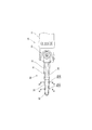
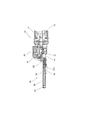
図1は、本実施形態に係る手持ち式ベルトサンダの要部平面図である。図2は図1の長手方向断面図である。図1及び図2に示されるように、本実施形態に係る手持ち式ベルトサンダは、主として駆動部を内包する本体部10と、本体部10より左方(前方)に延設されるアーム部30と、後述する駆動プーリ21と、アーム部30の左方先端部に回動自在に設けられる従動プーリ22と、駆動プーリ21と従動プーリ22との間に張架される無端のサンダベルト41とを備えている。本体部10は、ハウジング11と、ハウジング11の内部に配置される駆動源であるモータ12と、モータ12の駆動を駆動プーリ21に伝動する駆動伝動部20を備えている。
FIG. 1 is a plan view of a main part of a hand-held belt sander according to the present embodiment. FIG. 2 is a longitudinal sectional view of FIG. As shown in FIGS. 1 and 2, the handheld belt sander according to the present embodiment mainly includes a
次に、アーム部30について説明する。アーム部30は、本体部10と連結される連結部材31と、左方先端部に従動プーリ22を回動自在に支持するホルダ32と、連結部材31に支持されサンダベルト41の交換時に使用する係止爪33とを備えている。連結部材31には有底の装着穴31aが形成され、この装着穴31aにはスプリング35が挿入された状態でホルダ32の軸部34が摺動自在に挿嵌されている。このスプリング35の弾性力によりホルダ32を左方へ付勢させることで、駆動プーリ21と従動プーリ22との間に懸架されたサンダベルト41に張力を付与している。
Next, the
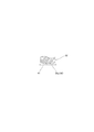
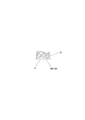
次に、ホルダ32について、更に図3及び図4を参酌して説明する。図1に示すように、ホルダ32はその下面側においてサンダベルト41をその内面側より支持するガイド面36が形成されており、ガイド面36は、図1におけるA−A断面図である図3において示されるように、サンダベルト41の進行方向に垂直な断面視においてサンダベルト41へ向かってR形状に形成されるR形状部36aを有している。さらに、ガイド面36は、図1におけるB−B断面図である図4において示されるように、サンダベルト41の進行方向に垂直な断面視において平面形状に形成される平面形状部36bを有している。すなわち本実施形態では、ホルダ32はベルトガイドとしての機能も併せ持つ構成となっている。
Next, the
次に、図5を参酌して、上述の実施形態に係る手持ち式ベルトサンダを使用してリング形状部品51の内周面51aを加工する場合について説明する。
Next, with reference to FIG. 5, a case where the inner
操作者は不図示のスイッチを操作してモータ12を運転させサンダベルト41を駆動させる。この状態でサンダベルト41をR形状部36aで支持される領域において、被加工面である内周面51aに押圧させると、サンダベルト41は内周面51aの形状に倣って変形し幅方向全域において摺接する状態となるが、ガイド面36のR形状部36aで支持されているため、R形状部36aの頭頂部領域において支持される領域で強く押圧されることとなる。
The operator operates a switch (not shown) to drive the
このため、サンダベルト41の幅方向両端部においては、サンダベルト41の形状復元力のみで内周面51aに押圧されるため、その押圧力は弱く、摺接による研磨砥粒の剥離およびベルト基材の損傷が早期に発生することはない。従って、サンダベルトの早期交換による作業効率の低下を防止することができる。
For this reason, since both ends of the
また、サンダベルト41はR形状部36aにより支持されるため、サンダベルト41の進行方向において内周面51aへの押圧力は不均一とならず、正確な加工を行うことが可能となる。
さらに、サンダベルト41はR形状部36aの頭頂部領域において支持される領域で強く押圧されるため、サンダベルト41の幅方向中央領域で主たる加工が行われることとなる。従って操作者は主たる加工領域の把握が容易になることから、正確な加工を作業性良く行うことが可能となる。
Further, since the
Furthermore, since the
なお、被加工面が平面である場合は、サンダベルト41を平面形状部36bで支持される領域において被加工面である平面に押圧させることで、従来の手持ち式ベルトサンダと同等の作業性で加工することができる。
When the surface to be processed is a flat surface, the
以上、本発明の好適な実施形態について説明したが、本発明の技術的範囲は上記実施形態の技術的範囲に限定さない。上記実施形態には、多様な変更又は改良を加えることが可能である。 The preferred embodiments of the present invention have been described above, but the technical scope of the present invention is not limited to the technical scope of the above embodiments. Various modifications or improvements can be added to the embodiment.
例えば、上記実施形態においては、R形状部36aと平面形状部36bを有するガイド面36をホルダ32の下面側に連続して形成している。しかしながら、上記実施形態で例示した構成は、本発明が取り得る一形態を示したに過ぎない。例えば、ホルダ32の上面側を平面形状、下面側をR形状に形成し、被加工面の形状によりいずれかのガイド面を選択できるように構成しても良い。また、上記実施形態においてはガイド面はホルダ32に一体的に形成したが、ガイド面を有するベルトガイドとしてホルダ32とは別体として装備することも可能である。
For example, in the above embodiment, the
その様な変更又は改良を加えた形態も本発明の技術的範囲に含まれることが、特許請求の範囲の記載から明らかである。 It is apparent from the scope of the claims that the embodiments added with such changes or improvements are also included in the technical scope of the present invention.
10 本体部、11 ハウジング、12 モータ、20 駆動伝動部、21 駆動プーリ、22 従動プーリ、30 アーム部、31 連結部材、31a 装着穴、32 ホルダ、33 係止爪、34 軸部、35 スプリング、36 ガイド面、36a R形状部、36b 平面形状部、41 サンダベルト、51 リング形状部材、51a 内周面
DESCRIPTION OF
Claims (1)
前記駆動プーリと離間して回動自在に設置された従動プーリと、
前記駆動プーリと前記従動プーリとの間に張架された無端のサンダベルトと、
前記サンダベルトの内面側に装備され前記サンダベルトを支持するガイド面を有するベルトガイドと、を備える手持ち式ベルトサンダにおいて、
前記ガイド面は、前記サンダベルトの進行方向に垂直な断面視において前記サンダベルトへ向かってR形状に形成されるR形状部を備えることを特徴とする手持ち式ベルトサンダ。 A drive pulley that is rotationally driven by a drive source;
A driven pulley installed to be rotatable apart from the drive pulley;
An endless sander belt stretched between the drive pulley and the driven pulley;
In a hand-held belt sander comprising a belt guide that is provided on the inner surface side of the sander belt and has a guide surface that supports the sander belt,
The hand-held belt sander, wherein the guide surface includes an R-shaped portion formed in an R shape toward the sander belt in a cross-sectional view perpendicular to the traveling direction of the sander belt.
Priority Applications (1)
| Application Number | Priority Date | Filing Date | Title |
|---|---|---|---|
| JP2011031604A JP2012166329A (en) | 2011-02-17 | 2011-02-17 | Handheld belt sander |
Applications Claiming Priority (1)
| Application Number | Priority Date | Filing Date | Title |
|---|---|---|---|
| JP2011031604A JP2012166329A (en) | 2011-02-17 | 2011-02-17 | Handheld belt sander |
Publications (1)
| Publication Number | Publication Date |
|---|---|
| JP2012166329A true JP2012166329A (en) | 2012-09-06 |
Family
ID=46970996
Family Applications (1)
| Application Number | Title | Priority Date | Filing Date |
|---|---|---|---|
| JP2011031604A Withdrawn JP2012166329A (en) | 2011-02-17 | 2011-02-17 | Handheld belt sander |
Country Status (1)
| Country | Link |
|---|---|
| JP (1) | JP2012166329A (en) |
-
2011
- 2011-02-17 JP JP2011031604A patent/JP2012166329A/en not_active Withdrawn
Similar Documents
| Publication | Publication Date | Title |
|---|---|---|
| US10906108B2 (en) | Blade accessory with guide | |
| US20020066190A1 (en) | Guide means for a circular saw | |
| JP2011240449A (en) | Wire saw | |
| JP2012106471A (en) | Scriber holder | |
| US9205502B2 (en) | Reciprocating saw | |
| JP2012166329A (en) | Handheld belt sander | |
| US10293419B2 (en) | Straight cutting oscillating blade | |
| CN105642927B (en) | A kind of high finishing tool, high ray machine and metal-back bloom processing method | |
| CN203901023U (en) | Blade grinding device | |
| JP2019018263A (en) | Cutting apparatus and cutting method | |
| KR20120001182A (en) | Chainsaw | |
| JP2015037817A (en) | Double-head side surface milling machine | |
| JP5105161B2 (en) | Electric tool | |
| JP6228022B2 (en) | Electric tool base seat, electric tool equipped with base seat | |
| CN103538161B (en) | Machining tool | |
| US10286467B2 (en) | Tool device | |
| CN203092509U (en) | Accessory clamping mechanism and power tool with accessory clamping mechanism | |
| ATE477886T1 (en) | DRESSING TOOL FOR A GRINDSTONE | |
| JP5433489B2 (en) | Cutting blade position adjusting jig and cutting blade position adjusting method | |
| KR101417339B1 (en) | Apparatus for fixing insert tip on slotting machine | |
| KR101315997B1 (en) | Jig for fixing grinding member | |
| CN214922358U (en) | Clamping mechanism and cutting device | |
| CN220575512U (en) | Grinding machine assembly for sand paper | |
| JP5295051B2 (en) | Deburring machine | |
| JP2012218096A (en) | Cutter |
Legal Events
| Date | Code | Title | Description |
|---|---|---|---|
| A300 | Withdrawal of application because of no request for examination |
Free format text: JAPANESE INTERMEDIATE CODE: A300 Effective date: 20140513 |