JP2012166325A - Joint for manipulator - Google Patents
Joint for manipulator Download PDFInfo
- Publication number
- JP2012166325A JP2012166325A JP2011031271A JP2011031271A JP2012166325A JP 2012166325 A JP2012166325 A JP 2012166325A JP 2011031271 A JP2011031271 A JP 2011031271A JP 2011031271 A JP2011031271 A JP 2011031271A JP 2012166325 A JP2012166325 A JP 2012166325A
- Authority
- JP
- Japan
- Prior art keywords
- housing
- arm
- mounting hole
- joint
- unit mounting
- Prior art date
- Legal status (The legal status is an assumption and is not a legal conclusion. Google has not performed a legal analysis and makes no representation as to the accuracy of the status listed.)
- Withdrawn
Links
Images


Landscapes
- Manipulator (AREA)
- Mounting Of Bearings Or Others (AREA)
- Rolling Contact Bearings (AREA)
Abstract
【課題】作業効率の向上と組立てコストの低減化を図り、高精度のマニピュレータ動作を行うことができる小型のマニピュレータ用関節部を提供する。
【解決手段】軸受ユニット8のハウジング14には、ハウジング14の回転中心O2を通り径方向に延びる直線と略直交する平坦面14bが形成され、回動アームのユニット装着孔7には、外径側に窪む係止凹部7aが形成されている。ハウジング14の平坦面14bとユニット装着孔7の係止凹部7aとの間には、板状の係止部材30が設けられて、ハウジング14がユニット装着孔7に回転不能に固定される。
【選択図】図3The present invention provides a small manipulator joint capable of improving the working efficiency and reducing the assembly cost and capable of performing a highly accurate manipulator operation.
A housing 14 of a bearing unit 8 is formed with a flat surface 14b substantially orthogonal to a straight line extending in the radial direction through the rotation center O2 of the housing 14, and the unit mounting hole 7 of the rotating arm has an outer diameter. A locking recess 7a that is recessed to the side is formed. A plate-like locking member 30 is provided between the flat surface 14 b of the housing 14 and the locking recess 7 a of the unit mounting hole 7, and the housing 14 is fixed to the unit mounting hole 7 so as not to rotate.
[Selection] Figure 3
Description
本発明は、人間の指に似た動作を機械的に行うマニピュレータにおいて複数のアームを回動自在に連結するマニピュレータ用関節部に関する。 The present invention relates to a joint unit for a manipulator that rotatably connects a plurality of arms in a manipulator that mechanically performs an operation similar to a human finger.
産業機械の加工ライン、組立てライン等では、省力化、自動化のために種々のロボットアームを使用している。
ロボットアームは、複数のアームを関節部を介して連結した装置であり、関節部の構成部材として、複列の転がり軸受を組み込んだ装置が知られている(例えば、特許文献1)。
In the processing line and assembly line of industrial machines, various robot arms are used for labor saving and automation.
A robot arm is a device in which a plurality of arms are connected via a joint, and a device incorporating a double-row rolling bearing as a component of the joint is known (for example, Patent Document 1).
特許文献1の関節部に組み込まれている転がり軸受は、軸受の軸方向断面幅と半径方向断面高さの比を所定値に設定することで内輪及び外輪の厚さ寸法を増大させ、高剛性、高回転精度、低トルク、低発熱を図っている。 The rolling bearing incorporated in the joint portion of Patent Document 1 increases the thickness dimension of the inner ring and the outer ring by setting the ratio of the axial sectional width and the radial sectional height of the bearing to a predetermined value, and has high rigidity. High rotational accuracy, low torque, and low heat generation.
ところで、ロボットアームのような大型の装置ではなく、人間の指に似た動作を機械的に行うマニピュレータの技術開発も行われているが、マニピュレータの関節部に、前述した特許文献1に記載のロボットアーム用転がり軸受を採用するのは難しい。
すなわち、内輪及び外輪の厚さ寸法を増大させる特許文献1の転がり軸受の諸元を適用するとマニピュレータ用の転がり軸受が大型になってしまうので、小型化が必要なマニピュレータ用関節部に採用するのは困難である。
By the way, technical development of a manipulator that mechanically performs an operation similar to a human finger, not a large-sized device such as a robot arm, is also being performed. It is difficult to adopt rolling bearings for robot arms.
That is, when the specifications of the rolling bearing of Patent Document 1 that increases the thickness dimension of the inner ring and the outer ring are applied, the rolling bearing for the manipulator becomes large, so that it is adopted for a joint part for manipulator that requires downsizing. It is difficult.
一方、特許文献2には、マニピュレータ用関節部が開示されている。この特許文献2に記載のマニピュレータ用関節部は、転がり軸受のハウジングと回動アームとの取り付けについて具体的な記載はないが、接着剤で固定されていると考えられる。 On the other hand, Patent Literature 2 discloses a manipulator joint. Although the joint part for manipulators described in Patent Document 2 has no specific description about the attachment of the housing and the rotating arm of the rolling bearing, it is considered that it is fixed with an adhesive.
しかしながら、接着剤を使用した場合、その雰囲気温度や使用条件によってはアウトガスを発生することが知られており、人に身近な存在であるパートナーロボットや家事ロボットに使用される際の妨げになることが想定される。 However, it is known that when an adhesive is used, outgas may be generated depending on the ambient temperature and usage conditions, which may hinder the use of the robot for partner robots and household robots that are close to people. Is assumed.
また、このマニピュレータ用関節部に不具合が生じてしまった場合、関節部から転がり軸受単体を取り外すことは難しく、アーム全体を交換することになるため、作業効率とコストの面からみると改善の余地があった。 In addition, if a failure occurs in the joint for this manipulator, it is difficult to remove the rolling bearing alone from the joint, and the entire arm must be replaced, so there is room for improvement in terms of work efficiency and cost. was there.
そこで、本発明は、組立てが容易な転がり軸受を採用することで、作業効率の向上と組立てコストの低減化を図ることができるとともに、環境に優しく且つ高精度のマニピュレータ動作を行うことができる小型のマニピュレータ用関節部を提供することを目的としている。 Therefore, the present invention employs a rolling bearing that is easy to assemble, thereby improving work efficiency and reducing assembly costs, and is capable of performing an environment-friendly and highly accurate manipulator operation. It aims at providing the joint part for manipulators.
上記目的は以下の構成により達成される。
(1)基部アーム及び回動アームの端部同士を連結し、前記端部を支点として前記回動アームを回動させるマニピュレータ用関節部であって、
前記基部アームの前記端部に配設される関節軸と、
前記回動アームの前記端部に形成されたユニット装着孔に取り付けられる円筒状のハウジングと、該ハウジングの内部に配設され前記回動アームを前記関節軸に対して回転自在に支持する複列の転がり軸受と、を有する軸受ユニットと、を備え、
前記ハウジングの外周面には、該ハウジングの回転中心を通り径方向に延びる直線と略直交する平坦面が形成されており、
前記ユニット装着孔には、外径側に窪むように係止凹部が形成されており、
前記ハウジングの平坦面と前記ユニット装着孔の係止凹部との間には、板状の係止部材が設けられ、前記ハウジングが前記ユニット装着孔に回転不能に固定されることを特徴とするマニピュレータ用関節部。
(2)前記軸受ユニットは、前記複列の転がり軸受の内輪に嵌合され、前記関節軸が同軸上に固定されるスリーブをさらに備えていることを特徴とする(1)記載のマニピュレータ用関節部。
(3)前記回動アームは、前記転がり軸受の内輪の材料及び外輪の材料よりも線膨張係数の大きな材料から構成され、
前記関節軸は、前記スリーブの材料よりも線膨張係数の大きな材料から構成されていることを特徴とする(2)に記載のマニピュレータ用関節部。
The above object is achieved by the following configuration.
(1) A joint part for a manipulator that connects ends of the base arm and the rotation arm and rotates the rotation arm with the end as a fulcrum,
A joint shaft disposed at the end of the base arm;
A cylindrical housing attached to a unit mounting hole formed at the end of the rotating arm, and a double row disposed inside the housing and rotatably supporting the rotating arm with respect to the joint shaft A rolling bearing, and a bearing unit having
On the outer peripheral surface of the housing, a flat surface that is substantially orthogonal to a straight line extending in the radial direction through the rotation center of the housing is formed,
In the unit mounting hole, a locking recess is formed so as to be recessed on the outer diameter side,
A plate-like locking member is provided between the flat surface of the housing and the locking recess of the unit mounting hole, and the housing is fixed to the unit mounting hole in a non-rotatable manner. For joints.
(2) The joint for manipulator according to (1), wherein the bearing unit further includes a sleeve that is fitted to an inner ring of the double row rolling bearing, and the joint shaft is coaxially fixed. Department.
(3) The rotating arm is made of a material having a larger linear expansion coefficient than the material of the inner ring and the material of the outer ring of the rolling bearing,
The joint part for manipulators according to (2), wherein the joint shaft is made of a material having a larger linear expansion coefficient than the material of the sleeve.
本発明によれば、ハウジングの平坦面とユニット装着孔の係止凹部との間には、板状の係止部材を設けることで、ハウジングをユニット装着孔に回転不能に固定することができる。これにより、接着剤固定に比べて環境に優しく低コストなマニピュレータ用関節部を構成することができる。また、過大な荷重や衝撃荷重が加わっても円滑に可動することができるとともに、軸受ユニットは係止部材だけで回動アームに固定されるので、故障時又はメンテナンス時の軸受交換が容易となる。 According to the present invention, the housing can be fixed to the unit mounting hole in a non-rotatable manner by providing the plate-shaped locking member between the flat surface of the housing and the locking recess of the unit mounting hole. Thereby, the joint part for manipulators which is environmentally friendly and low-cost compared with adhesive fixing can be comprised. In addition, it can move smoothly even when an excessive load or impact load is applied, and the bearing unit is fixed to the rotating arm only by the locking member, so that it is easy to replace the bearing at the time of failure or maintenance. .
以下、本発明のマニピュレータ用関節部の一実施形態を、図1〜図5を参照しながら詳細に説明する。 Hereinafter, an embodiment of a joint part for a manipulator according to the present invention will be described in detail with reference to FIGS.
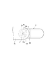
マニピュレータ1は、図1に示すように、中空円筒形状の第1アーム2と、小径部3a及び大径部3bからなる中空円筒形状の第2アーム3と、先端部を球面形状とした中空円筒形状の第3アーム4と、第1アーム2の先端部及び第2アーム3の後端部を連結している第1関節部5と、第2アーム3の先端部及び第3アーム4の後端部を連結している第2関節部6とを備えている。
As shown in FIG. 1, the manipulator 1 includes a hollow cylindrical first arm 2, a hollow cylindrical second arm 3 composed of a
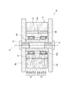
第2アーム3及び第3アーム4を連結している第2関節部6は、図2及び図3に示すように、第3アーム4の後端部に形成したユニット装着孔7に嵌合する軸受ユニット8と、この軸受ユニット8の回転中心P位置に装着され、第2アーム3の先端部に形成した連結板3cに配設される連結ネジ9と、を備え、軸受ユニット8の外周に掛け渡された駆動ワイヤ10を駆動力伝達装置11で引っ張ることにより、軸受ユニット8を介して第3アーム4を連結ネジ9(回転中心P)回りに回動可能に構成されている。
The
ユニット装着孔7は、図4に示すように、第3アーム4の長手方向に対して直交する方向に略円形に開口するとともに、略円形の開口の一部が外径側に窪むように係止凹部7aが形成されている。係止凹部7aは、ユニット装着孔7の中心線O1に沿って一端側から他端側まで軸方向に伸びている。
As shown in FIG. 4, the
図2に戻って、軸受ユニット8は、2つの玉軸受12,13と、単一のハウジング14と、単一のスリーブ15とを一体化した部品である。
Returning to FIG. 2, the
2つの玉軸受のうち一方の玉軸受12は、外輪12a及び内輪12bと、外輪12aの軌道溝及び内輪12bの軌道溝間に転動自在に配設された多数の玉12cと、外輪12a及び内輪12bの間の軸方向の両端部を閉塞する環状シール体12dとを備えている。また、他方の玉軸受13も、一方の玉軸受12と同一形状の外輪13a及び内輪13bと、外輪13aの軌道溝及び内輪13bの軌道溝間に転動自在に配設された多数の玉13cと、外輪13a及び内輪13bの間の軸方向の両端部を閉塞する環状シール体13dとを備えている。
Of the two ball bearings, one ball bearing 12 includes an
外輪12a,13a、内輪12b,13b及び玉12c,13cの材料は、標準的な使用条件では軸受鋼(例えば、SUJ2、SUJ3など)とするが、使用環境に応じて、耐食材料であるステンレス系材料(例えば、SUS440C等のマルテンサイト系ステンレス鋼材やSUS304等のオーステナイト系ステンレス鋼材、SUS630等の析出硬化系ステンレス鋼材など)、チタン合金やセラミック系材料(例えば、Si3 N4 、SiC、Al2 O3 、ZrO2 等)を採用してもよい。
The material of the
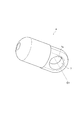
ハウジング14は、2つの玉軸受12,13の外輪12a,13aを内嵌し、第3アーム4のユニット装着孔7の内周面に嵌合する円筒形状の部材である。より具体的に、ハウジング14は、その内部が延出方向に沿って中空を成す円筒状に構成されており、その内周面の略中央部に周方向に沿って環状凸部14aが設けられている。また、外周面には、図5に示すように、ハウジング14の回転中心O2を通り径方向に延びる直線Lと略直交する平坦面14bが形成される。この平坦面14bは、軸方向一端部から他端部に亘って延びており、このハウジング14を軸方向から見ると略D字形状の外観をなしている。
The
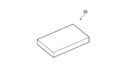
このハウジング14を第3アーム4のユニット装着孔7に、平坦面14bが係止凹部7aと径方向で対向するように周方向の位置をあわせて配置すると、平坦面14bと係止凹部7aとにより、軸方向に延びる略四角柱状の空間が形成される。この空間には、図6に示す板状の係止部材30が圧入されている。
When the
スリーブ15は、玉軸受12,13の内輪12b,13bの内周部に嵌合する円筒形状の部材であり、内周面には連結ネジ9が螺合する雌ネジ部が形成され、外周面には、軸方向一方側(図2中下側)に外径側に突出する鍔部15aが形成されている。なお、鍔部15aは必ずしも設ける必要はないが、鍔部15aを設けることで玉軸受13を位置決めすることができる。
The
第2アーム3及び第3アーム4は、その材料として、軸受12、13の外輪12a,13a及び内輪12b,13bの材料よりも線膨張係数の大きな材料が使用される。また、連結ネジ9はスリーブ15の材料よりも線膨張係数の大きな材料が使用される。これにより、運転中の軸受12、13から発生する熱により軸受12、13の内外輪12b,13b、12a,13aが膨張しても剛性を確保することができる。
The second arm 3 and the
駆動ワイヤ10は、その先端部が第3アーム4の外周に固定されたワイヤ止め部材16に係止されているとともに、第2アーム3を構成する大径部3bの内部空間を通過し、小径部3aの内部空間に配置したプーリ17に係合した後に、第1アーム2の内部空間に延在し、第1アーム2の外部に配置した駆動力伝達装置11に連結されている。
The
次にこのように構成された第2関節部6の組み付け方法について説明する。
まず、2つの軸受12、13の外輪12a,13a間に環状凸部14aを介在させて、ハウジング14の内周面に各外輪12a,13aを圧入固定した状態で、軸方向一方側(図2中下側)から内輪12b,13bにスリーブ15を内嵌させて軸受ユニット8を組み付ける。このとき、軸受13の内輪13bは、スリーブ15の鍔部15aに当接する。
Next, a method for assembling the second
First, an annular
そして、第3アーム4のユニット装着孔7に軸受ユニット8を軸方向一方側から挿入する。このとき、ハウジング14の平坦面14bと、ユニット装着孔7の係止凹部7aとが径方向で対向するように周方向位置をあわせて配置する。この状態で、平坦面14bと係止凹部7aとにより形成された略四角柱状の空間に係止部材30を圧入することで、ユニット装着孔7にハウジング14が回転不能に固定される。即ち、第3アーム4に軸受ユニット8が固定される。
Then, the
続いて、第2アーム3の連結板3c間に第3アーム4を配置し、連結ネジ9を締め付けることで、連結ネジ9が軸受ユニット8のスリーブ15に形成された雌ネジに螺合し、第2アーム3に対し第3アーム4が回動可能に固定される。
Subsequently, the
第1アーム2及び第2アーム3を連結している第1関節部5も、詳細には説明しないが、第2アーム3の小径部3aに形成したユニット装着孔に嵌合する2つの玉軸受12,13を内蔵した軸受ユニット18と、この軸受ユニット18の回転中心位置に装着され、第1アーム2の一端に形成した連結板2cに配設される連結ネジ19と、を備え、軸受ユニット18の外周に掛け渡された駆動ワイヤ20を前述した駆動力伝達装置11で引っ張ることにより、軸受ユニット18を介して第2アーム3を連結ネジ19回りに回動可能に構成されている。なお、第1関節部5についても第2関節部6と同様に、第2アーム3のユニット装着孔に軸受ユニット18のハウジングを係止部材で固定するように構成してもよい。
The first joint 5 that connects the first arm 2 and the second arm 3 is not described in detail, but two ball bearings that fit into a unit mounting hole formed in the small-
ここで、図1に示すマニピュレータ1には、詳細には図示しないが、第1関節部5に、駆動ワイヤ20の引張力により軸受ユニット18が回動する方向に対して軸受ユニット18を逆方向(図1の符号Y1で示す方向)に回動させようとする力を発生させる反力部材(例えばバネ等の弾性部材)が内蔵されているとともに、第2関節部6にも、駆動ワイヤ10の引張力により軸受ユニット8が回動する方向に対して軸受ユニット8を逆方向(図1の符号Y2で示す方向)に回動させようとする力を発生させる反力部材(例えばバネ等の弾性部材)が内蔵されている。
Here, although not shown in detail in the manipulator 1 shown in FIG. 1, the bearing
上記構成のマニピュレータ1は、駆動力伝達装置11の駆動により駆動ワイヤ20に引張力を付与すると、軸受ユニット18の2つの玉軸受12,13に支持されたハウジング14がスムーズに連結ネジ19回りに回動するので、第2アーム3が、図1に示すY1方向に対して逆方向に所定角度まで高精度に回動する。また、駆動力伝達装置11の駆動により駆動ワイヤ10に引張力を付与すると、軸受ユニット8の2つの玉軸受12,13に支持されたハウジング14がスムーズに連結ネジ9回りに回動するので、第3アーム4が、図1に示すY2方向に対して逆方向に所定角度まで高精度に回動する。また、駆動力伝達装置11の駆動を解除して駆動ワイヤ20を所定量だけ戻すと、第2アーム3は反力部材の力によりY1方向に所定角度まで回動する。さらに、駆動力伝達装置11の駆動を解除して駆動ワイヤ10を所定量だけ戻すと、第2アーム3は反力部材の力によりY2方向に所定角度まで回動する。
When the manipulator 1 configured as described above applies a tensile force to the
以上説明したように、本実施形によれば、第3アーム4と軸受ユニット8を係止部材30で固定することができるので、接着剤固定に比べて環境に優しく低コストなマニピュレータ用関節部を構成することができる。
As described above, according to the present embodiment, since the
また、過大な荷重や衝撃荷重が加わっても円滑に可動することができるとともに、軸受ユニットは係止部材30だけで回動アームに固定されるので、故障時又はメンテナンス時の軸受交換が容易となる。さらに、ハウジング14と係止部材30との係合面は平坦面なので、ハウジング14の加工が容易である。
In addition, the bearing unit can be moved smoothly even if an excessive load or impact load is applied, and the bearing unit is fixed to the rotating arm only by the locking
また、軸受ユニット8は、単一のハウジング14と単一のスリーブ15との間に2つの玉軸受12,13が組み込まれた部材であり、マニピュレータ1の組立て作業時には玉軸受12,13の難しい取付けが不要となるので、さらに組立てコストの低減化を図ることができる。また、故障時又はメンテナンス時の軸受12、13の交換が容易である。そのほか、ハウジング14自体をユニット装着孔7に圧入する場合に比べて交差の管理が容易である。
Further, the
なお、上記各実施形態の関節部で使用した転がり軸受は、外輪、内輪、転動体、保持器等の構成は、上記各態様の実施の形態に例示したものに限定されるものではなく、本発明の要旨を逸脱しない範囲において、適宜変更可能である。 The rolling bearings used in the joint portions of the above embodiments are not limited to the configurations of the outer ring, the inner ring, the rolling elements, the cage, etc., as illustrated in the embodiments of the above embodiments. Changes can be made as appropriate without departing from the scope of the invention.
例えば、係止凹部7aと係止部材30の形状は上記実施形態に限定されず、係止凹部7aは、ハウジング14の平坦面14bと対向する底面が軸方向一端側から他端側に向かって傾斜する傾斜面で構成され、係止部材30係止凹部7aの傾斜面に対応するように傾斜面を有するように構成してもよい。
For example, the shape of the
1 マニピュレータ
2 第1アーム(基部アーム)
3 第2アーム(基部アーム、回動アーム)
4 第3アーム(回動アーム)
5 第1関節部(マニピュレータ用関節部)
6 第2関節部(マニピュレータ用関節部)
7 ユニット装着孔
7a 係止凹部
8、18 軸受ユニット
9、19 連結ネジ(関節軸)
14 ハウジング
14b 平坦面
15 スリーブ
30 係止部材
1 Manipulator 2 First arm (base arm)
3 Second arm (base arm, pivot arm)
4 Third arm (rotating arm)
5 First joint (manipulator joint)
6 Second joint (manipulator joint)
7
14
Claims (3)
前記基部アームの前記端部に配設される関節軸と、
前記回動アームの前記端部に形成されたユニット装着孔に取り付けられる円筒状のハウジングと、該ハウジングの内部に配設され前記回動アームを前記関節軸に対して回転自在に支持する複列の転がり軸受と、を有する軸受ユニットと、を備え、
前記ハウジングの外周面には、該ハウジングの回転中心を通り径方向に延びる直線と略直交する平坦面が形成されており、
前記ユニット装着孔には、外径側に窪むように係止凹部が形成されており、
前記ハウジングの平坦面と前記ユニット装着孔の係止凹部との間には、板状の係止部材が設けられ、前記ハウジングが前記ユニット装着孔に回転不能に固定されることを特徴とするマニピュレータ用関節部。 A joint part for a manipulator that connects ends of the base arm and the rotating arm and rotates the rotating arm with the end as a fulcrum,
A joint shaft disposed at the end of the base arm;
A cylindrical housing attached to a unit mounting hole formed at the end of the rotating arm, and a double row disposed inside the housing and rotatably supporting the rotating arm with respect to the joint shaft A rolling bearing, and a bearing unit having
On the outer peripheral surface of the housing, a flat surface that is substantially orthogonal to a straight line extending in the radial direction through the rotation center of the housing is formed,
In the unit mounting hole, a locking recess is formed so as to be recessed on the outer diameter side,
A plate-like locking member is provided between the flat surface of the housing and the locking recess of the unit mounting hole, and the housing is fixed to the unit mounting hole in a non-rotatable manner. For joints.
前記関節軸は、前記スリーブの材料よりも線膨張係数の大きな材料から構成されていることを特徴とする請求項2に記載のマニピュレータ用関節部。 The rotating arm is made of a material having a larger linear expansion coefficient than the material of the inner ring and the material of the outer ring of the rolling bearing,
The joint part for a manipulator according to claim 2, wherein the joint shaft is made of a material having a larger linear expansion coefficient than the material of the sleeve.
Priority Applications (1)
| Application Number | Priority Date | Filing Date | Title |
|---|---|---|---|
| JP2011031271A JP2012166325A (en) | 2011-02-16 | 2011-02-16 | Joint for manipulator |
Applications Claiming Priority (1)
| Application Number | Priority Date | Filing Date | Title |
|---|---|---|---|
| JP2011031271A JP2012166325A (en) | 2011-02-16 | 2011-02-16 | Joint for manipulator |
Publications (1)
| Publication Number | Publication Date |
|---|---|
| JP2012166325A true JP2012166325A (en) | 2012-09-06 |
Family
ID=46970994
Family Applications (1)
| Application Number | Title | Priority Date | Filing Date |
|---|---|---|---|
| JP2011031271A Withdrawn JP2012166325A (en) | 2011-02-16 | 2011-02-16 | Joint for manipulator |
Country Status (1)
| Country | Link |
|---|---|
| JP (1) | JP2012166325A (en) |
Cited By (1)
| Publication number | Priority date | Publication date | Assignee | Title |
|---|---|---|---|---|
| CN110382174A (en) * | 2017-01-10 | 2019-10-25 | 直觉机器人有限公司 | An apparatus for performing emotional gestures to interact with a user |
-
2011
- 2011-02-16 JP JP2011031271A patent/JP2012166325A/en not_active Withdrawn
Cited By (3)
| Publication number | Priority date | Publication date | Assignee | Title |
|---|---|---|---|---|
| CN110382174A (en) * | 2017-01-10 | 2019-10-25 | 直觉机器人有限公司 | An apparatus for performing emotional gestures to interact with a user |
| JP2020504027A (en) * | 2017-01-10 | 2020-02-06 | インチュイション ロボティクス、リミテッド | Device for performing emotional gestures and interacting with users |
| US12186885B2 (en) | 2017-01-10 | 2025-01-07 | Intuition Robotics, Ltd | Device for performing emotional gestures to interact with a user |
Similar Documents
| Publication | Publication Date | Title |
|---|---|---|
| JP6289973B2 (en) | Parallel link mechanism and link actuator | |
| JP2012115927A (en) | Joint for manipulator | |
| CN103906947B (en) | Parallel linkages, constant velocity joints and link action devices | |
| CN102441894A (en) | Arm component of robot | |
| CN104024693B (en) | Link operation device | |
| CN112236607B (en) | Linkage Actuator | |
| JP2007536473A5 (en) | ||
| CN113597523A (en) | Parallel linkage and linkage actuating device | |
| JP5487446B2 (en) | Manipulator joint | |
| JP5434483B2 (en) | Robot arm | |
| JP5911697B2 (en) | Parallel link mechanism, constant velocity universal joint, and link actuator | |
| JP5593654B2 (en) | Robot joint | |
| JP2012166325A (en) | Joint for manipulator | |
| JP2010000587A (en) | Joint section for manipulator | |
| JP5625348B2 (en) | manipulator | |
| JP2016109232A (en) | Bearing unit | |
| JP2012096298A (en) | Manipulator joint | |
| JP5293263B2 (en) | Bearing unit for joint part of manipulator and joint part of manipulator | |
| JP2012077768A (en) | Joint part for manipulator | |
| JP5138616B2 (en) | Ball screw shaft support structure | |
| JP5412870B2 (en) | Robot finger | |
| JP5187232B2 (en) | Universal joint | |
| JP2012172764A (en) | Spherical bearing | |
| WO2015182556A1 (en) | Parallel link mechanism and link operation device | |
| CN116025679B (en) | Screw assembly and robot |
Legal Events
| Date | Code | Title | Description |
|---|---|---|---|
| RD04 | Notification of resignation of power of attorney |
Free format text: JAPANESE INTERMEDIATE CODE: A7424 Effective date: 20140210 |
|
| A300 | Withdrawal of application because of no request for examination |
Free format text: JAPANESE INTERMEDIATE CODE: A300 Effective date: 20140513 |