JP2012166316A - Cutting apparatus - Google Patents
Cutting apparatus Download PDFInfo
- Publication number
- JP2012166316A JP2012166316A JP2011030061A JP2011030061A JP2012166316A JP 2012166316 A JP2012166316 A JP 2012166316A JP 2011030061 A JP2011030061 A JP 2011030061A JP 2011030061 A JP2011030061 A JP 2011030061A JP 2012166316 A JP2012166316 A JP 2012166316A
- Authority
- JP
- Japan
- Prior art keywords
- blade
- fixed blade
- cutter head
- support surface
- cutting
- Prior art date
- Legal status (The legal status is an assumption and is not a legal conclusion. Google has not performed a legal analysis and makes no representation as to the accuracy of the status listed.)
- Granted
Links
- 238000005520 cutting process Methods 0.000 title claims abstract description 122
- 239000000463 material Substances 0.000 claims abstract description 52
- 230000007246 mechanism Effects 0.000 claims description 28
- 238000001514 detection method Methods 0.000 claims description 11
- 238000000926 separation method Methods 0.000 claims description 6
- 239000004744 fabric Substances 0.000 abstract description 62
- 230000004044 response Effects 0.000 description 4
- 230000009471 action Effects 0.000 description 2
- 238000013459 approach Methods 0.000 description 2
- 238000006073 displacement reaction Methods 0.000 description 2
- 230000005684 electric field Effects 0.000 description 2
- 238000010008 shearing Methods 0.000 description 2
- 230000037303 wrinkles Effects 0.000 description 2
- 238000006243 chemical reaction Methods 0.000 description 1
- 238000012840 feeding operation Methods 0.000 description 1
- 210000004209 hair Anatomy 0.000 description 1
- 239000010985 leather Substances 0.000 description 1
- 238000004519 manufacturing process Methods 0.000 description 1
- 230000003287 optical effect Effects 0.000 description 1
- 239000000123 paper Substances 0.000 description 1
- 238000003825 pressing Methods 0.000 description 1
- 239000011347 resin Substances 0.000 description 1
- 229920005989 resin Polymers 0.000 description 1
Images

Classifications
-
- B—PERFORMING OPERATIONS; TRANSPORTING
- B26—HAND CUTTING TOOLS; CUTTING; SEVERING
- B26D—CUTTING; DETAILS COMMON TO MACHINES FOR PERFORATING, PUNCHING, CUTTING-OUT, STAMPING-OUT OR SEVERING
- B26D1/00—Cutting through work characterised by the nature or movement of the cutting member or particular materials not otherwise provided for; Apparatus or machines therefor; Cutting members therefor
- B26D1/01—Cutting through work characterised by the nature or movement of the cutting member or particular materials not otherwise provided for; Apparatus or machines therefor; Cutting members therefor involving a cutting member which does not travel with the work
- B26D1/04—Cutting through work characterised by the nature or movement of the cutting member or particular materials not otherwise provided for; Apparatus or machines therefor; Cutting members therefor involving a cutting member which does not travel with the work having a linearly-movable cutting member
- B26D1/045—Cutting through work characterised by the nature or movement of the cutting member or particular materials not otherwise provided for; Apparatus or machines therefor; Cutting members therefor involving a cutting member which does not travel with the work having a linearly-movable cutting member for thin material, e.g. for sheets, strips or the like
-
- B—PERFORMING OPERATIONS; TRANSPORTING
- B26—HAND CUTTING TOOLS; CUTTING; SEVERING
- B26D—CUTTING; DETAILS COMMON TO MACHINES FOR PERFORATING, PUNCHING, CUTTING-OUT, STAMPING-OUT OR SEVERING
- B26D1/00—Cutting through work characterised by the nature or movement of the cutting member or particular materials not otherwise provided for; Apparatus or machines therefor; Cutting members therefor
- B26D1/01—Cutting through work characterised by the nature or movement of the cutting member or particular materials not otherwise provided for; Apparatus or machines therefor; Cutting members therefor involving a cutting member which does not travel with the work
- B26D1/12—Cutting through work characterised by the nature or movement of the cutting member or particular materials not otherwise provided for; Apparatus or machines therefor; Cutting members therefor involving a cutting member which does not travel with the work having a cutting member moving about an axis
- B26D1/14—Cutting through work characterised by the nature or movement of the cutting member or particular materials not otherwise provided for; Apparatus or machines therefor; Cutting members therefor involving a cutting member which does not travel with the work having a cutting member moving about an axis with a circular cutting member, e.g. disc cutter
- B26D1/22—Cutting through work characterised by the nature or movement of the cutting member or particular materials not otherwise provided for; Apparatus or machines therefor; Cutting members therefor involving a cutting member which does not travel with the work having a cutting member moving about an axis with a circular cutting member, e.g. disc cutter coacting with a movable member, e.g. a roller
- B26D1/225—Cutting through work characterised by the nature or movement of the cutting member or particular materials not otherwise provided for; Apparatus or machines therefor; Cutting members therefor involving a cutting member which does not travel with the work having a cutting member moving about an axis with a circular cutting member, e.g. disc cutter coacting with a movable member, e.g. a roller for thin material, e.g. for sheets, strips or the like
-
- B—PERFORMING OPERATIONS; TRANSPORTING
- B26—HAND CUTTING TOOLS; CUTTING; SEVERING
- B26D—CUTTING; DETAILS COMMON TO MACHINES FOR PERFORATING, PUNCHING, CUTTING-OUT, STAMPING-OUT OR SEVERING
- B26D7/00—Details of apparatus for cutting, cutting-out, stamping-out, punching, perforating, or severing by means other than cutting
- B26D7/01—Means for holding or positioning work
- B26D7/015—Means for holding or positioning work for sheet material or piles of sheets
-
- B—PERFORMING OPERATIONS; TRANSPORTING
- B26—HAND CUTTING TOOLS; CUTTING; SEVERING
- B26D—CUTTING; DETAILS COMMON TO MACHINES FOR PERFORATING, PUNCHING, CUTTING-OUT, STAMPING-OUT OR SEVERING
- B26D7/00—Details of apparatus for cutting, cutting-out, stamping-out, punching, perforating, or severing by means other than cutting
- B26D7/22—Safety devices specially adapted for cutting machines
-
- B—PERFORMING OPERATIONS; TRANSPORTING
- B26—HAND CUTTING TOOLS; CUTTING; SEVERING
- B26F—PERFORATING; PUNCHING; CUTTING-OUT; STAMPING-OUT; SEVERING BY MEANS OTHER THAN CUTTING
- B26F1/00—Perforating; Punching; Cutting-out; Stamping-out; Apparatus therefor
- B26F1/38—Cutting-out; Stamping-out
- B26F1/3806—Cutting-out; Stamping-out wherein relative movements of tool head and work during cutting have a component tangential to the work surface
- B26F1/3813—Cutting-out; Stamping-out wherein relative movements of tool head and work during cutting have a component tangential to the work surface wherein the tool head is moved in a plane parallel to the work in a coordinate system fixed with respect to the work
-
- D—TEXTILES; PAPER
- D06—TREATMENT OF TEXTILES OR THE LIKE; LAUNDERING; FLEXIBLE MATERIALS NOT OTHERWISE PROVIDED FOR
- D06H—MARKING, INSPECTING, SEAMING OR SEVERING TEXTILE MATERIALS
- D06H7/00—Apparatus or processes for cutting, or otherwise severing, specially adapted for the cutting, or otherwise severing, of textile materials
-
- B—PERFORMING OPERATIONS; TRANSPORTING
- B26—HAND CUTTING TOOLS; CUTTING; SEVERING
- B26D—CUTTING; DETAILS COMMON TO MACHINES FOR PERFORATING, PUNCHING, CUTTING-OUT, STAMPING-OUT OR SEVERING
- B26D1/00—Cutting through work characterised by the nature or movement of the cutting member or particular materials not otherwise provided for; Apparatus or machines therefor; Cutting members therefor
- B26D1/01—Cutting through work characterised by the nature or movement of the cutting member or particular materials not otherwise provided for; Apparatus or machines therefor; Cutting members therefor involving a cutting member which does not travel with the work
- B26D1/12—Cutting through work characterised by the nature or movement of the cutting member or particular materials not otherwise provided for; Apparatus or machines therefor; Cutting members therefor involving a cutting member which does not travel with the work having a cutting member moving about an axis
- B26D1/14—Cutting through work characterised by the nature or movement of the cutting member or particular materials not otherwise provided for; Apparatus or machines therefor; Cutting members therefor involving a cutting member which does not travel with the work having a cutting member moving about an axis with a circular cutting member, e.g. disc cutter
- B26D1/157—Cutting through work characterised by the nature or movement of the cutting member or particular materials not otherwise provided for; Apparatus or machines therefor; Cutting members therefor involving a cutting member which does not travel with the work having a cutting member moving about an axis with a circular cutting member, e.g. disc cutter rotating about a movable axis
- B26D1/18—Cutting through work characterised by the nature or movement of the cutting member or particular materials not otherwise provided for; Apparatus or machines therefor; Cutting members therefor involving a cutting member which does not travel with the work having a cutting member moving about an axis with a circular cutting member, e.g. disc cutter rotating about a movable axis mounted on a movable carriage
- B26D1/185—Cutting through work characterised by the nature or movement of the cutting member or particular materials not otherwise provided for; Apparatus or machines therefor; Cutting members therefor involving a cutting member which does not travel with the work having a cutting member moving about an axis with a circular cutting member, e.g. disc cutter rotating about a movable axis mounted on a movable carriage for thin material, e.g. for sheets, strips or the like
-
- B—PERFORMING OPERATIONS; TRANSPORTING
- B26—HAND CUTTING TOOLS; CUTTING; SEVERING
- B26D—CUTTING; DETAILS COMMON TO MACHINES FOR PERFORATING, PUNCHING, CUTTING-OUT, STAMPING-OUT OR SEVERING
- B26D7/00—Details of apparatus for cutting, cutting-out, stamping-out, punching, perforating, or severing by means other than cutting
- B26D7/01—Means for holding or positioning work
Landscapes
- Engineering & Computer Science (AREA)
- Life Sciences & Earth Sciences (AREA)
- Forests & Forestry (AREA)
- Mechanical Engineering (AREA)
- Textile Engineering (AREA)
- Control Of Cutting Processes (AREA)
- Treatment Of Fiber Materials (AREA)
- Details Of Cutting Devices (AREA)
Abstract
Description
本発明は、例えば布地等のシート材を裁断パターンに沿って裁断する裁断装置に関する。 The present invention relates to a cutting device that cuts a sheet material such as a cloth along a cutting pattern.
従来より、被服用の布地を裁断してパターンピースを作製する裁断装置として、プロッタ型の裁断装置がある。プロッタ型の裁断装置は、布地を支持する支持面を有する裁断テーブルと、裁断テーブルの長手方向の縁部に延在する2つのレールに沿って走行する1対のキャリッジと、これら1対のキャリッジの間に掛け渡された梁部材と、この梁部材に設置されたレールに沿って走行するカッターヘッドを備える。裁断装置は、パターンピースの裁断パターンを表す裁断データが制御部に入力され、この裁断データに基づき、カッターヘッドに内蔵したカッターを作動させながらカッターを平面方向に駆動して布地を裁断し、パターンピースを作製している。 2. Description of the Related Art Conventionally, there is a plotter type cutting device as a cutting device for manufacturing a pattern piece by cutting a cloth for clothing. A plotter-type cutting device includes a cutting table having a support surface for supporting a fabric, a pair of carriages that run along two rails that extend to the longitudinal edges of the cutting table, and the pair of carriages And a cutter head that travels along a rail installed on the beam member. The cutting device inputs cutting data representing the cutting pattern of the pattern piece to the control unit, and based on this cutting data, drives the cutter in the plane direction while operating the cutter built in the cutter head, and cuts the fabric. A piece is being made.
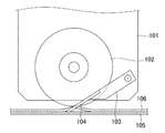
この種の裁断装置として、カッターヘッドにカッターとしての回転刃と固定刃を設け、回転刃と固定刃のせん断作用により布地を裁断するものがある(例えば、特許文献1参照)。この裁断装置は、図7に示すように、カッターヘッドのフレーム101に回転自在に枢着された回転刃102と、上記フレーム101に基端が連結された板バネ103と、この板バネ103の先端に固定されて回転刃102の刃先に付勢されて接触する固定刃104を備える。この裁断装置は、裁断テーブルのコンベヤベルト105上に支持された布地106を固定刃104が支持面側からすくい上げた状態で、固定刃104の先端側である矢印Fの方向にカッターヘッドが駆動される。回転刃102と固定刃104のせん断作用で布地106を切断すると共に、カッターヘッドを裁断パターンに応じた経路に駆動することにより、裁断パターンの形状に布地106を裁断するように構成されている。
As this type of cutting device, there is a device in which a cutter blade is provided with a rotary blade and a fixed blade as a cutter, and the fabric is cut by the shearing action of the rotary blade and the fixed blade (for example, see Patent Document 1). As shown in FIG. 7, the cutting device includes a
しかしながら、特許文献1の裁断装置は、回転刃102や固定刃104の切れ味の低下や布地の皺等に起因して、固定刃104が布地106から過大な抵抗力を受け、布地106に引っ掛かる場合がある。固定刃104が布地106に引っ掛かると、カッターヘッドの駆動方向に布地106を移動させて裁断動作が中断する不都合や、布地106が破損する不都合を招く恐れがある。また、固定刃104が布地106に引っ掛かったままカッターヘッドの駆動力が作用することにより、固定刃104が破損する恐れがある。
However, the cutting device disclosed in
そこで、本発明の課題は、固定刃がシート材から抵抗力を受けても、シート材の移動や破損を防止でき、また、固定刃の破損を防止できる裁断装置を提供することにある。 Therefore, an object of the present invention is to provide a cutting device that can prevent the movement and breakage of the sheet material and prevent the breakage of the fixed blade even when the fixed blade receives a resistance force from the sheet material.
上記課題を解決するため、本発明の裁断装置は、シート材を支持する支持面を有する支持部と、
上記支持部の支持面に支持されたシート材を、このシート材に上記支持面に遠い側から接する第1の刃と、上記シート材に支持面に近い側から接する第2の刃とで切断するカッターヘッドと、
上記カッターヘッドを支持面と平行の面内に駆動するヘッド駆動部と、
上記第2の刃にシート材から所定の抵抗力が作用するに伴い、この第2の刃をカッターヘッドの駆動方向と反対方向に退避させる退避機構と
を備えることを特徴としている。
In order to solve the above problems, the cutting apparatus of the present invention includes a support portion having a support surface for supporting a sheet material,
The sheet material supported by the support surface of the support portion is cut with a first blade that comes into contact with the sheet material from a side far from the support surface and a second blade that comes into contact with the sheet material from a side near the support surface. A cutter head to
A head drive unit for driving the cutter head in a plane parallel to the support surface;
A retraction mechanism is provided that retreats the second blade in a direction opposite to the driving direction of the cutter head when a predetermined resistance force acts on the second blade from the sheet material.
上記構成によれば、支持部の支持面に支持されたシート材が、カッターヘッドの第1及び第2の刃で切断されると共に、このカッターヘッドがヘッド駆動部で支持面と平行の面内に駆動される。第1及び第2の刃がシート材を切断する際、第2の刃にシート材から所定の抵抗力が作用すると、退避機構によって第2の刃がカッターヘッドの駆動方向と反対方向に退避させられる。したがって、第2の刃は、支持面に近い側からシート材に接するにもかかわらず、シート材に引っ掛かることが防止される。その結果、第2の刃がシート材に引っ掛かった状態でカッターヘッドがヘッド駆動部で駆動されてシート材が移動する不都合や、シート材が第1又は第2の刃で破損する不都合が防止される。また、第2の刃がシート材に引っ掛かった状態でカッターヘッドの駆動力が作用することにより、第2の刃が破損する不都合が防止される。 According to the above configuration, the sheet material supported by the support surface of the support unit is cut by the first and second blades of the cutter head, and the cutter head is in a plane parallel to the support surface by the head drive unit. Driven by. When the first and second blades cut the sheet material, if a predetermined resistance force acts on the second blade from the sheet material, the second blade is retracted in the direction opposite to the driving direction of the cutter head by the retracting mechanism. It is done. Therefore, the second blade is prevented from being caught by the sheet material despite being in contact with the sheet material from the side close to the support surface. As a result, the inconvenience that the cutter head is driven by the head drive unit while the second blade is caught by the sheet material and the sheet material moves, and the inconvenience that the sheet material is damaged by the first or second blade are prevented. The Further, the driving force of the cutter head acts in a state where the second blade is caught by the sheet material, thereby preventing the second blade from being damaged.
一実施形態の裁断装置は、上記カッターヘッドの第1の刃は、回転刃であり、
上記カッターヘッドの第2の刃は、先端が上記カッターヘッドの駆動方向を向いて上記回転刃に接する固定刃であり、
上記退避機構は、上記カッターヘッドの固定刃を、上記シート材から受けた抵抗力により、先端が上記カッターヘッドの駆動方向と反対方向を向くように反転させる反転機構である。
In the cutting device of one embodiment, the first blade of the cutter head is a rotary blade,
The second blade of the cutter head is a fixed blade whose tip is in contact with the rotary blade with the drive direction of the cutter head facing
The retraction mechanism is a reversing mechanism that reverses the fixed blade of the cutter head so that the tip is directed in a direction opposite to the driving direction of the cutter head by a resistance force received from the sheet material.
上記実施形態によれば、シート材がカッターヘッドの回転刃と固定刃で切断され、上記固定刃にシート材から抵抗力が作用するに伴い、この抵抗力により、上記固定刃がカッターヘッドの駆動方向と反対方向に先端を向くように反転されられる。これにより、固定刃がシート材に引っ掛かることを効果的に防止でき、したがって、固定刃がシート材に引っ掛かってシート材が移動する不都合や、シート材が破損する不都合や、固定刃が破損する不都合を防止できる。 According to the above embodiment, as the sheet material is cut by the rotary blade and the fixed blade of the cutter head, and the resistance force acts on the fixed blade from the sheet material, the resistance blade causes the fixed blade to drive the cutter head. Inverted so that the tip faces in the opposite direction. As a result, the fixed blade can be effectively prevented from being caught by the sheet material, and therefore, the inconvenience that the fixed blade is caught by the sheet material and the sheet material is moved, that the sheet material is damaged, and that the fixed blade is damaged. Can be prevented.
一実施形態の裁断装置は、上記反転機構を介して上記固定刃を支持すると共に、この固定刃を回転刃の刃先に付勢する付勢支持部を備え、
上記反転機構は、上記付勢支持部に揺動可能に枢着されて上記固定刃を保持する固定刃ホルダと、この固定刃ホルダを吸着して上記固定刃を上記回転刃に接触する位置に保持する吸着部を有する。
The cutting apparatus according to an embodiment includes a biasing support portion that supports the fixed blade via the reversing mechanism and biases the fixed blade against the blade edge of the rotary blade,
The reversing mechanism includes a fixed blade holder that is pivotally attached to the urging support portion and holds the fixed blade, and a position that adsorbs the fixed blade holder to bring the fixed blade into contact with the rotary blade. It has a suction part to hold.
上記実施形態によれば、付勢支持部で固定刃が回転刃の刃先に付勢されることにより、固定刃と回転刃によりシート材が効果的に切断される。上記固定刃は、上記付勢支持部に枢着された固定刃ホルダに保持され、この固定刃ホルダが吸着部で吸着されて、上記回転刃に接触する位置に保持される。シート材を切断する際に所定の抵抗力が作用すると、吸着部による固定刃ホルダの保持が解除され、固定ホルダが揺動して固定刃がカッターヘッドの駆動方向と反対方向に先端を向くように反転する。こうして、固定刃を安定して保持してシート材を裁断できると共に、所定の抵抗力を受けたときには固定刃を速やかに退避させることができる。 According to the embodiment, the sheet material is effectively cut by the fixed blade and the rotary blade when the fixed blade is urged to the cutting edge of the rotary blade by the urging support portion. The fixed blade is held by a fixed blade holder pivotally attached to the urging support portion, and the fixed blade holder is sucked by the suction portion and held at a position where it comes into contact with the rotary blade. If a predetermined resistance is applied when cutting the sheet material, the holding of the fixed blade holder by the suction portion is released, and the fixed holder swings so that the fixed blade faces the tip in the direction opposite to the driving direction of the cutter head. Invert to. Thus, the fixed blade can be stably held and the sheet material can be cut, and the fixed blade can be quickly retracted when a predetermined resistance is applied.
一実施形態の裁断装置は、上記付勢支持部は、上記反転機構及び固定刃を支持面に対して接離可能に形成され、
上記付勢支持部に付勢力を与えて上記固定刃を支持面側に保持する支持面側付勢手段を備える。
In the cutting device according to an embodiment, the urging support portion is formed so that the reversing mechanism and the fixed blade can be brought into contact with and separated from the support surface.
Support surface side urging means is provided that applies an urging force to the urging support portion to hold the fixed blade on the support surface side.
上記実施形態によれば、付勢支持部が、反転機構及び固定刃を支持面に対して接離可能に形成され、この付勢支持部に支持面側付勢手段によって付勢力が与えられることにより、支持面側に固定刃が安定して保持されてシート材が安定して裁断される。ここで、シート材から固定刃に所定の抵抗力が作用すると、反転機構によって固定刃がカッターヘッドの駆動方向と反対方向に先端がむくように反転するが、このとき、反転機構及び固定刃が支持面に対して離隔するので固定刃を確実に反転させることができる。また、付勢支持部が支持面側付勢手段から付勢力を受けているので、反転した固定刃を速やかに支持面側に押圧して固定刃を安定させることができる。 According to the embodiment, the urging support portion is formed so that the reversing mechanism and the fixed blade can be brought into contact with and separated from the support surface, and the urging force is given to the urging support portion by the support surface side urging means. Thus, the fixed blade is stably held on the support surface side, and the sheet material is stably cut. Here, when a predetermined resistance force acts on the fixed blade from the sheet material, the fixed blade is reversed by the reversing mechanism so that the tip is peeled in the direction opposite to the driving direction of the cutter head. At this time, the reversing mechanism and the fixed blade are Since it is separated from the support surface, the fixed blade can be reliably reversed. Further, since the urging support part receives the urging force from the support surface side urging means, the fixed blade that has been reversed can be quickly pressed against the support surface side to stabilize the fixed blade.
一実施形態の裁断装置は、上記付勢支持部は、一端に上記反転機構及び固定刃が配置されている一方、他端に、この付勢支持部を揺動可能に支持する揺動軸が設けられていると共に揺動レバーが連結されており、この揺動レバーに上記支持面側付勢手段によって付勢力が作用され、
上記回転刃でシート材に切り込みを形成する際に、上記揺動レバーを上記支持面側付勢手段の付勢力に抗して上記固定刃を支持面から離隔する方向に駆動力を作用させる一方、上記固定刃及び回転刃でシート材を裁断する際に、上記揺動レバーへの駆動力を解除する駆動手段を備える。
In the cutting device according to an embodiment, the biasing support portion includes the reversing mechanism and the fixed blade disposed at one end, and a swing shaft that rotatably supports the biasing support portion at the other end. And a swing lever is connected to the swing lever, and a biasing force is applied to the swing lever by the support surface side biasing means.
When the slit is formed in the sheet material by the rotary blade, the swing lever is applied with a driving force in a direction separating the fixed blade from the support surface against the biasing force of the support surface side biasing means. Drive means for releasing the driving force to the swing lever when the sheet material is cut with the fixed blade and the rotary blade is provided.
上記実施形態によれば、付勢支持部の一端に反転機構及び固定刃が配置されている一方、この付勢支持部の他端に、揺動軸が設けられていると共に揺動レバーが連結されている。この連結レバーに、支持面側付勢手段によって付勢力が作用される。これらにより、反転機構及び固定刃が簡易な構成で支持面に対して接離可能となると共に、固定刃が支持面側に付勢される。その結果、固定刃が確実に反転可能な状態で、固定刃と回転刃で安定してシートを切断できる。ここで、例えばシート材の裁断を開始する場合、駆動手段により、上記揺動レバーに駆動力が作用して固定刃が支持面から離隔し、これにより、回転刃でシート材に効果的に切り込みを形成することができる。一方、駆動手段による揺動レバーの駆動力が解除されると、支持面付勢手段から揺動部に作用する付勢力によって固定刃が支持面側に保持され、固定刃及び回転刃の切断機能を安定して発揮させることができる。ここで、上記駆動手段としては、例えばエアシリンダ、リニア電磁ソレノイド、リニアモータ、リニア振動アクチュエータ、リニア電磁ポンプ等の線形駆動装置を用いることができ、上記駆動手段の動作形式は、電気式、油圧式、空気圧式の種々のものを用いることができる。 According to the above embodiment, the reversing mechanism and the fixed blade are arranged at one end of the urging support portion, while the oscillating shaft is provided at the other end of the urging support portion and the oscillating lever is connected. Has been. A biasing force is applied to the connecting lever by the support surface side biasing means. Accordingly, the reversing mechanism and the fixed blade can be brought into contact with and separated from the support surface with a simple configuration, and the fixed blade is biased toward the support surface. As a result, the sheet can be stably cut with the fixed blade and the rotary blade while the fixed blade can be reliably reversed. Here, for example, when cutting of the sheet material is started, a driving force is applied to the rocking lever by the driving means so that the fixed blade is separated from the support surface, thereby effectively cutting the sheet material with the rotary blade. Can be formed. On the other hand, when the drive force of the swing lever by the drive means is released, the fixed blade is held on the support surface side by the biasing force that acts on the swing portion from the support surface biasing means, and the cutting function of the fixed blade and the rotary blade Can be exhibited stably. Here, as the drive means, for example, a linear drive device such as an air cylinder, a linear electromagnetic solenoid, a linear motor, a linear vibration actuator, a linear electromagnetic pump, etc. can be used. Various types of pneumatic and pneumatic types can be used.
一実施形態の裁断装置は、上記反転機構による固定刃の反転を検知するセンサと、
上記センサから上記固定刃の反転を示す信号を受けると、上記ヘッド駆動部の動作を停止させる制御部とを備える。
The cutting device of one embodiment includes a sensor that detects the reversal of the fixed blade by the reversing mechanism,
A control unit that stops the operation of the head driving unit when receiving a signal indicating the reversal of the fixed blade from the sensor;
上記実施形態によれば、反転機構による固定刃の反転がセンサで検知され、このセンサから検知信号を制御部が受けると、この制御部の制御により、ヘッド駆動部の動作が停止する。したがって、固定刃が反転してシート材の裁断が停止する位置に、カッターヘッドを停止させることができるので、カッターヘッドの構成部品によりシート材が移動又は破損する不都合や、カッターヘッドの構成部品がシート材からの抵抗力で破損する不都合を防止できる。ここで、上記センサとしては、検知媒体として磁界、電磁波、電界、光及び超音波を用いた近接センサ、変位センサ及び測距センサ等の種々のセンサを用いることができる。また、上記センサとして、接触式のスイッチを用いてもよい。 According to the above embodiment, when the reversal of the fixed blade by the reversing mechanism is detected by the sensor and the control unit receives a detection signal from the sensor, the operation of the head driving unit is stopped by the control of the control unit. Therefore, the cutter head can be stopped at the position where the fixed blade is reversed and the cutting of the sheet material is stopped. The inconvenience of being damaged by the resistance force from the sheet material can be prevented. Here, as the sensor, various sensors such as a proximity sensor using a magnetic field, an electromagnetic wave, an electric field, light, and an ultrasonic wave as a detection medium, a displacement sensor, and a distance measuring sensor can be used. Further, a contact type switch may be used as the sensor.
一実施形態の裁断装置は、上記付勢支持部の支持面からの離隔動作を検知するセンサと、
上記センサから、上記付勢支持部の支持面からの離隔動作を示す信号を受けると、上記ヘッド駆動部の動作を停止させる制御部とを備える。
The cutting device of an embodiment includes a sensor that detects a separation operation from the support surface of the biasing support portion,
And a control unit that stops the operation of the head drive unit when receiving a signal indicating a separation operation from the support surface of the biasing support unit from the sensor.
上記実施形態によれば、付勢支持部の支持面からの離隔動作がセンサで検知されることにより、固定刃がカッターヘッドの駆動方向と反対方向に反転したことが検知され、したがって、シート材の裁断が停止したことが検知される。上記センサから検知信号を制御部が受けると、この制御部の制御により、ヘッド駆動部の動作が停止する。したがって、シート材の裁断が停止した位置に、カッターヘッドを停止させることができるので、カッターヘッドの構成部品によりシート材が移動又は破損する不都合や、カッターヘッドの構成部品がシート材からの抵抗力で破損する不都合を防止できる。ここで、上記センサとしては、検知媒体として磁界、電磁波、電界、光及び超音波を用いた近接センサ、変位センサ及び測距センサ等の種々のセンサを用いることができる。また、上記センサとして、接触式のスイッチを用いてもよい。 According to the above embodiment, the separation operation from the support surface of the urging support portion is detected by the sensor, whereby it is detected that the fixed blade is reversed in the direction opposite to the driving direction of the cutter head. It is detected that the cutting process has stopped. When the control unit receives a detection signal from the sensor, the operation of the head driving unit is stopped by the control of the control unit. Therefore, since the cutter head can be stopped at the position where the cutting of the sheet material is stopped, the inconvenience that the sheet material is moved or damaged by the components of the cutter head and the components of the cutter head are resistant to the sheet material. Can prevent inconvenience of being damaged. Here, as the sensor, various sensors such as a proximity sensor using a magnetic field, an electromagnetic wave, an electric field, light, and an ultrasonic wave as a detection medium, a displacement sensor, and a distance measuring sensor can be used. Further, a contact type switch may be used as the sensor.
一実施形態の裁断装置は、上記センサからの検知信号を受けて、上記回転刃の動作を停止する回転刃制御部を備える。 The cutting apparatus of one Embodiment is provided with the rotary blade control part which receives the detection signal from the said sensor and stops the operation | movement of the said rotary blade.
上記実施形態によれば、センサからの検知信号を受けて、固定刃の反転や付勢支持部の支持面からの離隔動作が検知されると、回転刃制御部の制御により、カッターヘッドの回転刃の動作が停止する。したがって、カッターヘッドの駆動が停止した際に、回転刃でシート材が不正に切断される不都合を防止できる。 According to the embodiment described above, when the reversal of the fixed blade or the separation operation from the support surface of the urging support portion is detected in response to the detection signal from the sensor, the rotation of the cutter head is controlled by the control of the rotary blade control portion. The blade stops moving. Therefore, when the driving of the cutter head is stopped, it is possible to prevent inconvenience that the sheet material is illegally cut by the rotary blade.
以下、本発明の実施形態を、添付の図面を参照しながら詳細に説明する。 Hereinafter, embodiments of the present invention will be described in detail with reference to the accompanying drawings.
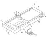
本発明の実施形態の裁断装置は、シート材としての布地を裁断して被服のパターンピースを作製するプロッタ型の裁断装置である。この裁断装置1は、図1に示すように、裁断テーブル2と、カッターユニット4と、解反機8と、制御部及び回転刃制御部としての制御装置11とで大略構成されている。
The cutting device according to an embodiment of the present invention is a plotter-type cutting device that cuts a fabric as a sheet material to produce a pattern piece of clothing. As shown in FIG. 1, the
裁断テーブル2は、布地10を解反機8から搬送すると共に裁断時に布地10を支持するベルトコンベヤを内蔵している。ベルトコンベヤは、裁断テーブル2の長手方向の両端に内蔵されて短手方向に延在する図示しないプーリの間に、支持部としてのコンベヤベルト3が掛け渡されて構成されている。このベルトコンベヤを構成するコンベヤベルト3の上側部の表面が、裁断テーブル2の上側面に露出して、支持面3aとして機能する。コンベヤベルト3は、基布46に立毛47が編み込まれてなるモケット状のシートで形成されている。
The cutting table 2 incorporates a belt conveyor that conveys the
カッターユニット4は、裁断テーブル2の長手方向の縁部に設置された2つのレールに沿って走行する一対のキャリッジ5と、これら1対のキャリッジ5,5の間に掛け渡されて裁断テーブル2の短手方向に延在する梁部材6と、この梁部材6に設置されたレールに沿って走行するカッターヘッド7を備える。カッターヘッド7は、後述のように、布地10を切断する回転刃28と固定刃43を内蔵している。カッターヘッド7は、キャリッジ5により裁断テーブル2の長手方向に移動すると共に、カッターヘッド7に内蔵された駆動機構により裁断テーブル2の短手方向に移動することにより、裁断テーブル2の支持面3aと平行の面内に駆動される。このように、キャリッジ5とカッターヘッド7の駆動機構により、ヘッド駆動部が構成されている。
The cutter unit 4 is spanned between a pair of
解反機8は、ベルトコンベヤの一端側に、裁断テーブル2の短辺に隣接して配置されている。解反機8は、布地のロール9が載置された状態で、このロール9を回転駆動して布地10を巻き出すものである。この解反機8は、図示しないモータによって回転駆動され、回転軸が所定間隔をおいて平行に配置された2つの解反ローラを有する。これら2つの解反ローラに接するように、解反ローラの間の上側にロール9が載置され、解反ローラが回転するに伴ってロール9から布地を巻き出すように構成されている。解反機8には、解反ローラよりも裁断テーブル2側に、解反ローラから巻き出された布地10を裁断テーブル2に送るガイドローラが設けられている。
The unraveling
制御装置11は、裁断テーブル2及び解反機8に接続され、裁断テーブル2の支持面3aに布地10を引き出す際の解反機8及びベルトコンベヤの動作と、支持面3a上に載置された布地10を裁断する際のカッターユニット4の動作を制御する。制御装置11は、市販のノート型PC(パーソナルコンピュータ)によって構成されている。制御装置11は、解反機8の巻き出し動作や、ベルトコンベヤの動作や、カッターユニット4の動作や、裁断パターン50の情報に関する入力を操作者から受け、受け付けた入力に基づいて、解反機8、ベルトコンベヤ及びカッターユニット4の動作を制御する。なお、制御装置11と同様の機能を有する制御部又は回転刃制御部を裁断テーブル2や解反機8に内蔵し、裁断テーブル2のカッターユニット4のキャリッジ5や、解反機8のフレーム等に、タッチパネル等で形成された指令入力部を設けてもよい。
The
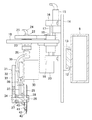
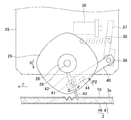
図2は、カッターヘッド7の構成を示す部分断面図である。カッターヘッド7は、板状のフレーム14の背面に設けられたガイド13により、梁部材6の側面に固定されたガイドレール12に沿って移動可能に構成されている。カッターヘッド7は、内部に設置された図示しないモータにより、或いは、キャリッジ5,5の間に掛け渡されてフレームに固定された駆動ワイヤにより、ガイドレール12の延在方向に駆動される。
FIG. 2 is a partial cross-sectional view showing the configuration of the
カッターヘッド7のフレーム14の正面には、上下に離間して設置された一対の取り付けアーム16,16の間に、ガイド軸17が取り付けられている。このガイド軸17には、上下動フレーム19に固定されたスライド軸受け18が嵌合しており、この上下動フレーム19は、ロッドの先端が連結された上下動シリンダー15によって、ガイド軸17に沿って上下方向に駆動される。上記上下動フレーム19には、カッター旋回用モータ20が設置されており、このカッター旋回用モータ20の回転力は、カッター旋回用プーリ21によって、旋回軸受け23で支持された中空状の旋回軸22に伝達される。旋回軸22の上端は、固定刃移動用のエアジョイント24に連結されている一方、旋回軸22の下端には、板状の刃物フレーム25が固定されている。
On the front surface of the
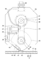
上記刃物フレーム25の下端よりもやや上方の位置に軸孔が形成されており、この軸孔に、刃物軸受27で刃物フレーム25に回転自在に支持された刃物軸26が挿通されている。刃物軸26の一端には、刃物止めナット28によって回転刃29が固定されている。回転刃29は、刃物フレーム25を正面側から視た図3に示すように、各辺が外径側に膨出して角部が丸みを帯びた四角形に形成されている。なお、回転刃29は、各辺が外径側に膨出して角部が丸みを帯びた多角形でもよく、或いは、円形でもよい。刃物フレーム25の旋回軸22の固定位置の下方には、刃物回転用モータ30が固定されており、この刃物回転モータ30の出力軸31に駆動プーリ32が固定されている。駆動プーリ32の下方に位置する刃物軸26の他端に、従動プーリ34が固定されており、上記駆動プーリ32と従動プーリ34に歯付ベルト33が巻き回されている。刃物回転モータ30の回転力が、駆動プーリ32から歯付ベルト33を通して従動プーリ34に伝達され、刃物軸26が回転し、回転刃29が回転駆動されるように構成されている。
A shaft hole is formed at a position slightly above the lower end of the
上記刃物フレーム25の下端よりもやや上方の位置には、刃物軸26に関してカッターの進行方向と反対側に、互いに連結された揺動レバー37及び付勢支持部としての板バネ40を揺動可能に枢着する揺動軸38が設けられている。
At a position slightly above the lower end of the
揺動レバー37は、刃物フレーム25の回転刃29が配置された側と反対側に配置されており、揺動軸38の一端に揺動レバー37の下端が固定されている。上記刃物フレーム25の駆動プーリ32と従動プーリ34の間、かつ、カッターの進行方向と反対側には、揺動レバー37を駆動する固定刃シリンダー36が固定されており、この固定刃シリンダー36には、旋回軸22の下端に一端が接続されたエアホース35の他端が接続されている。この固定刃シリンダー36のロッドの先端が、上記揺動レバー37の上端よりもやや下方の位置に当接して揺動レバー37を揺動駆動する。この揺動レバー37の上記固定刃シリンダー36のロッドの当接位置よりも揺動軸38側に、支持面側付勢手段としてのコイルバネ39が連結されている。このコイルバネ39で揺動レバー37を固定刃シリンダー36側に付勢し、この揺動レバー37に連結された板バネ40の先端の固定刃43を、支持面側に付勢している。
The
板バネ40は、刃物フレーム25の回転刃29が配置された側に配置されている。板バネ40の基端は、上記揺動軸38の他端に固定されており、図3に示される刃物フレーム25の正面視において、揺動レバー37との間に約120°の角度をなしている。
The
板バネ40の先端には、固定刃43を保持する固定刃ホルダ42が反転軸41によって枢着されている。固定刃ホルダ42は、直方体の揺動軸38側に凸部を有する形状であり、この凸部の側面が、吸着部としての永久磁石44に吸着される被吸着部となっている。永久磁石44は、固定刃ホルダ42の凸部を吸着して、上記固定刃ホルダ42に保持された固定刃43を適正な姿勢に保持するように構成されている。板バネ40は、固定刃43を、刃物フレーム25の正面視において、回転刃28の刃物軸26が通る鉛直線上で回転刃28の刃先に付勢している。吸着部としての永久磁石44の吸着力は、固定刃43と回転刃29による切断動作を阻害しない程度の強さに設定されている。
A fixed
上記刃物フレーム25には、上記揺動レバー37の揺動を検知する図示しないリミットスイッチが設けられている。カッターヘッド7が駆動されて布地10の裁断を行っている際に、板バネ40の固定刃43が支持面3aから離隔する方向に揺動し、これにより揺動レバー37の先端部が固定刃シリンダー36から遠ざかる方向に揺動レバー37が揺動すると、リミットスイッチから検知信号が出力される。リミットスイッチからの検知信号は制御装置11に入力され、これに応じて、制御装置11が刃物回転用モータ30の回転を停止する制御を行うと共に、キャリッジ5とカッターヘッド7の駆動機構によるカッターヘッド7の駆動を停止する。なお、上記リミットスイッチは、光学式、電磁式及び接触式のいずれの形式でもよい。また、リミットスイッチからの検知信号に応じた刃物回転用モータ30及びカッターヘッド7の制御は、裁断テーブル2内に設けた制御部で行ってもよい。
The
上記構成の裁断装置により、布地10を裁断してパターンピースを作製する動作を説明する。
An operation of cutting the
まず、操作者により、解反機8の解反ローラの上に布地のロール9が載置され、制御装置11に解反の指令が入力される。これに応じて解反ローラが動作し、ロール9から布地10が巻き出される。巻き出された布地10の先端部が、ベルトコンベヤの解反機8側の一端側の上側面に載置され、制御装置11に延出の指令が入力されると、解反機8の解反ローラが巻き出し動作を行うと共に、ベルトコンベヤが布地10を他端側に送る送り動作を行う。これにより、裁断テーブル2の支持面3a上の裁断領域に布地10が延出される。なお、裁断領域とは、カッターヘッド7のカッターにより裁断が実行可能な領域である。
First, the
裁断テーブル2の支持面3a上に布地1が延出されると、操作者により、裁断パターン50の形状を示す裁断データが制御装置11に入力される。制御装置11のディスプレイに、裁断データに対応する裁断パターン50の形状や位置が表示され、表示された情報を視認した操作者により、布地10上の裁断パターン50の位置及び角度が調節される。裁断パターン50の位置及び角度の調節が終了すると、操作者により裁断開始の指令が制御装置11に入力され、この入力に応じて制御装置11が裁断の制御を開始する。以下、制御装置11による制御の内容を説明する。
When the
まず、制御装置11は、キャリッジ5とカッターヘッド7の駆動機構を作動させ、カッターヘッド7を支持面3aと平行の面内で駆動して、カッターヘッド7の回転刃28を布地10の裁断を開始する裁断開始位置に配置する。カッターヘッド7を裁断開始位置まで移動させる間は、上下動シリンダー15で上下動フレーム19を最上位置に保持して、回転刃28及び固定刃43が布地10に引っ掛からないようにする。カッターヘッド7が裁断開始位置に到達すると、図4の矢印C1で示すように固定刃シリンダー36のロッドを突出させ、揺動レバー37を固定刃シリンダー36から遠ざけ、固定刃43を支持面3aから離隔するように板バネ40を揺動する。続いて、刃物回転モータ30を起動して回転刃29を矢印Rで示すように回転駆動すると共に、上下動シリンダー15を作動させ、上下動フレーム19を支持面3aの方向に、すなわち、下方に駆動する。これにより、回転する回転刃29の刃先が布地10に接触し、布地10の裁断開始位置に切り込みが形成される。ここで、布地10はモケット状のコンベヤベルト3に支持されているので、コンベヤベルト3の立毛47の先端に接触する布地10に、回転刃29が貫通して効果的に切り込みが形成され、しかも、コンベヤベルト3の基布46には回転刃29が達しないのでコンベヤベルト3の破損が防止される。
First, the
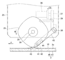
布地10の裁断開始位置に切り込みが形成されると回転刃29を一旦停止し、図5に示すように、固定刃シリンダー36のロッドを没入させる。これにより、収縮するコイルバネ39の付勢力によって揺動レバー37が固定刃シリンダー39側に揺動し、板バネ40が揺動して固定刃43が支持面3aに接近する。固定刃43が支持面3aに接近すると、板バネ40の付勢力により、固定刃43が回転刃29の刃先の側面を押圧する状態で接触する。これと共に、上下動シリンダー15を作動させ、上下動フレーム19を支持面3aから離隔する方向に、すなわち、上方に駆動する。これにより、固定刃43が布地10を支持面3aからすくい上げ、布地10の支持面3aと近い側に固定刃43が接する一方、布地10の支持面3aと遠い側に回転刃29が接する。続いて、矢印Rで示すように回転刃29の回転駆動を再開し、カッターヘッド7を矢印Fで示すように固定刃43の先端の向く方向に駆動する。なお、上記固定刃43を支持面3aに接近させて回転刃29の刃先に接触させると共に、上下動フレーム19を上方に駆動して固定刃43で布地10を支持面3aからすくい上げる一連の動作は、回転刃29の回転を継続した状態で行ってもよい。上記カッターヘッド7を、裁断パターンの形状に応じた経路に沿って平面方向に駆動すると共に、駆動方向に応じて旋回軸22回りに刃物フレーム25を旋回駆動することにより、固定刃43と回転刃29で裁断パターンに沿って布地10を切断し、パターンピースを作製する。
When the cut is formed at the cutting start position of the
こうしてカッターヘッド7が布地10の裁断動作を行う際、回転刃29や固定刃43の切れ味の低下や、布地10に生じた皺に起因して、過大な抵抗力が布地10から固定刃43に作用する場合がある。布地10からの過大な抵抗力は、多くの場合、回転刃29と固定刃43による切断線が途切れ、切断線の端に固定刃43が係止して生じる。固定刃43に過大な抵抗力が作用すると、図6に示すように、固定刃ホルダ42の被吸着部が永久磁石44の吸着力から開放され、固定刃43が矢印Sで示すように回動する。これにより、固定刃43の先端が、矢印Fで示されるカッターヘッド7の駆動方向と反対方向を向くように、固定刃43が反転する。このとき、固定刃43の先端が支持面3aから反力を受け、矢印P2で示すように板バネ40が上方に揺動するので、固定刃43の先端が支持面3aに引っ掛かることなく固定刃43が円滑に反転する。板バネ40が揺動して揺動レバー37が揺動すると、リミットスイッチが揺動レバー37の揺動を検知して検知信号を出力し、これに応じて刃物回転用モータ30が停止すると共に、キャリッジ5とカッターヘッド7の駆動機構が停止する。
Thus, when the
このように、過大な抵抗力が布地10から固定刃43に作用すると、固定刃43が反転してカッターヘッド7の駆動経路から退避すると共に、回転刃29の回転とカッターヘッド7の駆動が停止する。その結果、固定刃43が布地10に引っ掛かって布地10をカッターヘッド7の駆動方向に移動させる不都合を防止することができる。また、布地10から固定刃43に過大な抵抗力が持続して作用することを防止できるので、布地10の破損や固定刃43の破損を防止できる。さらに、回転刃29の回転を停止するので、固定刃43の反転に伴って布地10が浮き上がり、浮き上がった布地10が回転刃29に接触しても、布地10が不正に切断される不都合を防止できる。
Thus, when an excessive resistance force acts on the fixed
上記実施形態では、センサとしてのリミットスイッチが、揺動レバー37の揺動を検知したが、板バネ40の揺動を検知してもよい。また、センサは、固定刃43の反転を検知してもよい。
In the above embodiment, the limit switch as a sensor detects the swing of the
また、上記実施形態の裁断装置1は、シート材としての布地を裁断したが、皮革や紙や樹脂等の他のシート材を裁断してもよい。
Moreover, although the
また、本発明は、プロッタ型の裁断装置に限らず、カッターヘッドが所定位置に固定された裁断装置や、カッターヘッドが一方向のみに駆動される裁断装置にも適用できる。 The present invention is not limited to a plotter-type cutting device, and can also be applied to a cutting device in which a cutter head is fixed at a predetermined position, or a cutting device in which the cutter head is driven only in one direction.
1 裁断装置
2 裁断テーブル
3 コンベヤベルト
3a 支持面
4 カッターユニット
7 カッターヘッド
28 回転刃
40 板バネ
41 反転軸
42 固定刃ホルダ
43 固定刃
DESCRIPTION OF
Claims (8)
上記支持部の支持面に支持されたシート材を、このシート材に上記支持面に遠い側から接する第1の刃と、上記シート材に支持面に近い側から接する第2の刃とで切断するカッターヘッドと、
上記カッターヘッドを支持面と平行の面内に駆動するヘッド駆動部と、
上記第2の刃にシート材から所定の抵抗力が作用するに伴い、この第2の刃をカッターヘッドの駆動方向と反対方向に退避させる退避機構と
を備えることを特徴とする裁断装置。 A support portion having a support surface for supporting the sheet material;
The sheet material supported by the support surface of the support portion is cut with a first blade that comes into contact with the sheet material from a side far from the support surface and a second blade that comes into contact with the sheet material from a side near the support surface. A cutter head to
A head drive unit for driving the cutter head in a plane parallel to the support surface;
A cutting device comprising: a retracting mechanism for retracting the second blade in a direction opposite to the driving direction of the cutter head when a predetermined resistance force acts on the second blade from the sheet material.
上記カッターヘッドの第1の刃は、回転刃であり、
上記カッターヘッドの第2の刃は、先端が上記カッターヘッドの駆動方向を向いて上記回転刃に接する固定刃であり、
上記退避機構は、上記カッターヘッドの固定刃を、上記シート材から受けた抵抗力により、先端が上記カッターヘッドの駆動方向と反対方向を向くように反転させる反転機構であることを特徴とする裁断装置。 The cutting apparatus according to claim 1,
The first blade of the cutter head is a rotary blade,
The second blade of the cutter head is a fixed blade whose tip is in contact with the rotary blade with the drive direction of the cutter head facing
The retraction mechanism is a reversing mechanism for reversing the fixed blade of the cutter head so that the tip is directed in a direction opposite to the driving direction of the cutter head by a resistance force received from the sheet material. apparatus.
上記反転機構を介して上記固定刃を支持すると共に、この固定刃を回転刃の刃先に付勢する付勢支持部を備え、
上記反転機構は、上記付勢支持部に揺動可能に枢着されて上記固定刃を保持する固定刃ホルダと、この固定刃ホルダを吸着して上記固定刃を上記回転刃に接触する位置に保持する吸着部を有することを特徴とする裁断装置。 The cutting device according to claim 2,
While supporting the fixed blade through the reversing mechanism, and including a biasing support portion for biasing the fixed blade against the cutting edge of the rotary blade,
The reversing mechanism includes a fixed blade holder that is pivotally attached to the urging support portion and holds the fixed blade, and a position that adsorbs the fixed blade holder to bring the fixed blade into contact with the rotary blade. A cutting apparatus having a holding portion for holding.
上記付勢支持部は、上記反転機構及び固定刃を支持面に対して接離可能に形成され、
上記付勢支持部に付勢力を与えて上記固定刃を支持面側に保持する支持面側付勢手段を備えることを特徴とする裁断装置。 The cutting device according to claim 2,
The urging support part is formed so that the reversing mechanism and the fixed blade can be brought into contact with and separated from the support surface.
A cutting apparatus comprising: a supporting surface side urging means that applies a urging force to the urging support portion to hold the fixed blade on a supporting surface side.
上記付勢支持部は、一端に上記反転機構及び固定刃が配置されている一方、他端に、この付勢支持部を揺動可能に支持する揺動軸が設けられていると共に揺動レバーが連結されており、この揺動レバーに上記支持面側付勢手段によって付勢力が作用され、
上記回転刃でシート材に切り込みを形成する際に、上記揺動レバーを上記支持面側付勢手段の付勢力に抗して上記固定刃を支持面から離隔する方向に駆動力を作用させる一方、上記固定刃及び回転刃でシート材を裁断する際に、上記揺動レバーへの駆動力を解除する駆動手段を備えることを特徴とする裁断装置。 In the cutting device according to claim 4,
The urging support portion is provided with the reversing mechanism and the fixed blade at one end, and at the other end is provided with a swinging shaft that swingably supports the biasing support portion and a swing lever. The urging force is applied to the swing lever by the support surface side urging means,
When the slit is formed in the sheet material by the rotary blade, the swing lever is applied with a driving force in a direction separating the fixed blade from the support surface against the biasing force of the support surface side biasing means. A cutting device comprising a driving means for releasing a driving force to the swing lever when the sheet material is cut with the fixed blade and the rotary blade.
上記反転機構による固定刃の反転を検知するセンサと、
上記センサから上記固定刃の反転を示す信号を受けると、上記ヘッド駆動部の動作を停止させる制御部と
を備えることを特徴とする裁断装置。 The cutting device according to claim 2,
A sensor for detecting the reversal of the fixed blade by the reversing mechanism;
A cutting device comprising: a control unit that stops the operation of the head driving unit when receiving a signal indicating the reversal of the fixed blade from the sensor.
上記付勢支持部の支持面からの離隔動作を検知するセンサと、
上記センサから、上記付勢支持部の支持面からの離隔動作を示す信号を受けると、上記ヘッド駆動部の動作を停止させる制御部と
を備えることを特徴とする裁断装置。 In the cutting device according to claim 4,
A sensor for detecting a separation operation from the support surface of the urging support portion;
A cutting device comprising: a control unit that stops the operation of the head driving unit when receiving a signal indicating a separation operation from the support surface of the biasing support unit from the sensor.
上記センサからの検知信号を受けて、上記回転刃の動作を停止する回転刃制御部を備えることを特徴とする裁断装置。 In the cutting device according to claim 6 or 7,
A cutting apparatus comprising: a rotary blade control unit that receives a detection signal from the sensor and stops the operation of the rotary blade.
Priority Applications (3)
| Application Number | Priority Date | Filing Date | Title |
|---|---|---|---|
| JP2011030061A JP5106646B2 (en) | 2011-02-15 | 2011-02-15 | Cutting device |
| PCT/JP2012/000691 WO2012111268A1 (en) | 2011-02-15 | 2012-02-01 | Cutting apparatus |
| CN201280009004.5A CN103391833B (en) | 2011-02-15 | 2012-02-01 | Cutting device |
Applications Claiming Priority (1)
| Application Number | Priority Date | Filing Date | Title |
|---|---|---|---|
| JP2011030061A JP5106646B2 (en) | 2011-02-15 | 2011-02-15 | Cutting device |
Publications (2)
| Publication Number | Publication Date |
|---|---|
| JP2012166316A true JP2012166316A (en) | 2012-09-06 |
| JP5106646B2 JP5106646B2 (en) | 2012-12-26 |
Family
ID=46672215
Family Applications (1)
| Application Number | Title | Priority Date | Filing Date |
|---|---|---|---|
| JP2011030061A Expired - Fee Related JP5106646B2 (en) | 2011-02-15 | 2011-02-15 | Cutting device |
Country Status (3)
| Country | Link |
|---|---|
| JP (1) | JP5106646B2 (en) |
| CN (1) | CN103391833B (en) |
| WO (1) | WO2012111268A1 (en) |
Cited By (1)
| Publication number | Priority date | Publication date | Assignee | Title |
|---|---|---|---|---|
| CN112176709A (en) * | 2020-11-04 | 2021-01-05 | 史者 | Rotary tailoring table for clothing design |
Families Citing this family (7)
| Publication number | Priority date | Publication date | Assignee | Title |
|---|---|---|---|---|
| CN106758114A (en) * | 2016-12-27 | 2017-05-31 | 铜陵龙嘉机电有限公司 | A kind of automatic cloth cutting device of textile machine and its cut cloth method |
| EP3603907B1 (en) * | 2017-03-23 | 2023-01-18 | Namx Company Limited | Cutting apparatus |
| CN108951092A (en) * | 2018-07-11 | 2018-12-07 | 安徽工美服装有限公司 | A kind of full-automatic cloth cutting machine of garment production |
| CN111893740B (en) * | 2020-08-31 | 2021-09-10 | 台州市黄岩伊蔓工贸有限公司 | Cutting and tensioning device during production of textile fabric |
| CN112192904A (en) * | 2020-10-29 | 2021-01-08 | 佳意新材料科技(重庆)有限公司 | Cutting device for production of flexible freight bags |
| JP7749485B2 (en) * | 2022-02-10 | 2025-10-06 | ローランドディー.ジー.株式会社 | Processing device with sheet cutter and media cutting method |
| CN116986088B (en) * | 2023-09-07 | 2025-11-25 | 福建佳隆胶带有限公司 | A tape cutting device in a carton sealing machine |
Citations (2)
| Publication number | Priority date | Publication date | Assignee | Title |
|---|---|---|---|---|
| JPH09285993A (en) * | 1996-04-23 | 1997-11-04 | Copyer Co Ltd | Recording material cutting device for image forming device |
| JPH10140468A (en) * | 1996-11-14 | 1998-05-26 | Namux:Kk | Fabric cutting machine and fabric cutting and stacking machine |
Family Cites Families (2)
| Publication number | Priority date | Publication date | Assignee | Title |
|---|---|---|---|---|
| US3803960A (en) * | 1972-12-11 | 1974-04-16 | Gerber Garment Technology Inc | System and method for cutting pattern pieces from sheet material |
| US5134911A (en) * | 1991-04-05 | 1992-08-04 | Gerber Garment Technology, Inc. | Method for the interrupted cutting of a line in sheet material |
-
2011
- 2011-02-15 JP JP2011030061A patent/JP5106646B2/en not_active Expired - Fee Related
-
2012
- 2012-02-01 CN CN201280009004.5A patent/CN103391833B/en not_active Expired - Fee Related
- 2012-02-01 WO PCT/JP2012/000691 patent/WO2012111268A1/en not_active Ceased
Patent Citations (2)
| Publication number | Priority date | Publication date | Assignee | Title |
|---|---|---|---|---|
| JPH09285993A (en) * | 1996-04-23 | 1997-11-04 | Copyer Co Ltd | Recording material cutting device for image forming device |
| JPH10140468A (en) * | 1996-11-14 | 1998-05-26 | Namux:Kk | Fabric cutting machine and fabric cutting and stacking machine |
Cited By (1)
| Publication number | Priority date | Publication date | Assignee | Title |
|---|---|---|---|---|
| CN112176709A (en) * | 2020-11-04 | 2021-01-05 | 史者 | Rotary tailoring table for clothing design |
Also Published As
| Publication number | Publication date |
|---|---|
| CN103391833B (en) | 2015-06-17 |
| WO2012111268A1 (en) | 2012-08-23 |
| CN103391833A (en) | 2013-11-13 |
| JP5106646B2 (en) | 2012-12-26 |
Similar Documents
| Publication | Publication Date | Title |
|---|---|---|
| JP5106646B2 (en) | Cutting device | |
| CN110461554B (en) | cutting device | |
| JP4136864B2 (en) | Web rewinding apparatus and method | |
| JP5406788B2 (en) | Cutting apparatus and cutting method | |
| JP6299393B2 (en) | Cutting device and printing device | |
| JP4424551B2 (en) | Label printer | |
| JP2014104688A (en) | Label printer | |
| JP6333143B2 (en) | Cutting device | |
| JP6111401B2 (en) | Sheet material processing machine | |
| JP4364830B2 (en) | Sheet material cutting equipment | |
| JP4590619B2 (en) | Automatic wallpaper pasting machine | |
| JP3231925U (en) | Sheet cutting device | |
| JP4866267B2 (en) | Labeling device | |
| JP5878079B2 (en) | Slitter for automatic wallpaper pasting machine and automatic wallpaper pasting machine equipped with the slitter | |
| JP3072557B2 (en) | Perforation cutter device | |
| JP4454379B2 (en) | Slitting machine for wallpaper gluing machine and wallpaper gluing machine with slitter | |
| JP3231924U (en) | Sheet cutting device | |
| JP5261759B2 (en) | Rolling hand towel manufacturing equipment | |
| JP3593942B2 (en) | Printing equipment | |
| JPH0314314Y2 (en) | ||
| JP2639614B2 (en) | Woodworking belt sander machine | |
| JP2008105140A (en) | Cutting plotter | |
| US20210008903A1 (en) | Cutter device and printing apparatus | |
| JP2015013722A (en) | Transportation device, image formation device, and transportation method | |
| JPH0321910Y2 (en) |
Legal Events
| Date | Code | Title | Description |
|---|---|---|---|
| TRDD | Decision of grant or rejection written | ||
| A01 | Written decision to grant a patent or to grant a registration (utility model) |
Free format text: JAPANESE INTERMEDIATE CODE: A01 Effective date: 20121002 |
|
| A01 | Written decision to grant a patent or to grant a registration (utility model) |
Free format text: JAPANESE INTERMEDIATE CODE: A01 |
|
| A61 | First payment of annual fees (during grant procedure) |
Free format text: JAPANESE INTERMEDIATE CODE: A61 Effective date: 20121002 |
|
| R150 | Certificate of patent or registration of utility model |
Ref document number: 5106646 Country of ref document: JP Free format text: JAPANESE INTERMEDIATE CODE: R150 Free format text: JAPANESE INTERMEDIATE CODE: R150 |
|
| FPAY | Renewal fee payment (event date is renewal date of database) |
Free format text: PAYMENT UNTIL: 20151012 Year of fee payment: 3 |
|
| S531 | Written request for registration of change of domicile |
Free format text: JAPANESE INTERMEDIATE CODE: R313531 |
|
| S533 | Written request for registration of change of name |
Free format text: JAPANESE INTERMEDIATE CODE: R313533 |
|
| R350 | Written notification of registration of transfer |
Free format text: JAPANESE INTERMEDIATE CODE: R350 |
|
| R250 | Receipt of annual fees |
Free format text: JAPANESE INTERMEDIATE CODE: R250 |
|
| R250 | Receipt of annual fees |
Free format text: JAPANESE INTERMEDIATE CODE: R250 |
|
| LAPS | Cancellation because of no payment of annual fees |