JP2012166310A - Machine tool bed - Google Patents
Machine tool bed Download PDFInfo
- Publication number
- JP2012166310A JP2012166310A JP2011029593A JP2011029593A JP2012166310A JP 2012166310 A JP2012166310 A JP 2012166310A JP 2011029593 A JP2011029593 A JP 2011029593A JP 2011029593 A JP2011029593 A JP 2011029593A JP 2012166310 A JP2012166310 A JP 2012166310A
- Authority
- JP
- Japan
- Prior art keywords
- rib
- bed
- shear
- stress
- load
- Prior art date
- Legal status (The legal status is an assumption and is not a legal conclusion. Google has not performed a legal analysis and makes no representation as to the accuracy of the status listed.)
- Granted
Links
- 238000003754 machining Methods 0.000 claims abstract description 12
- 238000010008 shearing Methods 0.000 abstract 10
- 238000006073 displacement reaction Methods 0.000 description 4
- 239000013585 weight reducing agent Substances 0.000 description 4
- 238000000034 method Methods 0.000 description 3
- 238000005452 bending Methods 0.000 description 2
- 238000006243 chemical reaction Methods 0.000 description 2
- 230000003014 reinforcing effect Effects 0.000 description 2
- 230000002411 adverse Effects 0.000 description 1
- 238000005266 casting Methods 0.000 description 1
- 230000009466 transformation Effects 0.000 description 1
Images


Landscapes
- Machine Tool Units (AREA)
Abstract
Description
本発明は、工作機械において、ワーク(被工作物)が載せられるテーブルが往復摺動するベッドに関する。 The present invention relates to a bed on which a table on which a workpiece (workpiece) is placed reciprocally slides in a machine tool.
マシニングセンタ、旋盤、研削盤等の各種工作機械のベッドは鋳物で中空状に形成されており、その中空部分に機械剛性を高くすることを目的としてリブが配置されている。このリブは、通常、厚みが同じで、かつ等間隔で配置されていた。 Beds of various machine tools such as a machining center, a lathe, and a grinding machine are formed in a hollow shape by casting, and ribs are disposed in the hollow portion for the purpose of increasing the mechanical rigidity. The ribs are usually the same in thickness and arranged at equal intervals.
従来、ベッドは機械剛性向上を目的に作製されているために重量が重くなり、そのために工作機械全体としての重量が大きくなる傾向にあった。ところが、このような工作機械においても、軽量化の要請がなされている。
そこでベッドの軽量化を通じて工作機械の軽量化を計ることを目的とする特許文献1が提案されている。特許文献1は、図5に示されるように、ベッド100を支持するための支持点Aを結んだ線の周辺を特に強化する為の補強部材を設けるとの思想に立脚するものであり、ベッド100の各支持点Aを結ぶ線上に他のリブ101より厚みが厚い第1リブ102を設ける。また、ベッド100上部に敷設された移動体の案内手段の下方に他のリブ101よりも厚みが厚い第2リブ103を設ける。
Conventionally, the bed is made for the purpose of improving the mechanical rigidity, so that the weight becomes heavy, so that the weight of the entire machine tool tends to increase. However, such machine tools are also required to be lighter.
Therefore,
特許文献1の提案は、剛性を上げたいベッド100の各支持点Aを基準にリブを積極的に配置することで、軽量化を図りながらも、ベッドの剛性を確保できるも点で優れている。しかしながら、特許文献1の提案は、図5からも明らかなように、新たなリブ(第1リブ102、第2リブ103)を追加するものであるから、他のリブ101の厚みを薄くしたとしても、実質的な意味で軽量化できる程度は小さいものと解される。
本発明は、このような課題に基づいてなされたもので、要求される剛性を確保することを前提にしながらも、実質的に軽量化を計ることのできる工作機械のベッドを提供することを目的とする。
The proposal of
The present invention has been made based on such a problem, and an object of the present invention is to provide a machine tool bed that can be substantially reduced in weight while ensuring the required rigidity. And
工作機械のベッド(以下、単にベッドと言う)は、ワークの加工精度を確保するために、加工中の反力に対抗する剛性を有することが必要である。ところが、特許文献1ではベッド100の支持点Aを基準にしてリブを増設することを検討しており、加工中の反力を十分に反映しているとは言い難い。そこで本発明は、ワークに対して加工用の工具が作用する点である加工点を基準にして当該ベッドに許容される変位を考慮することで、リブを設ける位置を最適化する。
すなわち本発明は、ワークを支持するテーブルが長手方向に沿って往復摺動可能に搭載される工作機械のベッドに関する。このベッドには幅方向に沿って複数のリブが長手方向に間隔を空けて配置されている。
本発明は、工具がワークに作用する加工点に対応する位置x1に、リブが配置される。
さらに本発明は、位置x1を基準にして、工具がワークに作用することによりベッドに生ずるせん断応力τが、予め定められる基準せん断応力τrに到達する位置x2に基づいて、リブが配置される。
次に、位置x2を基準にして、せん断応力τが基準せん断応力τrに到達する位置x3に基づいて、リブが配置される。以後、同様にしてリブが配置される位置が特定される。
このように、x1の以降にリブが配置される位置xnは、位置xn−1を基準にして、せん断応力τが基準せん断応力τrに到達する位置となる。ただし、nは2以上の整数である。
一方で、せん断応力τが作用しない領域にはリブを配置しないことが、ベッドの軽量化にとって好ましい。
A bed of a machine tool (hereinafter simply referred to as a bed) needs to have rigidity to counter a reaction force during processing in order to ensure processing accuracy of a workpiece. However, in
That is, the present invention relates to a machine tool bed on which a table for supporting a workpiece is mounted so as to be reciprocally slidable in the longitudinal direction. In this bed, a plurality of ribs are arranged along the width direction at intervals in the longitudinal direction.
In the present invention, the rib is arranged at the position x1 corresponding to the machining point at which the tool acts on the workpiece.
Further, according to the present invention, the rib is arranged based on the position x2 at which the shear stress τ generated in the bed when the tool acts on the workpiece with respect to the position x1 reaches the predetermined reference shear stress τr.
Next, with reference to the position x2, the rib is arranged based on the position x3 where the shear stress τ reaches the reference shear stress τr. Thereafter, the positions where the ribs are arranged are specified in the same manner.
As described above, the position xn where the rib is arranged after x1 is a position where the shear stress τ reaches the reference shear stress τr with respect to the position x n−1 . However, n is an integer of 2 or more.
On the other hand, it is preferable for reducing the weight of the bed that the ribs are not disposed in the region where the shear stress τ does not act.
本発明は、せん断応力τに加えて、工具がワークに作用することによりベッドに生ずる鉛直応力σを考慮することが好ましい。
この場合も、工具がワークに作用する加工点に対応する位置x1に、リブが配置される。
さらに本発明は、位置x1を基準にして、工具がワークに作用することによりベッドに生ずるせん断応力τが、予め定められる基準せん断応力τrに到達する位置x2と、位置x1を基準にして、工具がワークに作用することによりベッドに生ずる鉛直応力σが、予め定められた基準鉛直応力σrに到達する位置z2と、を比較し、位置x1に近い位置x2または位置z2に基づいてリブが配置される。ここでは仮に位置x2が位置x1に近いものとする。
次に、先行して特定される位置x2を基準にして、せん断応力τが基準せん断応力τrに到達する位置x3と、鉛直応力σが基準鉛直応力σrに到達する位置z3と、を比較し、位置x2に近い、位置x3または位置z3に基づいてリブが配置される。以後、同様にリブが配置される位置が特定される。
このように、位置x1の以降にリブが配置される位置は、位置(x,z)n−1を基準にして、せん断応力τが基準せん断応力τrに到達する位置xnと、鉛直応力σが基準鉛直応力σrに到達する位置znと、を比較し、位置(x,z)n−1に近い位置に特定される。ただし、nは2以上の整数である。本発明において、(x,z)n−1は、位置xn−1と位置zn−1の両者を含む意味を有するが、次にリブが配置される位置を特定する場合には、先行して特定される位置に近い方が選択されるものとする。
一方で、せん断応力τ及び鉛直応力σが作用しない領域にはリブを配置しないことが、ベッドの軽量化にとって好ましい。
In the present invention, in addition to the shear stress τ, it is preferable to consider the vertical stress σ generated in the bed when the tool acts on the workpiece.
Also in this case, the rib is arranged at the position x1 corresponding to the machining point at which the tool acts on the workpiece.
Further, the present invention provides a tool based on the position x2 where the shear stress τ generated in the bed by the tool acting on the workpiece with respect to the position x1 reaches the predetermined reference shear stress τr, and the position x1. Compared with the position z2 where the vertical stress σ generated in the bed by the action of the workpiece on the work reaches the predetermined reference vertical stress σr, the rib is arranged based on the position x2 or the position z2 close to the position x1. The Here, it is assumed that the position x2 is close to the position x1.
Next, with reference to the position x2 specified in advance, the position x3 where the shear stress τ reaches the reference shear stress τr and the position z3 where the vertical stress σ reaches the reference vertical stress σr are compared, The rib is arranged based on the position x3 or the position z3 close to the position x2. Thereafter, the positions where the ribs are arranged are similarly specified.
Thus, the position where the rib is arranged after the position x1 is based on the position (x, z) n−1 as a reference, the position xn where the shear stress τ reaches the reference shear stress τr, and the vertical stress σ. The position zn reaching the reference vertical stress σr is compared, and the position is identified as a position close to the position (x, z) n−1 . However, n is an integer of 2 or more. In the present invention, (x, z) n-1 has a meaning including both the position x n-1 and the position z n-1 , but when specifying the position where the rib is arranged next, It is assumed that the one closer to the specified position is selected.
On the other hand, it is preferable for reducing the weight of the bed that the ribs are not disposed in the region where the shear stress τ and the vertical stress σ do not act.
本発明によれば、剛性を確保しつつ、最小限のリブの数でせん断変形、さらには鉛直変形を効率的に低減できるので、工作機械の軽量化に寄与する。また、各リブが受け持つせん断応力、鉛直応力を均等にすることで、せん断変形量、鉛直変形量をベッドの長手方向に均一にできるので、加工精度向上に有利である。 According to the present invention, it is possible to efficiently reduce shear deformation and further vertical deformation with a minimum number of ribs while ensuring rigidity, which contributes to weight reduction of a machine tool. Further, by equalizing the shear stress and the vertical stress that each rib handles, the shear deformation amount and the vertical deformation amount can be made uniform in the longitudinal direction of the bed, which is advantageous in improving the processing accuracy.
[第1実施形態]
以下、添付図面に示す実施の形態に基づいてこの発明を詳細に説明する。
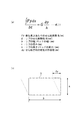
図1(a)、(b)に示されるように、工作機械に組み込まれるベッド1の上にはテーブル2が搭載されており、このテーブル2はベッド1の上をその長手方向(図中、x方向)に往復摺動可能とされている。ワーク(図示省略)はこのテーブル2の上にチャックなどの公知の手段により固定、支持された状態で図示を省略する工具により所望の加工が施される。この工具はベッド1に対して位置が固定されているので、加工中にワークに対して工具が作用する加工点Pは定位置となる。なお、この加工点Pはベッド1の長手方向における位置を示している。
ワークを加工している間に、ベッド1にはワーク及びテーブル2を介して、図1(b)に示すようにせん断荷重Fyが加工点Pに加わる。したがって、加工中にはベッド1にせん断変形δyが水平方向(図中、y方向)に生じようとする。第1実施形態はこのせん断変形に着目して、ベッド1に設けるリブ3の配置を設定する。
[First Embodiment]
Hereinafter, the present invention will be described in detail based on embodiments shown in the accompanying drawings.
As shown in FIGS. 1 (a) and 1 (b), a table 2 is mounted on a
While the workpiece is being processed, a shear load Fy is applied to the processing point P on the
ベッド1の幅方向に作用するせん断荷重Fyは、加工点Pを最大とする曲線状に分布する(図1(b)、(c)、(d))。このせん断荷重Fyは、通常、加工点Pに対して対称となる。なお、せん断荷重Fyの分布は、よく知られているように、ベッド1の仕様に基づいてFEM解析(有限要素法:Finite Element Method)などによって求めることができる。
The shear load Fy acting in the width direction of the
第1実施形態では、このせん断荷重Fyの分布に基づいて、リブ3の配置を以下のようにして特定する。ベッド1の幅方向に沿う複数のリブ3は、長手方向に間隔を空けてベッド1に配置されている。
(1)最大のせん断荷重Fyが作用する加工点Pに対応する位置x1にはリブ3を配置する(図1(c)、(d))。
(2)せん断荷重が作用する領域Aでは、各リブ3が受け持つせん断力が均等になるように、単位長さあたりのせん断荷重Fyを積分した値、つまりせん断応力τが予め設定される基準せん断応力τrに到達する位置にリブ3を配置する。つまり、位置x1を基準にしてせん断応力τが基準せん断応力τrに到達する位置x2に次のリブ3を配置し、次いで位置x2を基準にしてせん断応力τが基準せん断応力τrに到達する位置x3に次のリブ3を配置し、さらに位置x3を基準にしてせん断応力τが基準せん断応力τrに到達する位置x4に次のリブ3を配置する。なお、位置x3、位置x4は、位置x1を基準にすると、各々、せん断応力τが2×τrに到達する位置、せん断応力τが3×τrに到達する位置である。
つまり、x1の以降にリブ3が配置される位置xnは、位置xn−1を基準にして、せん断応力τが基準せん断応力τrに到達する位置となる。ただし、nは2以上の整数である。
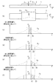
せん断応力τが基準せん断応力τrに到達するか否かは、図2(a)の式(1)に基づいて判断される。この式(1)において、左辺がせん断応力τを、また、右辺が基準せん断応力τrである。また、せん断方向の変位の許容値Δyは、工作機械の仕様により決定される値であるから、許容値Δyはベッド1が適用される機種によって異なるが、例えば10μmなどと設定される。
なお、加工点Pに対応する位置x1、せん断応力τが基準せん断応力τrに到達する位置x2、位置x3、位置4等に対して、若干の幅を持たせてリブ3を配置することを本発明は包含する。
(3)せん断応力τ(せん断荷重Fy)が作用しない領域Bにはリブ3を配置しない。
In the first embodiment, the arrangement of the
(1) The
(2) In the region A where the shear load is applied, a reference shear in which a value obtained by integrating the shear load Fy per unit length, that is, a shear stress τ, is set in advance so that the shear force of each
That is, the position xn where the
Whether the shear stress τ reaches the reference shear stress τr is determined based on the equation (1) in FIG. In this formula (1), the left side is the shear stress τ, and the right side is the reference shear stress τr. Further, since the allowable value Δy of the displacement in the shear direction is a value determined by the specifications of the machine tool, the allowable value Δy varies depending on the model to which the
It should be noted that the
(3) The
以上説明したように第1実施形態は、せん断荷重が作用する領域Aにおいて、加工点Pに近いほどリブ3の間隔を密にするというように、せん断荷重Fyの分布に基づいてリブ3の配置を設定する一方、せん断荷重が作用しない領域Bにはリブ3を配置しない。したがって、剛性を確保しつつ、最小限のリブ3の数でせん断変形を効率的に低減できるので、工作機械の軽量化に寄与する。
また、各リブ3が受け持つせん断応力τ(せん断荷重)を均等にすることで、せん断変形量をベッド1の長手方向に均等にできる。せん断変形が生じたとしても、せん断応力による変位量が均等であればワークの加工精度に悪影響を及ぼしにくいため、第1実施形態は加工精度向上に有利である。
As described above, in the first embodiment, in the region A where the shear load acts, the arrangement of the
Further, by equalizing the shear stress τ (shear load) which each
[第2実施形態]
以下、本発明による第2実施形態について説明する。
第2実施形態は、せん断荷重に加えてベッド1に加わる鉛直方向の荷重によるベッド1の鉛直方向の変形をも考慮して、リブ3の配置を設定する。せん断荷重については第1実施形態において説明したので、以下では鉛直荷重を中心にして説明する。
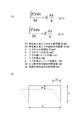
ワークを加工している間に、ベッド1にはワーク及びテーブル2を介して、図3(a)に示すように鉛直荷重Fz(及びせん断荷重Fy)が加工点Pに加わる。したがって、加工中にはベッド1に鉛直変形δz(及びせん断変形δy)が生じようとする。鉛直変形δzは、鉛直方向下向きの曲げ変形である。
ベッド1の厚さ方向に作用する鉛直荷重Fzは、加工点Pを最大とする曲線状に分布する(図3(a)、(d)、(f))。この鉛直荷重Fzは、通常、加工点Pに対して対称となる。なお、鉛直荷重Fzの分布は、よく知られているように、ベッド1の仕様に基づいてFEM解析などによって求めることができる。
[Second Embodiment]
Hereinafter, a second embodiment according to the present invention will be described.
In the second embodiment, the arrangement of the
While the workpiece is being processed, a vertical load Fz (and shear load Fy) is applied to the processing point P through the
The vertical load Fz acting in the thickness direction of the
第2実施形態では、この鉛直荷重Fz及びせん断荷重Fyの分布に基づいて、リブ3の配置を以下のようにして特定する。
(1)最大の鉛直荷重Fz及びせん断荷重Fyが作用する加工点Pに対応する位置z1(=x1)にはリブ3を配置する(図1(c)、(e))。
In the second embodiment, the arrangement of the
(1) The
(2)鉛直荷重Fz及びせん断荷重Fyが作用する領域は、各リブ3が受け持つ鉛直力及びせん断力が均等になるようにする。この場合、鉛直荷重に基づいて設定されるリブ3の配置位置と、せん断荷重に基づいて設定されるリブ3の配置位置と、を比較してリブ3を配置する位置が以下のようにして決定される。
単位長さあたりの鉛直荷重Fzを積分した値、つまり鉛直応力σが予め設定される基準鉛直応力σrに到達する位置を、リブ3を配置する候補とする。
鉛直応力σが基準鉛直応力σrに到達するか否かは、図4(a)の式(2)に基づいて判断される。この式(2)において、左辺が鉛直応力σを、また、右辺が基準鉛直応力σrである。また、鉛直方向の変位の許容値Δzは、工作機械の仕様により決定される値であるから、許容値Δzはベッド1が適用される機種によって異なるが、例えば10μmなどと設定される。
(2) In the region where the vertical load Fz and the shear load Fy are applied, the vertical force and the shear force that each
A value obtained by integrating the vertical load Fz per unit length, that is, a position where the vertical stress σ reaches a preset reference vertical stress σr is set as a candidate for arranging the
Whether or not the vertical stress σ reaches the reference vertical stress σr is determined based on the equation (2) in FIG. In this formula (2), the left side is the vertical stress σ, and the right side is the reference vertical stress σr. Further, since the allowable value Δz for the displacement in the vertical direction is a value determined by the specifications of the machine tool, the allowable value Δz varies depending on the model to which the
一方、せん断荷重Fyに関しては第1実施形態にて説明したのと同様に、位置x2がリブ3を配置する候補とする。
第2実施形態では、鉛直荷重(鉛直応力σ)に基づいて特定された位置z2と、せん断荷重(せん断応力τ)に基づいて特定された位置x2を比較し、位置x1(=z1)から近い位置x2の方が位置x1の次にリブ3を配置する位置に決定される。この場合、位置z2にはリブ3を配置しない。
On the other hand, with respect to the shear load Fy, as described in the first embodiment, the position x2 is a candidate for arranging the
In the second embodiment, the position z2 specified based on the vertical load (vertical stress σ) is compared with the position x2 specified based on the shear load (shear stress τ), and is close to the position x1 (= z1). The position x2 is determined as a position where the
(3)次に、リブを配置した位置x2を基準として、鉛直荷重に基づいて設定されるリブ3の配置位置と、せん断荷重に基づいて設定されるリブ3の配置位置と、を比較して次のリブ3を配置する位置が以下のようにして決定される。
リブを配置することを決定した位置x2を基準にして、鉛直応力σが予め設定される基準鉛直応力σrに到達する位置z3を、次のリブ3を配置する候補とする。
せん断荷重Fyに関しても同様に、リブ3を配置することを決定した位置x2を基準にして、せん断応力τが予め設定される基準せん断応力τrに到達する位置x3を、次のリブ3を配置する候補とする。
鉛直荷重(鉛直応力σ)に基づいて特定された位置z3と、せん断荷重(せん断応力τ)に基づいて特定された位置x3を比較し、位置x1(=z1)から近い位置z3の方が位置x2の次にリブ3を配置する位置に決定される。この場合、位置x3にはリブ3を配置しない。
以降、同様に、順次リブを配置することを決定した位置を基準として、次のリブ3が配置される位置が特定される。
つまり、位置x1の以降にリブが配置される位置は、位置(x,z)n−1を基準にして、せん断応力τが基準せん断応力τrに到達する位置xnと、鉛直応力σが基準鉛直応力σrに到達する位置znと、を比較し、位置(x,z)n−1に近い位置に特定される。ただし、nは2以上の整数である。
(4)鉛直応力σ(鉛直荷重Fz)及びせん断応力τ(せん断荷重Fy)が作用しない領域にはリブ3を配置しない。
(3) Next, with reference to the position x2 where the rib is arranged, the arrangement position of the
A position z3 at which the vertical stress σ reaches a preset reference vertical stress σr on the basis of the position x2 at which the rib is determined to be disposed is set as a candidate for disposing the
Similarly, with respect to the shear load Fy, the
The position z3 specified based on the vertical load (vertical stress σ) is compared with the position x3 specified based on the shear load (shear stress τ), and the position z3 closer to the position x1 (= z1) is the position. The position where the
Thereafter, similarly, the position at which the
That is, the position where the rib is arranged after the position x1 is the position xn where the shear stress τ reaches the reference shear stress τr with respect to the position (x, z) n−1 and the vertical stress σ is the reference vertical. The position zn reaching the stress σr is compared, and the position close to the position (x, z) n−1 is specified. However, n is an integer of 2 or more.
(4) The
以上説明した第2実施形態は、鉛直荷重をも考慮しているので、実際に生ずるであろう変形を反映したリブ3の配置を実現できる。
また第2実施形態は、鉛直荷重及びせん断荷重が作用する領域において、加工点Pに近いほどリブ3の間隔を密にするというように、鉛直荷重及びせん断荷重の分布に基づいてリブ3の配置を設定する一方、鉛直荷重及びせん断荷重が作用しない領域にはリブ3を配置しない。したがって、剛性を確保しつつ、最小限のリブ3の数で曲げ変形及びせん断変形を効率的に低減できるので、工作機械の軽量化に寄与する。
さらに第2実施形態は、各リブ3が受け持つせん断応力τ、鉛直応力を均等にすることで、加工精度向上にとってより有利である。
Since the second embodiment described above also takes into account the vertical load, the arrangement of the
In the second embodiment, the
Furthermore, the second embodiment is more advantageous for improving the machining accuracy by equalizing the shear stress τ and the vertical stress that each
なお、上記実施形態では幅方向に沿うリブ3のみを設けたベッド1を示したが、本発明は長手方向に沿うリブ3を設けることもできる。また、ベッド1の周縁には外枠を設けることができる。
これ以外にも、本発明の主旨を逸脱しない限り、上記実施の形態で挙げた構成を取捨選択したり、他の構成に適宜変更することが可能である。
In addition, although the
In addition to this, as long as it does not depart from the gist of the present invention, the configuration described in the above embodiment can be selected or changed to another configuration as appropriate.
1 ベッド
2 テーブル
3 リブ
1
Claims (4)
前記ベッドには幅方向に沿って複数のリブが前記長手方向に間隔を空けて配置され、
前記リブは、
工具が前記ワークに作用する加工点に対応する位置x1と、
位置xn−1(nは2以上の整数)を基準にして、前記工具が前記ワークに作用することにより前記ベッドに生ずるせん断応力τが、予め定められる基準せん断応力τrに到達する位置xnと、に基づいて、配置される、
ことを特徴とする工作機械のベッド。 A machine tool bed on which a table supporting a workpiece is mounted so as to be slidable back and forth along the longitudinal direction,
The bed has a plurality of ribs arranged in the longitudinal direction at intervals along the width direction,
The rib is
A position x1 corresponding to the machining point at which the tool acts on the workpiece;
Position x n-1 (n is an integer of 2 or more) with respect to the position x n the tool is the shear stress generated in said bed by acting on the workpiece τ is, to reach the reference shear stress τr be predetermined And arranged based on
Machine tool bed characterized by that.
前記ベッドには幅方向に沿って複数のリブが前記長手方向に間隔を空けて配置され、
前記リブは、
工具が前記ワークに作用する加工点に対応する位置x1と、
位置(x,z)n−1(nは2以上の整数)を基準にして、せん断応力τが基準せん断応力τrに到達する位置xnと、鉛直応力σが基準鉛直応力σrに到達する位置znと、を比較し、(x,z)n−1に近い位置xnまたは位置znに基づいて、配置される、
ことを特徴とする工作機械のベッド。 A machine tool bed on which a table supporting a workpiece is mounted so as to be slidable back and forth along the longitudinal direction,
The bed has a plurality of ribs arranged in the longitudinal direction at intervals along the width direction,
The rib is
A position x1 corresponding to the machining point at which the tool acts on the workpiece;
A position xn where the shear stress τ reaches the reference shear stress τr and a position zn where the vertical stress σ reaches the reference vertical stress σr with reference to the position (x, z) n−1 (n is an integer of 2 or more). And is arranged based on the position xn or the position zn close to (x, z) n−1 .
Machine tool bed characterized by that.
請求項1に記載の工作機械のベッド。 In the region where the shear stress τ does not act, the rib is not disposed.
The bed of the machine tool according to claim 1.
請求項2に記載の工作機械のベッド。 In the region where the shear stress τ and the vertical stress σ do not act, the rib is not disposed.
The machine tool bed according to claim 2.
Priority Applications (1)
| Application Number | Priority Date | Filing Date | Title |
|---|---|---|---|
| JP2011029593A JP5695931B2 (en) | 2011-02-15 | 2011-02-15 | Machine tool bed |
Applications Claiming Priority (1)
| Application Number | Priority Date | Filing Date | Title |
|---|---|---|---|
| JP2011029593A JP5695931B2 (en) | 2011-02-15 | 2011-02-15 | Machine tool bed |
Publications (2)
| Publication Number | Publication Date |
|---|---|
| JP2012166310A true JP2012166310A (en) | 2012-09-06 |
| JP5695931B2 JP5695931B2 (en) | 2015-04-08 |
Family
ID=46970983
Family Applications (1)
| Application Number | Title | Priority Date | Filing Date |
|---|---|---|---|
| JP2011029593A Expired - Fee Related JP5695931B2 (en) | 2011-02-15 | 2011-02-15 | Machine tool bed |
Country Status (1)
| Country | Link |
|---|---|
| JP (1) | JP5695931B2 (en) |
Citations (4)
| Publication number | Priority date | Publication date | Assignee | Title |
|---|---|---|---|---|
| JPS5645306A (en) * | 1979-09-12 | 1981-04-25 | Hitachi Seiko Ltd | Structure of bed in machine tool |
| JP2007296602A (en) * | 2006-04-28 | 2007-11-15 | Nippei Toyama Corp | Machine tool bed |
| JP2009179318A (en) * | 2009-05-18 | 2009-08-13 | Kawasaki Heavy Ind Ltd | Railcar structures |
| CN101811257A (en) * | 2010-04-23 | 2010-08-25 | 上海理工大学 | Optimal machine tool body structure design method |
-
2011
- 2011-02-15 JP JP2011029593A patent/JP5695931B2/en not_active Expired - Fee Related
Patent Citations (4)
| Publication number | Priority date | Publication date | Assignee | Title |
|---|---|---|---|---|
| JPS5645306A (en) * | 1979-09-12 | 1981-04-25 | Hitachi Seiko Ltd | Structure of bed in machine tool |
| JP2007296602A (en) * | 2006-04-28 | 2007-11-15 | Nippei Toyama Corp | Machine tool bed |
| JP2009179318A (en) * | 2009-05-18 | 2009-08-13 | Kawasaki Heavy Ind Ltd | Railcar structures |
| CN101811257A (en) * | 2010-04-23 | 2010-08-25 | 上海理工大学 | Optimal machine tool body structure design method |
Also Published As
| Publication number | Publication date |
|---|---|
| JP5695931B2 (en) | 2015-04-08 |
Similar Documents
| Publication | Publication Date | Title |
|---|---|---|
| EA200800702A1 (en) | FORMING TOOL | |
| KR20120084909A (en) | A high-rigidity multipurpose manufacturing device | |
| JP5967049B2 (en) | Press equipment, production line | |
| JP6389618B2 (en) | Machine tool guide for machine tools | |
| CN102172681B (en) | A kind of bender lower die anti-deflection device and processing method thereof | |
| JP5695931B2 (en) | Machine tool bed | |
| JP2004291065A (en) | Sequential forming method and apparatus | |
| JP4955489B2 (en) | Bending machine | |
| JP2013215752A (en) | Incremental forming method of metal plate | |
| CN104289861B (en) | Long rod piece machining method and auxiliary tool for long rod piece machining | |
| CN105108502A (en) | Stand-column-reinforced precise vertical machining center | |
| BR102018012712A2 (en) | METAL MEMBER MANUFACTURING METHOD | |
| MX2014010039A (en) | Machine and method for treating cast components. | |
| CN101885022B (en) | Combined oil press with stander shared by punching and stretching | |
| TW201701988A (en) | Dual-head multipurpose machine tool having stable structure and enhancing machine precision, prolonging service life of the machine, and effectively enhancing machining efficiency | |
| CN202137385U (en) | Closed lathe bed with four guide rails in steel inserted structure for turning lathe | |
| CN210649556U (en) | Clamp platform of numerical control machine tool | |
| CN103846685A (en) | Light weight full-symmetry machine tool spindle ram with stable thermal structure | |
| KR101248898B1 (en) | Cross-rail bending compensation method and apparatus | |
| JP6945740B2 (en) | Roll stand | |
| JP2022097299A (en) | Design device | |
| CN201702250U (en) | Combined type oil press of rack commonly used by punching and drawing | |
| JP2012130955A (en) | Mechanism for holding parallelism of die | |
| CN205289509U (en) | Aluminum plate is adjusting device for punching press | |
| KR20160049335A (en) | Machine tool |
Legal Events
| Date | Code | Title | Description |
|---|---|---|---|
| A621 | Written request for application examination |
Free format text: JAPANESE INTERMEDIATE CODE: A621 Effective date: 20131118 |
|
| A977 | Report on retrieval |
Free format text: JAPANESE INTERMEDIATE CODE: A971007 Effective date: 20140821 |
|
| A131 | Notification of reasons for refusal |
Free format text: JAPANESE INTERMEDIATE CODE: A131 Effective date: 20140827 |
|
| A521 | Written amendment |
Free format text: JAPANESE INTERMEDIATE CODE: A523 Effective date: 20141020 |
|
| TRDD | Decision of grant or rejection written | ||
| A01 | Written decision to grant a patent or to grant a registration (utility model) |
Free format text: JAPANESE INTERMEDIATE CODE: A01 Effective date: 20150114 |
|
| A61 | First payment of annual fees (during grant procedure) |
Free format text: JAPANESE INTERMEDIATE CODE: A61 Effective date: 20150209 |
|
| R151 | Written notification of patent or utility model registration |
Ref document number: 5695931 Country of ref document: JP Free format text: JAPANESE INTERMEDIATE CODE: R151 |
|
| S111 | Request for change of ownership or part of ownership |
Free format text: JAPANESE INTERMEDIATE CODE: R313111 |
|
| R350 | Written notification of registration of transfer |
Free format text: JAPANESE INTERMEDIATE CODE: R350 |
|
| LAPS | Cancellation because of no payment of annual fees |