JP2012166301A - Press-fitting device - Google Patents
Press-fitting device Download PDFInfo
- Publication number
- JP2012166301A JP2012166301A JP2011028966A JP2011028966A JP2012166301A JP 2012166301 A JP2012166301 A JP 2012166301A JP 2011028966 A JP2011028966 A JP 2011028966A JP 2011028966 A JP2011028966 A JP 2011028966A JP 2012166301 A JP2012166301 A JP 2012166301A
- Authority
- JP
- Japan
- Prior art keywords
- press
- fitting
- arm
- shank
- jig
- Prior art date
- Legal status (The legal status is an assumption and is not a legal conclusion. Google has not performed a legal analysis and makes no representation as to the accuracy of the status listed.)
- Withdrawn
Links
Images
Landscapes
- Automatic Assembly (AREA)
Abstract
【課題】圧入時に工作機械に大きな負荷がかかることを確実に防止できる圧入装置を提供する。
【解決手段】主軸11の回動に伴って一体的に回動するシャンク30と、シャンク30を回動可能に支持する支持部材40と、シャンク30の回動に伴って一体的に回動する推進部材50と、推進部材50が回動した際に、推進部材50をシャンク30に対して前後方向に相対的に移動可能に支持するとともに、皿ばね75・75を介して支持部材40に支持されるアーム70と、推進部材50の移動に伴って一体的に移動するとともに、圧入部品W1を支持する圧入ヘッド60と、を具備する圧入工具20を主軸11に装着し、アーム70が後方向に移動不能となるようにアーム70の係合部70dを治具100の切欠部100aに係合させた状態で、圧入装置1を後方向に移動させて、支持部材40をアーム70から離間させた状態で、圧入部品W1をワークWに対して圧入する。
【選択図】図4A press-fitting device that can reliably prevent a heavy load on a machine tool during press-fitting is provided.
A shank 30 that rotates integrally with rotation of a main shaft 11, a support member 40 that rotatably supports the shank 30, and a rotation that rotates integrally with the rotation of the shank 30. When the propelling member 50 and the propelling member 50 are rotated, the propelling member 50 is supported so as to be movable relative to the shank 30 in the front-rear direction, and supported by the support member 40 via the disc springs 75 and 75. The press-fit tool 20 having the arm 70 and the press-fit head 60 that supports the press-fit component W1 and moves integrally with the movement of the propelling member 50 is attached to the main shaft 11, and the arm 70 moves backward. In a state where the engaging part 70d of the arm 70 is engaged with the notch part 100a of the jig 100 so that it cannot be moved to the position, the press-fitting device 1 is moved backward to separate the support member 40 from the arm 70. In the state Press-fitting the input parts W1 with respect to the workpiece W.
[Selection] Figure 4
Description
本発明は、圧入部品をワークに対して圧入する圧入装置に関する。 The present invention relates to a press-fitting device for press-fitting a press-fitting part into a workpiece.
従来から、圧入装置を用いてコンロッド等のワークにピン等の圧入部品を圧入している。このような圧入装置は、例えば、圧入部品を支持する圧入ヘッドを、シリンダの駆動によってワークに接近させ、治具に支持される圧入部品をワークに対して圧入する。 Conventionally, press-fitting parts such as pins are press-fitted into a work such as a connecting rod using a press-fitting device. In such a press-fitting device, for example, a press-fitting head that supports press-fitting parts is brought closer to the work by driving the cylinder, and the press-fitting parts supported by the jig are press-fitted into the work.
この場合、圧入時の反力(圧入反力)を圧入装置全体で受けることとなるため、圧入装置は圧入反力に耐えられるような、大型な装置となってしまう。
また、圧入装置は、ある決まった形状のワークの、所定の圧入位置に圧入するだけの装置、つまり、ある形状のワーク専用の圧入装置である。従って、圧入位置やワークの形状が変更となった場合、当該変更に対応できず、別の圧入装置が必要となる場合があった。つまり、汎用性が低かった。
In this case, since the reaction force at the time of press-fitting (press-fitting reaction force) is received by the entire press-fitting device, the press-fitting device becomes a large device that can withstand the press-fitting reaction force.
The press-fitting device is a device that only press-fits a workpiece having a predetermined shape into a predetermined press-fitting position, that is, a press-fitting device dedicated to a workpiece having a certain shape. Therefore, when the press-fitting position and the shape of the workpiece are changed, the change cannot be dealt with, and another press-fitting device may be required. That is, the versatility was low.
特許文献1に開示される圧入装置は、マシニングセンタの主軸に連結され、スラスト吸収機構および圧入反力相殺機構等を具備する。スラスト吸収機構は、二つの回転部材をスプリングによって連結し、一方の回転部材を他方の回転部材よりスラスト方向に移動させることで、主軸に作用するスラストを吸収する。圧入反力相殺機構は、主軸の回転により回転する正ネジ部分および逆ネジ部分に、圧入部品を支持するナット部を螺合することで構成される。
The press-fitting device disclosed in
このような特許文献1に開示される圧入装置は、主軸の回転によりナット部を圧入方向に移動させ、圧入部品をワークに対して圧入する。このとき、正ネジ部分と螺合するナット部と逆ネジ部分と螺合するナット部とは、互いに反対方向に移動しながら圧入部品を圧入する。
つまり、正ネジ部と逆ネジ部とで互いに反対方向に作用する圧入反力を相殺させることで、主軸に作用するスラストを軽減する。仮に、圧入反力を相殺しきれなかった場合には、スラスト吸収機構が主軸に作用するスラストを吸収する。
In such a press-fitting device disclosed in
In other words, the thrust acting on the main shaft is reduced by canceling the press-fitting reaction forces acting in opposite directions between the normal screw portion and the reverse screw portion. If the press-fitting reaction force cannot be offset, the thrust absorbing mechanism absorbs the thrust acting on the main shaft.
このような特許文献1に開示される圧入装置では、相殺しきれなかった圧入反力が大きい場合、マシニングセンタに大きな負荷がかかる可能性がある。
また、スラスト吸収機構や圧入反力相殺機構等により圧入荷重が吸収されるため、圧入荷重の測定が困難となってしまう。
In such a press-fitting device disclosed in
Further, since the press-fit load is absorbed by a thrust absorbing mechanism, a press-fit reaction force canceling mechanism, etc., it becomes difficult to measure the press-fit load.
本発明は、以上の如き状況を鑑みてなされたものであり、圧入時に工作機械に大きな負荷がかかることを確実に防止できる圧入装置を提供するものである。 The present invention has been made in view of the above situation, and provides a press-fitting device that can reliably prevent a heavy load on a machine tool during press-fitting.
請求項1においては、回動可能な主軸に圧入工具を装着し、前記圧入工具に支持される圧入部品を治具に支持されるワークに対して圧入する圧入装置であって、前記圧入工具は、前記主軸に連結され、前記主軸の回動に伴って一体的に回動するシャンクと、前記シャンクを回動可能に支持する支持部材と、前記シャンクに連結され、前記シャンクの回動に伴って一体的に回動する推進部材と、前記推進部材が回動した際に、前記推進部材を前記シャンクに対して圧入方向に相対的に移動可能に支持するとともに、弾性部材を介して前記支持部材に支持され、前記圧入方向と反対側の方向に移動不能となるように前記治具に係合する係合部が形成されるアームと、前記推進部材に連結され、前記推進部材の移動に伴って一体的に移動するとともに、前記圧入部品を支持する圧入ヘッドと、を具備し、前記圧入装置は、前記アームの係合部を前記治具に係合させた状態で、前記圧入方向と反対側の方向に移動することで前記弾性部材を弾性変形させて、前記支持部材を前記アームから離間させ、該支持部材とアームとの離間状態を保持した状態で、前記主軸の回動により前記推進部材を回動させて、前記推進部材を前記シャンクに対して相対的に前記圧入方向に移動させることにより、前記圧入部品を前記ワークに対して圧入する、ものである。
The press-fitting device according to
請求項2においては、前記圧入工具は、前記アームまたは前記治具に取り付けられ、前記支持部材を前記アームから離間させたときに前記アームまたは前記治具にかかる荷重、および圧入時に前記治具または前記アームにかかる荷重を測定する測定手段をさらに具備し、前記圧入装置は、前記測定手段の前記各測定結果に基づいて、前記圧入部品の圧入荷重を測定する、ものである。 In Claim 2, The said press-fit tool is attached to the said arm or the said jig | tool, The load applied to the said arm or the said jig | tool when the said supporting member is spaced apart from the said arm, and the said jig | tool or The apparatus further comprises measurement means for measuring a load applied to the arm, and the press-fitting device measures a press-fit load of the press-fitting part based on the measurement results of the measurement means.
本発明は、工作機械に圧入反力が伝播することを防止できるため、圧入時に工作機械に大きな負荷がかかることを確実に防止できるという効果を奏する。 The present invention can prevent the press-fitting reaction force from propagating to the machine tool, so that it is possible to reliably prevent a large load from being applied to the machine tool during press-fitting.
以下では、本実施形態の圧入装置1について、図面を参照して説明する。
Below, the
なお、以下では、説明の便宜上図1における紙面の左右方向を基準として「圧入装置1の左右方向」を規定する。また、図1における紙面の上側から下側へ向かう方向を前方向として「圧入装置1の前後方向」を規定する。
In the following, for convenience of explanation, the “left-right direction of the press-
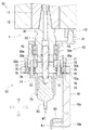
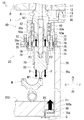
図1に示すように、圧入装置1は、回動可能な主軸11に圧入工具20を装着することで構成され、圧入部品W1をワークWに対して圧入するものである。このような主軸11は、例えば、市販の工作機械(例えば、一軸NC加工機等)の主軸により構成される。
圧入装置1は、工作機械10に設けられ、工作機械10の主軸11を移動させる移動機構により、所望の位置に移動可能である。
As shown in FIG. 1, the press-
The press-
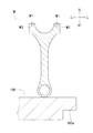
なお、本実施形態では、図2に示すように、ワークWをコンロッドとし、圧入部品W1としてのピンを、コンロッドの大端側に形成される穴部W2に対して圧入するものとするが、これに限定されるものでない。 In this embodiment, as shown in FIG. 2, the workpiece W is a connecting rod, and the pin as the press-fitting component W1 is press-fitted into the hole W2 formed on the large end side of the connecting rod. It is not limited to this.
圧入工具20は、主軸11の回転を利用して、前端部で支持する圧入部品W1をワークWに対して圧入するものである(図5参照)。図1に示すように、圧入工具20は、シャンク30、支持部材40、推進部材50、圧入ヘッド60、アーム70、およびロードセル80等を具備する。
The press-
シャンク30は、中空状の部材であり、その後端部が主軸11に連結され、主軸11に回動に伴って一体的に回動する。
The
シャンク30の前端部には、その内径が部分的に小さくなっている部分があり、当該内径が小さい部分に二つのキー溝30a・30aが形成される。
各キー溝30a・30aは、それぞれ前後方向から見たときに略四角形状となる窪みである。各キー溝30a・30aは、互いに180°位相をずらしたような位置関係となる。
The front end portion of the
Each of the
支持部材40は、シャンク30の前側を覆う略筒状の部材であり、その中空部分にシャンク30を支持するベアリング42・42等が嵌装される。支持部材40は、その後端部が右方向に延出する。支持部材40は、前記延出部分にて、工作機械10のハウジング12に設けられる固定部材13に、位置決めピン41を介して回動不能に固定される。
The
つまり、支持部材40は、位置決めピン41を回り止めとして機能させ、シャンク30を回動可能に支持する。また、支持部材40とアーム70とを連結するボルト74・74の位相を決めることで、後述するアーム70の突出部70cの位相を決める。
That is, the
推進部材50は、略円柱状の部材であり、その後端部がシャンク30の前側に連結されるとともに、その前端部が圧入ヘッド60の後端部に連結される。
The
推進部材50の後端部には、前後方向から見たときに各キー溝30a・30aと略同一形状および同一位相となる二つの突起部50a・50aが形成される。各突起部50a・50aの前後方向の寸法は、それぞれ各キー溝30a・30aの前後方向の寸法よりも短くなる。
各突起部50a・50aを各キー溝30a・30aに嵌合させることにより、推進部材50は、シャンク30の回動に伴って一体的に回動する。
Two
By fitting the
推進部材50の前後中途部には、後述するアーム70の雌ネジ部70bと螺合する雄ネジ部50bが形成される。
A
推進部材50の前端部は、後述するアーム70の基部70aより前方向に突出する。
The front end portion of the propelling
圧入ヘッド60は、その前端部で圧入部品W1を支持する(図1に二点鎖線で示す圧入部品W1参照)。圧入ヘッド60は、推進部材50の前後方向の移動に伴って一体的に移動するとともに、推進部材50の回動に伴って一体的に回動しないように、複数のボール51・51・・・・・・を介して推進部材50に連結される。
The press-fitting
推進部材50の前後方向への移動が一定の範囲を超えたとき、各突起部50a・50aが各キー溝30a・30aから外れ、推進部材50が回動しなくなる(主軸11およびシャンク30が空回りする)。
When the forward and backward movement of the
これにより、主軸11の回り過ぎによる推進部材50および圧入ヘッド60の過剰な前後方向への移動を規制する。
すなわち、過剰な前方向への移動により、雄ネジ部50bが雌ネジ部70bよりも前方向へ移動して、推進部材50がアーム70から抜け落ちてしまうこと等を防止する。
Thereby, excessive movement in the front-rear direction of the
That is, it is possible to prevent the
アーム70には、基部70a、雌ネジ部70b、突出部70c、および係合部70dが形成される。
The
基部70aは、左右中心部に前後方向に貫通する孔部が形成される略円板状の部材である。基部70aの後側面には、ボルト72・72を介して略筒状の後側ガイド部材71が取り付けられる。基部70aの前側面の左右中心部には、略筒状の前側ガイド部材73が取り付けられる。
The
雌ネジ部70bは、基部70aの左右中心部を前後方向に貫通する孔部に形成され、推進部材50の雄ネジ部50bと螺合する。
The
すなわち、アーム70は、推進部材50が回動した際に、その回動方向に応じて、推進部材50をシャンク30に対して前方向または後方向に相対的に移動可能なように支持する。
That is, when the propelling
突出部70cは、基部70aの前側面の右側より前方向に突出する部分である。
The protruding
係合部70dは、突出部70cの前端部より左方向に突出する部分である。係合部70dの後側面には、ロードセル80が取り付けられる。
The
このようなアーム70は、ボルト74・74を介して支持部材40に支持される。また、ボルト74・74とアーム70との間には、それぞれ二つの皿ばね75・75(弾性部材)および座金76が介在する。つまり、アーム70は、各皿ばね75・75を介して支持部材40に支持される。
Such an
ロードセル80は、圧入時の荷重(圧入部品W1の圧入荷重F、図5参照)を測定するためのものであり、アーム70にかかる荷重を測定する。ロードセル80は、配線81を介して所定の制御装置に測定値を送信可能に構成される。このようなロードセル80は、市販のロードセルが用いられる。
The
次に、圧入装置1によるワークWへの圧入部品W1の圧入動作について説明する。
Next, the press-fitting operation of the press-fitting component W1 into the workpiece W by the press-fitting
まず、図2に示すように、ワークWを治具100にセットする。これにより、ワークWは、治具100に所定の姿勢で支持される。治具100には、その後側面の右側に切欠部100aが形成される。
この時点において、ワークWと圧入装置1とは、互いに離間している。
First, as shown in FIG. 2, the workpiece W is set on the
At this time, the workpiece W and the press-fitting
ワークWを治具100にセットした後で、圧入ヘッド60に圧入部品W1をセットする(図1に二点鎖線で示す圧入部品W1参照)。
After the workpiece W is set on the
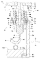
圧入ヘッド60に圧入部品W1をセットした後で、図3に示すように、工作機械10の移動機構により、主軸11および圧入工具20(つまり、圧入装置1)を治具100の近傍へ移動させる。このとき、アーム70の係合部70dの後側面は、ロードセル80を介して治具100の切欠部100aの前側面に当接する。
After the press-fitting part W1 is set in the press-fitting
アーム70の突出部70cの前方向への突出寸法および係合部70dの左方向への突出寸法等は、それぞれ適宜の長さに設定されている。従って、この時点で、圧入部品W1の前方にワークWの穴部W2が位置する。
The projecting dimension of the projecting
圧入装置1を治具100の近傍へ移動させた後で、工作機械10の移動機構により、圧入装置1を後方向に移動させる(図3に示す符号P参照)。
このとき、アーム70の係合部70dが治具100の切欠部100aに引っ掛かるため、工作機械10の主軸11は、圧入工具20を後方向に引っ張ることとなる。
After the press-fitting
At this time, since the engaging
このとき、図3および図4に示すように、支持部材40は、各皿ばね75・75を圧縮しながら(各皿ばね75・75を弾性変形させながら)、後側ガイド部材71に沿って、アーム70に対して相対的に後方向に移動する。また、シャンク30も後方向に移動する。
一方、推進部材50および圧入ヘッド60は、それぞれ後方向に移動しない。
At this time, as shown in FIGS. 3 and 4, the
On the other hand, the
これにより、支持部材40とアーム70との間にクリアランスCが形成される。すなわち、圧入装置1は、後方向に移動することで、支持部材40をアーム70から離間させる。つまり、主軸11をアーム70から分離させる。
Thereby, a clearance C is formed between the
このように、アーム70の係合部70dは、アーム70が後方向に移動不能となるように、治具100の切欠部100aに係合する。
Thus, the engaging
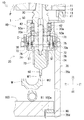
支持部材40をアーム70から離間させた後で、図4および図5に示すように、主軸11を回動させる(図5に示す符号R参照)。これにより、推進部材50を回動させ、推進部材50を前方向に移動させる。このとき、推進部材50は、前側ガイド部材73に沿って、シャンク30に対して相対的に前方向に移動する。
推進部材50の前方向への移動に伴い、圧入ヘッド60がワークWの穴部W2に接近し、圧入部品W1がワークWに対して圧入される。
After the
As the
圧入時には、工作機械10が移動機構により後方向へ移動された状態を保持している(図4および図5に示す符号P参照)。
つまり、圧入装置1は、支持部材40とアーム70との離間状態を保持した状態で圧入部品W1をワークWに対して圧入する。
At the time of press-fitting, the
That is, the press-fitting
以上のように、本実施形態では、前方向が圧入方向となり、後方向が圧入方向と反対側の方向となる。 As described above, in the present embodiment, the front direction is the press-fitting direction, and the rear direction is the direction opposite to the press-fitting direction.
このように圧入装置1を構成することにより、主軸11の回転トルクを圧入ヘッド60の推進力に変換して、圧入部品W1をワークWに対して圧入できる。
これによれば、小さな回転トルクで大きな推進力を生み出すことができる。つまり、小さな容量のモータを搭載した小型の工作機械10でも、圧入するために必要な推進力(圧入荷重F)を生み出すことができる。
By configuring the press-fitting
According to this, a large driving force can be generated with a small rotational torque. That is, even a
圧入時には、治具100に作用する圧入時の反力(圧入反力F1)が、アーム70の係合部70dから突出部70cに伝播し、その後に基部70aに伝播する(図5に示す伝播した圧入反力F2参照)。
At the time of press-fitting, a reaction force (press-fitting reaction force F1) that acts on the
基部70aに伝播した圧入反力F2は、支持部材40等に伝播しようとするが、支持部材40とアーム70とが離間状態にあるため、支持部材40に伝播できない(図4に示すクリアランスC参照)。従って、圧入反力F1は、アーム70および治具100に対して作用する。
The press-fitting reaction force F2 propagated to the
ここで、小型の工作機械10は、耐荷重許容値が小さいため、圧入時に発生する圧入反力F1が工作機械10に作用した場合、当該圧入反力F1に耐えられない可能性がある。
Here, since the
つまり、圧入時に支持部材40とアーム70とが離間状態になく、基部70aに伝播した圧入反力F2が支持部材40に伝播してしまう場合には、圧入反力F1に耐えられるような、大型の工作機械10を用いる必要がある。これは、アーム70を用いずに、主軸11の回転トルクを圧入ヘッド60の推進力に変換し、圧入部品W1をワークWに対して圧入する場合においても同様である。
That is, when the
このような構成では、小型の工作機械10の主軸11で圧入荷重Fを生み出せることができるにも関わらず、圧入反力F1の影響で、小型の工作機械10を用いることができない。
In such a configuration, although the press-fit load F can be generated by the
つまり、本実施形態の圧入装置1のように、支持部材40をアーム70から離間させるとともに、当該離間状態を保持した状態で、圧入部品W1を圧入する構成とすることで、小型の工作機械10を用いることができるのである。
That is, as in the press-fitting
また、工作機械10に圧入反力F2が伝播することを防止できるため、圧入時に工作機械10に大きな負荷がかかることを確実に防止できる。
Further, since the press-fitting reaction force F2 can be prevented from propagating to the
仮に、圧入位置やワークWの形状が変更となった場合には、圧入工具20の取替えや圧入装置1の移動位置の変更を行うことにより、容易に対応できる。
If the press-fitting position or the shape of the workpiece W is changed, it can be easily handled by replacing the press-fitting
また、圧入装置1が設置される生産設備での大幅な仕様変更、例えば、生産するものが変更となり、工作機械10で圧入に代えて切削を行う場合等にも、圧入工具20を切削用の工具に取り替えることにより、容易に対応できる。
In addition, the press-
すなわち、圧入装置1は、圧入工具20を主軸11に装着する構成とすることで、圧入位置、ワークWの形状、および機械加工等の変更に容易に対応できる。つまり、圧入装置1の汎用性を向上できる。
That is, the press-fitting
なお、各皿ばね75・75の付勢力は、必要最小限に設定することが望ましい。
すなわち、各皿ばね75・75の付勢力が小さ過ぎる場合には、アーム70の自重によって、アーム70が支持部材40から離間してしまう。
また、各皿ばね75・75の付勢力が大き過ぎる場合には、支持部材40をアーム70から離間させる際に要する力(工作機械10の引っ張り力)が大きくなってしまう。
In addition, it is desirable to set the urging force of the disc springs 75 and 75 to the minimum necessary.
That is, when the urging force of the disc springs 75 and 75 is too small, the
Moreover, when the urging | biasing force of each
従って、各皿ばね75・75の付勢力は、アーム70の自重によってアーム70が支持部材40から離間しない程度の大きさ(必要最小限の大きさ)であることが望ましい。
Therefore, it is desirable that the urging force of the disc springs 75 and 75 has such a magnitude (minimum necessary size) that the
ここで、圧入部品W1の圧入においては、個々の圧入部品W1の形状およびワークWの穴部W2の形状の違いにより、圧入部品W1の圧入荷重Fの大きさが変動する。 Here, in the press-fitting of the press-fit component W1, the magnitude of the press-fit load F of the press-fit component W1 varies depending on the shape of each press-fit component W1 and the shape of the hole W2 of the workpiece W.
具体的には、圧入部品W1の形状がワークWの穴部W2に対して小さい場合やワークWの穴部W2の形状が圧入部品W1に対して大きい場合には、圧入部品W1を穴部W2に押し込み易くなり、圧入荷重Fが小さくなる。
また、圧入部品W1の形状がワークWの穴部W2に対して大きい場合やワークWの穴部W2の形状が圧入部品W1に対して小さい場合には、圧入部品W1を穴部W2に押し込み難くなり、圧入荷重Fが大きくなる。
Specifically, when the shape of the press-fit component W1 is smaller than the hole W2 of the workpiece W or when the shape of the hole W2 of the workpiece W is larger than the press-fit component W1, the press-fit component W1 is replaced with the hole W2. And the press-fit load F becomes small.
Further, when the shape of the press-fit part W1 is larger than the hole W2 of the workpiece W or when the shape of the hole W2 of the work W is smaller than the press-fit part W1, it is difficult to push the press-fit part W1 into the hole W2. Thus, the press-fit load F increases.
仮に、圧入荷重Fが小さ過ぎる場合、圧入後にワークWの穴部W2から圧入部品W1が抜けてしまう可能性がある。 If the press-fitting load F is too small, the press-fitting component W1 may come out from the hole W2 of the workpiece W after press-fitting.
このため、圧入時に圧入荷重Fを測定し、予め設定される圧入荷重Fの範囲内であるか(例えば、所定の閾値以上の測定値であるか等)を確認する必要がある。 For this reason, it is necessary to measure the press-fitting load F at the time of press-fitting and confirm whether it is within a preset press-fitting load F (for example, a measured value equal to or greater than a predetermined threshold).
本実施形態の圧入装置1では、ロードセル80の測定値に基づいて、圧入荷重Fを測定している。
In the press-fitting
すなわち、本実施形態では、前述のように、支持部材40とアーム70との離間状態を保持した状態で圧入を行う。このため、圧入荷重Fの測定においては、支持部材40をアーム70から離間させたときにアーム70にかかる荷重を考慮する。
つまり、圧入装置1は、圧入時の測定値(図5における測定値)から、支持部材40をアーム70から離間させたときの測定値(図4における測定値)を差し引き、その算出値を圧入荷重Fとしている。
That is, in the present embodiment, as described above, press-fitting is performed in a state in which the
That is, the press-fitting
ここで、アーム70の剛性および表面硬さと、主軸11の軸心位置に対するロードセル80の位置の半径方向のズレ(以下、「オフセット量G」と表記する)とが、圧入荷重Fの測定精度に影響を与える可能性がある。
Here, the rigidity and surface hardness of the
具体的には、アーム70の剛性および表面硬さが低い場合、アーム70が変形して、アーム70にかかる荷重をアーム70自身が吸収してしまう可能性がある。
この場合、ロードセル80の測定値に、前記吸収した荷重が反映されることとなり、単に図5における測定値から図4における測定値を差し引くだけでは圧入荷重Fを正確に測定できなくなる。
Specifically, when the rigidity and surface hardness of the
In this case, the absorbed load is reflected in the measured value of the
本実施形態では、圧入時にアーム70が変形しないような、剛性および表面硬さを有する金属部材等でアーム70を形成している。
従って、圧入時にアーム70が変形することはなく、アーム70の変形による測定値の変動を考慮する必要はない。
In the present embodiment, the
Therefore, the
また、主軸11とロードセル80とのオフセット量Gが大きい場合、アーム70に回転モーメントが発生し、アーム70にかかる荷重をアーム70自身が吸収してしまう可能性がある。
Further, when the offset amount G between the
本実施形態では、圧入時に回転モーメントが発生しないようなオフセット量Gとなるように、主軸11とロードセル80との位置関係を調整している。
従って、圧入時に回転モーメントが発生することはなく、回転モーメントによる測定値の変動を考慮する必要はない。
In the present embodiment, the positional relationship between the
Therefore, no rotational moment is generated at the time of press-fitting, and it is not necessary to consider the variation of the measured value due to the rotational moment.
つまり、圧入装置1は、単に図5における測定値から図4における測定値を差し引くだけで圧入荷重Fを正確に測定できる。
That is, the press-fitting
このように、アーム70および治具100にて圧入反力F1を受ける構成とすることで、圧入荷重Fを容易に測定することが可能となる。
As described above, the press-fit load F can be easily measured by receiving the press-fit reaction force F1 with the
仮に、測定した圧入荷重Fが予め設定される範囲外である場合、制御装置により異常を検出し、圧入装置1が設置される生産設備等の動作を停止する。そして、異常が検出されたワークWを取り除き、生産設備の動作を再開する。
If the measured press-fitting load F is outside the preset range, an abnormality is detected by the control device, and the operation of the production facility where the press-fitting
圧入荷重Fの測定においては、主軸11の回転トルクに基づいて圧入荷重Fを算出することが考えられるが、本実施形態の圧入装置1のように回転トルクを圧入ヘッド60の推進力に変換する構成である場合、主軸11の回転トルクは小さい。
従って、圧入荷重Fの変動度合いが大きい場合でも、主軸11の回転トルクの変動度合いは小さくなってしまう。つまり、精度よく圧入荷重Fを測定できない可能性がある。
In the measurement of the press-fit load F, it is conceivable to calculate the press-fit load F based on the rotational torque of the
Therefore, even when the variation degree of the press-fit load F is large, the variation degree of the rotational torque of the
一方、本実施形態の圧入装置1のように、アーム70にかかる荷重をロードセル80によってダイレクトに測定することで、圧入荷重Fの変動を確実に測定できる。つまり、圧入装置1は、主軸11の回転トルクに基づいて圧入荷重Fを測定する場合と比較して、より高精度に圧入荷重Fを測定できる。
On the other hand, by directly measuring the load applied to the
なお、正確に圧入荷重Fを測定できるという観点より、オフセット量Gは0であることが望ましい。つまり、圧入装置1を前後方向から見たときに、主軸11の軸心とロードセル80とが互いに重なる位置関係にある(主軸11の軸心とロードセル80とが互いに同軸上にある)ことが望ましい。
仮に、オフセット量Gが0より大きくなる場合、オフセット量Gは、極力小さいことが望ましい。
Note that the offset amount G is desirably 0 from the viewpoint that the press-fit load F can be accurately measured. In other words, when the press-fitting
If the offset amount G is greater than 0, it is desirable that the offset amount G is as small as possible.
本実施形態では、ロードセル80は、アーム70の係合部70dに取り付けられる構成としたが、これに限定されるものでない。すなわち、ロードセル80は、圧入荷重Fを測定可能な位置に配置されていればよく、例えば、治具100の切欠部100aに取り付けられて、治具100にかかる荷重を測定する構成であっても構わない。
In the present embodiment, the
このように、ロードセル80は、アーム70または治具100に取り付けられ、支持部材40をアーム70から離間させたときにアーム70または治具100にかかる荷重、および圧入時にアーム70または治具100にかかる荷重を測定する測定手段として機能する。
As described above, the
1 圧入装置
11 主軸
20 圧入工具
30 シャンク
40 支持部材
50 推進部材
60 圧入ヘッド
70 アーム
70d 係合部
75 皿ばね(弾性部材)
80 ロードセル(測定手段)
100 治具
W ワーク
W1 圧入部品
DESCRIPTION OF
80 load cell (measuring means)
100 Jig W Work W1 Press-fit parts
Claims (2)
前記圧入工具は、
前記主軸に連結され、前記主軸の回動に伴って一体的に回動するシャンクと、
前記シャンクを回動可能に支持する支持部材と、
前記シャンクに連結され、前記シャンクの回動に伴って一体的に回動する推進部材と、
前記推進部材が回動した際に、前記推進部材を前記シャンクに対して圧入方向に相対的に移動可能に支持するとともに、弾性部材を介して前記支持部材に支持され、前記圧入方向と反対側の方向に移動不能となるように前記治具に係合する係合部が形成されるアームと、
前記推進部材に連結され、前記推進部材の移動に伴って一体的に移動するとともに、前記圧入部品を支持する圧入ヘッドと、
を具備し、
前記圧入装置は、
前記アームの係合部を前記治具に係合させた状態で、前記圧入方向と反対側の方向に移動することで前記弾性部材を弾性変形させて、前記支持部材を前記アームから離間させ、
該支持部材とアームとの離間状態を保持した状態で、
前記主軸の回動により前記推進部材を回動させて、前記推進部材を前記シャンクに対して相対的に前記圧入方向に移動させることにより、前記圧入部品を前記ワークに対して圧入する、
圧入装置。 A press-fitting device for mounting a press-fitting tool on a rotatable spindle and press-fitting a press-fitting part supported by the press-fitting tool into a work supported by a jig,
The press-fit tool is
A shank connected to the main shaft and rotating integrally with the rotation of the main shaft;
A support member that rotatably supports the shank;
A propulsion member that is connected to the shank and rotates integrally with the rotation of the shank;
When the propulsion member rotates, the propulsion member is supported so as to be relatively movable in the press-fitting direction with respect to the shank, and is supported by the support member via an elastic member, and is opposite to the press-fitting direction. An arm formed with an engaging portion that engages with the jig so as to be immovable in the direction of
A press-fitting head connected to the propulsion member and integrally moving with the movement of the propulsion member, and supporting the press-fitting component;
Comprising
The press-fitting device is
With the engagement portion of the arm engaged with the jig, the elastic member is elastically deformed by moving in the direction opposite to the press-fitting direction, and the support member is separated from the arm,
In a state where the separated state between the support member and the arm is maintained,
The press-fitting component is press-fitted into the workpiece by rotating the propulsion member by the rotation of the main shaft and moving the propulsion member in the press-fitting direction relative to the shank.
Press-fitting device.
前記アームまたは前記治具に取り付けられ、前記支持部材を前記アームから離間させたときに前記アームまたは前記治具にかかる荷重、および圧入時に前記治具または前記アームにかかる荷重を測定する測定手段をさらに具備し、
前記圧入装置は、
前記測定手段の前記各測定結果に基づいて、前記圧入部品の圧入荷重を測定する、
請求項1に記載の圧入装置。 The press-fit tool is
Measuring means attached to the arm or the jig and measuring a load applied to the arm or the jig when the support member is separated from the arm, and a load applied to the jig or the arm when press-fitted. In addition,
The press-fitting device is
Based on the measurement results of the measuring means, the press-fitting load of the press-fitting parts is measured.
The press-fitting device according to claim 1.
Priority Applications (1)
| Application Number | Priority Date | Filing Date | Title |
|---|---|---|---|
| JP2011028966A JP2012166301A (en) | 2011-02-14 | 2011-02-14 | Press-fitting device |
Applications Claiming Priority (1)
| Application Number | Priority Date | Filing Date | Title |
|---|---|---|---|
| JP2011028966A JP2012166301A (en) | 2011-02-14 | 2011-02-14 | Press-fitting device |
Publications (1)
| Publication Number | Publication Date |
|---|---|
| JP2012166301A true JP2012166301A (en) | 2012-09-06 |
Family
ID=46970977
Family Applications (1)
| Application Number | Title | Priority Date | Filing Date |
|---|---|---|---|
| JP2011028966A Withdrawn JP2012166301A (en) | 2011-02-14 | 2011-02-14 | Press-fitting device |
Country Status (1)
| Country | Link |
|---|---|
| JP (1) | JP2012166301A (en) |
-
2011
- 2011-02-14 JP JP2011028966A patent/JP2012166301A/en not_active Withdrawn
Similar Documents
| Publication | Publication Date | Title |
|---|---|---|
| CN104669023B (en) | Machine tool | |
| JP6457277B2 (en) | Vibration control device | |
| JP5521453B2 (en) | Machine Tools | |
| JP5401693B2 (en) | Boring machine | |
| SE536274C2 (en) | Screw-driven press unit | |
| JP5308893B2 (en) | Tool tool turret | |
| JP5127634B2 (en) | Positioning unit holding device and work positioning method using the same | |
| JPWO2008120284A1 (en) | Clamping device | |
| JP6983588B2 (en) | Measuring instrument, collision evacuation mechanism used for it, and collision evacuation method | |
| WO2014207928A1 (en) | Main spindle device for machine tool and machine tool | |
| JP2012139774A (en) | Compliance device and structure of robot arm with the same | |
| JP2012166301A (en) | Press-fitting device | |
| JP6654405B2 (en) | Chuck device | |
| JP7384381B2 (en) | electric gripper | |
| JP5298869B2 (en) | Rotating shaft device and tool holding state determination method in rotating shaft device | |
| KR101774587B1 (en) | Equalizing mechanism of welding apparatus | |
| JP2019018306A (en) | Spindle device | |
| JP5728824B2 (en) | Tool chatter prevention device | |
| JP4449583B2 (en) | Machining center and machining center column support method | |
| JP7294077B2 (en) | steering device | |
| JP6299391B2 (en) | Tool changer | |
| JP4905093B2 (en) | Machine tool spindle equipment | |
| JP6130686B2 (en) | Processing machine | |
| JP2011161618A (en) | Fastening device | |
| JP4738119B2 (en) | Spindle head unit of machine tool |
Legal Events
| Date | Code | Title | Description |
|---|---|---|---|
| A300 | Withdrawal of application because of no request for examination |
Free format text: JAPANESE INTERMEDIATE CODE: A300 Effective date: 20140513 |