JP2012164860A - Q switch type fiber laser - Google Patents
Q switch type fiber laser Download PDFInfo
- Publication number
- JP2012164860A JP2012164860A JP2011024833A JP2011024833A JP2012164860A JP 2012164860 A JP2012164860 A JP 2012164860A JP 2011024833 A JP2011024833 A JP 2011024833A JP 2011024833 A JP2011024833 A JP 2011024833A JP 2012164860 A JP2012164860 A JP 2012164860A
- Authority
- JP
- Japan
- Prior art keywords
- optical
- fiber laser
- resonator
- light
- fiber
- Prior art date
- Legal status (The legal status is an assumption and is not a legal conclusion. Google has not performed a legal analysis and makes no representation as to the accuracy of the status listed.)
- Pending
Links
Images


Classifications
-
- H—ELECTRICITY
- H01—ELECTRIC ELEMENTS
- H01S—DEVICES USING THE PROCESS OF LIGHT AMPLIFICATION BY STIMULATED EMISSION OF RADIATION [LASER] TO AMPLIFY OR GENERATE LIGHT; DEVICES USING STIMULATED EMISSION OF ELECTROMAGNETIC RADIATION IN WAVE RANGES OTHER THAN OPTICAL
- H01S3/00—Lasers, i.e. devices using stimulated emission of electromagnetic radiation in the infrared, visible or ultraviolet wave range
- H01S3/05—Construction or shape of optical resonators; Accommodation of active medium therein; Shape of active medium
- H01S3/06—Construction or shape of active medium
- H01S3/063—Waveguide lasers, i.e. whereby the dimensions of the waveguide are of the order of the light wavelength
- H01S3/067—Fibre lasers
- H01S3/06791—Fibre ring lasers
-
- H—ELECTRICITY
- H01—ELECTRIC ELEMENTS
- H01S—DEVICES USING THE PROCESS OF LIGHT AMPLIFICATION BY STIMULATED EMISSION OF RADIATION [LASER] TO AMPLIFY OR GENERATE LIGHT; DEVICES USING STIMULATED EMISSION OF ELECTROMAGNETIC RADIATION IN WAVE RANGES OTHER THAN OPTICAL
- H01S3/00—Lasers, i.e. devices using stimulated emission of electromagnetic radiation in the infrared, visible or ultraviolet wave range
- H01S3/05—Construction or shape of optical resonators; Accommodation of active medium therein; Shape of active medium
- H01S3/06—Construction or shape of active medium
- H01S3/063—Waveguide lasers, i.e. whereby the dimensions of the waveguide are of the order of the light wavelength
- H01S3/067—Fibre lasers
- H01S3/0675—Resonators including a grating structure, e.g. distributed Bragg reflectors [DBR] or distributed feedback [DFB] fibre lasers
-
- H—ELECTRICITY
- H01—ELECTRIC ELEMENTS
- H01S—DEVICES USING THE PROCESS OF LIGHT AMPLIFICATION BY STIMULATED EMISSION OF RADIATION [LASER] TO AMPLIFY OR GENERATE LIGHT; DEVICES USING STIMULATED EMISSION OF ELECTROMAGNETIC RADIATION IN WAVE RANGES OTHER THAN OPTICAL
- H01S3/00—Lasers, i.e. devices using stimulated emission of electromagnetic radiation in the infrared, visible or ultraviolet wave range
- H01S3/10—Controlling the intensity, frequency, phase, polarisation or direction of the emitted radiation, e.g. switching, gating, modulating or demodulating
- H01S3/11—Mode locking; Q-switching; Other giant-pulse techniques, e.g. cavity dumping
- H01S3/1123—Q-switching
- H01S3/117—Q-switching using intracavity acousto-optic devices
-
- H—ELECTRICITY
- H01—ELECTRIC ELEMENTS
- H01S—DEVICES USING THE PROCESS OF LIGHT AMPLIFICATION BY STIMULATED EMISSION OF RADIATION [LASER] TO AMPLIFY OR GENERATE LIGHT; DEVICES USING STIMULATED EMISSION OF ELECTROMAGNETIC RADIATION IN WAVE RANGES OTHER THAN OPTICAL
- H01S3/00—Lasers, i.e. devices using stimulated emission of electromagnetic radiation in the infrared, visible or ultraviolet wave range
- H01S3/05—Construction or shape of optical resonators; Accommodation of active medium therein; Shape of active medium
- H01S3/08—Construction or shape of optical resonators or components thereof
- H01S3/081—Construction or shape of optical resonators or components thereof comprising three or more reflectors
- H01S3/082—Construction or shape of optical resonators or components thereof comprising three or more reflectors defining a plurality of resonators, e.g. for mode selection or suppression
Abstract
Description
本発明は、レーザ加工装置の光源などに使用される光パルスとして、パルスエネルギーが高く、しかも広いパルス幅(例えば100ns〜500ns程度)である光パルスを生成するQスイッチ式ファイバレーザに関するものである。 The present invention relates to a Q-switch type fiber laser that generates an optical pulse having a high pulse energy and a wide pulse width (for example, about 100 ns to 500 ns) as an optical pulse used for a light source of a laser processing apparatus. .
固体レーザからパルスエネルギーの高い出力光パルスを得る方法として、Qスイッチ法がある。Qスイッチ法においては、利得媒体内でポンピングの行われている間は、共振器の品質因子Qを低い値にすることにより、発振しない状態で高い利得が得られるが、前記共振器の品質因子Qを高い値に戻すことにより、上位準位に励起されていた原子に蓄えられていたエネルギーが急激に共振器内の光子に変換され、高パルスエネルギーの出力光パルスを得ることができる。このようなQスイッチ法に基づいたQスイッチ式ファイバレーザは、工業用材料の溶接、切断、穴あけなどの加工、すなわちレーザ加工に広く使われている。このようなレーザ加工装置の光源として使用される光パルスとしては、パルスエネルギーが高く、かつパルス幅が100ns〜500ns程度に広いものが望まれる。 As a method for obtaining an output light pulse having high pulse energy from a solid-state laser, there is a Q-switch method. In the Q-switch method, while the pumping is performed in the gain medium, the resonator quality factor Q is set to a low value to obtain a high gain without oscillation. By returning Q to a high value, the energy stored in the atoms excited to the upper level is suddenly converted into photons in the resonator, and an output light pulse with high pulse energy can be obtained. A Q-switch type fiber laser based on such a Q-switch method is widely used for processing such as welding, cutting and drilling of industrial materials, that is, laser processing. As an optical pulse used as a light source of such a laser processing apparatus, one having a high pulse energy and a wide pulse width of about 100 ns to 500 ns is desired.
高パルスエネルギーの光パルスを出力するQスイッチ式ファイバレーザにより、出力光パルスのパルス幅を広くする方法としては、共振器長を長くすることにより、共振器内を伝搬する光パルスの周回時間を長くする方法が公知である。例えば、非特許文献1には、『レーザロッドが同じであり、共振器両端のミラーの反射率および励起光のパワーが等しく、共振器長が異なる2つのQスイッチ式レーザにおいては、共振器長が長いQスイッチ式レーザの方が、共振器の寿命時間が長くなり、パルス幅が広くなる』ことが記載されている(非特許文献1の図26.9参照)。
As a method of widening the pulse width of the output optical pulse by using a Q-switch type fiber laser that outputs an optical pulse of high pulse energy, the circulation time of the optical pulse propagating in the resonator is increased by increasing the resonator length. Methods for lengthening are known. For example, in Non-Patent
Qスイッチ式ファイバレーザの共振器長を長くすることにより、共振器内を伝搬する光パルスの周回時間を長くする方法では、共振器出力パルス形状のパルス幅は比較的広くなるが、周回時間に対応した小信号光パルスが複数重ねあわされた形状となるため、周回時間が長い場合、周回時間に相当した周期で発生する小信号光パルスの足し合わせにより、パルス形状全体に山と谷の部分ができ、共振器出力パルス形状に比較的大きな変動(以下、“うねり”と記載する)が発生する(図11)。この小信号光パルスの発生周期は、共振器内を光が周回する時間に相当する。 In the method of increasing the circulation time of the optical pulse propagating in the resonator by increasing the cavity length of the Q-switched fiber laser, the pulse width of the resonator output pulse shape is relatively wide. Since multiple corresponding small signal light pulses are overlapped, if the lap time is long, the sum of small signal light pulses generated at a period corresponding to the lap time will add peaks and valleys to the entire pulse shape. As a result, a relatively large fluctuation (hereinafter referred to as “swell”) occurs in the resonator output pulse shape (FIG. 11). The generation cycle of this small signal light pulse corresponds to the time for which the light circulates in the resonator.
前述のような、Qスイッチ式ファイバレーザからの出力光パルスに生じるうねりは、製品製造時における各製品ごとの出力光パルスの特性のばらつきを大きくする。その結果、Qスイッチ式ファイバレーザ内に装着されている半導体レーザの励起光パワーの調節に長時間を要するようになり、また製品の規格内に出力光パルスのパルス幅や出力パワーを調整できない場合もある。 As described above, the undulation generated in the output light pulse from the Q-switch type fiber laser increases the variation in the characteristics of the output light pulse for each product at the time of product manufacture. As a result, it takes a long time to adjust the pumping light power of the semiconductor laser mounted in the Q-switch fiber laser, and the pulse width and output power of the output light pulse cannot be adjusted within the product specifications. There is also.
ところで、ファイバレーザの出力光パルスの安定化を図った公知文献に示される従来技術としては、光ソリトン効果により、パルス幅や繰り返し周波数が変わらない超短光パルスを得る方法(例えば、特許文献1参照。)や、光カプラで光パルスを分岐した後にファイバ長を変化させることによりパルス出力を得る方法(例えば、特許文献2参照。)、音響光学素子をQスイッチ装置として用いたファイバレーザにおいて、種光パルスが発生してから、パルス増幅までのタイミングを調整し、光パルスの安定化を図る方法(例えば、特許文献3参照。)、ポンプコンバイナを用いて励起光をパワー増幅部に効率的に導入することにより10W級の出力光パルスを得る方法(例えば、非特許文献2参照。)がある。 By the way, as a conventional technique shown in the publicly known literature which aims to stabilize the output light pulse of the fiber laser, a method of obtaining an ultrashort light pulse whose pulse width and repetition frequency do not change by the optical soliton effect (for example, Patent Document 1). In a fiber laser using an acousto-optic element as a Q switch device, a method of obtaining a pulse output by changing a fiber length after branching an optical pulse with an optical coupler (see, for example, Patent Document 2), A method for adjusting the timing from the generation of the seed light pulse to the pulse amplification to stabilize the light pulse (see, for example, Patent Document 3), and using the pump combiner to efficiently pump the pump light to the power amplification section There is a method (see, for example, Non-Patent Document 2) that obtains an output light pulse of 10 W class by introducing into the above.
しかしながら、上述の各文献に示されるいずれの従来技術においても、Qスイッチ式ファイバレーザで生成された出力光パルスに表れるうねりの発生を防止することは考慮されていなかったのが実情である。 However, in any of the conventional techniques disclosed in the above-mentioned documents, preventing the occurrence of waviness appearing in the output light pulse generated by the Q-switch type fiber laser has not been considered.
前述のように、従来のQスイッチ式ファイバレーザにおいては、出力光パルスのパルスエネルギーを高い状態に保ったうえで、Qスイッチ式ファイバレーザの共振器長を長くすることにより、共振器内を伝搬する光パルスの周回時間を長くして、パルス幅を100ns〜500ns程度まで広げようとした場合、出力光パルスにうねりが生じるという問題があった。 As described above, in the conventional Q-switched fiber laser, the pulse energy of the output optical pulse is kept high, and the cavity length of the Q-switched fiber laser is increased to propagate in the resonator. When the circulation time of the optical pulse to be extended is increased to increase the pulse width to about 100 ns to 500 ns, there is a problem that the output optical pulse is swelled.
本発明は、上述の事情を背景としてなされたもので、パルスパワーが高く、パルス幅が広い(例えば100ns〜500ns)光パルスを対象として、パルス形状に現れるうねりをなくすことを課題とするものである。また本発明は、このような光パルスを出力するQスイッチ式ファイバレーザを提供するものである。 The present invention has been made against the background described above, and it is an object of the present invention to eliminate undulations appearing in a pulse shape for an optical pulse having a high pulse power and a wide pulse width (for example, 100 ns to 500 ns). is there. The present invention also provides a Q-switch type fiber laser that outputs such an optical pulse.
本発明者らは、出力光パルスにうねりが発生することを防ぐことができる部分的フィードバック光路を、Qスイッチ式ファイバレーザの共振器内に設けることによって、前記課題を解決することとした。 The inventors of the present invention have solved the above-mentioned problem by providing a partial feedback optical path in the resonator of the Q-switch type fiber laser that can prevent the output light pulse from being waved.
次に、本発明における第1〜第8の態様のQスイッチ式ファイバレーザについて説明する。 Next, the Q switch type fiber laser of the 1st-8th aspect in this invention is demonstrated.
本発明の第1の態様のQスイッチ式ファイバレーザは、光パルス増幅用の希土類添加光ファイバと、Qスイッチ装置とを備え、自然放出光または誘導放出光を共振させるための共振器を有するQスイッチ式ファイバレーザにおいて、分岐手段と伝搬距離延長手段とを有する部分的フィードバック光路が前記共振器内に設けられており、前記分岐手段は、前記部分的フィードバック光路に入射した光を一定の光パワー比で、共振器用光ファイバに出射する光と、前記伝搬距離延長手段に出射する光とに分離するように構成され、また前記伝搬距離延長手段は、入射してきた光を一定の光路長内で伝搬させることにより、前記光の伝搬距離を延長して、再び前記分岐手段に入射させるように構成されていることを特徴とするものである。 A Q-switched fiber laser according to a first aspect of the present invention includes a rare-earth-doped optical fiber for optical pulse amplification and a Q-switch device, and includes a resonator for resonating spontaneous emission light or stimulated emission light. In the switched fiber laser, a partial feedback optical path having a branching means and a propagation distance extending means is provided in the resonator, and the branching means transmits light incident on the partial feedback optical path with a constant optical power. Ratio of the light emitted to the optical fiber for the resonator and the light emitted to the propagation distance extension means, and the propagation distance extension means is configured to separate the incident light within a certain optical path length. By propagating, the propagation distance of the light is extended, and the light is made incident again on the branching means.
上述の第1の態様のQスイッチ式ファイバレーザにおいては、共振器内部に分岐手段と伝搬距離延長手段を有する部分的フィードバック光路を設けることにより、部分的フィードバック光路に設けられた伝搬距離延長手段にて、分岐手段において伝搬距離延長手段の方向に分岐された光の伝搬距離が延長される。これは、実質的に光路長の異なる共振器を多重に構成することと等価になり、その結果として、共振器内での周回時間に応じた周期で発生する複数の小信号光パルスが出力光パルスに重ね合わされ、出力光パルスのうねりの谷の部分がなくなり、Qスイッチ式ファイバレーザからうねりのないパルス形状の光パルスを得ることができる。 In the Q-switched fiber laser of the first aspect described above, by providing a partial feedback optical path having a branching means and a propagation distance extending means inside the resonator, the propagation distance extending means provided in the partial feedback optical path is provided. Thus, the propagation distance of the light branched in the direction of the propagation distance extending means in the branching means is extended. This is equivalent to multiplex configuration of resonators having substantially different optical path lengths. As a result, a plurality of small signal light pulses generated at a period corresponding to the circulation time in the resonator are output light. By superimposing on the pulse, the wavy valley portion of the output light pulse is eliminated, and a pulse-shaped light pulse without waviness can be obtained from the Q-switched fiber laser.
本発明の第2の態様によるQスイッチ式ファイバレーザは、前記第1の態様のQスイッチ式ファイバレーザにおける部分的フィードバック光路の分岐手段および伝搬距離延長手段として、それぞれ光ファイバカプラおよび光ファイバを設け、前記光ファイバの両端が前記光ファイバカプラの入射導波路と出射導波路に接続されていることを特徴とするものである。 The Q-switched fiber laser according to the second aspect of the present invention is provided with an optical fiber coupler and an optical fiber, respectively, as the branching means for the partial feedback optical path and the propagation distance extending means in the Q-switched fiber laser of the first aspect. Both ends of the optical fiber are connected to the incident waveguide and the output waveguide of the optical fiber coupler.
第2の態様のQスイッチ式ファイバレーザにおいては、部分的フィードバック光路の分岐手段および伝搬距離延長手段として光ファイバカプラおよび光ファイバを設けることにより、構成が単純で、比較的安価に共振器を構成することができる。 In the Q-switch type fiber laser according to the second aspect, a resonator is configured at a relatively low cost by providing an optical fiber coupler and an optical fiber as a branching means and a propagation distance extending means for a partial feedback optical path. can do.
本発明の第3の態様によるQスイッチ式ファイバレーザは、前記第2の態様のQスイッチ式ファイバレーザにおいて、光ファイバカプラから光ファイバに分岐される光のパワー比率が60%±20%の範囲内にあるように構成したことを特徴とするものである。 The Q-switched fiber laser according to the third aspect of the present invention is the Q-switched fiber laser according to the second aspect, wherein the power ratio of the light branched from the optical fiber coupler to the optical fiber is in the range of 60% ± 20%. It is characterized in that it is in the inside.
第3の態様のQスイッチ式ファイバレーザにおいては、部分的フィードバック光路の光ファイバカプラから、伝搬距離延長手段用の光ファイバに分岐される光パルスの光パワー比率を60%±20%の範囲内とすることにより、Qスイッチ式ファイバレーザから出力される光パルスの形状を、うねりのない滑らかなパルス形状にすることができる。 In the Q-switched fiber laser of the third aspect, the optical power ratio of the optical pulse branched from the optical fiber coupler of the partial feedback optical path to the optical fiber for the propagation distance extending means is within the range of 60% ± 20%. By doing so, the shape of the optical pulse output from the Q-switch type fiber laser can be made into a smooth pulse shape without undulation.
本発明の第4の態様によるQスイッチ式ファイバレーザは、前記第1の態様のQスイッチ式ファイバレーザにおいて、部分的フィードバック光路の分岐手段として、ファイバブラッググレーティングを設け、ファイバブラッググレーティングで反射され、前記共振器内を伝搬し、再びファイバブラッググレーティングに入射するまで光の伝搬経路を、伝搬距離延長手段として機能させるように構成したことを特徴とするものである。 A Q-switched fiber laser according to a fourth aspect of the present invention is the Q-switched fiber laser according to the first aspect, wherein a fiber Bragg grating is provided as a branching means for the partial feedback optical path, and is reflected by the fiber Bragg grating. The light propagation path is configured to function as a propagation distance extending means until it propagates in the resonator and enters the fiber Bragg grating again.
第4の態様のQスイッチ式ファイバレーザにおいては、部分的フィードバック光路の分岐手段として、ファイバブラッググレーティングを設け、ファイバブラッググレーティングで反射され、前記共振器内を伝搬し、再びファイバブラッググレーティングに入射するまで光の伝搬経路を、伝搬距離延長手段として機能させることにより、部分的フィードバック光路設置に必要なスペースが縮小され、Qスイッチ式ファイバレーザの共振器全体の小型化が実現できる。 In the Q-switch type fiber laser of the fourth aspect, a fiber Bragg grating is provided as a branching means for the partial feedback optical path, reflected by the fiber Bragg grating, propagated through the resonator, and again incident on the fiber Bragg grating. By making the light propagation path function as propagation distance extending means, the space required for installing the partial feedback optical path can be reduced, and the entire resonator of the Q-switched fiber laser can be downsized.
本発明の第5の態様によるQスイッチ式ファイバレーザは、前記第4の態様のQスイッチ式ファイバレーザにおいて、ファイバブラッググレーティングの反射率が1%〜10%の範囲内にあるように構成したことを特徴とするものである。 The Q-switched fiber laser according to the fifth aspect of the present invention is configured so that the reflectance of the fiber Bragg grating is in the range of 1% to 10% in the Q-switched fiber laser of the fourth aspect. It is characterized by.
第5の態様のQスイッチ式ファイバレーザにおいては、部分的フィードバック光路のファイバブラッググレーティングの反射率を1%〜10%の範囲内とすることにより、Qスイッチ式ファイバレーザから出力される光パルスの形状を、うねりのない滑らかなパルス形状にすることができる。 In the Q-switched fiber laser of the fifth aspect, the reflectance of the fiber Bragg grating in the partial feedback optical path is in the range of 1% to 10%, so that the optical pulse output from the Q-switched fiber laser is reduced. The shape can be a smooth pulse shape without undulation.
本発明の第6の態様によるQスイッチ式ファイバレーザは、前記第1の態様〜第5の態様のいずれかのQスイッチ式ファイバレーザにおいて、Qスイッチ装置として音響光学素子を設けたことを特徴とするものである。 A Q-switched fiber laser according to a sixth aspect of the present invention is the Q-switched fiber laser according to any one of the first to fifth aspects, wherein an acousto-optic element is provided as a Q-switch device. To do.
第6の態様のQスイッチ式ファイバレーザにおいては、Qスイッチ装置として音響光学素子を設けることにより、Qスイッチの損失を精密に制御することができ、さらに駆動時間を短くすることができるため、Qスイッチ式ファイバレーザからの出力光パルスの応答を高速にすることができる。 In the Q-switch type fiber laser of the sixth aspect, by providing an acousto-optic element as the Q-switch device, the loss of the Q-switch can be precisely controlled, and the driving time can be further shortened. The response of the output light pulse from the switch type fiber laser can be increased.
本発明の第7の態様によるQスイッチ式ファイバレーザは、前記第1の態様〜第6の態様のいずれかのQスイッチ式ファイバレーザにおいて、共振器としてファブリーペロー型共振器を設けたことを特徴とするものである。 A Q-switched fiber laser according to a seventh aspect of the present invention is the Q-switched fiber laser according to any one of the first to sixth aspects, wherein a Fabry-Perot resonator is provided as a resonator. It is what.
第7の態様のQスイッチ式ファイバレーザにおいては、Qスイッチ式ファイバレーザにファブリーペロー型共振器を設けることにより、共振器のファイバ長を短くし、構成部品の数を減らすことができる。 In the Q-switched fiber laser of the seventh aspect, the fiber length of the resonator can be shortened and the number of components can be reduced by providing the Fabry-Perot resonator in the Q-switched fiber laser.
本発明の第8の態様によるQスイッチ式ファイバレーザは、第1の態様〜第3の態様のいずれかのQスイッチ式ファイバレーザにおいて、共振器としてリング型共振器を設けたことを特徴とするものである。 A Q-switched fiber laser according to an eighth aspect of the present invention is the Q-switched fiber laser according to any one of the first to third aspects, wherein a ring-type resonator is provided as a resonator. Is.
第8の態様のQスイッチ式ファイバレーザにおいては、Qスイッチ式ファイバレーザにおいて、リング型共振器を設けることにより、共振器内の損失を低くすることができる。 In the Q-switched fiber laser of the eighth aspect, the loss in the resonator can be reduced by providing a ring-type resonator in the Q-switched fiber laser.
本発明のQスイッチ式ファイバレーザによれば、パルス形状にうねりのない光パルスを発生させることができ、特にパルスエネルギーも高く、かつパルス幅が広い光パルスを得る場合でも、うねりのない光パルスを発生させることができ、そのためQスイッチ式ファイバレーザ製品を実際に製造した場合の製品ごとの調節に時間がかかるという問題や、調節が不可能になるという問題も解決する。 According to the Q-switched fiber laser of the present invention, it is possible to generate an optical pulse without undulation in the pulse shape, and even when an optical pulse having a high pulse energy and a wide pulse width is obtained, an optical pulse without undulation is obtained. Therefore, the problem that it takes time to adjust each product when the Q-switch type fiber laser product is actually manufactured and the problem that the adjustment becomes impossible can be solved.
以下に、本発明の実施の形態について、図1〜図5を参照して以下で説明する。 Embodiments of the present invention will be described below with reference to FIGS.
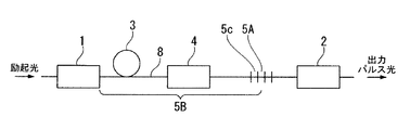
図1には、本発明の第1の実施形態のQスイッチ式ファイバレーザを示す。このQスイッチ式ファイバレーザは、自然放出光または誘導放出光を共振させるための共振器として、共振器用光ファイバ8に配置した高反射率構造1と低反射率構造2から成るファブリーペロー型共振器を有し、高反射率構造1と低反射率構造2との間に、希土類添加光ファイバ3と、部分的フィードバック光路5と、共振器内のエネルギーを十分に蓄えてから、瞬間的に光パルスを放出させるためのQスイッチ装置4とを設けている。また、部分的フィードバック光路5の分岐手段5Aとしては、光ファイバカプラ5aが配置され、伝搬距離延長手段5Bとしては光ファイバ5bが配置されている。光ファイバカプラ5aの入射導波路には、共振器用光ファイバ8と、伝搬距離延長手段5Bの機能を有する光ファイバ5bの片端が接続されており、光ファイバカプラ5aの出射導波路には、共振器用光ファイバ8と、伝搬距離延長手段5Bの機能を有する光ファイバ5bのもう一方の端が接続されており、出射導波路と接続されている光ファイバ5bの端は、光ファイバカプラ5aの入射導波路に通じる構造となっている。
なお、実際のQスイッチ式ファイバレーザにおいては、励起光源やQスイッチ装置に図示しないドライバ(駆動手段)が設けられるが、そのドライバ自体の構成は、従来と同様であればよい。
光ファイバカプラ5aおよび光ファイバ5bの挿入位置は、希土類添加光ファイバ3とQスイッチ装置4との間、あるいはQスイッチ装置4と低反射率構造2との間であれば、いずれでも良い。また、光ファイバカプラ5aおよび光ファイバ5bを、高反射率構造1と希土類添加光ファイバ3との間に挿入することもでき、その場合は分岐手段における励起光の透過率が100%に近いことが望ましい。
FIG. 1 shows a Q-switched fiber laser according to a first embodiment of the present invention. This Q-switched fiber laser is a Fabry-Perot resonator comprising a
In an actual Q-switch type fiber laser, a driver (driving means) (not shown) is provided in the excitation light source and the Q-switch device, but the configuration of the driver itself may be the same as that of the conventional one.
The insertion position of the
次に、図1に示した第1の実施形態のQスイッチ式ファイバレーザの動作および機能を説明する。Qスイッチ式ファイバレーザのファブリーペロー型共振器に入射した励起光は、共振器用光ファイバ8内を伝搬し、高反射率構造1を通り、Qスイッチ装置4により共振器のQ値は低く設定された状態で、希土類添加光ファイバ3に入射し、希土類添加光ファイバ3の希土類元素を励起する。希土類添加光ファイバの反転分布率が高くなった状態で、Qスイッチ装置4により共振器のQ値を高くすることにより、励起状態の希土類添加光ファイバ3で発生した自然放出光が、高反射率構造1または低反射率構造2により共振器内部へ反射され、その反射光が励起状態の希土類添加光ファイバ3へ入射することで誘導放出が発生し、光増幅され、部分的フィードバック光路5に入射する。部分的フィードバック光路5に入射した光パルスは、光ファイバカプラ5aにて、一定の光パワー比で光Aと光Bに分岐され、光Aは共振器用光ファイバ8を介して、Qスイッチ装置4を通り、低反射率構造2で反射される。一方、光Bは部分的フィードバック光路5の光ファイバ5bに入射し、伝搬することにより光ファイバ5b一周分の伝搬距離を延長され、再び光ファイバカプラ5aに戻る。光ファイバカプラ5aに戻された光Bは一定のパワー比で光Cと光Dに分岐され、光CはQスイッチ装置4に伝搬する。もう一方の光Dは再度、光ファイバ5bに入射し、光ファイバ5b一周分の伝搬距離を延長され、再び光ファイバカプラ5aに戻る。この部分的フィードバック動作が繰り返され、フィードバック回数に応じて光の伝搬距離が延長される。そして、共振器内での周回時間に応じた周期で発生する複数の小信号光パルスが出力光パルスに重ね合わされた結果、共振器用光ファイバ8を介して、低反射率構造2からパルス形状にうねりのない光パルスが出力される。
Next, the operation and function of the Q-switch type fiber laser of the first embodiment shown in FIG. 1 will be described. The excitation light incident on the Fabry-Perot resonator of the Q-switched fiber laser propagates through the resonator
なお図1の実施形態において、光ファイバカプラ5aにおける、光ファイバ5bへ分岐する光のパワー比率(光ファイバカプラ5aに入射する光のパワーに対する分岐光のパワー比率)は、60%±20%の範囲内であることが望ましい。前記パワー比率が60%±20%の範囲内であれば、Qスイッチ式ファイバレーザからの光パルスの形状が極めて滑らかになる。前記パワー比率が40%未満では、パルス形状のうねりが改善しない状態となり、80%を超えてもパルス形状のうねりが改善しない状態となる。
また、希土類添加光ファイバ3における反転分布率を高めることにより、光パルスの増幅が促進され、前記光パルスのパルスエネルギーが高まる。実施可能性から考えると、希土類元素の添加密度は2.0×1025〜4.0×1025[/m3]の範囲内とすることが望ましい。前記添加密度が低くなると、出力光パルスのパルスパワーが低下してしまう。
In the embodiment of FIG. 1, the power ratio of the light branched to the
Further, by increasing the population inversion ratio in the rare earth-doped
図2には、本発明の第2の実施形態のQスイッチ式ファイバレーザを示す。なお、図2において、図1に示したQスイッチ式ファイバレーザと同一の構成の部分については同一の符号を付し、その説明は省略し、以下の各図においても同様とする。
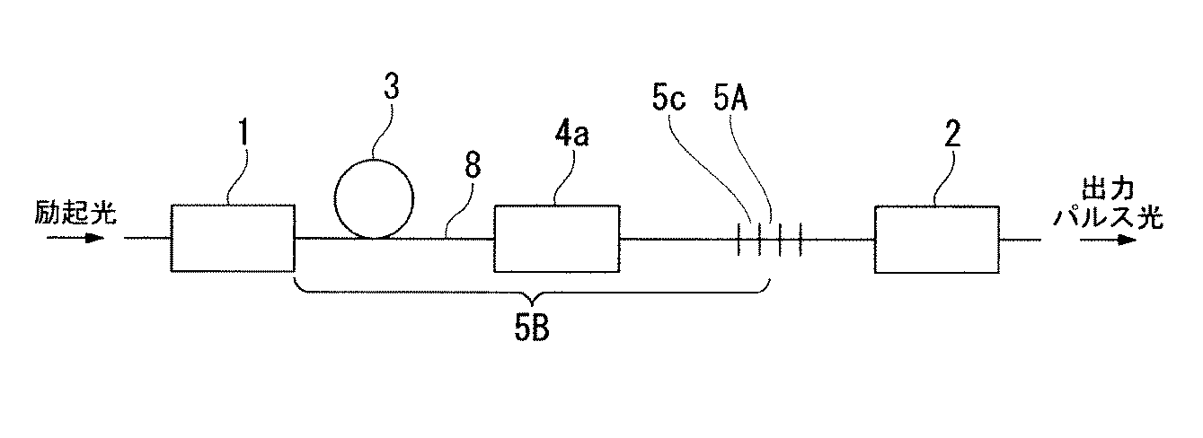
図2に示す第2の実施形態のQスイッチ式ファイバレーザにおいては、部分的フィードバック光路5の分岐手段5Aとしてファイバブラッググレーティング5cを設けており、ファイバブラッググレーティング5cで反射され、共振器内を伝搬して高反射率構造1で反射されて、再びファイバブラッググレーティング5cに入射するまで光の伝搬経路を、伝搬距離延長手段5Bとして機能させた構造となっている。なお、光ファイバブラッググレーティング5cの挿入位置は、Qスイッチ装置4と低反射率構造2との間でなければならない。
FIG. 2 shows a Q-switched fiber laser according to a second embodiment of the present invention. In FIG. 2, the same components as those of the Q-switch type fiber laser shown in FIG. 1 are denoted by the same reference numerals, description thereof is omitted, and the same applies to the following drawings.
In the Q-switched fiber laser of the second embodiment shown in FIG. 2, a fiber Bragg grating 5c is provided as a branching
次に、図2に示した第2の実施形態のQスイッチ式ファイバレーザにおける部分的フィードバック光路の動作および機能を説明する。部分的フィードバック光路5に入射した光は、ファイバブラッググレーティング5cの反射率に応じて、光Eと光Fに分岐され、光Eはファイバブラッググレーティング5cを透過し、低反射率構造2で反射される。光Fはファイバブラッググレーティング5cで反射され、共振器用光ファイバ8中を伝搬し、Qスイッチ装置4および希土類添加光ファイバ3を通って高反射率構造1で反射され、再び希土類添加光ファイバ3に入射する。そして、光Fは希土類添加光ファイバ3で誘導放出光を発生させ、Qスイッチ装置4を通り、ファイバブラッググレーティング5cに再び入射する。したがって、図2の実施形態の部分的フィードバック光路5における伝搬距離延長手段5Bは、高反射率構造1の出射端面から、共振器用光ファイバ8を介して希土類添加光ファイバ3およびQスイッチ装置を通り、ファイバブラッググレーティング5cで反射される位置までの光の伝搬経路となり、延長される伝搬距離は前記伝搬経路の往復距離となる。部分的フィードバック光路5としての前述の動作により、フィードバック回数に応じて光の伝搬距離が延長される。そして、共振器内での周回時間に応じた周期で発生する複数の小信号光パルスが出力光パルスに重ね合わされた結果、共振器用光ファイバ8を介して、低反射率構造2からパルス形状にうねりのない光パルスが出力される。
Next, the operation and function of the partial feedback optical path in the Q-switched fiber laser of the second embodiment shown in FIG. 2 will be described. The light incident on the partial feedback
なお図2の実施形態において、ファイバブラッググレーティング5cの反射率(ファイバブラッググレーティング5cに入射する光のパワーに対する、ファイバブラッググレーティング5cで反射する光のパワーの比率)は、1%〜10%の範囲内であることが望ましい。前記反射率が1%〜10%の範囲内であれば、Qスイッチ式ファイバレーザからの光パルスの形状のうねりがなくなる。前記反射率が1%未満では、フィードバックの回数が少ないため、パルス形状のうねりが改善されない結果となり、一方10%を超えれば共振器出力パワーが低くなることによりパルスエネルギーの低下が生じることがある。 In the embodiment of FIG. 2, the reflectance of the fiber Bragg grating 5c (ratio of the power of light reflected by the fiber Bragg grating 5c to the power of light incident on the fiber Bragg grating 5c) is in the range of 1% to 10%. It is desirable to be within. If the reflectance is in the range of 1% to 10%, the undulation of the shape of the light pulse from the Q-switch type fiber laser is eliminated. If the reflectance is less than 1%, the number of feedbacks is small, so that the undulation of the pulse shape is not improved. On the other hand, if it exceeds 10%, the resonator output power may be lowered, resulting in a decrease in pulse energy. .
図3には、本発明の第3の実施形態のQスイッチ式ファイバレーザを示す。
図3に示す第3の実施形態のQスイッチ式ファイバレーザは、Qスイッチ装置4として音響光学素子4aを配置した構成となっている。
FIG. 3 shows a Q-switched fiber laser according to a third embodiment of the present invention.
The Q-switch type fiber laser of the third embodiment shown in FIG. 3 has a configuration in which an
図3において、音響光学素子4aの材料にあった高周波信号の振幅を変化させることによって、音響光学素子4aの回折効率が変化し、音響光学素子4aが含まれるモジュールの損失が変化する。音響光学素子4aに入射した光パルスのパワーは、前記モジュールの損失の制御状態に応じて変化し、出射する。音響光学素子4aにより共振器損失が高い状態になっているときに、希土類添加光ファイバ3が励起され、反転分布率が所定のレベルよりも高くなったときに、音響光学素子4aにより共振器損失を低くすることで、パルスパワーが高い光パルスが出射される。
In FIG. 3, the diffraction efficiency of the
図4には、図3に示す第3の実施形態のQスイッチ式ファイバレーザにおいて、部分的フィードバック光路5の分岐手段5Aとしてファイバブラッググレーティング5cを設け、ファイバブラッググレーティング5cで反射され、前記共振器内を伝搬し高反射率構造1で反射されて、再びファイバブラッググレーティングに入射するまで光の伝搬経路を、伝搬距離延長手段5Bとして機能させた、本発明の第3の実施形態のQスイッチ式ファイバレーザを示す。なお、ファイバブラッググレーティング5cの挿入位置は、図4に示すように音響光学素子4aと低反射率構造2との間でなければならない。
In FIG. 4, in the Q-switched fiber laser of the third embodiment shown in FIG. 3, a fiber Bragg grating 5 c is provided as a branching
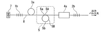
図5には、本発明の第4の実施形態のQスイッチ式ファイバレーザを示す。このQスイッチ式ファイバレーザは自然放出光または誘導放出光を共振させるための共振器として、共振器用光ファイバ8に配置した励起カプラ1aと出力カプラ2aから成るリング型共振器を有し、励起カプラ1aに近い側から希土類添加光ファイバ3と、バンドパスフィルタ6と、Qスイッチ装置4と、分岐手段5Aとしての光ファイバカプラ5aおよび伝搬距離延長手段5Bとしての光ファイバ5bを有する部分的フィードバック光路5とを配置した構成になっている。
FIG. 5 shows a Q-switched fiber laser according to a fourth embodiment of the present invention. This Q-switch type fiber laser has a ring type resonator composed of a
なお、この部分的フィードバック光路5の挿入位置は、希土類添加光ファイバ3とバンドパスフィルタ6との間、またはバンドパスフィルタ6とQスイッチ装置4との間か、またはQスイッチ装置4と出力カプラ2aとの間、あるいは出力カプラ2aと励起カプラ1aとの間であれば、いずれでも良い。
この実施形態において、バンドパスフィルタ6とQスイッチ装置4の配置を入れ替えても、本発明の効果が得られ、Qスイッチ装置4と出力カプラ2aの配置を入れ替えても、本発明の効果が得られる。
The insertion position of the partial feedback
In this embodiment, the effect of the present invention can be obtained even if the arrangement of the bandpass filter 6 and the
次に、図5に示した第4の実施形態のQスイッチ式ファイバレーザの動作および機能を説明する。このリング型共振器に入射した励起光は、励起カプラ1aを通り、希土類添加光ファイバ3に入射し、希土類元素を励起する。励起状態の希土類添加光ファイバ3で発生した光は、バンドパスフィルタ6およびQスイッチ装置4を通り、部分的フィードバック光路5に入射する。入射した光は、部分的フィードバック光路5の分岐手段5Aである光ファイバカプラ5aにて一定の光パワー比で光Aと光Bに分岐され、光Aは出力カプラ2aに伝搬する。一方、光Bは伝搬距離延長手段5Bである光ファイバ5bに入射し、一定の光路長を伝搬することにより、伝搬距離を延長され、再び光ファイバカプラ5aに戻る。光ファイバカプラ5aに戻された光Bは一定の光パワー比で光Cと光Dに分岐され、光Cは出力カプラ2aに伝搬し、もう一方の光パルスDは再度、光ファイバ5bに入射し、一定の光路長を伝搬することにより、伝搬距離を延長され、再び光ファイバカプラ5aに戻る。また、出力カプラ2aに入射した光パルスは一定の光パワー比で分岐され、一方の光パルスは共振器からの出力光パルスとして出射し、もう一方の光パルスは再び励起カプラ1aを通り、希土類添加光ファイバ3に入射する。このとき、希土類添加光ファイバ3内で誘導放出光が発生し、誘導放出光がリング状の共振器用光ファイバ8内を励振する。共振器用光ファイバ8を伝搬する光が再び励起状態の希土類添加光ファイバ3へ入射することで光パルスが発生し、共振器内での周回時間に応じた周期で発生する複数の小信号光パルスが出力光パルスに重ね合わされた結果、パルス形状にうねりのない光パルスが出力される。
Next, the operation and function of the Q-switch type fiber laser of the fourth embodiment shown in FIG. 5 will be described. The pumping light incident on this ring resonator passes through the pumping
実施例1
この実施例1で使用したQスイッチ式ファイバレーザの全体構成を図6に示す。このQスイッチ式ファイバレーザは、第1の実施形態のQスイッチ式ファイバレーザの構成に基づき、高反射率構造1としての高反射ファイバブラッググレーティング1bと、低反射率構造2としての低反射ファイバブラッググレーティング2bと、希土類添加光ファイバ3としてのYb添加光ファイバ3aと、Qスイッチ装置4としての音響光学素子4aと、部分的フィードバック光路5の分岐手段5Aとしての光ファイバカプラ5aと、部分的フィードバック光路5の伝搬距離延長手段5Bとしての光ファイバ5bとを同一の共振器用光ファイバ8上に配置し、励起光用光源として半導体レーザ7を設けたものである。なお、半導体レーザ7および音響光学素子4aは図示しないドライバを装備している。
Example 1
The overall configuration of the Q-switched fiber laser used in Example 1 is shown in FIG. This Q-switched fiber laser is based on the configuration of the Q-switched fiber laser according to the first embodiment. The high-reflection fiber Bragg grating 1b as the high-
図6に示すQスイッチ式ファイバレーザにおいては、半導体レーザ7から出射した励起光は、高反射ファイバブラッググレーティング1bを通り、音響光学素子4aでQ値を低く設定した状態で、Yb添加光ファイバ3aに入射し、Yb元素を励起する。これにより、Yb添加光ファイバ3aの反転分布が高くなり、この状態で音響光学素子4aにより共振器のQ値を高くすると、Yb添加光ファイバ3aで発生した自然放出光が、高反射ファイバブラッググレーティング1bと低反射ファイバブラッググレーティング2bにより、共振器内に反射される。前記反射光が励起状態のYb添加光ファイバ3aへ入射することで誘導放出光が発生し、前記誘導放出光が高反射ファイバブラッググレーティング1bと低反射ファイバブラッググレーティング2bにより、共振器内に反射される。前記反射光が再び励起状態のYb添加光ファイバ3aへ入射することで、光パルスが発生する。光パルスの発生途中で部分的フィードバック光路5に入射した光は、部分的フィードバック光路5の光ファイバカプラ5aにて一定の光パワー比で光Aと光Bに分岐され、光Aは音響光学素子4aに伝搬する。一方、光Bは部分的フィードバック光路5の光ファイバ5bに伝搬し、一定の光路長を伝搬することにより、伝搬距離を延長され、再び光ファイバカプラ5aに戻る。光ファイバカプラ5aに戻された光Bは一定の光パワー比で光Cと光Dに分岐され、光Cは音響光学素子4aに伝搬する。もう一方の光Dは再度、光ファイバ5bに伝搬され、一定の光路長を伝搬することにより、伝搬距離を延長され、再び光ファイバカプラ5aに戻る。この部分的フィードバック動作が繰り返され、フィードバック回数に応じて光の伝搬距離が延長される。前述のQスイッチ式ファイバレーザの動作により、共振器内での周回時間に応じた周期で発生する複数の小信号光パルスが出力光パルスに重ね合わされた結果、低反射ファイバブラッググレーティング2bから、パルス形状にうねりのない光パルスが出力される。
In the Q-switched fiber laser shown in FIG. 6, the pumping light emitted from the
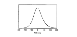
図6に示すQスイッチ式ファイバレーザにおいて、表1に示す光学特性の光部品を配置して構成したときに得られた出力光パルスを図7に示す。 FIG. 7 shows output light pulses obtained when the optical components having the optical characteristics shown in Table 1 are arranged in the Q-switched fiber laser shown in FIG.
以上のように実施例1の部分的フィードバック光路を設けたQスイッチ式ファイバレーザによれば、パルスパワーが高く、パルス幅が100ns〜500nsであり、かつ小信号パルスやうねりのない滑らかなパルス形状を有する光パルスが生成されることが確認された。 As described above, according to the Q-switch type fiber laser provided with the partial feedback optical path of the first embodiment, the pulse power is high, the pulse width is 100 ns to 500 ns, and the smooth pulse shape has no small signal pulse or undulation. It was confirmed that an optical pulse having
実施例2
実施例1と同様の構成のQスイッチ式ファイバレーザにおいて、部分的フィードバック光路5の光ファイバカプラ5aにおいて、伝搬距離延長手段5Bである光ファイバ5bに分岐される光パワーを、部分的フィードバック光路5に入射する光パルスの30%、70%、90%と変化させたときの、出力光パルス波形を図8に示す。また、共振器用光ファイバ8に側圧を加えたときの出力光パルスのパルス幅の変動、および平均パワーの変動の測定結果を表2に示す。
Example 2
In the Q-switched fiber laser having the same configuration as that of the first embodiment, the optical power branched to the
以上の実施例2に示すように、Qスイッチ式ファイバレーザの部分的フィードバック光路における部分的フィードバック光路への入射光に対する伝搬距離延長手段への光のパワー分岐量を70%とすることにより、出力光パルスのパルス幅のうねり、および平均パワーの側圧に対する変動を著しく小さくし得ることが確認された。 As shown in the second embodiment, the power branching amount of the light to the propagation distance extending means for the incident light to the partial feedback optical path in the partial feedback optical path of the Q-switched fiber laser is set to 70%, thereby outputting It was confirmed that the fluctuation of the pulse width of the light pulse and the fluctuation of the average power with respect to the side pressure can be remarkably reduced.
実施例3
実施例1と同様の構成のQスイッチ式ファイバレーザにおいて、部分的フィードバック光路5の光ファイバカプラ5aにおいて、伝搬距離延長手段5Bである光ファイバ5bに分岐される光パワーを部分的フィードバック光路5に入射する光パルスの70%に固定し、光ファイバ5bの長さ(フィードバック長)を1000mm、2000mm、3000mmと変化させたときの、出力光パルス波形を図9に示す。Qスイッチ式ファイバレーザの部分的フィードバック光路の光ファイバ5bの長さを1000mm、2000mm、3000mmと変化させたときのいずれの出力光パルス波形においても、中心のパワーのピークが崩れることなく、大きなうねりも発生していない。
さらに、共振器用光ファイバ8に側圧を加えたときの出力光パルスのパルス幅の変動、および平均パワーの変動の測定結果を表3に示す。出力光パルスの平均パワーの変動は、Qスイッチ式ファイバレーザの共振器長2000mmに対して、部分的フィードバック光路の光ファイバ5bの長さを1000mmとしたときに著しく低くなっている。
Example 3
In the Q-switched fiber laser having the same configuration as that of the first embodiment, in the
Further, Table 3 shows the measurement results of the fluctuation of the pulse width of the output light pulse and the fluctuation of the average power when the lateral pressure is applied to the resonator
以上の実施例3に示すように、Qスイッチ式ファイバレーザの部分的フィードバック光路において、伝搬距離延長手段5Bである光ファイバ5bに分岐される光パワーが部分的フィードバック光路5に入射する光パルスの70%である場合には、フィードバック長によらず、うねりのない出力光パルスが得られた。特に、共振器長2000mmに対して部分的フィードバック光路のフィードバック長を1000mmとすることにより、出力光パルス形状を極めて滑らかにし、出力光パルスの平均パワーの側圧に対する変動を著しく小さくし得ることが確認された。なお、共振器長2000mmに対して部分的フィードバック光路のフィードバック長は500mm〜1500mmの範囲内が好適であることが確認されているが、共振器長が異なる場合には、フィードバック長はその共振器長に応じて適切に選択する必要がある。
As shown in Example 3 above, in the partial feedback optical path of the Q-switch type fiber laser, the optical power branched to the
実施例4
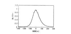
実施例4で使用したQスイッチ式ファイバレーザは、第2の実施形態のQスイッチ式ファイバレーザの構成に基づき、部分的フィードバック光路の分岐手段として反射率4%のファイバブラッググレーティングを設け、ファイバブラッググレーティング5cで反射され、共振器内を伝搬して高反射率構造1で反射されて、再びファイバブラッググレーティング5cに入射するまで光の伝搬経路を、伝搬距離延長手段5Bとして機能させたものである。このQスイッチ式ファイバレーザから得られた出力光パルス波形を図10に示す。
Example 4
The Q-switched fiber laser used in Example 4 is based on the configuration of the Q-switched fiber laser of the second embodiment, and a fiber Bragg grating having a reflectance of 4% is provided as a branching means for a partial feedback optical path. The light propagation path is made to function as the propagation
図10に示すように、実施例4の場合も出力光パルス形状のうねりがなくなることが確認された。 As shown in FIG. 10, it was confirmed that the undulation of the output light pulse shape was eliminated also in the case of Example 4.
1 高反射率構造
1a 励起カプラ
1b 高反射ファイバブラッググレーティング
2 低反射率構造
2a 出力カプラ
2b 低反射ファイバブラッググレーティング
3 希土類添加光ファイバ
3a Yb添加光ファイバ
4 Qスイッチ装置
4a 音響光学素子
5 部分的フィードバック光路
5A 分岐手段
5B 伝搬距離延長手段
5a 光ファイバカプラ
5b 光ファイバ
5c ファイバブラッググレーティング
6 バンドパスフィルタ
7 半導体レーザ
8 共振器用光ファイバ
DESCRIPTION OF
Claims (8)
分岐手段と伝搬距離延長手段とを有する部分的フィードバック光路が前記共振器内に設けられており、前記分岐手段は前記部分的フィードバック光路に入射した光を一定の光パワー比で、共振器用光ファイバに出射する光と、前記伝搬距離延長手段に出射する光とに分離するように構成され、また前記伝搬距離延長手段は、入射してきた光を一定の光路長内で伝搬させることにより前記光の伝搬距離を延長して、再び前記分岐手段に入射させるように構成されていることを特徴とするQスイッチ式ファイバレーザ。 In a Q-switched fiber laser comprising a rare-earth-doped optical fiber for optical pulse amplification and a Q-switch device, and having a resonator for resonating spontaneous emission light or stimulated emission light,
A partial feedback optical path having a branching means and a propagation distance extending means is provided in the resonator, and the branching means has a constant optical power ratio of light incident on the partial feedback optical path, and an optical fiber for the resonator. And the propagation distance extending means propagates the incident light within a certain optical path length by propagating the incident light within a certain optical path length. A Q-switched fiber laser characterized in that the propagation distance is extended and the light is again incident on the branching means.
前記部分的フィードバック光路の分岐手段および伝搬距離延長手段として、それぞれ光ファイバカプラおよび光ファイバを設け、前記光ファイバの両端が前記光ファイバカプラの入射導波路と出射導波路に接続されていることを特徴とするQスイッチ式ファイバレーザ。 The Q-switched fiber laser according to claim 1,
An optical fiber coupler and an optical fiber are provided as branching means and propagation distance extending means of the partial feedback optical path, respectively, and both ends of the optical fiber are connected to the incident waveguide and the outgoing waveguide of the optical fiber coupler. Characteristic Q-switch type fiber laser.
前記光ファイバカプラから前記光ファイバに分岐される光のパワー比率が60%±20%の範囲内にあるように構成したことを特徴とするQスイッチ式ファイバレーザ。 The Q-switched fiber laser according to claim 2,
A Q-switch type fiber laser characterized in that a power ratio of light branched from the optical fiber coupler to the optical fiber is in a range of 60% ± 20%.
前記部分的フィードバック光路の分岐手段として、ファイバブラッググレーティングを設け、ファイバブラッググレーティングで反射され、前記共振器内を伝搬し、再びファイバブラッググレーティングに入射するまで光の伝搬経路を、伝搬距離延長手段として機能させることを特徴とする光Qスイッチ式ファイバレーザ。 The Q-switched fiber laser according to claim 1,
As a means for branching the partial feedback optical path, a fiber Bragg grating is provided, reflected by the fiber Bragg grating, propagates in the resonator, and is used as a propagation distance extending means until it enters the fiber Bragg grating again. An optical Q-switch type fiber laser characterized by functioning.
前記ファイバブラッググレーティングの反射率が1%〜10%の範囲内にあるように構成したことを特徴とするQスイッチ式ファイバレーザ。 The Q-switched fiber laser according to claim 4,
A Q-switch type fiber laser characterized in that the reflectance of the fiber Bragg grating is in the range of 1% to 10%.
前記Qスイッチ装置として、音響光学素子を設けたことを特徴とするQスイッチ式ファイバレーザ。 In the Q-switch type fiber laser according to any one of claims 1 to 5,
A Q-switch type fiber laser comprising an acousto-optic device as the Q-switch device.
前記共振器として、ファブリーペロー型共振器を設けたことを特徴とするQスイッチ式ファイバレーザ。 In the Q-switch type fiber laser according to any one of claims 1 to 6,
A Q-switch type fiber laser comprising a Fabry-Perot resonator as the resonator.
前記共振器として、リング型共振器を設けたことを特徴とするQスイッチ式ファイバレーザ。 In the Q-switch type fiber laser according to any one of claims 1 to 3,
A Q-switch type fiber laser comprising a ring-type resonator as the resonator.
Priority Applications (2)
| Application Number | Priority Date | Filing Date | Title |
|---|---|---|---|
| JP2011024833A JP2012164860A (en) | 2011-02-08 | 2011-02-08 | Q switch type fiber laser |
| PCT/JP2012/051210 WO2012108248A1 (en) | 2011-02-08 | 2012-01-20 | Q-switched fiber laser |
Applications Claiming Priority (1)
| Application Number | Priority Date | Filing Date | Title |
|---|---|---|---|
| JP2011024833A JP2012164860A (en) | 2011-02-08 | 2011-02-08 | Q switch type fiber laser |
Publications (1)
| Publication Number | Publication Date |
|---|---|
| JP2012164860A true JP2012164860A (en) | 2012-08-30 |
Family
ID=46638466
Family Applications (1)
| Application Number | Title | Priority Date | Filing Date |
|---|---|---|---|
| JP2011024833A Pending JP2012164860A (en) | 2011-02-08 | 2011-02-08 | Q switch type fiber laser |
Country Status (2)
| Country | Link |
|---|---|
| JP (1) | JP2012164860A (en) |
| WO (1) | WO2012108248A1 (en) |
Cited By (2)
| Publication number | Priority date | Publication date | Assignee | Title |
|---|---|---|---|---|
| CN104134927A (en) * | 2014-07-25 | 2014-11-05 | 上海交通大学 | Nonlinear effect Q-switched fiber laser |
| WO2018074511A1 (en) | 2016-10-21 | 2018-04-26 | 株式会社フジクラ | Fiber laser device |
Families Citing this family (1)
| Publication number | Priority date | Publication date | Assignee | Title |
|---|---|---|---|---|
| CN103199418A (en) * | 2013-04-11 | 2013-07-10 | 杭州镭克普光电技术有限公司 | Periodical domain reversal crystal electro-optic Q-switched-based pulse optical fiber laser |
Citations (6)
| Publication number | Priority date | Publication date | Assignee | Title |
|---|---|---|---|---|
| JPH02260479A (en) * | 1989-03-30 | 1990-10-23 | Toshiba Corp | Laser oscillator |
| JPH04287384A (en) * | 1990-11-20 | 1992-10-12 | General Instr Corp | Longitudinal mode selection laser |
| JPH06291395A (en) * | 1993-03-30 | 1994-10-18 | Ando Electric Co Ltd | Optical fiber ring laser capable of changing wavelength |
| JP2004356485A (en) * | 2003-05-30 | 2004-12-16 | Ishikawajima Harima Heavy Ind Co Ltd | Resonator |
| JP2005500705A (en) * | 2001-08-21 | 2005-01-06 | ジェンドロン、デニス、ジェイ. | Suppression of mode beat noise in Q-switched pulse laser using new Q-switch device |
| JP2008235340A (en) * | 2007-03-16 | 2008-10-02 | Fujikura Ltd | Optical pulse generator and optical fiber laser device |
-
2011
- 2011-02-08 JP JP2011024833A patent/JP2012164860A/en active Pending
-
2012
- 2012-01-20 WO PCT/JP2012/051210 patent/WO2012108248A1/en active Application Filing
Patent Citations (6)
| Publication number | Priority date | Publication date | Assignee | Title |
|---|---|---|---|---|
| JPH02260479A (en) * | 1989-03-30 | 1990-10-23 | Toshiba Corp | Laser oscillator |
| JPH04287384A (en) * | 1990-11-20 | 1992-10-12 | General Instr Corp | Longitudinal mode selection laser |
| JPH06291395A (en) * | 1993-03-30 | 1994-10-18 | Ando Electric Co Ltd | Optical fiber ring laser capable of changing wavelength |
| JP2005500705A (en) * | 2001-08-21 | 2005-01-06 | ジェンドロン、デニス、ジェイ. | Suppression of mode beat noise in Q-switched pulse laser using new Q-switch device |
| JP2004356485A (en) * | 2003-05-30 | 2004-12-16 | Ishikawajima Harima Heavy Ind Co Ltd | Resonator |
| JP2008235340A (en) * | 2007-03-16 | 2008-10-02 | Fujikura Ltd | Optical pulse generator and optical fiber laser device |
Cited By (4)
| Publication number | Priority date | Publication date | Assignee | Title |
|---|---|---|---|---|
| CN104134927A (en) * | 2014-07-25 | 2014-11-05 | 上海交通大学 | Nonlinear effect Q-switched fiber laser |
| WO2018074511A1 (en) | 2016-10-21 | 2018-04-26 | 株式会社フジクラ | Fiber laser device |
| EP3531513A4 (en) * | 2016-10-21 | 2020-06-03 | Fujikura Ltd. | Fiber laser device |
| US11070021B2 (en) | 2016-10-21 | 2021-07-20 | Fujikura Ltd. | Fiber laser device |
Also Published As
| Publication number | Publication date |
|---|---|
| WO2012108248A1 (en) | 2012-08-16 |
Similar Documents
| Publication | Publication Date | Title |
|---|---|---|
| JP2017126088A (en) | Cascaded Raman fiber laser system based on filter fiber | |
| JP2006005349A (en) | Pulse laser equipment and method therefor | |
| EP2154759A1 (en) | Fiber laser | |
| JP5822850B2 (en) | Laser equipment | |
| JP2017045075A (en) | Cascaded raman lasing system | |
| US20120069860A1 (en) | Gain-Switched Fiber Laser | |
| WO2011109753A1 (en) | Wavelength beam combining based pump / pulsed lasers | |
| JP6456250B2 (en) | Laser apparatus and laser processing machine | |
| CN111373614B (en) | Device for providing optical radiation | |
| JP4708109B2 (en) | Fiber laser equipment | |
| JP5013407B2 (en) | Laser oscillator | |
| US9647410B2 (en) | Multimode Fabry-Perot fiber laser | |
| JP2011204834A (en) | Fiber laser light source and wavelength conversion laser device using the same | |
| JP2012164860A (en) | Q switch type fiber laser | |
| JP2009537979A (en) | High-power optical fiber pulse laser equipment | |
| JP2012156175A (en) | Fiber laser light source device and wavelength conversion laser light source device using the same | |
| CN113708204B (en) | Multi-cavity composite pulse laser and multi-cavity composite pulse laser amplifier | |
| EP3309912B1 (en) | Laser light-source apparatus and laser pulse light generating method | |
| JP4897960B2 (en) | Pulse laser equipment | |
| JP2012129423A (en) | Fiber laser and continuous light oscillation method for fiber laser | |
| JP6093511B2 (en) | Pulse fiber laser device and pulse light output control method | |
| JP5379844B2 (en) | Laser oscillator | |
| Liao et al. | Modified oscillating-amplifying integrated fiber laser for stimulated Raman scattering suppression | |
| Guan et al. | Suppression of self-pulsations in dual-clad, ytterbium-doped fiber lasers | |
| DK2443705T3 (en) | SYSTEM FOR EMISSIONS OF polychromatic LIGHT WITH COMPENSATED SUBKAVITETER |
Legal Events
| Date | Code | Title | Description |
|---|---|---|---|
| A131 | Notification of reasons for refusal |
Free format text: JAPANESE INTERMEDIATE CODE: A131 Effective date: 20121204 |
|
| A521 | Written amendment |
Free format text: JAPANESE INTERMEDIATE CODE: A523 Effective date: 20130204 |
|
| A02 | Decision of refusal |
Free format text: JAPANESE INTERMEDIATE CODE: A02 Effective date: 20130305 |