JP2012164609A - Electrode containing layered metal oxide, and fuel cell comprising solid electrolyte layer - Google Patents
Electrode containing layered metal oxide, and fuel cell comprising solid electrolyte layer Download PDFInfo
- Publication number
- JP2012164609A JP2012164609A JP2011026121A JP2011026121A JP2012164609A JP 2012164609 A JP2012164609 A JP 2012164609A JP 2011026121 A JP2011026121 A JP 2011026121A JP 2011026121 A JP2011026121 A JP 2011026121A JP 2012164609 A JP2012164609 A JP 2012164609A
- Authority
- JP
- Japan
- Prior art keywords
- fuel cell
- layered metal
- metal oxide
- electrode
- solid electrolyte
- Prior art date
- Legal status (The legal status is an assumption and is not a legal conclusion. Google has not performed a legal analysis and makes no representation as to the accuracy of the status listed.)
- Granted
Links
Images


Classifications
-
- Y—GENERAL TAGGING OF NEW TECHNOLOGICAL DEVELOPMENTS; GENERAL TAGGING OF CROSS-SECTIONAL TECHNOLOGIES SPANNING OVER SEVERAL SECTIONS OF THE IPC; TECHNICAL SUBJECTS COVERED BY FORMER USPC CROSS-REFERENCE ART COLLECTIONS [XRACs] AND DIGESTS
- Y02—TECHNOLOGIES OR APPLICATIONS FOR MITIGATION OR ADAPTATION AGAINST CLIMATE CHANGE
- Y02E—REDUCTION OF GREENHOUSE GAS [GHG] EMISSIONS, RELATED TO ENERGY GENERATION, TRANSMISSION OR DISTRIBUTION
- Y02E60/00—Enabling technologies; Technologies with a potential or indirect contribution to GHG emissions mitigation
- Y02E60/30—Hydrogen technology
- Y02E60/50—Fuel cells
Landscapes
- Catalysts (AREA)
- Conductive Materials (AREA)
- Inert Electrodes (AREA)
- Fuel Cell (AREA)
- Inorganic Compounds Of Heavy Metals (AREA)
Abstract
【課題】高い起電力及び十分な電流密度を得ることができる層状金属酸化物を含む電極を備える燃料電池を提供すること。
【解決手段】電極触媒と、第1の層状金属酸化物と、を含み、電極触媒100重量部に対して、第1の層状酸化物が50〜150重量部である、アノード電極と、カーボン材料と、第2の層状金属酸化物と、を含み、カーボン材料100重量部に対して、第2の層状酸化物が150〜250重量部である、カソード電極と、アノード電極とカソード電極との間に配置され、第3の層状金属酸化物を含む固体電解質層と、を備え、第1及び第3の層状金属酸化物は水蒸気処理が施されたものである、燃料電池。
【選択図】図1A fuel cell including an electrode including a layered metal oxide capable of obtaining a high electromotive force and a sufficient current density is provided.
An anode electrode comprising: an electrode catalyst; and a first layered metal oxide, wherein the first layered oxide is 50 to 150 parts by weight with respect to 100 parts by weight of the electrode catalyst; and a carbon material And between the cathode electrode and the anode electrode and the cathode electrode, wherein the second layered oxide is 150 to 250 parts by weight with respect to 100 parts by weight of the carbon material. And a solid electrolyte layer containing a third layered metal oxide, wherein the first and third layered metal oxides are subjected to steam treatment.
[Selection] Figure 1
Description
本発明は、層状金属酸化物を含む電極及び固体電解質層を備える燃料電池に関する。 The present invention relates to a fuel cell including an electrode including a layered metal oxide and a solid electrolyte layer.
下記特許文献1には、固体電解質や電極材料として、NaCo2O4やLaFe3Sr3O10、Bi4Sr14Fe24O56という層状金属酸化物を用いた燃料電池に関する発明が記載されている。当該燃料電池は、燃料としてヒドラジン(N2H4)や触媒として白金を使用せず、室温程度の低温条件下(20〜80℃程度)であっても高い起電力が得ることができることを特徴としている。
上記特許文献1のとおり、固体電解質や電極材料として層状金属酸化物を用いた燃料電池は、高い起電力を得られたが、電流密度についてはより向上させる余地が見られた。
As described in
本発明は上記課題に鑑みてなされたものであり、高い起電力及び十分な電流密度を得ることができる層状金属酸化物を含む電極及び固体電解質層を備える燃料電池を提供することを目的とする。 The present invention has been made in view of the above problems, and an object thereof is to provide a fuel cell including an electrode including a layered metal oxide and a solid electrolyte layer capable of obtaining a high electromotive force and a sufficient current density. .
上記目的を達成するため、本発明は、電極触媒と、第1の層状金属酸化物と、を含み、電極触媒100重量部に対して、第1の層状酸化物が50〜150重量部である、アノード電極と、カーボン材料と、第2の層状金属酸化物と、を含み、カーボン材料100重量部に対して、第2の層状酸化物が150〜250重量部である、カソード電極と、アノード電極とカソード電極との間に配置され、第3の層状金属酸化物を含む固体電解質層と、を備え、第1及び第3の層状金属酸化物は水蒸気処理が施されたものである、燃料電池を提供する。 In order to achieve the above object, the present invention includes an electrode catalyst and a first layered metal oxide, wherein the first layered oxide is 50 to 150 parts by weight with respect to 100 parts by weight of the electrode catalyst. A cathode electrode comprising: an anode electrode; a carbon material; and a second layered metal oxide, wherein the second layered oxide is 150 to 250 parts by weight with respect to 100 parts by weight of the carbon material. A solid electrolyte layer including a third layered metal oxide disposed between the electrode and the cathode electrode, wherein the first and third layered metal oxides have been subjected to steam treatment. Provide batteries.
本発明者らは、層状金属酸化物を固体電解質層や電極材料として用いた燃料電池について鋭意検討したところ、アノード電極及びカソード電極が特定の比率で電極触媒又はカーボン材料と層状金属酸化物を含有し、かつ、固体電解質層及びアノード電極として、これらに含まれる層状金属酸化物に水蒸気処理が施されたものを備えることによって、高い起電力及び十分な電力密度を得ることができることを見出した。 The present inventors diligently studied a fuel cell using a layered metal oxide as a solid electrolyte layer or an electrode material, and the anode electrode and the cathode electrode contained an electrode catalyst or a carbon material and the layered metal oxide in a specific ratio. In addition, it has been found that a high electromotive force and a sufficient power density can be obtained by providing a solid electrolyte layer and an anode electrode in which a layered metal oxide contained therein is subjected to a steam treatment.
上記本発明の燃料電池においては、固体電解質層に含まれる第3の層状金属酸化物と、アノード電極に含まれる第1の層状酸化物とが水蒸気処理を施されることによって、層状金属酸化物中の酸素欠陥に水分子が水和し、水酸化物イオンの伝導性が発現することから、高い起電力及び十分な電流密度を得ることが可能となると考えられる。加えて、アノード電極及びカソード電極として、層状酸化物をそれぞれ特定の割合で含むものを備えることで、各電極はさらに優れた伝導性を発現することができ、その結果、一層高い起電力及び電流密度が得られるようになる。 In the fuel cell of the present invention, the third layered metal oxide contained in the solid electrolyte layer and the first layered oxide contained in the anode electrode are subjected to water vapor treatment, whereby the layered metal oxide is formed. It is considered that a high electromotive force and a sufficient current density can be obtained because water molecules are hydrated by oxygen vacancies therein and the conductivity of hydroxide ions is exhibited. In addition, by providing an anode electrode and a cathode electrode each containing a layered oxide at a specific ratio, each electrode can exhibit further excellent conductivity, and as a result, higher electromotive force and current can be obtained. Density comes to be obtained.
本発明において、電極触媒は、Fe、Co及びNiを含む合金部分と、当該合金部分を形成していないFe部分と、を含む合金材料を有することが好ましい。アノード電極における電極触媒が、Fe、Co及びNiを含む合金部分と、当該合金部分を形成していないFe部分と、を含む合金材料を有する電極触媒であることによって、燃料電池に用いられた場合に高い起電力及び十分な電流密度を得ることができる。 In the present invention, the electrode catalyst preferably has an alloy material including an alloy part containing Fe, Co, and Ni and an Fe part not forming the alloy part. When the electrode catalyst in the anode electrode is an electrode catalyst having an alloy material containing an alloy part containing Fe, Co and Ni and an Fe part not forming the alloy part, and used in a fuel cell In addition, a high electromotive force and a sufficient current density can be obtained.
また、本発明において第1、第2及び第3の層状金属酸化物は、それぞれ同一であっても異なっていてもよく、下記一般式(1)で表される層状金属酸化物、又は、NaCo2O4であることが好ましい。
(La1−xAx)(Sr1−yBy)3(Co1−zCz)3O10−δ (1)
[式中、AはLa以外の希土類元素であり、BはMg、Ca又はBaであり、CはTi、V、Cr又はMnであり、0≦x<1、0≦y<1、0≦z<1、δは酸素欠損量である。]
In the present invention, the first, second and third layered metal oxides may be the same or different from each other, and the layered metal oxide represented by the following general formula (1) or NaCo 2 O 4 is preferred.
(La 1-x A x) (Sr 1-y B y) 3 (Co 1-z C z) 3 O 10-δ (1)
[In the formula, A is a rare earth element other than La, B is Mg, Ca, or Ba, C is Ti, V, Cr, or Mn, and 0 ≦ x <1, 0 ≦ y <1, 0 ≦ z <1, δ is the amount of oxygen deficiency. ]
第1、第2及び第3の層状金属酸化物が下記一般式(1)で表される層状金属酸化物、又は、NaCo2O4であれば、それらを適用した燃料電池は高い起電力及び十分な電流密度を得ることができる。 If the first, second and third layered metal oxides are layered metal oxides represented by the following general formula (1) or NaCo 2 O 4 , the fuel cell to which they are applied has a high electromotive force and A sufficient current density can be obtained.
本発明において、燃料電池の燃料はアンモニアを含むことが好ましい。燃料電池の燃料としてアンモニアが含まれることによって、より電流密度を向上させることができる。 In the present invention, the fuel of the fuel cell preferably contains ammonia. By including ammonia as the fuel of the fuel cell, the current density can be further improved.
本発明によれば、高い起電力及び十分な電流密度を得ることができる、層状金属酸化物を含む電極及び固体電解質層を備える燃料電池を提供することが可能となる。 ADVANTAGE OF THE INVENTION According to this invention, it becomes possible to provide a fuel cell provided with the electrode containing a layered metal oxide and a solid electrolyte layer which can obtain a high electromotive force and sufficient current density.
以下、場合により図面を参照しつつ本発明の好適な実施形態について詳細に説明する。 Hereinafter, preferred embodiments of the present invention will be described in detail with reference to the drawings as the case may be.
(燃料電池)
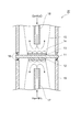
図1は、本発明に係る燃料電池の好適な実施形態を示す模式断面図である。図1の燃料電池10は、固体電解質層1と、固体電解質層1を挟むように配置されたアノード電極2及びカソード電極3を備えている。また、燃料電池10は、固体電解質層1によって内部の空間が第1領域R1及び第2領域R2に仕切られたセル本体部4を有している。
(Fuel cell)
FIG. 1 is a schematic cross-sectional view showing a preferred embodiment of a fuel cell according to the present invention. A
セル本体部4は、アノード電極2、カソード電極3及び固体電解質層1を収容するものであり、固体電解質層1によって内部の空間が第1領域R1及び第2領域R2に仕切られている。セル本体部4は、燃料電池10の燃料として、例えばアンモニアを第1領域R1内に供給するためのガス供給口5a及び第1領域R1から例えばN2、H2Oを排出するガス排出口5bを有する。ガス供給口5a及びガス排出口5bには、配管6a及び配管6bがそれぞれ接続されている。配管6aの途中には、供給するガス量を調節するバルブ(図示せず)等が配設されている。なお、本実施形態においては、燃料供給手段は、ガス供給口5a、配管6a及びガス量調節用のバルブ等によって構成される。
The
また、セル本体部4は、燃料電池10の酸化剤として、例えば酸素を水分とともに第2領域R2内に供給するためのガス供給口5c及び第2領域R2からガスを排出するガス排出口5dを有する。ガス供給口5c及びガス排出口5dには、配管6c及び配管6dがそれぞれ接続されている。配管6cの途中には、供給するガス量を調節するバルブ(図示せず)等が配設されている。なお、本実施形態においては、酸化剤供給手段は、ガス供給口5c、配管6c及びガス量調節用のバルブ等によって構成される。
Further, the cell
アノード電極2及びカソード電極3には、燃料電池10によって生じた電力を取り出すために、それぞれ導電が接続される。そのような導線としては、銅線、ニクロム線、白金線などが挙げられる。これらの導線に限定されるものではなく、動作条件などに応じて適宜選択すればよい。
Conductivity is connected to the
以下、燃料電池10におけるアノード電極2、固体電解質層1及びカソード電極3の構成について、より詳細に説明する。
Hereinafter, the structure of the
アノード電極2は、固体電解質層1の第1領域R1側に設けられ、電極触媒と第1の層状金属酸化物を含む。電極触媒は、燃料電池のアノード電極に用いることができるものであれば特に制限はない。高い起電力と十分な電流密度を達成する観点からは、Fe、Co及びNiを含む合金部分と、当該合金部分を形成していないFe部分と、を含む合金材料を有する電極触媒であることが好ましい。Fe、Co及びNiを含む合金部分とは、例えば、Fe、Co及びNiが三元系の合金をなすものをいう。Fe、Co及びNiを含む合金部分は、当該合金部分としての機能を害さない範囲で他の金属などの成分を含んでもよい。また、当該合金部分を形成していないFe部分とは、Fe、Co及びNiの三元系合金から一部のFeが析出したものをいう。この合金部分を形成していないFe部分は、例えば、Fe、Co及びNiを含む合金部分の領域外に存在しており、合金部分の領域の表面にFeが析出したものも好ましい。合金材料は、Fe、Co及びNiを含む合金部分と、当該合金部分を形成していないFe部分を含むが、当該合金材料としての機能を害さない範囲で他の金属などの成分を含んでもよい。
The
合金材料が、Feを含む合金部分と、当該合金部分を形成していないFe部分を含むことは、合金材料をX線回折(回折角2θ)を用いて構造解析したときに、Feに由来する2つのピークが発現することで確認できる。すなわち、本発明の電極触媒は、X線回折(回折角2θ)を用いて構造解析すると、43〜45°の範囲において、Feに由来する2つのピークを発現する。2つのピークは、合金部分に含まれるFeを示す第1のピークと、当該合金部分を形成していないFe部分を示す第2のピークとからなる。第1のピークと第2のピークとは、それらの裾部において必ずしも明確に2つに分離していない場合もあるが、両ピークの最も高い部分同士が、少なくとも0.5〜1°、好ましくは0.8〜1°、より好ましくは0.9〜1°離れていれば、Feに由来する2つのピークが発現していると見なすことができる。また、第2のピークの強度は、第1のピークの強度の30〜50%であればよい。この割合は、好ましくは35〜50%であり、より好ましくは40〜50%である。本発明者らは本電極触媒の上記構造が、アンモニア燃料電池に適用された場合に、高い起電力と十分な電流密度を可能としているものと推察している。 The fact that the alloy material includes an alloy part containing Fe and an Fe part not forming the alloy part is derived from Fe when the alloy material is structurally analyzed using X-ray diffraction (diffraction angle 2θ). This can be confirmed by the appearance of two peaks. That is, the structure of the electrode catalyst of the present invention using X-ray diffraction (diffraction angle 2θ) reveals two peaks derived from Fe in the range of 43 to 45 °. The two peaks are composed of a first peak indicating Fe contained in the alloy part and a second peak indicating Fe part not forming the alloy part. The first peak and the second peak may not necessarily be clearly separated into two at their skirts, but the highest portions of both peaks are at least 0.5 to 1 °, preferably Is 0.8 to 1 °, more preferably 0.9 to 1 °, it can be considered that two peaks derived from Fe are expressed. The intensity of the second peak may be 30 to 50% of the intensity of the first peak. This proportion is preferably 35 to 50%, more preferably 40 to 50%. The present inventors presume that the above-described structure of the electrode catalyst enables a high electromotive force and a sufficient current density when applied to an ammonia fuel cell.
上記電極触媒は炭素材料に、上記合金材料を担持したものであることが好ましい。ここで、炭素材料としては炭素の含有割合が高い材料が好ましく、例えばカーボンブラックを用いることができる。 The electrode catalyst is preferably a carbon material carrying the alloy material. Here, as the carbon material, a material having a high carbon content is preferable. For example, carbon black can be used.
上記電極触媒は、例えば、炭素材料を、Fe、Co及びNiを含む水溶液に含浸させ触媒前駆体を得る工程、触媒前駆体を水素雰囲気下において焼成する第1の焼成工程及び第1の焼成工程後の触媒前駆体を水素雰囲気下において第1の焼成工程よりも低温で焼成する第2の焼成工程を経ることによって調製することができる。以下、各工程について説明する。 The electrode catalyst includes, for example, a step of impregnating a carbon material in an aqueous solution containing Fe, Co and Ni to obtain a catalyst precursor, a first firing step and a first firing step of firing the catalyst precursor in a hydrogen atmosphere. It can prepare by going through the 2nd baking process which bakes a catalyst precursor after that at lower temperature than a 1st baking process in hydrogen atmosphere. Hereinafter, each step will be described.
まず、触媒前駆体を得る工程においては、Fe、Co及びNiを含む水溶液に炭素材料を含侵させ、触媒前駆体を得る。Fe、Co及びNiを含む水溶液とは、Fe、Co及びNiを所定の割合で含有している水溶液であればよく、Fe、Co及びNiの塩を水に溶解させた水溶液が好ましい。Feの塩としては例えばFe(NO3)3・9H2O、Coの塩としては例えばCo(NO3)2・6H2O、Niの塩としては例えばNi(NO3)2・6H2Oが挙げられる。 First, in the step of obtaining a catalyst precursor, a carbon material is impregnated in an aqueous solution containing Fe, Co and Ni to obtain a catalyst precursor. The aqueous solution containing Fe, Co, and Ni may be an aqueous solution containing Fe, Co, and Ni at a predetermined ratio, and an aqueous solution in which a salt of Fe, Co, and Ni is dissolved in water is preferable. Examples of the Fe salt include Fe (NO 3 ) 3 · 9H 2 O, examples of the Co salt include Co (NO 3 ) 2 · 6H 2 O, and examples of the Ni salt include Ni (NO 3 ) 2 · 6H 2 O Is mentioned.
Fe、Co及びNiを含む水溶液におけるFe、Co及びNiの割合は、Feを1としたときに、Coが0.3〜3、Niが0.3〜3であることが好ましく、Coが0.5〜2、Niが0.5〜2であることがより好ましく、Coが0.8〜1.2、Niが0.8〜1.2であることがさらに好ましく、Coが0.9〜1.1、Niが0.9〜1.1であることが特に好ましい。最も好ましくは、Fe:Co:Niが1:1:1の割合である。 The ratio of Fe, Co, and Ni in the aqueous solution containing Fe, Co, and Ni is preferably 0.3 to 3 for Co and 0.3 to 3 for Ni when Fe is 1, and 0 to Co. More preferably, Ni is 0.5-2, Co is 0.8-1.2, Ni is 0.8-1.2, and Co is 0.9. -1.1 and Ni are particularly preferably 0.9 to 1.1. Most preferably, the ratio of Fe: Co: Ni is 1: 1: 1.
Fe、Co及びNiを含む水溶液に含侵させる炭素材料としては、炭素の含有割合が高い材料が好ましく、例えばカーボンブラックを用いることができる。カーボンブラックの重量は触媒量が30〜80重量%になるように調製することが好ましく、より好ましくは40〜70重量%であり、さらに好ましくは50〜60重量%である。また、Fe、Co及びNiを含む水溶液に含侵させた炭素材料(触媒前駆体)の水分を蒸発させ、乾燥させる工程を有することが好ましい。 As the carbon material impregnated with the aqueous solution containing Fe, Co, and Ni, a material having a high carbon content is preferable, and for example, carbon black can be used. The weight of the carbon black is preferably adjusted so that the catalyst amount is 30 to 80% by weight, more preferably 40 to 70% by weight, and still more preferably 50 to 60% by weight. Moreover, it is preferable to have the process of evaporating the water | moisture content of the carbon material (catalyst precursor) impregnated with the aqueous solution containing Fe, Co, and Ni, and drying it.
次に、第1の焼成工程においては、上記工程で得られた触媒前駆体を水素雰囲気下において焼成する。第1の焼成工程における温度は、900〜1300℃であることが好ましい。900〜1300℃で焼成することによって、Fe、Co及びNiを含む合金を生成し易くなる。焼成温度は、より好ましくは1050〜1300℃であり、特に好ましくは1200〜1300℃である。急速に1200〜1300oC程度の高温にすることで、高分散で粒子径の小さい合金を形成することができる。 Next, in the first firing step, the catalyst precursor obtained in the above step is fired in a hydrogen atmosphere. The temperature in the first baking step is preferably 900 to 1300 ° C. By firing at 900 to 1300 ° C., an alloy containing Fe, Co, and Ni is easily generated. The firing temperature is more preferably 1050 to 1300 ° C, particularly preferably 1200 to 1300 ° C. By rapidly raising the temperature to about 1200 to 1300 ° C., an alloy having a high dispersion and a small particle size can be formed.
第1の焼成工程における焼成時間は、1〜120分であることが好ましく、より好ましくは1〜60分であり、さらに好ましくは1〜30分であり、特に好ましくは1〜10分であり、最も好ましくは1〜3分である。 The firing time in the first firing step is preferably 1 to 120 minutes, more preferably 1 to 60 minutes, still more preferably 1 to 30 minutes, and particularly preferably 1 to 10 minutes, Most preferably, it is 1 to 3 minutes.
次に、第2の焼成工程においては、上記第1の焼成工程後の触媒前駆体(Fe、Co及びNiを含む合金)を水素雰囲気下においてさらに焼成する。ここで、第2の焼成工程における温度は、上記第1の焼成工程よりも低温であり、第1の焼成温度よりも400〜800℃低温であると好ましく、600〜700℃低温であることがより好ましい。第1の焼成温度よりも低温でFe、Co及びNiを含む合金(第1の焼成工程後の触媒前駆体)を焼成することによって、合金部分からFeを析出させ、当該合金部分を形成していないFe部分を含む合金材料が得られ易くなる。より具体的には、第2の焼成工程における温度は、400〜600℃であることが好ましい。この焼成温度は、より好ましくは450〜550℃であり、さらに好ましくは480〜520℃である。第2の焼成温度は、第1の焼成温度との温度差よりも、500℃近辺で焼成することが特に重要であり、これにより合金部分からFeがより析出しやすくなる。 Next, in the second firing step, the catalyst precursor (an alloy containing Fe, Co, and Ni) after the first firing step is further fired in a hydrogen atmosphere. Here, the temperature in the second baking step is lower than that in the first baking step, preferably 400 to 800 ° C. lower than the first baking temperature, and 600 to 700 ° C. lower. More preferred. By firing an alloy containing Fe, Co and Ni (catalyst precursor after the first firing step) at a temperature lower than the first firing temperature, Fe is precipitated from the alloy portion to form the alloy portion. It becomes easy to obtain an alloy material containing no Fe part. More specifically, the temperature in the second baking step is preferably 400 to 600 ° C. This firing temperature is more preferably 450 to 550 ° C, and further preferably 480 to 520 ° C. It is particularly important that the second firing temperature is fired at around 500 ° C. rather than the temperature difference from the first firing temperature, which makes it easier for Fe to precipitate from the alloy portion.
第2の焼成工程における焼成時間は、0.1〜10時間であることが好ましく、より好ましくは0.5〜5時間であり、さらに好ましくは1〜5時間であり、特に好ましくは1〜4時間であり、最も好ましくは1〜3時間である。 The firing time in the second firing step is preferably 0.1 to 10 hours, more preferably 0.5 to 5 hours, still more preferably 1 to 5 hours, and particularly preferably 1 to 4 hours. Hours, most preferably 1 to 3 hours.
このように触媒前駆体を2回の工程に分けて焼成し、特に第2の焼成工程における温度を第1の焼成工程よりも低温で焼成することによって、Fe、Co及びNiを含む合金部分から一部のFe(当該合金部分を形成していないFe部分)が析出した、従来のFe−Co−Ni触媒には見られない構造を容易に発現させることができる。 In this way, the catalyst precursor is fired in two steps, and in particular, by firing the temperature in the second firing step at a lower temperature than the first firing step, from the alloy portion containing Fe, Co and Ni A structure which is not found in the conventional Fe—Co—Ni catalyst in which a part of Fe (Fe part not forming the alloy part) is precipitated can be easily developed.
なお、上記第1の焼成工程又は第2の焼成工程においては、例えば、第1の焼成工程における合金部分の形成後に、Feをさらに添加し焼成することによっても、Fe、Co及びNiを含む合金部分と、当該合金部分を形成していないFe部分と、を含む合金材料を製造することも可能である。 In the first firing step or the second firing step, for example, an alloy containing Fe, Co, and Ni can be obtained by further adding Fe and firing after the formation of the alloy portion in the first firing step. It is also possible to produce an alloy material that includes a portion and an Fe portion that does not form the alloy portion.
アノード電極2に含まれる第1の層状金属酸化物は、水蒸気処理によって水酸化物イオンの伝導性を発現し、アノード電極として用いることができるものであれば特に制限はない。第1の層状酸化物の含有量は、電極触媒100重量部に対して50〜150重量部である。第1の層状酸化物が電極触媒100重量部に対して50重量部未満、又は、150重量部より大きいと、燃料電池のアノード電極として用いた場合に、電流密度が不十分となったりする。好ましくは第1の層状酸化物は、電極触媒100重量部に対して、60〜140重量部であり、より好ましくは70〜130重量部である。
The first layered metal oxide contained in the
カソード電極3は、固体電解質層1の第2領域R2側に設けられ、カーボン材料と第2の層状金属酸化物を含む。カーボン材料としては、炭素の含有割合が高い材料が好ましく、例えば、カーボンブラックを適用できる。第2の層状金属酸化物は、水蒸気処理を施されたものでなく、燃料電池のカソード電極に用いることができるものであれば特に制限されない。第2の層状酸化物の含有量は、カーボン材料100重量部に対して150〜250重量部である。第2の層状酸化物がカーボン材料100重量部に対して150重量部未満、又は、250重量部より大きいと、燃料電池のカソード電極として用いた場合に、電圧が低下したり電流密度が不十分となったりする。好ましくは第2の層状酸化物は、カーボン材料100重量部に対して、180〜250重量部であり、より好ましくは200〜250重量部である。
The
アノード電極2は、固体電解質層1の第1領域R1側に直接設けられてもよく、カソード電極3は、固体電解質層1の第2領域R2側に直接設けられてもよいが、担体上に形成されてもよい。担体となる材料は、導電性を有し、ポーラスで微細構造を持つものであれば特に制限はされず、例えば、発泡Niやカーボンペーパー、カーボンクロス、ステンレスメッシュなどを用いることができる。
The
固体電解質層1は、アノード電極2とカソード電極3との間に配置され、第3の層状金属酸化物を含む。第3の層状金属酸化物は、水蒸気処理によって水酸化物イオンの伝導性を発現し、燃料電池の固体電解質層として用いることができるものであれば特に制限はない。
The
固体電解質層1は、高いイオン伝導性を達成する観点から、固体電解質層1内には空隙がなるべく少ないことが好ましい。固体電解質層1の厚さは、燃料電池の用途や動作条件などに応じて適宜設定すればよいが、0.3〜3mmであることが好ましく、0.5〜2mmであることがより好ましく、0.5〜1.5mmであることがさらに好ましく、0.8〜1.2mmであることが特に好ましい。固体電解質層1の厚さが0.3mm未満であると、固体電解質層1の強度が不十分となる傾向があり、アノード支持型のディスクを用いる必要がある。他方、固体電解質層1の厚さが3mmを超えると、内部抵抗が増大する傾向がある。
The
アノード電極2、カソード電極3及び固体電解質層1に含まれる第1、第2及び第3の層状金属酸化物は、それぞれ同一でも異なっていてもよい。第1、第2及び第3の層状金属酸化物は、高い起電力及び十分な電流密度を達成する観点から、下記一般式(1)で表される層状金属酸化物、又は、NaCo2O4であることが好ましい。
(La1−xAx)(Sr1−yBy)3(Co1−zCz)3O10−δ (1)
[式中、AはLa以外の希土類元素であり、BはMg、Ca又はBaであり、CはTi、V、Cr又はMnであり、0≦x<1、0≦y<1、0≦z<1、δは酸素欠損量である。]
The first, second, and third layered metal oxides included in the
(La 1-x A x) (Sr 1-y B y) 3 (Co 1-z C z) 3 O 10-δ (1)
[In the formula, A is a rare earth element other than La, B is Mg, Ca, or Ba, C is Ti, V, Cr, or Mn, and 0 ≦ x <1, 0 ≦ y <1, 0 ≦ z <1, δ is the amount of oxygen deficiency. ]
上記一般式(1)で表される層状金属酸化物において、式(1)中、AはLaサイトに含まれる元素であり、La(ランタン)以外の希土類元素であること好ましい。La(ランタン)以外の希土類元素とは、Sc(スカンジウム)、Y(イットリア)、Ce(セリウム)、Pr(プラセオジウム)、Nd(ネオジム)、Pm(プロメチウム)、Sm(サマリウム)、Eu(ユーロピウム)、Gd(ガドリニウム)、Tb(テルビウム)、Dy(ジスプロシウム)、Ho(ホルミウム)、Er(エルビウム)、Tm(ツリウム)、Yb(イッテルビウム)又はLu(ルテチウム)である。この中でも、より好ましくはAはY、Sc、Ce、Eu、Sm、Gd、Pr、Ndであり、さらに好ましくはY、Eu、Sm、Gd、Ndである。また、xは0以上1未満であることが好ましく、より好ましくは0以上0.5以下であり、さらに好ましくは0以上0.1以下である。 In the layered metal oxide represented by the general formula (1), in the formula (1), A is an element contained in the La site, and is preferably a rare earth element other than La (lanthanum). The rare earth elements other than La (lanthanum) are Sc (scandium), Y (yttria), Ce (cerium), Pr (praseodymium), Nd (neodymium), Pm (promethium), Sm (samarium), Eu (europium). , Gd (gadolinium), Tb (terbium), Dy (dysprosium), Ho (holmium), Er (erbium), Tm (thulium), Yb (ytterbium) or Lu (lutetium). Among these, A is more preferably Y, Sc, Ce, Eu, Sm, Gd, Pr, Nd, and more preferably Y, Eu, Sm, Gd, Nd. X is preferably 0 or more and less than 1, more preferably 0 or more and 0.5 or less, and even more preferably 0 or more and 0.1 or less.
BはSrサイトに含まれる元素であり、Mg、Ca又はBaであることが好ましく、より好ましくはBは、Ca又はBaである。また、yは0以上1未満であることが好ましく、より好ましくは0以上0.5以下であり、さらに好ましくは0以上0.1以下である。 B is an element contained in the Sr site, and is preferably Mg, Ca or Ba, and more preferably B is Ca or Ba. Further, y is preferably 0 or more and less than 1, more preferably 0 or more and 0.5 or less, and still more preferably 0 or more and 0.1 or less.
CはCoサイトに含まれる元素であり、Ti、V、Cr、Fe又はMnであることが好ましく、より好ましくはCは、Mn、Fe又はCrであり、さらに好ましくはMn又はFeである。また、zは0以上1未満であることが好ましく、より好ましくは0以上0.5以下であり、さらに好ましくは0以上0.1以下である。 C is an element contained in the Co site, and is preferably Ti, V, Cr, Fe or Mn, more preferably C is Mn, Fe or Cr, and further preferably Mn or Fe. Z is preferably 0 or more and less than 1, more preferably 0 or more and 0.5 or less, and still more preferably 0 or more and 0.1 or less.
また、δは酸素欠損量を示し、−0.2以上1.5以下の酸素欠損が生じる。すなわち、式(1)中の酸素の価数(原子価)は、8.5以上10.2以下となる。 Further, δ represents the amount of oxygen deficiency, and oxygen deficiency of −0.2 or more and 1.5 or less occurs. That is, the valence (valence) of oxygen in formula (1) is 8.5 or more and 10.2 or less.
上記一般式(1)で示される層状金属酸化物は、水蒸気処理が施されると当該層状金属酸化物中の酸素欠陥に水分子が水和し、水酸化物イオンの伝導性が発現すると推察される。ここで、アノード電極2に含まれる第1の層状金属酸化物及び固体電解質層1に含まれる第3の層状金属酸化物は、水蒸気処理が施されたものである。水蒸気処理が施された第1の層状金属酸化物を含有するアノード電極2及び第3の層状金属酸化物を含有する固体電解質層1を燃料電池に採用することで、室温であっても十分に高い起電力を得ることができる。
The layered metal oxide represented by the general formula (1) is presumed that when water vapor treatment is performed, water molecules are hydrated by oxygen defects in the layered metal oxide, and the conductivity of hydroxide ions is expressed. Is done. Here, the first layered metal oxide contained in the
水蒸気処理は、固体電解質層1やアノード電極2を、所定の温度、相対湿度及び圧力の条件にさらすことによって実施することができる。その条件は、水酸化物イオンの伝導性が発現する範囲で適宜設定することが好ましい。例えば、温度を50〜120℃の範囲とし、相対湿度を50〜90%の範囲とし、圧力を0.1〜1MPaの範囲とし、処理時間を2〜48時間の範囲とすることが好ましい。なお、水蒸気処理の温度が高すぎると上記電解質層や電極が脆くなり、性能が低下する場合がある。
The steam treatment can be performed by exposing the
また、上記層状金属酸化物は緻密性が高いことから、例えば、アンモニアを燃料とした場合においてもガスリークしにくいという点でも優れる。また、水素や、エチレングリコール及びメタノールなどの水素含有化合物も燃料として用いることができる。 In addition, since the layered metal oxide has high density, it is excellent in that gas leakage is difficult even when ammonia is used as a fuel. Moreover, hydrogen and hydrogen containing compounds, such as ethylene glycol and methanol, can also be used as a fuel.
上記一般式(1)で表される層状金属酸化物を得るには、例えば、La、Sr及びCoを所定の比率で含む水溶液をアルカリ水溶液に加える工程により、上記一般式(1)で表される層状金属酸化物の前駆体を含む沈殿物を生じさせる。この沈殿物を乾燥させ、600〜900℃で15〜60分焼成する工程によって、上記一般式(1)で表される層状金属酸化物を得ることができる。 In order to obtain the layered metal oxide represented by the general formula (1), for example, a step of adding an aqueous solution containing La, Sr and Co in a predetermined ratio to the alkaline aqueous solution is represented by the general formula (1). Resulting in a precipitate containing a precursor of the layered metal oxide. The layered metal oxide represented by the above general formula (1) can be obtained by drying the precipitate and baking it at 600 to 900 ° C. for 15 to 60 minutes.
一方、NaCo2O4を得るには、例えば、酢酸ナトリウムと酢酸コバルト四水和物を所定の比率で溶解させた溶液を乾燥させ、得られた試料の粉砕・仮焼成を行う。仮焼成後の試料を粉砕した後、ペレットに成型した状態で750〜850℃程度の温度で再度焼成を行う。その後、焼成後のペレットの粉砕・ペレット化を行い、900〜1000℃程度の温度で焼結させることにより、層状の結晶構造を有するNaCo2O4が得られる。 On the other hand, in order to obtain NaCo 2 O 4 , for example, a solution in which sodium acetate and cobalt acetate tetrahydrate are dissolved in a predetermined ratio is dried, and the obtained sample is pulverized and calcined. After the pre-baked sample is pulverized, it is fired again at a temperature of about 750 to 850 ° C. in a state of being formed into pellets. Thereafter, the fired pellets are pulverized and pelletized, and sintered at a temperature of about 900 to 1000 ° C. to obtain NaCo 2 O 4 having a layered crystal structure.
(発電方法)
次に、燃料電池10を用いた発電方法について説明する。水酸化物イオンの伝導性を発現させるためには、燃料電池10による発電を開始するに先立ち、固体電解質層1及びアノード電極2をなす層状金属酸化物(好ましくは上記一般式(1)で表されるもの又はNaCo2O4)の水蒸気処理を行う。固体電解質層1及びアノード電極2を構成する層状金属酸化物を水蒸気処理することにより、当該層状金属酸化物中の酸素欠陥に水分子が水和する。これによって、水酸化物イオンの伝導性が発現する。燃料電池10は、例えばアンモニアを燃料として用いる場合には、水酸化物イオン(OH−)が燃料電池のイオン伝導体となり、アニオン交換型の燃料電池に分類される。
(Power generation method)
Next, a power generation method using the
固体電解質層1及びアノード電極2の水蒸気処理は、例えば、セル本体部4内(第1領域R1及び第2領域R2)を所定の温度、相対湿度及び圧力に調整して行うことができる。この際、カソード電極3には、水蒸気処理されないように措置する。水酸化物イオンの伝導性が発現する限り、水蒸気処理の条件は特に制限されないが、水蒸気処理の作業効率及び水蒸気処理後の伝導度等の観点から下記の条件が好ましい。すなわち、水蒸気処理における温度は20〜150℃であることが好ましく、40〜130℃であることがより好ましく、50〜120℃であることが更に好ましい。水蒸気処理における相対湿度は30〜100%であることが好ましく、40〜90%であることがより好ましく、50〜90%であることが更に好ましい。水蒸気処理における圧力は0.1〜1MPaであることが好ましく、0.1〜0.8MPaであることがより好ましく、0.2〜0.5MPaであることが更に好ましい。水蒸気処理の処理時間は、2〜48時間であることが好ましく、3〜24時間であることがより好ましい。
The water vapor treatment of the
また、固体電解質層1及びアノード電極2には、水蒸気処理の前、又は、同時に水素処理を施すことが好ましい。水素処理は、例えば、セル本体部4の第1領域R1内を所定の温度及び圧力に調整した状態で水素を供給することによって実施できる。アノード電極2の電極触媒が十分に高い触媒活性が発現する限り、水素処理の条件は特に制限されないが、水素処理の作業効率及び水素処理後の触媒活性等の観点から下記の条件が好ましい。すなわち、水素処理における温度は200〜400℃であることが好ましく、100〜350℃であることがより好ましい。水素処理における圧力は0.1〜1MPaであることが好ましく、0.1〜0.8MPaであることがより好ましい。水素処理における水素濃度は10〜100体積%であることが好ましく、20〜80体積%であることがより好ましい。水素処理の処理時間は、2〜48時間であることが好ましく、3〜24時間であることがより好ましい。
The
水蒸気処理を行った後、燃料電池10の燃料として、例えばアンモニアを含有するガスを第1領域R1に供給することによって、アノード電極2では下記式(2)で表される反応が進行する。一方、燃料電池10の酸化剤として、O2及びH2Oを含有するガスを第2領域R2に供給することによって、カソード電極3では下記式(3)で表される反応が進行する。第2領域R2に供給するガスは、酸素及び水分を含んだものであればよく、加湿した酸素及び加湿した空気を使用できる。
NH3+3OH− → 1/2N2+3H2O+3e− (2)
3/4O2+3/2H2O+3e− → 3OH− (3)
After performing the water vapor treatment, by supplying, for example, a gas containing ammonia as the fuel of the
NH 3 + 3OH − → 1 / 2N 2 + 3H 2 O + 3e − (2)
3 / 4O 2 + 3 / 2H 2 O + 3e − → 3OH − (3)
上記構成の燃料電池10は、動作温度が10〜800℃であり、範囲が広い。したがって、このような燃料電池10によれば、比較的低い温度条件、例えば、20〜80℃で発電を十分に行うことができる。
The
以上のとおり、本発明の燃料電池は、電極触媒と第1の層状金属酸化物を含み、電極触媒100重量部に対して第1の層状酸化物が50〜150重量部であるアノード電極と、カーボン材料と第2の層状金属酸化物含み、カーボン材料100重量部に対して第2の層状酸化物が150〜250重量部であるカソード電極と、アノード電極とカソード電極との間に配置され第3の層状金属酸化物を含む固体電解質層とを備え、第1及び第3の層状金属酸化物は水蒸気処理が施されたものであることによって、高い起電力及び十分な電流密度を得ることが可能となる。 As described above, the fuel cell of the present invention includes an anode catalyst containing an electrode catalyst and a first layered metal oxide, and the first layered oxide is 50 to 150 parts by weight with respect to 100 parts by weight of the electrode catalyst, A cathode electrode comprising a carbon material and a second layered metal oxide, wherein the second layered oxide is 150 to 250 parts by weight with respect to 100 parts by weight of the carbon material, and is disposed between the anode electrode and the cathode electrode. 3 and a solid electrolyte layer containing a layered metal oxide, and the first and third layered metal oxides are subjected to water vapor treatment, so that a high electromotive force and a sufficient current density can be obtained. It becomes possible.
以上、本発明の好適な実施形態について詳細に説明したが、本発明は上記実施形態に限定されるものではない。 The preferred embodiment of the present invention has been described in detail above, but the present invention is not limited to the above embodiment.
以下、実施例により本発明を説明するが、本発明はこれら実施例に限定されるものではない。 EXAMPLES Hereinafter, although an Example demonstrates this invention, this invention is not limited to these Examples.
(実施例1)
<Fe−Co−Ni電極触媒の調製>
まず、Fe:Co:Niが1:1:1になるように、Fe(NO3)3・9H2Oを2.86g、Co(NO3)2・6H2Oを2.08g、Ni(NO3)2・6H2Oを2.08g、蒸留水10ml中に溶解させ、Fe、Co及びNiを含む硝酸塩水溶液を用意した。この硝酸塩水溶液に、カーボンブラック(Vulcan XC72)を得られる合金材料が55重量%になるように1.00g、蒸留水10mlを攪拌しながら加え、水浴上で水分を蒸発させ、80℃のオーブンで一晩乾燥させた。
Example 1
<Preparation of Fe-Co-Ni Electrocatalyst>
First, 2.86 g of Fe (NO 3 ) 3 .9H 2 O, 2.08 g of Co (NO 3 ) 2 .6H 2 O, and Ni (NO) so that Fe: Co: Ni is 1: 1: 1. NO 3 ) 2 · 6H 2 O was dissolved in 2.08 g of distilled
乾燥させた粉末を水素雰囲気下(H2/Ar 60ml/min)、1200℃(昇温速度:100K/min)で3分間焼成した。その後、自然冷却し、焼成した粉末をさらに同様の水素雰囲気下500℃を保持し、2時間焼成した。
The dried powder was fired at 1200 ° C. (temperature increase rate: 100 K / min) for 3 minutes in a hydrogen atmosphere (H 2 /
<NaCo2O4焼結体の調製>
本調製においては、以下の試薬を使用したが、他のものを適宜使用してもよい。
酢酸ナトリウム(CH3COONa、関東化学 特級)
酢酸コバルト四水和物((CH3COO)2Co・4H2O、和光純薬 鹿特級)
ジニトロジアンミンパラジウム(Pd(NO2)2(NH3)2、田中貴金属)
エチレングリコール(HOCH2CH2OH、和光純薬 特級)
<Preparation of NaCo 2 O 4 sintered body>
In this preparation, the following reagents were used, but other reagents may be used as appropriate.
Sodium acetate (CH 3 COONa, Kanto Chemical Special Grade)
Cobalt acetate tetrahydrate ((CH 3 COO) 2 Co.4H 2 O, Wako Pure Chemicals Shika Special Grade)
Dinitrodiammine palladium (Pd (NO 2 ) 2 (NH 3 ) 2 , Tanaka Kikinzoku)
Ethylene glycol (HOCH 2 CH 2 OH, Wako Pure Chemical)
NaCo2O4焼結体を以下の(1)〜(5)の手順に従って調製した。なお、本実施例においては、NaCo2O4ペレットは、後述の通り、温度900℃程度の焼成過程を経て作製されるものであり、このような高温条件にあっては、Naが蒸発する。したがって、理論量のモル比(Na:Co=1:2)で原料を調製すると、生成物中に不純物(Co3O4)が生じてしまうため、ここでは、原料中のNaとCoのモル比をNa:Co=1.6:2とした。
(1)酢酸ナトリウム5.00g(60.95mmol)と酢酸コバルト四水和物19.00g(76.28mmol)を内容積200mLのテフロン(登録商標)製のビーカーに秤取し、蒸留水40mLを用いて溶解した。
(2)上記(1)で得た溶液を80℃で撹拌しながら水分を蒸発させ、乾燥機(温度条件:80℃)に入れて、一晩乾燥させた。
(3)乾燥させた試料をメノウ乳鉢でよく粉砕し、これをアルミナるつぼに入れた。このるつぼをMuffle炉に入れ、試料を空気中にて温度750℃、保持時間5時間の条件で仮焼きした。
(4)仮焼きした試料をメノウ乳鉢で粉砕し、錠剤成型器を用いてペレット(直径:20mm、厚さ:〜3mm)に成型した(圧力:30MPa、保持時間:5分)。得られた成型体をMuffle炉内に入れ、空気中にて温度790℃、保持時間3時間の条件で本焼きした。
(5)本焼きした試料を遊星型ボールミル(FRITSCH pulverisette)に収容し、回転速度300rpm、処理時間20分の条件で粉砕した。得られた粉体を錠剤成型器に入れてペレット(直径:10mm、厚さ:1.7〜12mm)に成型した。なお、ペレットの厚さが6mm以下の場合は、圧力30MPa、保持時間5分、ペレットの厚さが12mm程度の場合は、圧力40MPa、保持時間5分の条件で成型した。得られた成型体をMuffle炉内に入れ、空気中にて温度900℃、保持時間32時間の条件で焼結させ、NaCo2O4の焼結体を得た。
A NaCo 2 O 4 sintered body was prepared according to the following procedures (1) to (5). In this embodiment, the NaCo 2 O 4 pellet is produced through a firing process at a temperature of about 900 ° C. as will be described later, and Na evaporates under such a high temperature condition. Therefore, when the raw material is prepared at a theoretical molar ratio (Na: Co = 1: 2), impurities (Co 3 O 4 ) are generated in the product. Here, the moles of Na and Co in the raw material are here. The ratio was Na: Co = 1.6: 2.
(1) Weigh 5.00 g (60.95 mmol) of sodium acetate and 19.00 g (76.28 mmol) of cobalt acetate tetrahydrate in a 200 mL Teflon (registered trademark) beaker, and add 40 mL of distilled water. Used to dissolve.
(2) While stirring the solution obtained in the above (1) at 80 ° C., water was evaporated, put into a dryer (temperature condition: 80 ° C.) and dried overnight.
(3) The dried sample was pulverized well in an agate mortar and placed in an alumina crucible. The crucible was placed in a Muffle furnace, and the sample was calcined in air at a temperature of 750 ° C. and a holding time of 5 hours.
(4) The calcined sample was pulverized in an agate mortar and formed into pellets (diameter: 20 mm, thickness: ˜3 mm) using a tablet molding machine (pressure: 30 MPa, holding time: 5 minutes). The obtained molded body was placed in a Muffle furnace and baked in air at a temperature of 790 ° C. and a holding time of 3 hours.
(5) The main-baked sample was placed in a planetary ball mill (FRITSCH pulverisete) and pulverized under conditions of a rotation speed of 300 rpm and a processing time of 20 minutes. The obtained powder was put into a tablet molding machine and molded into pellets (diameter: 10 mm, thickness: 1.7-12 mm). In addition, when the thickness of the pellet was 6 mm or less, it was molded under the conditions of a pressure of 30 MPa and a holding time of 5 minutes, and when the thickness of the pellet was about 12 mm, the pressure was 40 MPa and the holding time was 5 minutes. The obtained molded body was put in a Muffle furnace and sintered in air at a temperature of 900 ° C. and a holding time of 32 hours to obtain a NaCo 2 O 4 sintered body.
<アノード電極の調製>
上記で得られたFe−Co−Ni電極触媒と、NaCo2O4焼結体(第1の層状金属酸化物)を1:1の割合になるようにそれぞれ0.01gをアルミナ乳鉢で粉砕し、混合した。この混合物にエチレングリコールを5μl加えペースト状にし、発泡Ni上に塗布した。この発泡NiをHe雰囲気下で400℃まで昇温させ、エチレングリコールを除去した。除去後の発泡Niにおける金属担持量は10mg/cm2であった。
<Preparation of anode electrode>
0.01 g of the Fe—Co—Ni electrode catalyst obtained above and the NaCo 2 O 4 sintered body (first layered metal oxide) were pulverized in an alumina mortar so as to have a ratio of 1: 1. , Mixed. To this mixture, 5 μl of ethylene glycol was added to form a paste, which was applied onto foamed Ni. The foamed Ni was heated to 400 ° C. in a He atmosphere to remove ethylene glycol. The metal loading in the foamed Ni after removal was 10 mg / cm 2 .
<カソード電極の調製>
上記で得られたNaCo2O4焼結体(第2の層状金属酸化物)と、カーボンブラック(Vulcan XC72)を2:1の割合になるようにそれぞれ10mg、5mgをエタノール中に分散させ、カーボンペーパー(製品名:P50T、バラードマテリアルプロダクツ社製)上に塗布した。その後、一晩乾燥させた。乾燥後のNaCo2O4担持量は10mg/cm2であった。
<Preparation of cathode electrode>
Disperse the NaCo 2 O 4 sintered body (second layered metal oxide) obtained above and carbon black (Vulcan XC72) in a ratio of 2: 1 to 10 mg and 5 mg, respectively, in ethanol, It applied on carbon paper (product name: P50T, manufactured by Ballard Material Products). Then, it was dried overnight. The amount of NaCo 2 O 4 supported after drying was 10 mg / cm 2 .
<固体電解質層の調製>
まず、第3の層状金属酸化物として、La:Sr:Coが1:3:3になるように、La(NO3)3・6H2Oを1.759g、Sr(NO3)2を2.580g、Co(NO3)2・6H2Oを3.548g、蒸留水100ml中に溶解させた、金属塩を含む水溶液を準備した。次にアルカリ水溶液として、Na2CO315gを水100mlに溶解させたNa2CO3水溶液(Na2CO3=0.14モル、CO3 2−/M=5)を準備した。共沈法として、このNa2CO3水溶液を攪拌させながら、金属塩を含む水溶液を2〜3秒で一気にNa2CO3水溶液に加え、1時間攪拌した後、20時間静置させた。
<Preparation of solid electrolyte layer>
First, as the third layered metal oxide, 1.759 g La (NO 3 ) 3 .6H 2 O and 2 Sr (NO 3 ) 2 so that La: Sr: Co is 1: 3: 3. An aqueous solution containing a metal salt was prepared by dissolving .580 g, 3.548 g of Co (NO 3 ) 2 .6H 2 O in 100 ml of distilled water. Next, an aqueous Na 2 CO 3 solution (Na 2 CO 3 = 0.14 mol, CO 3 2− / M = 5) in which 15 g of Na 2 CO 3 was dissolved in 100 ml of water was prepared as an aqueous alkaline solution. As a coprecipitation method, while stirring this Na 2 CO 3 aqueous solution, an aqueous solution containing a metal salt was added to the Na 2 CO 3 aqueous solution at a stretch in 2 to 3 seconds, stirred for 1 hour, and allowed to stand for 20 hours.
20時間静置後、上記混合水溶液中に生成した沈殿物を、遠心分離装置(製品名:テーブルトップ遠心機5420、(株)久保田製作所製)により、水で5回、エタノールで3回洗浄した。洗浄後の沈殿物を一晩空気中で乾燥(風乾)させ、乾燥させた粉末を800℃で30分仮焼した(昇温速度:10K/min)。この仮焼粉末を直径20mm、厚さ1mmのペレット状に成型し(圧力:60MPa、保持時間:10分)、1000℃で30分焼成して、固体電解質層であるLaSr3Co3O10ペレットを得た(昇温速度:10K/min)。 After standing for 20 hours, the precipitate formed in the mixed aqueous solution was washed 5 times with water and 3 times with ethanol using a centrifuge (product name: table top centrifuge 5420, manufactured by Kubota Corporation). . The washed precipitate was dried overnight in air (air-dried), and the dried powder was calcined at 800 ° C. for 30 minutes (temperature increase rate: 10 K / min). The calcined powder is molded into a pellet shape having a diameter of 20 mm and a thickness of 1 mm (pressure: 60 MPa, holding time: 10 minutes), and calcined at 1000 ° C. for 30 minutes to form a LaSr 3 Co 3 O 10 pellet as a solid electrolyte layer. (Temperature increase rate: 10 K / min) was obtained.
<発電試験>
上記で得られたアノード電極、カソード電極及び固体電解質層を用いて、図2の評価装置(燃料電池20)を準備した。燃料電池20は、固体電解質層11の一方の側にアノード電極12を、もう一方の側にカソード電極13を備える。また、アノード電極12側には燃料ガス供給口17、カソード電極13側には酸素ガス供給口18を設け、さらに、ガスが燃料電池20から漏れないように、それらの外側にセル本体部19を配置するとともに、セル本体部19と固体電解質層11との間にガスケット16を配置した。この燃料電池20においては、アノード電極12及びカソード電極13の面上にPt網14を配置し、これに接続された導線15(Pt線)からの出力を測定した。また、この燃料電池20においては、燃料をアンモニアとした。
<Power generation test>
The evaluation apparatus (fuel cell 20) of FIG. 2 was prepared using the anode electrode, cathode electrode, and solid electrolyte layer obtained above. The
測定は、以下の手順に従って行った。
(1)LaSr3Co3O10ペレット(固体電解質層11)を280℃に昇温させ、室温で加湿した水素を5ml/分で30分流し、前処理した。
(2)Fe−Co−Ni/C触媒とNaCo2O4を面上に有する発泡Ni(アノード電極12)を280℃に昇温させ、室温で加湿した水素を5ml/分で30分流し、前処理した。
(3)アノード電極12にアンモニアとHeの混合ガスを20ml/分で供給するとともに、カソード電極13に酸素を20ml/分で85℃加湿されたものを供給した。
(4)セル温度は80℃とした。
The measurement was performed according to the following procedure.
(1) The LaSr 3 Co 3 O 10 pellet (solid electrolyte layer 11) was heated to 280 ° C., and pretreated by flowing hydrogen humidified at room temperature at 5 ml / min for 30 minutes.
(2) The foamed Ni (anode electrode 12) having Fe—Co—Ni / C catalyst and NaCo 2 O 4 on the surface was heated to 280 ° C., and hydrogen humidified at room temperature was allowed to flow at 5 ml / min for 30 minutes, Pre-processed.
(3) A mixed gas of ammonia and He was supplied to the
(4) The cell temperature was 80 ° C.
(比較例1)
アノード電極12の調製において、Fe−Co−Ni合金触媒とNaCo2O4焼結体の割合(重量比)を2:1にした以外は、実施例1と同様に、燃料電池を構成し発電試験を行った。
(Comparative Example 1)
In the preparation of the
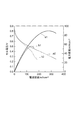
実施例1及び比較例1の発電試験で得られたデータを対比させた結果を図3に示す。図3は、上記の測定条件で燃料電池20を動作させたときの、得られる電流密度(mAcm−2)の値に対する、そのときのセル電圧(V)及び電力密度(mAcm−2)の値を示すグラフである。図3におけるa1及びa2は、実施例1で得られたセル電圧及び電力密度をそれぞれ示し、b1及びb2は、比較例1で得られたセル電圧及び電力密度をそれぞれ示す。図3のa1及びa2のとおり、実施例1の燃料電池は、OCVは0.8V以上であり、電流密度も300mA/cm2以上にすることができ、電力密度も90mW/cm2と高い性能を示した。一方、図3のb1及びb2のとおり、比較例1の燃料電池は、OCVは0.8V、電流密度は200mA/cm2以下であり、電力密度も48mW/cm2と実施例1と比較して低い性能を示した。
FIG. 3 shows the result of comparing the data obtained in the power generation test of Example 1 and Comparative Example 1. FIG. 3 shows values of the cell voltage (V) and power density (mAcm −2 ) at that time with respect to the value of current density (mAcm −2 ) obtained when the
(比較例2)
カソード電極13の調製において、NaCo2O4焼結体と、カーボンブラック(Vulcan XC72)を5:1の割合になるようにした以外は、実施例1と同様に、燃料電池を構成し発電試験を行った。
(Comparative Example 2)
In the preparation of the
実施例1及び比較例1の発電試験で得られたデータを対比させた結果を図4に示す。図4は、上記の測定条件で燃料電池20を動作させたときの、得られる電流密度(mAcm−2)の値に対する、そのときのセル電圧(V)及び電力密度(mAcm−2)の値を示すグラフである。図4におけるa1及びa2は、実施例1で得られたセル電圧及び電力密度をそれぞれ示し、b1及びb2は、比較例2で得られたセル電圧及び電力密度をそれぞれ示す。図4のb1及びb2に示すとおり、比較例2の燃料電池は、OCVは0.8V、電流密度は100mA/cm2以下であり、また電力密度も26mW/cm2と、a1及びa2に示す実施例1と比較して低い性能を示した。
FIG. 4 shows the result of comparing the data obtained in the power generation test of Example 1 and Comparative Example 1. FIG. 4 shows values of the cell voltage (V) and the power density (mAcm −2 ) at that time with respect to the obtained current density (mAcm −2 ) when the
1、11…固体電解質層、2、12…アノード電極、3、13…カソード電極、4、19…セル本体部、5a、5c、17、18…ガス供給口、5b、5d…ガス排出口、6a〜6d…配管、10、20…燃料電池。
DESCRIPTION OF
Claims (4)
カーボン材料と、第2の層状金属酸化物と、を含み、前記カーボン材料100重量部に対して、前記第2の層状酸化物が150〜250重量部である、カソード電極と、
前記アノード電極と前記カソード電極との間に配置され、第3の層状金属酸化物を含む固体電解質層と、を備え、
前記第1及び第3の層状金属酸化物は水蒸気処理が施されたものである、燃料電池。 An anode electrode comprising: an electrode catalyst; and a first layered metal oxide, wherein the first layered oxide is 50 to 150 parts by weight with respect to 100 parts by weight of the electrode catalyst;
A cathode electrode comprising a carbon material and a second layered metal oxide, wherein the second layered oxide is 150 to 250 parts by weight with respect to 100 parts by weight of the carbon material;
A solid electrolyte layer disposed between the anode electrode and the cathode electrode and including a third layered metal oxide,
The fuel cell, wherein the first and third layered metal oxides are subjected to steam treatment.
(La1−xAx)(Sr1−yBy)3(Co1−zCz)3O10−δ (1)
[式中、AはLa以外の希土類元素であり、BはMg、Ca又はBaであり、CはTi、V、Cr又はMnであり、0≦x<1、0≦y<1、0≦z<1、δは酸素欠損量である。] The first, second and third layered metal oxides may be the same or different, and may be a layered metal oxide represented by the following general formula (1) or NaCo 2 O 4 . The fuel cell according to claim 1 or 2, wherein
(La 1-x A x) (Sr 1-y B y) 3 (Co 1-z C z) 3 O 10-δ (1)
[In the formula, A is a rare earth element other than La, B is Mg, Ca, or Ba, C is Ti, V, Cr, or Mn, and 0 ≦ x <1, 0 ≦ y <1, 0 ≦ z <1, δ is the amount of oxygen deficiency. ]
Priority Applications (2)
| Application Number | Priority Date | Filing Date | Title |
|---|---|---|---|
| JP2011026121A JP5276131B2 (en) | 2011-02-09 | 2011-02-09 | Fuel cell comprising an electrode comprising a layered metal oxide and a solid electrolyte layer |
| US13/368,071 US8986894B2 (en) | 2011-02-09 | 2012-02-07 | Solid electrolyte including layered metal oxide, fuel cell including thereof, production method for solid electrolyte, and production method for electrode catalyst |
Applications Claiming Priority (1)
| Application Number | Priority Date | Filing Date | Title |
|---|---|---|---|
| JP2011026121A JP5276131B2 (en) | 2011-02-09 | 2011-02-09 | Fuel cell comprising an electrode comprising a layered metal oxide and a solid electrolyte layer |
Publications (2)
| Publication Number | Publication Date |
|---|---|
| JP2012164609A true JP2012164609A (en) | 2012-08-30 |
| JP5276131B2 JP5276131B2 (en) | 2013-08-28 |
Family
ID=46843792
Family Applications (1)
| Application Number | Title | Priority Date | Filing Date |
|---|---|---|---|
| JP2011026121A Active JP5276131B2 (en) | 2011-02-09 | 2011-02-09 | Fuel cell comprising an electrode comprising a layered metal oxide and a solid electrolyte layer |
Country Status (1)
| Country | Link |
|---|---|
| JP (1) | JP5276131B2 (en) |
Cited By (3)
| Publication number | Priority date | Publication date | Assignee | Title |
|---|---|---|---|---|
| JP2014067565A (en) * | 2012-09-25 | 2014-04-17 | Nippon Shokubai Co Ltd | Solid oxide type fuel cell, method for manufacturing the same and method for power generating using the same |
| JP2014216297A (en) * | 2013-04-30 | 2014-11-17 | 日本特殊陶業株式会社 | Single cell for fuel battery, fuel battery, and method for producing single cell for fuel battery |
| CN110010908A (en) * | 2019-04-09 | 2019-07-12 | 深圳市致远动力科技有限公司 | A fuel cell and battery stack |
Citations (8)
| Publication number | Priority date | Publication date | Assignee | Title |
|---|---|---|---|---|
| JP2001093325A (en) * | 1999-09-27 | 2001-04-06 | Tatsuki Ishihara | LaGaO3-based electron-oxygen ion mixed conductor and oxygen permeable membrane using the same |
| JP2004083392A (en) * | 2002-06-28 | 2004-03-18 | Nissan Motor Co Ltd | Lanthanum gallate-based sintered body, method for producing the same, and solid oxide fuel cell using the same as solid electrolyte |
| US20040231143A1 (en) * | 1999-07-31 | 2004-11-25 | The Regents Of The University Of California | Method of making a layered composite electrode/electrolyte |
| JP2005166397A (en) * | 2003-12-02 | 2005-06-23 | Central Res Inst Of Electric Power Ind | Oxygen ion conductor using layered cobalt oxide and fuel cell using the same |
| JP2005285451A (en) * | 2004-03-29 | 2005-10-13 | Sumitomo Electric Ind Ltd | Electrolyte membrane and method for producing the same |
| JP2008034271A (en) * | 2006-07-31 | 2008-02-14 | Toyota Motor Corp | Fuel cell |
| WO2010007949A1 (en) * | 2008-07-15 | 2010-01-21 | 国立大学法人 北海道大学 | Fuel cell and electricity generation method using the same |
| JP2010238547A (en) * | 2009-03-31 | 2010-10-21 | Equos Research Co Ltd | Fuel cell catalyst carrier, fuel cell catalyst, and fuel cell electrode |
-
2011
- 2011-02-09 JP JP2011026121A patent/JP5276131B2/en active Active
Patent Citations (8)
| Publication number | Priority date | Publication date | Assignee | Title |
|---|---|---|---|---|
| US20040231143A1 (en) * | 1999-07-31 | 2004-11-25 | The Regents Of The University Of California | Method of making a layered composite electrode/electrolyte |
| JP2001093325A (en) * | 1999-09-27 | 2001-04-06 | Tatsuki Ishihara | LaGaO3-based electron-oxygen ion mixed conductor and oxygen permeable membrane using the same |
| JP2004083392A (en) * | 2002-06-28 | 2004-03-18 | Nissan Motor Co Ltd | Lanthanum gallate-based sintered body, method for producing the same, and solid oxide fuel cell using the same as solid electrolyte |
| JP2005166397A (en) * | 2003-12-02 | 2005-06-23 | Central Res Inst Of Electric Power Ind | Oxygen ion conductor using layered cobalt oxide and fuel cell using the same |
| JP2005285451A (en) * | 2004-03-29 | 2005-10-13 | Sumitomo Electric Ind Ltd | Electrolyte membrane and method for producing the same |
| JP2008034271A (en) * | 2006-07-31 | 2008-02-14 | Toyota Motor Corp | Fuel cell |
| WO2010007949A1 (en) * | 2008-07-15 | 2010-01-21 | 国立大学法人 北海道大学 | Fuel cell and electricity generation method using the same |
| JP2010238547A (en) * | 2009-03-31 | 2010-10-21 | Equos Research Co Ltd | Fuel cell catalyst carrier, fuel cell catalyst, and fuel cell electrode |
Cited By (3)
| Publication number | Priority date | Publication date | Assignee | Title |
|---|---|---|---|---|
| JP2014067565A (en) * | 2012-09-25 | 2014-04-17 | Nippon Shokubai Co Ltd | Solid oxide type fuel cell, method for manufacturing the same and method for power generating using the same |
| JP2014216297A (en) * | 2013-04-30 | 2014-11-17 | 日本特殊陶業株式会社 | Single cell for fuel battery, fuel battery, and method for producing single cell for fuel battery |
| CN110010908A (en) * | 2019-04-09 | 2019-07-12 | 深圳市致远动力科技有限公司 | A fuel cell and battery stack |
Also Published As
| Publication number | Publication date |
|---|---|
| JP5276131B2 (en) | 2013-08-28 |
Similar Documents
| Publication | Publication Date | Title |
|---|---|---|
| Islam et al. | Bimetallic nanoparticle decorated perovskite oxide for state-of-the-art trifunctional electrocatalysis | |
| Jeon et al. | Metal-oxide nanocomposite catalyst simultaneously boosts the oxygen reduction reactivity and chemical stability of solid oxide fuel cell cathode | |
| JP7225113B2 (en) | PROTON CONDUCTOR, PROTON CONDUCTIVE CELL STRUCTURE, VAPOR ELECTROLYSIS CELL, AND METHOD FOR MANUFACTURING HYDROGEN ELECTRODE-SOLID ELECTROLYTE LAYER COMPOSITE | |
| Zhou et al. | A new cathode for solid oxide fuel cells capable of in situ electrochemical regeneration | |
| JP2020500692A (en) | Electrocatalyst composition containing noble metal oxide supported on tin oxide | |
| JP5376605B2 (en) | Fuel cell and power generation method using the same | |
| CN101359739A (en) | A kind of solid oxide fuel cell cathode material and preparation method thereof | |
| JP2006179479A (en) | ELECTRODE FOR FUEL CELL, METHOD FOR PRODUCING ELECTRODE FOR FUEL CELL, AND FUEL CELL | |
| Sun et al. | Study of oxygen reduction mechanism on Ag modified Sm1. 8Ce0. 2CuO4 cathode for solid oxide fuel cell | |
| CN115050978A (en) | High-entropy solid oxide fuel cell and preparation and application thereof | |
| US12385151B2 (en) | Methods to improve the durability of metal-supported solid oxide electrochemical devices | |
| Ju et al. | Phase transition of doped LaFeO3 anode in reducing atmosphere and their power generation property in intermediate temperature solid oxide fuel cell | |
| US8986894B2 (en) | Solid electrolyte including layered metal oxide, fuel cell including thereof, production method for solid electrolyte, and production method for electrode catalyst | |
| CN116322983B (en) | Anode for alkaline water electrolysis and method for producing same | |
| Park et al. | High-performance Ruddlesden–Popper perovskite oxide with in situ exsolved nanoparticles for direct CO 2 electrolysis | |
| JP6460975B2 (en) | Fuel cell electrode catalyst | |
| JP5276131B2 (en) | Fuel cell comprising an electrode comprising a layered metal oxide and a solid electrolyte layer | |
| Ding et al. | Enhancing oxygen reduction activity of perovskite cathode decorated with core@ shell nano catalysts | |
| CN117199408A (en) | Anode functional layer material of direct ammonia proton fuel cell, preparation method and application thereof | |
| CN104205447B (en) | Method for producing electrode catalyst for fuel cell, electrode catalyst for fuel cell, and use thereof | |
| JP7395171B2 (en) | Anode for solid oxide fuel cells and solid oxide fuel cells | |
| JP5531297B2 (en) | Electrocatalyst containing Fe, Co and Ni and method for producing the same | |
| Ding et al. | Improved electrochemical activity and stability of LaNi0. 6Fe0. 4O3-δ cathodes achieved by an in-situ reaction | |
| US20230332309A1 (en) | Anode for alkaline water electrolysis and method for producing same | |
| KR101691699B1 (en) | Method for manufacturing powder for anode functional layer of solid oxide fuel cell |
Legal Events
| Date | Code | Title | Description |
|---|---|---|---|
| A977 | Report on retrieval |
Free format text: JAPANESE INTERMEDIATE CODE: A971007 Effective date: 20130418 |
|
| TRDD | Decision of grant or rejection written | ||
| A01 | Written decision to grant a patent or to grant a registration (utility model) |
Free format text: JAPANESE INTERMEDIATE CODE: A01 Effective date: 20130423 |
|
| A61 | First payment of annual fees (during grant procedure) |
Free format text: JAPANESE INTERMEDIATE CODE: A61 Effective date: 20130516 |
|
| R150 | Certificate of patent or registration of utility model |
Free format text: JAPANESE INTERMEDIATE CODE: R150 Ref document number: 5276131 Country of ref document: JP Free format text: JAPANESE INTERMEDIATE CODE: R150 |
|
| R250 | Receipt of annual fees |
Free format text: JAPANESE INTERMEDIATE CODE: R250 |
|
| R250 | Receipt of annual fees |
Free format text: JAPANESE INTERMEDIATE CODE: R250 |
|
| R250 | Receipt of annual fees |
Free format text: JAPANESE INTERMEDIATE CODE: R250 |
|
| R250 | Receipt of annual fees |
Free format text: JAPANESE INTERMEDIATE CODE: R250 |
|
| R250 | Receipt of annual fees |
Free format text: JAPANESE INTERMEDIATE CODE: R250 |
|
| R250 | Receipt of annual fees |
Free format text: JAPANESE INTERMEDIATE CODE: R250 |
|
| R250 | Receipt of annual fees |
Free format text: JAPANESE INTERMEDIATE CODE: R250 |
|
| R250 | Receipt of annual fees |
Free format text: JAPANESE INTERMEDIATE CODE: R250 |
|
| R250 | Receipt of annual fees |
Free format text: JAPANESE INTERMEDIATE CODE: R250 |
|
| R250 | Receipt of annual fees |
Free format text: JAPANESE INTERMEDIATE CODE: R250 |