JP2012163203A - Rotating device - Google Patents

Rotating device Download PDF

Info

Publication number
JP2012163203A
JP2012163203A JP2011121981A JP2011121981A JP2012163203A JP 2012163203 A JP2012163203 A JP 2012163203A JP 2011121981 A JP2011121981 A JP 2011121981A JP 2011121981 A JP2011121981 A JP 2011121981A JP 2012163203 A JP2012163203 A JP 2012163203A
Authority
JP
Japan
Prior art keywords
fixed
base
shaft
hub
surrounding member
Prior art date
Legal status (The legal status is an assumption and is not a legal conclusion. Google has not performed a legal analysis and makes no representation as to the accuracy of the status listed.)
Ceased
Application number
JP2011121981A
Other languages
Japanese (ja)
Other versions
JP2012163203A5 (en
Inventor
Ryusuke Sugiki
隆介 杉木
Current Assignee (The listed assignees may be inaccurate. Google has not performed a legal analysis and makes no representation or warranty as to the accuracy of the list.)
Samsung Electro Mechanics Japan Advanced Technology Co Ltd
Original Assignee
Alphana Technology Co Ltd
Priority date (The priority date is an assumption and is not a legal conclusion. Google has not performed a legal analysis and makes no representation as to the accuracy of the date listed.)
Filing date
Publication date
Application filed by Alphana Technology Co Ltd filed Critical Alphana Technology Co Ltd
Priority to JP2011121981A priority Critical patent/JP2012163203A/en
Priority to US13/316,798 priority patent/US8858084B2/en
Publication of JP2012163203A publication Critical patent/JP2012163203A/en
Publication of JP2012163203A5 publication Critical patent/JP2012163203A5/ja
Priority to US14/479,862 priority patent/US20140376841A1/en
Ceased legal-status Critical Current

Links

Images

Abstract

PROBLEM TO BE SOLVED: To improve rigidity of a bearing, or prevent leakage of a lubricant.SOLUTION: A rotating device 100 includes a fixed body having a base 4 and a shaft 26, a hub 28, and a rotating body having a rotating-body-side encircling member 105 fixed to the hub 28 and encircling the shaft 26. A lubricant 92 is interposed between the fixed body and the rotating body. The rotating-body-side encircling member 105 and the shaft 26 are each formed with a radial dynamic pressure generating groove. The fixed body includes a base-side encircling member 102 having a disk part encircling the base-side portion of the shaft 26 and a cylinder part encircling the rotating-body-side encircling member. The base-side encircling member 102 has the disk part fixed to the shaft 26 by interference fitting, and has the cylinder part fixed to the base 4. An air-liquid interface is located in a gap in the radial direction between the inner periphery of the cylinder part and the outer periphery of the rotating-body-side encircling member 105.

Description

本発明は、シャフトが固定体側に固定される回転機器に関する。   The present invention relates to a rotating device in which a shaft is fixed to a fixed body side.

ハードディスクドライブなどのディスク駆動装置は、小型化、大容量化が進み、種々の電子機器に搭載されている。特にノートパソコンなどの携帯型の電子機器へのディスク駆動装置の搭載が進んでいる。このような携帯型の電子機器に搭載されるディスク駆動装置に対しては、デスクトップPC(Personal Computer)などの据置型の電子機器に搭載されるものと比べて、落下などの衝撃や持ち運びによる振動にも耐えうるように耐衝撃性、耐振動性の向上が求められている。   Disk drive devices such as hard disk drives are becoming smaller and larger in capacity, and are mounted on various electronic devices. In particular, the mounting of disk drive devices to portable electronic devices such as notebook computers is advancing. For disk drive devices mounted on such portable electronic devices, compared to devices mounted on stationary electronic devices such as desktop PCs (Personal Computers), impacts such as dropping and vibrations caused by carrying. Therefore, it is required to improve impact resistance and vibration resistance so that it can withstand the above.

例えば特許文献1では、シャフトがベースプレートに固定され、軸受に流体動圧軸受機構を採用したモータが提案されている。   For example, Patent Document 1 proposes a motor in which a shaft is fixed to a base plate and a fluid dynamic pressure bearing mechanism is used as a bearing.

特開2010−127448号公報JP 2010-127448 A

特許文献1に記載されているような従来のシャフト固定型のモータでは、回転軸R方向において2つのテーパシール部に挟まれるようにして動圧発生部が形成されている。この構成では、モータの厚みが規定されている場合は動圧発生部の回転軸R方向の寸法を小さくしなければならない。これは軸受の剛性の低下を招き、モータの耐衝撃性、耐振動性に悪影響を及ぼしうる。   In a conventional shaft-fixed motor as described in Patent Document 1, a dynamic pressure generating portion is formed so as to be sandwiched between two tapered seal portions in the direction of the rotation axis R. In this configuration, when the thickness of the motor is defined, the dimension of the dynamic pressure generating portion in the direction of the rotation axis R must be reduced. This causes a decrease in the rigidity of the bearing, which can adversely affect the shock resistance and vibration resistance of the motor.

または、テーパシールの回転軸R方向の寸法を小さくしなければならない。この際にテーパシールの潤滑剤保持量を維持するため、半径方向の隙間を広くすると毛細管力が小さくなる。テーパシールの毛細管力が小さくなると潤滑剤の漏れ出しが懸念される。   Alternatively, the dimension of the taper seal in the direction of the rotation axis R must be reduced. At this time, in order to maintain the lubricant holding amount of the taper seal, the capillary force is reduced by widening the gap in the radial direction. When the capillary force of the taper seal becomes small, there is a concern about leakage of the lubricant.

このような課題は、モータに限らず他の種類の回転機器、特にシャフトが固定体側に固定され流体動圧軸受が採用される回転機器でも生じうる。   Such a problem may occur not only in the motor but also in other types of rotating equipment, particularly rotating equipment in which the shaft is fixed to the stationary body and a fluid dynamic pressure bearing is employed.

本発明はこうした状況に鑑みてなされたものであり、その目的は軸受の剛性を向上できる、または潤滑剤の漏れ出しを軽減できる回転機器の提供にある。   The present invention has been made in view of such circumstances, and an object thereof is to provide a rotating device that can improve the rigidity of the bearing or reduce the leakage of the lubricant.

本発明のある態様は、回転機器に関する。この回転機器は、ベースと前記ベースに固定されたシャフトとを有する固定体と、記録ディスクが載置されるべきハブと、前記ハブに設けられたハブ孔に固定され、前記シャフトを環囲する回転体側環囲部材とを有する回転体と、を備える。前記固定体と前記回転体とに潤滑剤が連続的に介在し、前記潤滑剤は少なくとも第1気液界面と第2気液界面とを有する。前記回転体側環囲部材と前記シャフトの前記潤滑剤が接する面のいずれかにはラジアル動圧を発生するラジアル動圧発生溝が形成される。前記固定体は、前記シャフトの前記ベース側を環囲する円盤部と前記回転体側環囲部材を環囲する円筒部を有するベース側環囲部材を含む。前記ベース側環囲部材は、前記円盤部が前記シャフトの前記ベース側に締り嵌めにより固定されるとともに、前記円筒部が前記ベースに設けられた貫通孔に接着固定される。前記第1気液界面は前記円筒部の内周面と前記回転体側環囲部材の外周面の半径方向隙間に位置する。   One embodiment of the present invention relates to a rotating device. The rotating device includes a fixed body having a base and a shaft fixed to the base, a hub on which a recording disk is to be placed, and a hub hole provided in the hub so as to surround the shaft. A rotating body having a rotating body side surrounding member. A lubricant is continuously interposed between the fixed body and the rotating body, and the lubricant has at least a first gas-liquid interface and a second gas-liquid interface. A radial dynamic pressure generating groove for generating a radial dynamic pressure is formed on one of the surfaces of the rotating body side surrounding member and the shaft in contact with the lubricant. The fixed body includes a base-side surrounding member having a disk portion surrounding the base side of the shaft and a cylindrical portion surrounding the rotating body-side surrounding member. In the base-side surrounding member, the disk portion is fixed to the base side of the shaft by an interference fit, and the cylindrical portion is bonded and fixed to a through hole provided in the base. The first gas-liquid interface is located in a radial gap between the inner peripheral surface of the cylindrical portion and the outer peripheral surface of the rotating body-side surrounding member.

この態様によると、ラジアル動圧発生溝と第1気液界面とは軸方向に重複して設けるから、ラジアル動圧発生溝の軸方向における寸法を大きくできる。   According to this aspect, since the radial dynamic pressure generating groove and the first gas-liquid interface are provided overlapping in the axial direction, the dimension of the radial dynamic pressure generating groove in the axial direction can be increased.

なお、以上の構成要素の任意の組み合わせや、本発明の構成要素や表現を方法、装置、システムなどの間で相互に置換したものもまた、本発明の態様として有効である。   Note that any combination of the above-described constituent elements, and those obtained by replacing the constituent elements and expressions of the present invention with each other among methods, apparatuses, systems, etc. are also effective as an aspect of the present invention.

本発明によれば、軸受の剛性を向上できる。   According to the present invention, the rigidity of the bearing can be improved.

図1は、実施の形態に係る回転機器を示す図である。FIG. 1 is a diagram illustrating a rotating device according to an embodiment. 図1のA−A線断面図である。It is the sectional view on the AA line of FIG. 図2のうち潤滑剤の経路の周辺を拡大して示す拡大断面図である。FIG. 3 is an enlarged cross-sectional view showing the periphery of a lubricant path in FIG. 2 in an enlarged manner. 変形例の潤滑剤の経路の周辺を拡大して示す拡大断面図である。It is an expanded sectional view which expands and shows the circumference of the course of the lubricant of a modification. シャフトがベース側環囲部材と一体に形成されたベース側部材を示す拡大断面図である。It is an expanded sectional view which shows the base side member in which the shaft was formed integrally with the base side surrounding member.

以下、本発明を好適な実施の形態をもとに図面を参照しながら説明する。各図面に示される同一または同等の構成要素、部材には、同一の符号を付するものとし、適宜重複した説明は省略する。また、各図面における部材の寸法は、理解を容易にするために適宜拡大、縮小して示される。また、各図面において実施の形態を説明する上で重要ではない部材の一部は省略して表示する。   The present invention will be described below based on preferred embodiments with reference to the drawings. The same or equivalent components and members shown in the drawings are denoted by the same reference numerals, and repeated descriptions are appropriately omitted. In addition, the dimensions of the members in each drawing are appropriately enlarged or reduced for easy understanding. Also, in the drawings, some of the members that are not important for describing the embodiment are omitted.

実施の形態に係る回転機器は、磁気記録ディスクを搭載しそれを回転駆動するハードディスクドライブなどのディスク駆動装置として好適に用いられ、特にシャフトがベースに対して固定され、ハブがシャフトに対して回転するようなシャフト固定型のディスク駆動装置として好適に用いられる。   The rotating device according to the embodiment is suitably used as a disk drive device such as a hard disk drive that mounts a magnetic recording disk and rotationally drives it, and in particular, the shaft is fixed to the base and the hub rotates relative to the shaft It is suitably used as a shaft fixed type disk drive device.

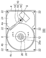
図1は、実施の形態に係る回転機器100を示す図である。図1は、トップカバー(不図示)を外した状態の回転機器100の上面図である。回転機器100は、固定体と、固定体に対して回転する回転体と、回転体に取り付けられる磁気記録ディスク8と、データリード/ライト部10と、を備える。固定体は、ベース4と、ベース4に固定されたシャフト26と、を含む。回転体はハブ28を含む。
以降ベース4に対してハブ28が搭載される側を上側として説明する。
FIG. 1 is a diagram illustrating a rotating device 100 according to an embodiment. FIG. 1 is a top view of the rotating device 100 with a top cover (not shown) removed. The rotating device 100 includes a fixed body, a rotating body that rotates with respect to the fixed body, a magnetic recording disk 8 that is attached to the rotating body, and a data read / write unit 10. The fixed body includes a base 4 and a shaft 26 fixed to the base 4. The rotating body includes a hub 28.
Hereinafter, the side on which the hub 28 is mounted on the base 4 will be described as the upper side.

磁気記録ディスク8は、直径が65mmのガラス製の2.5インチ型磁気記録ディスクであり、その中央の孔の直径は20mm、厚みは0.65mmである。ハブ28は2枚の磁気記録ディスク8を搭載する。
ベース4はアルミニウムの合金をダイカストにより成型して形成される。ベース4は、回転機器100の底部を形成する底板部4aと、磁気記録ディスク8の載置領域を囲むように底板部4aの外周に沿って形成された外周壁部4bと、を有する。
The magnetic recording disk 8 is a glass 2.5-inch magnetic recording disk having a diameter of 65 mm, and the diameter of the hole in the center is 20 mm and the thickness is 0.65 mm. The hub 28 carries two magnetic recording disks 8.
The base 4 is formed by molding an aluminum alloy by die casting. The base 4 includes a bottom plate portion 4a that forms the bottom portion of the rotating device 100, and an outer peripheral wall portion 4b that is formed along the outer periphery of the bottom plate portion 4a so as to surround the mounting area of the magnetic recording disk 8.

データリード/ライト部10は、記録再生ヘッド(不図示)と、スイングアーム14と、ボイスコイルモータ16と、ピボットアセンブリ18と、を含む。記録再生ヘッドは、スイングアーム14の先端部に取り付けられ、磁気記録ディスク8にデータを記録し、磁気記録ディスク8からデータを読み取る。ピボットアセンブリ18は、スイングアーム14をベース4に対してヘッド回転軸Sの周りに揺動自在に支持する。ボイスコイルモータ16は、スイングアーム14をヘッド回転軸Sの周りに揺動させ、記録再生ヘッドを磁気記録ディスク8の上面上の所望の位置に移動させる。ボイスコイルモータ16およびピボットアセンブリ18は、ヘッドの位置を制御する公知の技術を用いて構成される。   The data read / write unit 10 includes a recording / reproducing head (not shown), a swing arm 14, a voice coil motor 16, and a pivot assembly 18. The recording / reproducing head is attached to the tip of the swing arm 14, records data on the magnetic recording disk 8, and reads data from the magnetic recording disk 8. The pivot assembly 18 supports the swing arm 14 so as to be swingable around the head rotation axis S with respect to the base 4. The voice coil motor 16 swings the swing arm 14 around the head rotation axis S and moves the recording / reproducing head to a desired position on the upper surface of the magnetic recording disk 8. The voice coil motor 16 and the pivot assembly 18 are configured using a known technique for controlling the position of the head.

シャフト26の上側の端面にはシャフト固定ねじ穴26aが設けられる。シャフト26の下端はベース4に対して後述のように固定される。シャフト固定ねじ穴26aにトップカバーを貫通してシャフト固定ねじが螺合されることによって、シャフト26の上端はトップカバーに固定される。トップカバーはベース4に固定される。   A shaft fixing screw hole 26 a is provided on the upper end surface of the shaft 26. The lower end of the shaft 26 is fixed to the base 4 as described later. By passing the top cover through the shaft fixing screw hole 26a and screwing the shaft fixing screw, the upper end of the shaft 26 is fixed to the top cover. The top cover is fixed to the base 4.

シャフト固定型の回転機器のなかでもこのようにベース4やトップカバーなどのシャーシにシャフト26の両端が固定されるタイプの回転機器によると、回転機器の耐衝撃性や耐振動性を高めることができる。このタイプの回転機器においては、流体動圧軸受を採用した場合、一般的に潤滑剤の気液界面は2つ存在する。本実施の形態に係る回転機器100では、その2つの気液界面や動圧発生溝を単純に回転軸R方向(回転軸Rに沿った方向)に一列に並べる代わりに、潤滑剤の経路を半径方向に広げるようにして折り返す。これにより、潤滑剤の経路は回転軸R方向において部分的に重複する。そのため、回転機器100の厚さが規定されている場合でも、その厚さ全体に対する動圧発生溝に対応する部分が占める割合を増やすことができる。その結果、動圧発生溝の軸方向寸法である軸受スパンが長くなり軸受の剛性を向上できる。さらに、2つの気液界面間の距離を縮めることができる。その結果、潤滑剤に働く重力や2つの気液界面間の気圧差による潤滑剤の漏れ出しを軽減できる。   Among the fixed shaft type rotating devices, the rotating device in which both ends of the shaft 26 are fixed to the chassis such as the base 4 and the top cover as described above can improve the shock resistance and vibration resistance of the rotating device. it can. In this type of rotating device, when a fluid dynamic pressure bearing is employed, there are generally two gas-liquid interfaces of the lubricant. In the rotating device 100 according to the present embodiment, instead of simply arranging the two gas-liquid interfaces and the dynamic pressure generating grooves in the direction of the rotation axis R (direction along the rotation axis R), the route of the lubricant is changed. Fold it back in the radial direction. As a result, the lubricant paths partially overlap in the direction of the rotation axis R. Therefore, even when the thickness of the rotating device 100 is specified, it is possible to increase the proportion of the portion corresponding to the dynamic pressure generating groove with respect to the entire thickness. As a result, the bearing span, which is the axial dimension of the dynamic pressure generating groove, becomes longer and the rigidity of the bearing can be improved. Further, the distance between the two gas-liquid interfaces can be reduced. As a result, the leakage of the lubricant due to the gravity acting on the lubricant and the pressure difference between the two gas-liquid interfaces can be reduced.

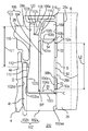
図2は、図1のA−A線断面図である。回転体は、ハブ28と、円筒状マグネット32と、回転体側環囲部材105と、外側環囲部材106と、キャップ12と、を含む。固定体は、ベース4と、積層コア40と、コイル42と、ベース側環囲部材102と、シャフト26と、ハブ側環囲部材108と、を含む。回転体と固定体との隙間の一部に潤滑剤92が連続的に介在する。   2 is a cross-sectional view taken along line AA in FIG. The rotating body includes a hub 28, a cylindrical magnet 32, a rotating body-side surrounding member 105, an outer surrounding member 106, and a cap 12. The fixed body includes a base 4, a laminated core 40, a coil 42, a base-side surrounding member 102, a shaft 26, and a hub-side surrounding member 108. A lubricant 92 is continuously interposed in a part of the gap between the rotating body and the fixed body.

ハブ28のディスク載置面28a上に磁気記録ディスク8が載置される。ハブ28は、軟磁性を有する例えばSUS430F等の鉄鋼材料から形成される。ハブ28は、鉄鋼板を例えばプレス加工や切削加工することにより形成され、回転軸Rに沿って中心孔を有する略カップ状の所定の形状に形成される。ハブ28の鉄鋼材料としては、例えば、大同特殊鋼株式会社が供給する商品名DHS1のステンレスはアウトガスが少なく、加工容易である点で好ましい。また、同様に同社が供給する商品名DHS2のステンレスはさらに耐食性が良好な点でより好ましい。   The magnetic recording disk 8 is mounted on the disk mounting surface 28 a of the hub 28. The hub 28 is made of a steel material such as SUS430F having soft magnetism. The hub 28 is formed by, for example, pressing or cutting a steel plate, and is formed in a predetermined cup-like shape having a center hole along the rotation axis R. As the steel material of the hub 28, for example, stainless steel having a trade name of DHS1 supplied by Daido Steel Co., Ltd. is preferable because it has less outgas and is easy to process. Similarly, stainless steel of the product name DHS2 supplied by the company is more preferable in terms of further excellent corrosion resistance.

円筒状マグネット32は、略カップ形状のハブ28の内側の円筒面に相当する円筒状内周面28fに接着固定される。円筒状マグネット32は、ネオジウム、鉄、ホウ素などを主な材料として形成され、積層コア40の突極と径方向に対向する。円筒状マグネット32にはその周方向に16極の駆動用着磁が施される。円筒状マグネット32の表面には電着塗装やスプレー塗装などによる防錆処理が施される。   The cylindrical magnet 32 is bonded and fixed to a cylindrical inner peripheral surface 28 f corresponding to the cylindrical surface inside the substantially cup-shaped hub 28. The cylindrical magnet 32 is formed using neodymium, iron, boron, or the like as a main material, and faces the salient poles of the laminated core 40 in the radial direction. The cylindrical magnet 32 is magnetized for driving with 16 poles in the circumferential direction. The surface of the cylindrical magnet 32 is rust-proofed by electrodeposition coating or spray coating.

本実施の形態に係る回転機器100においては、円筒状マグネット32の駆動用着磁の回転軸R方向における中心である第1磁気中心62は、積層コア40の回転軸R方向における中心である第2磁気中心64と略一致するように位置する。円筒状マグネット32の駆動用着磁と積層コア40とに起因する回転時の騒音が抑えられる点で好ましい。第1磁気中心62が第2磁気中心64より上方向に離れて位置するようにしてもよい。円筒状マグネット32の軸方向の寸法を大きくすることができるから、円筒状マグネット32に生じる駆動トルクが大きくなる。   In the rotating device 100 according to the present embodiment, the first magnetic center 62 that is the center in the rotation axis R direction of the drive magnetization of the cylindrical magnet 32 is the center in the rotation axis R direction of the laminated core 40. Two magnetic centers 64 are positioned so as to substantially coincide with each other. This is preferable in that noise during rotation caused by the drive magnetization of the cylindrical magnet 32 and the laminated core 40 can be suppressed. The first magnetic center 62 may be located away from the second magnetic center 64 in the upward direction. Since the axial dimension of the cylindrical magnet 32 can be increased, the driving torque generated in the cylindrical magnet 32 is increased.

ハブ28がベース4に対して下向きの状態において、重力によりハブ28が下がり、ベース4から離れ過ぎて正常な回転の妨げとなる可能性がある。この対応ため、ベース4には、円筒状マグネット32の下端に対向する位置に吸引プレート66が接着固定される。吸引プレート66は、例えば鉄を主成分とする材料から形成されて軟磁性を有する。吸引プレート66はマグネット32に磁気的な吸引力を発生する。吸引プレート66は、例えば略リング形状に形成されて、当該リング形状の内周の直径は円筒状マグネット32の内周の直径以上とされてもよい。円筒状マグネット32が発生する磁束のうち積層コア40が受ける割合が増加する。   In a state where the hub 28 is directed downward with respect to the base 4, the hub 28 is lowered by gravity and may be separated from the base 4 and hinder normal rotation. For this purpose, a suction plate 66 is bonded and fixed to the base 4 at a position facing the lower end of the cylindrical magnet 32. The suction plate 66 is made of, for example, a material mainly containing iron and has soft magnetism. The suction plate 66 generates a magnetic attractive force on the magnet 32. The suction plate 66 may be formed in a substantially ring shape, for example, and the inner diameter of the ring shape may be greater than or equal to the inner diameter of the cylindrical magnet 32. The ratio that the laminated core 40 receives in the magnetic flux generated by the cylindrical magnet 32 increases.

回転体側環囲部材105はシャフト26を環囲する円筒状の部材である。回転体側環囲部材105は内周面がシャフト26を環囲する内筒部材104と内筒部材104を環囲する外筒部材103とが別々に形成された後に接着固定されて形成される。内筒部材104の内周面104aには後述するラジアル動圧発生溝が設けられる。内筒部材104の外周には回転軸R方向に沿った溝である連通路BPが設けられる。連通路BPは潤滑剤92が満たされて、後述する経路Aと経路Cとを連通する。連通路BPは経路Aと経路Cの圧力差を小さくすることにより、潤滑剤92の気液界面からの漏れ出しを抑制する。連通路BPは外筒部材103の内周面に軸方向に沿った溝として設けられてもよい。   The rotor-side surrounding member 105 is a cylindrical member that surrounds the shaft 26. The rotary member-side surrounding member 105 is formed by bonding and fixing an inner cylinder member 104 whose inner peripheral surface surrounds the shaft 26 and an outer cylinder member 103 surrounding the inner cylinder member 104 separately. A radial dynamic pressure generating groove, which will be described later, is provided on the inner peripheral surface 104 a of the inner cylinder member 104. A communication path BP that is a groove along the direction of the rotation axis R is provided on the outer periphery of the inner cylinder member 104. The communication path BP is filled with the lubricant 92 and communicates a path A and a path C described later. The communication passage BP suppresses leakage of the lubricant 92 from the gas-liquid interface by reducing the pressure difference between the passage A and the passage C. The communication path BP may be provided as a groove along the axial direction on the inner peripheral surface of the outer cylinder member 103.

積層コア40は円環部とそこから半径方向外側に伸びる12本の突極とを有し、ベース4の上面側に固定される。積層コア40は、5〜10枚の薄型電磁鋼板を積層しカシメにより一体化して形成される。積層コア40の表面には電着塗装や粉体塗装などによる絶縁塗装が施される。積層コア40の各突極にはコイル42が巻回される。このコイル42に3相の略正弦波状の駆動電流が流れることにより突極に沿って駆動磁束が発生する。   The laminated core 40 has an annular portion and twelve salient poles extending radially outward therefrom, and is fixed to the upper surface side of the base 4. The laminated core 40 is formed by laminating 5 to 10 thin electromagnetic steel plates and integrating them by caulking. An insulating coating such as electrodeposition coating or powder coating is applied to the surface of the laminated core 40. A coil 42 is wound around each salient pole of the laminated core 40. When a three-phase substantially sinusoidal drive current flows through the coil 42, a drive magnetic flux is generated along the salient poles.

ベース4には、回転体の回転軸Rを中心とする貫通孔4hが設けられる。ベース側環囲部材102は、シャフト26のベース4側を環囲する円盤部102aと回転体側環囲部材105を環囲する円筒部102bとを有する。つまりベース側環囲部材102は断面が略L字状である。円筒部102bの外周面102bbは貫通孔4hに接着固定される。ベース側環囲部材102は回転体の回転軸Rを中心とするシャフト孔102aaを有し、シャフト26の下側の端部はこのシャフト孔102aaに挿入される。   The base 4 is provided with a through hole 4h centering on the rotation axis R of the rotating body. The base-side surrounding member 102 includes a disk portion 102 a that surrounds the base 4 side of the shaft 26 and a cylindrical portion 102 b that surrounds the rotating body-side surrounding member 105. That is, the base-side surrounding member 102 has a substantially L-shaped cross section. The outer peripheral surface 102bb of the cylindrical portion 102b is bonded and fixed to the through hole 4h. The base-side surrounding member 102 has a shaft hole 102aa centering on the rotation axis R of the rotating body, and the lower end of the shaft 26 is inserted into the shaft hole 102aa.

ベース4は、回転体の回転軸Rを中心とした円筒状の突出部4eを有する。突出部4eは、円筒部102bを環囲するようにベース4の上面から突出する。積層コア40の円環部の中心孔40aが突出部4eの外周面4eaに嵌合されることで積層コア40はベース4に対して固定される。特に積層コア40の円環部は突出部4eに圧入されもしくは隙間ばめによって接着固定される。   The base 4 has a cylindrical protrusion 4e centered on the rotation axis R of the rotating body. The protruding portion 4e protrudes from the upper surface of the base 4 so as to surround the cylindrical portion 102b. The laminated core 40 is fixed to the base 4 by fitting the center hole 40a of the annular portion of the laminated core 40 to the outer peripheral surface 4ea of the protrusion 4e. In particular, the annular portion of the laminated core 40 is press-fitted into the protruding portion 4e or bonded and fixed by a clearance fit.

図3は、図2のうち潤滑剤92の経路の周辺を拡大して示す拡大断面図である。外筒部材103は、外周面103bの回転軸R方向における中間部には半径方向で内側に窪んだ環囲凹部103bbが設けられる。外筒部材103は、外周面103bがハブ28のハブ孔28bに嵌ることによってハブ28に対して固定される。外筒部材103の外周面103bのハブ28側はハブ28のハブ孔28bに接着される。外周面103bのハブ孔28bに固定される部分には周溝が形成される。外周面103bとベース側環囲部材102との隙間として形成される潤滑剤92の経路Dは、内周面104aとシャフト26の側面26bとの隙間として形成される潤滑剤92の経路Bと回転軸R方向で重複する。   FIG. 3 is an enlarged cross-sectional view showing the periphery of the route of the lubricant 92 in FIG. The outer cylinder member 103 is provided with an encircling recess 103bb that is recessed inward in the radial direction at an intermediate portion in the rotation axis R direction of the outer peripheral surface 103b. The outer cylinder member 103 is fixed to the hub 28 by fitting the outer peripheral surface 103 b into the hub hole 28 b of the hub 28. The hub 28 side of the outer peripheral surface 103 b of the outer cylinder member 103 is bonded to the hub hole 28 b of the hub 28. A circumferential groove is formed in a portion of the outer peripheral surface 103b fixed to the hub hole 28b. A route D of the lubricant 92 formed as a gap between the outer peripheral surface 103b and the base-side surrounding member 102 rotates with a route B of the lubricant 92 formed as a gap between the inner peripheral surface 104a and the side surface 26b of the shaft 26. Overlapping in the direction of axis R.

シャフト26の下側の端部は特にベース側環囲部材102の円盤部102aに締まり嵌めによって固定される。この締まり嵌めは例えばシャフト26をシャフト孔102aaに圧入することや、焼き嵌めすることや、シャフト26を液体窒素で冷やした上でシャフト孔102aaに挿入し常温に戻すことなどによって実現される。この締まり嵌めにおいて接着が併用されてもよい。
ベース側環囲部材102は、円筒部102bが貫通孔4hと接する部分の軸方向長さが、円盤部102aがシャフト26と接する部分の軸方向長さより大きい。
The lower end portion of the shaft 26 is fixed to the disk portion 102a of the base-side surrounding member 102 by an interference fit. This interference fit is realized, for example, by press-fitting the shaft 26 into the shaft hole 102aa, shrink fitting, or cooling the shaft 26 with liquid nitrogen and inserting it into the shaft hole 102aa to return to room temperature. Adhesion may be used together in this interference fit.
In the base-side surrounding member 102, the axial length of the portion where the cylindrical portion 102 b contacts the through hole 4 h is larger than the axial length of the portion where the disk portion 102 a contacts the shaft 26.

円筒部102bは円盤部102aと別に形成されて結合されてもよい。本実施の形態のように円筒部102bを円盤部102aと一体に形成すると、部品点数を抑えることができる。円筒部102bの内周面102baと外筒部材103の外周面103bとの隙間は上述の潤滑剤92の経路Dを形成する。内筒部材104の下側の端面である第1スラスト面104dとそれと回転軸R方向で対向するベース側環囲部材102の第1対向面102cとの隙間は、潤滑剤92の経路Cを形成する。第1対向面102cは円盤部102aに設けられる。   The cylindrical part 102b may be formed separately from the disk part 102a. If the cylindrical portion 102b is formed integrally with the disc portion 102a as in the present embodiment, the number of parts can be suppressed. A gap between the inner peripheral surface 102ba of the cylindrical portion 102b and the outer peripheral surface 103b of the outer cylindrical member 103 forms the path D of the lubricant 92 described above. A gap between the first thrust surface 104d, which is the lower end surface of the inner cylinder member 104, and the first opposing surface 102c of the base-side surrounding member 102 that opposes it in the direction of the rotation axis R forms a path C of the lubricant 92. To do. The first facing surface 102c is provided on the disk portion 102a.

円筒部102bの内周面102baと外筒部材103の外周面103bとの間の隙間が上方に向けて徐々に広がる部分である第1キャピラリーシール110が形成される。第1キャピラリーシール110は潤滑剤92の第1気液界面112を有し、毛細管現象により潤滑剤92の漏れ出しを抑止する。潤滑剤92の第1気液界面112は、円筒部102bの内周面102baと外筒部材103の外周面103bとに接している。潤滑剤92の漏れ出しをさらに抑えるため、第1キャピラリーシール110はその出口付近に撥油剤が塗布された領域を有してもよい。   A first capillary seal 110 is formed, which is a portion where the gap between the inner peripheral surface 102ba of the cylindrical portion 102b and the outer peripheral surface 103b of the outer cylindrical member 103 gradually widens upward. The first capillary seal 110 has a first gas-liquid interface 112 of the lubricant 92 and suppresses leakage of the lubricant 92 due to capillary action. The first gas-liquid interface 112 of the lubricant 92 is in contact with the inner peripheral surface 102ba of the cylindrical portion 102b and the outer peripheral surface 103b of the outer cylindrical member 103. In order to further suppress the leakage of the lubricant 92, the first capillary seal 110 may have a region where an oil repellent is applied in the vicinity of the outlet.

例えば回転機器が衝撃を受けた場合に、第1気液界面112から潤滑剤92が飛散することがある。これに対応して、第1気液界面112と回転軸R方向に対向する位置に開口を有する袋状の空間である溜まり部115が設けられる。第1気液界面112から飛散した潤滑剤92は溜まり部115に捕えられ、外部への漏れ出しが抑制される。溜まり部115はハブ28と外筒部材103との間に形成される。具体的には、ハブ孔28bと外周面103bとの間の隙間に形成される。溜まり部115には撥油剤が塗布されてもよい。潤滑剤92の漏れ出しが一層抑えられる。溜まり部115は、ハブ孔28bと環囲凹部103bbとの隙間が下方に向けて徐々に広がる部分に設けられてもよい。環囲凹部103bbの凹みにより溜まり部115の空間の容積が大きくなり、多くの潤滑剤92が飛散した場合にも外部への漏れ出しを抑えうる。   For example, when the rotating device receives an impact, the lubricant 92 may scatter from the first gas-liquid interface 112. Correspondingly, a reservoir 115 which is a bag-like space having an opening at a position facing the first gas-liquid interface 112 in the direction of the rotation axis R is provided. The lubricant 92 scattered from the first gas-liquid interface 112 is caught by the pool portion 115, and leakage to the outside is suppressed. The reservoir 115 is formed between the hub 28 and the outer cylinder member 103. Specifically, it is formed in a gap between the hub hole 28b and the outer peripheral surface 103b. The reservoir 115 may be coated with an oil repellent. Leakage of the lubricant 92 is further suppressed. The reservoir 115 may be provided in a portion where the gap between the hub hole 28b and the surrounding recess 103bb gradually expands downward. The volume of the reservoir 115 is increased by the recess of the surrounding recess 103bb, and leakage to the outside can be suppressed even when a large amount of the lubricant 92 is scattered.

ハブ側環囲部材108は、シャフト26の上側を環囲してシャフト26に固定される。ハブ側環囲部材108は回転体の回転軸Rを中心とする略円環状の部材であり、その中心孔108aにシャフト26が挿入される。ハブ側環囲部材108はシャフト26の上側で締まり嵌めによってシャフト26に対して固定されている。   The hub-side surrounding member 108 surrounds the upper side of the shaft 26 and is fixed to the shaft 26. The hub-side surrounding member 108 is a substantially annular member centered on the rotation axis R of the rotating body, and the shaft 26 is inserted into the center hole 108a thereof. The hub-side surrounding member 108 is fixed to the shaft 26 by an interference fit on the upper side of the shaft 26.

外側環囲部材106は、ハブ側環囲部材108を環囲して外筒部材103に固定される円筒状の部材である。外側環囲部材106は、外筒部材103の内周面の上側に設けられた段部103cに接着剤120によって接着固定される。接着剤120は外側環囲部材106と外筒部材103に亘って塗布される。圧入など他の既知の方法により固定されてもよい。外側環囲部材106とハブ側環囲部材108との間には、外側環囲部材106の内周面106aとハブ側環囲部材108の外周面108bとの間の隙間が上方に向けて徐々に広がる部分である第2キャピラリーシール114が形成される。第2キャピラリーシール114は潤滑剤92の第2気液界面116を有し、毛細管現象により潤滑剤92の漏れ出しを抑止する。潤滑剤92の第2気液界面116は、外側環囲部材106の内周面106aとハブ側環囲部材108の外周面108bとに接している。潤滑剤92の漏れ出しをさらに抑えるため、第2キャピラリーシール114はその出口付近に撥油剤が塗布された領域を有してもよい。   The outer surrounding member 106 is a cylindrical member that surrounds the hub-side surrounding member 108 and is fixed to the outer cylinder member 103. The outer surrounding member 106 is bonded and fixed to the stepped portion 103 c provided on the upper side of the inner peripheral surface of the outer cylinder member 103 with an adhesive 120. The adhesive 120 is applied across the outer surrounding member 106 and the outer cylinder member 103. It may be fixed by other known methods such as press fitting. Between the outer surrounding member 106 and the hub-side surrounding member 108, a gap between the inner peripheral surface 106a of the outer surrounding member 106 and the outer peripheral surface 108b of the hub-side surrounding member 108 gradually increases upward. A second capillary seal 114, which is a portion that extends in the range, is formed. The second capillary seal 114 has a second gas-liquid interface 116 of the lubricant 92 and suppresses the leakage of the lubricant 92 due to capillary action. The second gas-liquid interface 116 of the lubricant 92 is in contact with the inner peripheral surface 106 a of the outer surrounding member 106 and the outer peripheral surface 108 b of the hub side surrounding member 108. In order to further suppress leakage of the lubricant 92, the second capillary seal 114 may have a region where an oil repellent is applied in the vicinity of the outlet thereof.

内筒部材104の上側の第2スラスト面104eとそれと回転軸R方向で対向するハブ側環囲部材108の第2対向面108cとの隙間は、潤滑剤92の経路Aを形成する。第2対向面108cは前記ハブ側環囲部材108に設けられる。
キャップ12は円盤状の環状部材で、外周面がハブ28のハブ孔28bに固定される。キャップ12は、第2気液界面116とハブ側環囲部材108とを覆うように設けられる。キャップ12の下側の端面は外筒部材103の上側の端面に接している。
A gap between the second thrust surface 104e on the upper side of the inner cylinder member 104 and the second facing surface 108c of the hub-side surrounding member 108 facing it in the direction of the rotation axis R forms a path A of the lubricant 92. The second facing surface 108c is provided on the hub-side surrounding member 108.
The cap 12 is a disc-shaped annular member, and the outer peripheral surface is fixed to the hub hole 28 b of the hub 28. The cap 12 is provided so as to cover the second gas-liquid interface 116 and the hub-side surrounding member 108. The lower end surface of the cap 12 is in contact with the upper end surface of the outer cylinder member 103.

内筒部材104の内周面104aには、回転軸R方向に離間した1組のヘリングボーン形状の第1ラジアル動圧発生溝50、第2ラジアル動圧発生溝52が形成される。第2ラジアル動圧発生溝52は第1ラジアル動圧発生溝50の上側に形成される。なお、第1ラジアル動圧発生溝50および第2ラジアル動圧発生溝52のうちの少なくともひとつは、内周面104aの代わりにシャフト26の側面26bに形成されてもよい。   A set of herringbone-shaped first radial dynamic pressure generating grooves 50 and second radial dynamic pressure generating grooves 52 spaced apart in the direction of the rotation axis R are formed on the inner peripheral surface 104a of the inner cylinder member 104. The second radial dynamic pressure generating groove 52 is formed above the first radial dynamic pressure generating groove 50. Note that at least one of the first radial dynamic pressure generating groove 50 and the second radial dynamic pressure generating groove 52 may be formed on the side surface 26b of the shaft 26 instead of the inner peripheral surface 104a.

潤滑剤92の経路Bは、内筒部材104の内周面104aのうち第1ラジアル動圧発生溝50が形成される部分とシャフト26の側面26bとの隙間、および回転体側環囲部材105の内周面104aのうち第2ラジアル動圧発生溝52が形成される部分とシャフト26の側面26bとの隙間を含む。
回転体が固定体に対して相対的に回転するとき、第1ラジアル動圧発生溝50、第2ラジアル動圧発生溝52はそれぞれ隙間内の潤滑剤92に動圧を生じさせる。この動圧によって回転体は、固定体と非接触のまま半径方向に支持される。
A path B of the lubricant 92 is formed between the portion of the inner peripheral surface 104 a of the inner cylinder member 104 where the first radial dynamic pressure generating groove 50 is formed and the side surface 26 b of the shaft 26, and the rotating body side surrounding member 105. It includes a gap between a portion of the inner peripheral surface 104 a where the second radial dynamic pressure generating groove 52 is formed and the side surface 26 b of the shaft 26.
When the rotating body rotates relative to the fixed body, the first radial dynamic pressure generating groove 50 and the second radial dynamic pressure generating groove 52 respectively generate dynamic pressure in the lubricant 92 in the gap. With this dynamic pressure, the rotating body is supported in the radial direction without contacting the fixed body.

内筒部材104の下側の第1スラスト面104dには、ヘリングボーン形状またはスパイラル形状の第1スラスト動圧発生溝56が形成される。第1スラスト動圧発生溝56は、第1スラスト面104dの代わりにベース側環囲部材102の第1対向面102cに形成されてもよい。
内筒部材104の上側の第2スラスト面104eには、ヘリングボーン形状またはスパイラル形状の第2スラスト動圧発生溝54が形成される。第2スラスト動圧発生溝54は、第2スラスト面104eの代わりにハブ側環囲部材108の第2対向面108cに形成されてもよい。
A first thrust dynamic pressure generating groove 56 having a herringbone shape or a spiral shape is formed on the lower first thrust surface 104d of the inner cylinder member 104. The first thrust dynamic pressure generating groove 56 may be formed on the first facing surface 102c of the base-side surrounding member 102 instead of the first thrust surface 104d.
A second thrust dynamic pressure generating groove 54 having a herringbone shape or a spiral shape is formed on the second thrust surface 104e on the upper side of the inner cylinder member 104. The second thrust dynamic pressure generating groove 54 may be formed on the second facing surface 108c of the hub-side surrounding member 108 instead of the second thrust surface 104e.

潤滑剤92の経路Cは、内筒部材104の下側の第1スラスト面104dのうち第1スラスト動圧発生溝56が形成される部分とベース側環囲部材102の第1対向面102cとの隙間を含む。
潤滑剤92の経路Aは、内筒部材104の上側の第2スラスト面104eのうち第2スラスト動圧発生溝54が形成される部分とハブ側環囲部材108の第2対向面108cとの隙間を含む。
回転体が固定体に対して相対的に回転するとき、第2スラスト動圧発生溝54、第1スラスト動圧発生溝56はそれぞれ隙間内の潤滑剤92に動圧を生じさせる。この動圧によって回転体は、固定体と非接触のまま回転軸R方向に支持される。
The path C of the lubricant 92 includes a portion of the first thrust surface 104d on the lower side of the inner cylinder member 104 where the first thrust dynamic pressure generating groove 56 is formed and the first facing surface 102c of the base-side surrounding member 102. Including gaps.
The path A of the lubricant 92 is formed between the portion of the second thrust surface 104e on the upper side of the inner cylinder member 104 where the second thrust dynamic pressure generating groove 54 is formed and the second facing surface 108c of the hub-side surrounding member 108. Including gaps.
When the rotating body rotates relative to the fixed body, the second thrust dynamic pressure generating groove 54 and the first thrust dynamic pressure generating groove 56 each generate dynamic pressure in the lubricant 92 in the gap. With this dynamic pressure, the rotating body is supported in the direction of the rotation axis R without contacting the fixed body.

潤滑剤92の第1気液界面112と第2気液界面116との回転軸R方向における距離L1は、第1ラジアル動圧発生溝50の第2ラジアル動圧発生溝52とは反対側の端部50aから第2ラジアル動圧発生溝52の第1ラジアル動圧発生溝50とは反対側の端部52aまでの距離L2よりも小さい。   A distance L1 between the first gas-liquid interface 112 and the second gas-liquid interface 116 in the rotation axis R direction of the lubricant 92 is on the opposite side of the first radial dynamic pressure generating groove 50 from the second radial dynamic pressure generating groove 52. The distance L2 is smaller than the distance L2 from the end 50a to the end 52a of the second radial dynamic pressure generating groove 52 opposite to the first radial dynamic pressure generating groove 50.

潤滑剤92は、第1気液界面112から経路D、経路C、経路B、経路Aをこの順に経て第2気液界面116に至るまで連続的に存在する。動圧発生溝の観点からは、潤滑剤92は第1気液界面112から第1スラスト動圧発生溝56、第1ラジアル動圧発生溝50、第2ラジアル動圧発生溝52、第2スラスト動圧発生溝54をこの順に経て第2気液界面116に至るまで連続的に存在する。   The lubricant 92 continuously exists from the first gas-liquid interface 112 to the second gas-liquid interface 116 through the path D, the path C, the path B, and the path A in this order. From the viewpoint of the dynamic pressure generating groove, the lubricant 92 is transferred from the first gas-liquid interface 112 to the first thrust dynamic pressure generating groove 56, the first radial dynamic pressure generating groove 50, the second radial dynamic pressure generating groove 52, and the second thrust. It exists continuously through the dynamic pressure generating groove 54 to the second gas-liquid interface 116 in this order.

第1気液界面112は、回転軸R方向において第1ラジアル動圧発生溝50の第2ラジアル動圧発生溝52側の端部50bよりも第2ラジアル動圧発生溝52側に位置する。特に第1気液界面112は、回転軸R方向において第1ラジアル動圧発生溝50と第2ラジアル動圧発生溝52との間に位置する。   The first gas-liquid interface 112 is located closer to the second radial dynamic pressure generating groove 52 side than the end 50b of the first radial dynamic pressure generating groove 50 on the second radial dynamic pressure generating groove 52 side in the direction of the rotation axis R. In particular, the first gas-liquid interface 112 is located between the first radial dynamic pressure generating groove 50 and the second radial dynamic pressure generating groove 52 in the rotation axis R direction.

以上のように構成された回転機器100の動作を説明する。磁気記録ディスク8を回転させるために、3相の駆動電流がコイル42に供給される。その駆動電流がコイル42を流れることにより、12本の突極に沿って磁束が発生する。この磁束によって円筒状マグネット32に駆動トルクが与えられ、回転体およびそれに嵌合された磁気記録ディスク8が回転する。同時にボイスコイルモータ16がスイングアーム14を揺動させることによって、記録再生ヘッドが磁気記録ディスク8上の揺動範囲を行き来する。記録再生ヘッドは磁気記録ディスク8に記録された磁気データを電気信号に変換して制御基板(不図示)へ伝え、また制御基板から電気信号の形で送られてくるデータを磁気記録ディスク8上に磁気データとして書き込む。   The operation of the rotating device 100 configured as described above will be described. In order to rotate the magnetic recording disk 8, a three-phase drive current is supplied to the coil 42. When the drive current flows through the coil 42, magnetic flux is generated along the 12 salient poles. A driving torque is applied to the cylindrical magnet 32 by this magnetic flux, and the rotating body and the magnetic recording disk 8 fitted thereto rotate. At the same time, the voice coil motor 16 swings the swing arm 14, so that the recording / reproducing head moves back and forth on the magnetic recording disk 8. The recording / reproducing head converts the magnetic data recorded on the magnetic recording disk 8 into an electric signal and transmits it to a control board (not shown), and the data sent from the control board in the form of an electric signal is recorded on the magnetic recording disk 8. Is written as magnetic data.

本実施の形態に係る回転機器100では、第1ラジアル動圧発生溝50と第2ラジアル動圧発生溝52とを回転軸R方向でより離すことができる。これにより、軸受の剛性をより高めることができる。また、距離L1は距離L2よりも小さい。したがって、第1気液界面112と第2気液界面116とを回転軸R方向でより近づけることができる。これにより、潤滑剤92に働く重力や第1気液界面112での気圧と第2気液界面116での気圧との気圧差による潤滑剤92の漏れ出しを軽減できる。   In the rotating device 100 according to the present embodiment, the first radial dynamic pressure generating groove 50 and the second radial dynamic pressure generating groove 52 can be further separated in the direction of the rotation axis R. Thereby, the rigidity of a bearing can be raised more. The distance L1 is smaller than the distance L2. Therefore, the first gas-liquid interface 112 and the second gas-liquid interface 116 can be made closer in the direction of the rotation axis R. Thereby, the leakage of the lubricant 92 due to the gravity acting on the lubricant 92 and the pressure difference between the air pressure at the first gas-liquid interface 112 and the air pressure at the second gas-liquid interface 116 can be reduced.

シャフト固定型の回転機器におけるシャフトとベースとの接合部分について、シャフトのベースに対する直角度を調整できるようシャフトを接着により固定することが望ましい。しかしながら特にシャフトの径が小さい場合は、接着では接合の強度が十分に得られない場合も生じうる。   It is desirable to fix the shaft by bonding so that the perpendicularity of the shaft with respect to the base of the joint portion between the shaft and the base in the fixed shaft type rotating device can be adjusted. However, particularly when the diameter of the shaft is small, there may be a case where sufficient bonding strength cannot be obtained by bonding.

本実施の形態に係る回転機器100では、ベース側環囲部材102の内周側にシャフト26を締まり嵌めし、外周側をベース4に接着する。これにより、ベース側環囲部材102の外周側をベース4に接着する際に、シャフト26のベース4に対する直角度を適正に保ちつつ接着剤を硬化させることができる。また強度面については、シャフト26とベース側環囲部材102とは締まり嵌めなのでその接合の強度は十分であり、かつ、シャフト26の径に比べてベース側環囲部材102の外周面の径は大きいのでベース側環囲部材102とベース4との接着による接合の強度もまた十分となりうる。   In the rotating device 100 according to the present embodiment, the shaft 26 is tightly fitted on the inner peripheral side of the base-side surrounding member 102, and the outer peripheral side is bonded to the base 4. Thereby, when the outer peripheral side of the base-side surrounding member 102 is bonded to the base 4, the adhesive can be cured while keeping the perpendicularity of the shaft 26 to the base 4 proper. As for the strength surface, since the shaft 26 and the base-side surrounding member 102 are tightly fitted, the strength of the joint is sufficient, and the diameter of the outer peripheral surface of the base-side surrounding member 102 is larger than the diameter of the shaft 26. Since it is large, the strength of joining by bonding the base side surrounding member 102 and the base 4 can also be sufficient.

次に、実施の形態に係る回転機器100の製造方法について説明する。
まず、シャフト26にベース側環囲部材102が結合される。また内周面104a、第1スラスト面104d及び第2スラスト面104eに所定の動圧発生溝が形成された内筒部材104と外筒部材103とが結合される。次に、内筒部材104の内周面104aにシャフト26が挿入される。次に、シャフト26の上側にハブ側環囲部材108が所定の位置に結合される。外筒部材103の段部103cに外側環囲部材106が結合される。以下、この状態を軸受アッセンブリと言う。次に、軸受アッセンブリを減圧環境下に晒して、固定体と回転体の隙間の空気が抜かれる。また減圧環境下において、外側環囲部材106とハブ側環囲部材108の隙間及び、ベース側環囲部材102と外筒部材103の隙間に、所定の量の潤滑剤92が付着される。例えば、接近させた注液ノズルから潤滑剤92を吐出して付着させできる。次に、軸受アッセンブリを大気圧下に戻して、潤滑剤92を軸受アッセンブリの内部に浸透させる。この結果、潤滑剤92は固定体と回転体の隙間に浸透して介在する。
Next, a method for manufacturing the rotating device 100 according to the embodiment will be described.
First, the base-side surrounding member 102 is coupled to the shaft 26. Further, the inner cylinder member 104 and the outer cylinder member 103 in which predetermined dynamic pressure generating grooves are formed on the inner peripheral surface 104a, the first thrust surface 104d, and the second thrust surface 104e are coupled. Next, the shaft 26 is inserted into the inner peripheral surface 104 a of the inner cylinder member 104. Next, the hub-side surrounding member 108 is coupled to a predetermined position on the upper side of the shaft 26. The outer surrounding member 106 is coupled to the step portion 103 c of the outer cylinder member 103. Hereinafter, this state is referred to as a bearing assembly. Next, the bearing assembly is exposed to a reduced pressure environment, and the air in the gap between the fixed body and the rotating body is removed. In a reduced pressure environment, a predetermined amount of lubricant 92 is attached to the gap between the outer surrounding member 106 and the hub side surrounding member 108 and the gap between the base side surrounding member 102 and the outer cylinder member 103. For example, the lubricant 92 can be discharged and adhered from a liquid injection nozzle that has been approached. Next, the bearing assembly is returned to atmospheric pressure to allow the lubricant 92 to penetrate into the bearing assembly. As a result, the lubricant 92 penetrates into the gap between the fixed body and the rotating body.

次に、軸受アッセンブリの第1気液界面112と第2気液界面116の回転軸R方向における位置が検査される。気液界面の位置は、レーザー光線を気液界面に照射してその反射光に応じて検査することができる。実施の形態に係る回転機器100においては、軸受アッセンブリの状態では、第1気液界面112と第2気液界面116とは同一の方向から目視できる。したがって、第1気液界面112と第2気液界面116の位置は同一の方向からレーザー光線を照射して検査できる。このため、軸受アッセンブリを反転させて検査する必要がなく、検査装置が小型になり検査の手間も少なくなる。   Next, the positions of the first gas-liquid interface 112 and the second gas-liquid interface 116 of the bearing assembly in the direction of the rotation axis R are inspected. The position of the gas-liquid interface can be inspected according to the reflected light by irradiating the gas-liquid interface with a laser beam. In the rotating device 100 according to the embodiment, the first gas-liquid interface 112 and the second gas-liquid interface 116 can be viewed from the same direction in the state of the bearing assembly. Therefore, the positions of the first gas-liquid interface 112 and the second gas-liquid interface 116 can be inspected by irradiating a laser beam from the same direction. For this reason, it is not necessary to invert the bearing assembly for inspection, and the inspection apparatus becomes smaller and the labor for inspection is reduced.

一方で略カップ形状のハブ28の円筒状内周面28fに円筒状マグネット32が接着固定される。また、コイル42を伴った積層コア40がベース4の外周面4eaに接着固定される。   On the other hand, the cylindrical magnet 32 is bonded and fixed to the cylindrical inner peripheral surface 28f of the substantially cup-shaped hub 28. Further, the laminated core 40 with the coil 42 is bonded and fixed to the outer peripheral surface 4ea of the base 4.

次に、回転体側環囲部材105の外筒部材103の外周面103bがハブ26のハブ孔26bに接着固定される。次に、固定体側環囲部材102の外周面102bbが貫通孔4hに接着固定される。この際に、ベース4に対するハブ28のディスク載置面28aの傾きを適正に保ちつつ接着剤を硬化させる。この結果、ハブ28のディスク載置面28aのベース4に対する傾きが抑えられる。   Next, the outer peripheral surface 103 b of the outer cylinder member 103 of the rotating body side surrounding member 105 is bonded and fixed to the hub hole 26 b of the hub 26. Next, the outer peripheral surface 102bb of the fixed body side surrounding member 102 is bonded and fixed to the through hole 4h. At this time, the adhesive is cured while keeping the inclination of the disk mounting surface 28a of the hub 28 with respect to the base 4 appropriate. As a result, the inclination of the disk mounting surface 28a of the hub 28 with respect to the base 4 is suppressed.

次に、その他の部材が搭載され、所定の検査が行われて回転機器100が製造される。   Next, other members are mounted, a predetermined inspection is performed, and the rotating device 100 is manufactured.

以上、実施の形態に係る回転機器100の構成と動作について説明した。これらの実施の形態は例示であり、それらの各構成要素の組み合わせにいろいろな変形例が可能なこと、またそうした変形例も本発明の範囲にあることは当業者に理解されるところである。   The configuration and operation of the rotating device 100 according to the embodiment have been described above. It is to be understood by those skilled in the art that these embodiments are exemplifications, and that various modifications can be made to combinations of the respective components, and such modifications are within the scope of the present invention.

図4は、本実施の形態に係る回転機器の変形例200について潤滑剤の経路の周辺を拡大して示す拡大断面図である。変形例200においては、外筒部材103のハブ孔28bと接する部分の直径が第1気液界面112の最内周部の直径より小さく形成されている。
つまり第1気液界面112の最内周部が外筒部材103のハブ孔28bに接する部分の最外周部より半径方向外側に位置する。この結果、ハブ28が外筒部材103に固定される前は、第1気液界面112は上方から容易に目視しうる。潤滑剤92が不足しているか否かを検査する場合は、容易に確認しうるから検査の手間が少なくなる。また、レーザー光線を照射して第1気液界面112の軸方向の位置を検査する場合は、レーザー光線の位置合わせが容易になるから検査の手間が少なくなる。
FIG. 4 is an enlarged cross-sectional view showing the periphery of the lubricant path in an enlarged manner in the modified example 200 of the rotating device according to the present embodiment. In the modified example 200, the diameter of the portion of the outer cylinder member 103 that contacts the hub hole 28b is smaller than the diameter of the innermost peripheral portion of the first gas-liquid interface 112.
That is, the innermost peripheral portion of the first gas-liquid interface 112 is positioned radially outward from the outermost peripheral portion of the portion in contact with the hub hole 28 b of the outer cylinder member 103. As a result, before the hub 28 is fixed to the outer cylinder member 103, the first gas-liquid interface 112 can be easily seen from above. In the case of inspecting whether or not the lubricant 92 is insufficient, since it can be easily confirmed, the labor of the inspection is reduced. Further, when the position of the first gas-liquid interface 112 in the axial direction is inspected by irradiating a laser beam, the alignment of the laser beam is facilitated, and the labor of the inspection is reduced.

また、回転軸R方向において外側環囲部材106の上端が外筒部材103の上端より上側に位置する。この結果、外筒部材103と外側環囲部材106とに亘って塗布した接着剤120が外側環囲部材106の上端を越えてキャピラリーシール114に流れ込む可能性が軽減される。接着剤120は外側環囲部材106と外筒部材103とハブ28に亘って塗布するようにしてもよい。   Further, the upper end of the outer surrounding member 106 is positioned above the upper end of the outer cylinder member 103 in the direction of the rotation axis R. As a result, the possibility that the adhesive 120 applied across the outer cylinder member 103 and the outer surrounding member 106 flows into the capillary seal 114 beyond the upper end of the outer surrounding member 106 is reduced. The adhesive 120 may be applied over the outer surrounding member 106, the outer cylinder member 103, and the hub 28.

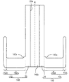
実施の形態及び変形例では、シャフト26がベース側環囲部材102とは別々に形成される場合について説明したが、これに限られない。図5は、図4の変形例200についてシャフト26がベース側環囲部材102と一体に形成されたベース側部材140を示す拡大断面図である。部品点数が少なくなるから組み立ての手間が少なくなる。また回転機器が薄く形成される場合にもシャフト26とベース側環囲部材102との接合強度を高く保つことができる。   In the embodiment and the modification, the case where the shaft 26 is formed separately from the base-side surrounding member 102 has been described, but the present invention is not limited to this. FIG. 5 is an enlarged cross-sectional view showing the base-side member 140 in which the shaft 26 is formed integrally with the base-side surrounding member 102 in the modification 200 of FIG. Since the number of parts is reduced, the assembly work is reduced. Even when the rotating device is formed thin, the bonding strength between the shaft 26 and the base-side surrounding member 102 can be kept high.

図5の例において、ベース側部材140はJIS名SUS430相当のステンレス材料からプレス加工によって一体に形成された後、切削加工や研削加工によって細部が仕上られる。ベース側部材140は所望の仕様を満足するように別の材料又は別の製造方法によって形成されてもよい。シャフト26にはプレス加工によって貫通孔140bが設けられる。貫通孔140bの上端側にはシャフト固定ねじ穴26aが形成される。シャフト26とベース側環囲部材102との接続部分に直径を拡大する突条部140aが形成される。回転機器200が衝撃を受けた場合に当該接続部分の変形を抑制しうる。   In the example of FIG. 5, the base side member 140 is integrally formed by press working from a stainless material corresponding to JIS name SUS430, and then the details are finished by cutting or grinding. The base side member 140 may be formed of another material or another manufacturing method so as to satisfy a desired specification. The shaft 26 is provided with a through hole 140b by pressing. A shaft fixing screw hole 26a is formed on the upper end side of the through hole 140b. A protruding portion 140 a that expands the diameter is formed at a connection portion between the shaft 26 and the base-side surrounding member 102. When the rotating device 200 receives an impact, deformation of the connection portion can be suppressed.

実施の形態及び変形例では、外側環囲部材106は、外筒部材103の内周面に固定される場合に付いて説明したが、これに限られない。たとえばハブ28に固定されてもよい。   In the embodiment and the modification, the outer surrounding member 106 is described as being fixed to the inner peripheral surface of the outer cylinder member 103, but the present invention is not limited to this. For example, it may be fixed to the hub 28.

実施の形態及び変形例では、回転体側環囲部材105は、内筒部材104と外筒部材103とを別々に形成して結合する場合について説明したが、これに限られない。たとえば内筒部材104と外筒部材103とは、一体に形成されてもよい。   In the embodiment and the modification, the rotating body side surrounding member 105 has been described with respect to the case where the inner cylinder member 104 and the outer cylinder member 103 are separately formed and coupled, but the present invention is not limited thereto. For example, the inner cylinder member 104 and the outer cylinder member 103 may be integrally formed.

実施の形態及び変形例では、ハブ28と回転体側環囲部材105とを結合する場合について説明したが、これに限られない。たとえばハブ28と回転体側環囲部材105とは、一体に形成されてもよい。この場合、ハブ28の外周面28gと内周面104aとは、連続して切削加工が施されてもよい。ハブ28の外周面28gの中心と回転体側環囲部材105の内周面104aの中心との不一致を抑えやすい。   In the embodiment and the modification, the case where the hub 28 and the rotating body side surrounding member 105 are coupled has been described, but the present invention is not limited to this. For example, the hub 28 and the rotating body side surrounding member 105 may be integrally formed. In this case, the outer peripheral surface 28g and the inner peripheral surface 104a of the hub 28 may be continuously cut. It is easy to suppress a mismatch between the center of the outer peripheral surface 28 g of the hub 28 and the center of the inner peripheral surface 104 a of the rotating body side surrounding member 105.

実施の形態及び変形例では、円筒状マグネット32が積層コア40の外側に位置する、いわゆるアウターロータ型の場合について説明したが、これに限られない。たとえば円筒状マグネットが積層コアの内側に位置する、いわゆるインナーロータ型であってもよい。   In the embodiment and the modification, the case of the so-called outer rotor type in which the cylindrical magnet 32 is located outside the laminated core 40 has been described, but the present invention is not limited to this. For example, a so-called inner rotor type in which a cylindrical magnet is positioned inside a laminated core may be used.

実施の形態及び変形例では積層コアを用いる場合について説明したが、コアは積層コアでなくてもよい。   Although the case where a laminated core is used has been described in the embodiment and the modification, the core may not be a laminated core.

4 ベース、 8 磁気記録ディスク、 10 データリード/ライト部、 12 キャップ、 26 シャフト、 28 ハブ、 32 円筒状マグネット、 40 積層コア、 42 コイル、 50 第1ラジアル動圧発生溝、 52 第2ラジアル動圧発生溝、 54 第2スラスト動圧発生溝、 56 第1スラスト動圧発生溝、 62 第1磁気中心、 64 第2磁気中心、 66 吸引プレート、 92 潤滑剤、 100 回転機器、 102 ベース側環囲部材、103 外筒部材、 104 内筒部材、 105 回転体側環囲部材、 106 外側環囲部材、 108 ハブ側環囲部材、 112 第1気液界面、116 第2気液界面、 110 第1キャピラリーシール、114 第2キャピラリーシール、120 接着剤、BP 連通路、140 ベース側部材、 100、200 回転機器。   4 base, 8 magnetic recording disk, 10 data read / write section, 12 cap, 26 shaft, 28 hub, 32 cylindrical magnet, 40 laminated core, 42 coil, 50 first radial dynamic pressure generating groove, 52 second radial motion Pressure generating groove, 54 second thrust dynamic pressure generating groove, 56 first thrust dynamic pressure generating groove, 62 first magnetic center, 64 second magnetic center, 66 suction plate, 92 lubricant, 100 rotating device, 102 base side ring Enclosing member, 103 Outer cylinder member, 104 Inner cylinder member, 105 Rotating body side surrounding member, 106 Outer surrounding member, 108 Hub side surrounding member, 112 First gas-liquid interface, 116 Second gas-liquid interface, 110 First Capillary seal, 114 Second capillary seal, 120 Adhesive, BP communication path, 140 Over scan side member, 100, 200 rotating device.

Claims (11)

ベースと前記ベースに固定されたシャフトとを有する固定体と、
記録ディスクが載置されるべきハブと、前記ハブに設けられたハブ孔に固定され、前記シャフトを環囲する回転体側環囲部材とを有する回転体と、を備え、
前記固定体と前記回転体とに潤滑剤が連続的に介在し、
前記潤滑剤は少なくとも第1気液界面と第2気液界面とを有し、
前記回転体側環囲部材と前記シャフトの前記潤滑剤が接する面のいずれかにはラジアル動圧を発生するラジアル動圧発生溝が形成され、
前記固定体は、前記シャフトの前記ベース側を環囲する円盤部と前記回転体側環囲部材を環囲する円筒部を有するベース側環囲部材を含み、
前記ベース側環囲部材は、前記円盤部が前記シャフトの前記ベース側に締り嵌めにより固定されるとともに、前記円筒部が前記ベースに設けられた貫通孔に接着固定され、
前記第1気液界面は前記円筒部の内周面と前記回転体側環囲部材の外周面の半径方向隙間に位置することを特徴とする回転機器。
A fixed body having a base and a shaft fixed to the base;
A rotating body having a hub on which a recording disk is to be placed, and a rotating body-side surrounding member fixed to a hub hole provided in the hub and surrounding the shaft;
A lubricant is continuously interposed between the fixed body and the rotating body,
The lubricant has at least a first gas-liquid interface and a second gas-liquid interface;
A radial dynamic pressure generating groove for generating a radial dynamic pressure is formed on any of the surfaces of the rotating body side surrounding member and the shaft that are in contact with the lubricant,
The fixed body includes a base side surrounding member having a disk portion surrounding the base side of the shaft and a cylindrical portion surrounding the rotating body side surrounding member,
The base-side surrounding member has the disk portion fixed to the base side of the shaft by an interference fit, and the cylindrical portion is adhesively fixed to a through-hole provided in the base.
The rotary device according to claim 1, wherein the first gas-liquid interface is located in a radial gap between an inner peripheral surface of the cylindrical portion and an outer peripheral surface of the rotating body side surrounding member.
前記固定体は、前記シャフトの前記ハブ側を環囲して前記シャフトに固定されたハブ側環囲部材を含み、前記第2気液界面は、前記回転体と前記ハブ側環囲部材の外周面との半径方向隙間に位置することを特徴とする請求項1に記載の回転機器。   The fixed body includes a hub-side surrounding member that surrounds the hub side of the shaft and is fixed to the shaft, and the second gas-liquid interface is an outer periphery of the rotating body and the hub-side surrounding member. The rotating device according to claim 1, wherein the rotating device is located in a radial gap with the surface. 前記回転体側環囲部材は、前記回転体側環囲部材の前記ベース側の面である第1スラスト面と、前記ベースと反対側の面である第2スラスト面と、を有し、
前記固定体は、前記第1スラスト面とスラスト方向に対向する第1対向面と、前記第2スラスト面とスラスト方向に対向する第2対向面と、を有し、
前記第1スラスト面と前記第1対向面のいずれかにはスラスト方向の動圧を発生する第1スラスト動圧溝が形成され、
前記第2スラスト面と前記第2対向面のいずれかにはスラスト方向の動圧を発生する第2スラスト動圧溝が形成されることを特徴とする請求項2に記載の回転機器。
The rotating body-side surrounding member has a first thrust surface that is a surface on the base side of the rotating body-side surrounding member, and a second thrust surface that is a surface opposite to the base,
The fixed body has a first opposing surface that opposes the first thrust surface in the thrust direction, and a second opposing surface that opposes the second thrust surface in the thrust direction,
A first thrust dynamic pressure groove for generating dynamic pressure in the thrust direction is formed on either the first thrust surface or the first facing surface,
The rotating device according to claim 2, wherein a second thrust dynamic pressure groove for generating a dynamic pressure in a thrust direction is formed on either the second thrust surface or the second facing surface.
前記第1対向面は前記円盤部に設けられることを特徴とする請求項3に記載の回転機器。   The rotating device according to claim 3, wherein the first facing surface is provided on the disk portion. 前記第2対向面は前記ハブ側環囲部材に設けられることを特徴とする請求項3又は4に記載の回転機器。   5. The rotating device according to claim 3, wherein the second facing surface is provided on the hub-side surrounding member. 前記回転体は、前記固定体を環囲する内周面を有する外側環囲部材を含み、前記第2気液界面は前記外側環囲部材の内周面と前記固定体との半径方向隙間に位置することを特徴とする請求項1から5のいずれかに記載の回転機器。   The rotating body includes an outer surrounding member having an inner peripheral surface surrounding the fixed body, and the second gas-liquid interface is a radial clearance between the inner peripheral surface of the outer surrounding member and the fixed body. The rotating device according to claim 1, wherein the rotating device is located. 前記固定体と前記回転体とに前記潤滑剤を介在させた後、前記ハブが前記回転体側環囲部材に固定されることを特徴とする請求項1から6のいずれかに記載の回転機器。   7. The rotating device according to claim 1, wherein the hub is fixed to the rotating member-side surrounding member after the lubricant is interposed between the fixing member and the rotating member. 前記回転体側環囲部材が前記ハブに固定された後、前記固定体側環囲部材が前記貫通孔に固定されることを特徴とする請求項1から7のいずれかに記載の回転機器。   The rotating device according to any one of claims 1 to 7, wherein after the rotating body-side surrounding member is fixed to the hub, the fixing body-side surrounding member is fixed to the through hole. 前記回転体側環囲部材は内周面が前記シャフトを環囲する内筒部材と前記内筒部材を環囲する外筒部材とを有し、前記内筒部材と前記外筒部材のいずれかには回転軸方向に沿った連通路が設けられ、前記潤滑剤が満たされることを特徴とする請求項1から8のいずれかに記載の回転機器。   The rotating body-side surrounding member has an inner cylindrical member whose inner peripheral surface surrounds the shaft and an outer cylindrical member that surrounds the inner cylindrical member, and is either one of the inner cylindrical member and the outer cylindrical member. 9. The rotating device according to claim 1, wherein a communication path along a rotation axis direction is provided and the lubricant is filled. 前記回転体側環囲部材の外周面と前記ハブの前記ハブ孔の半径方向の隙間に前記第1気液界面から飛散した潤滑剤を捕える空間である溜まり部が設けられることを特徴とする請求項1から9のいずれかに記載の回転機器。   The reservoir portion, which is a space for capturing the lubricant scattered from the first gas-liquid interface, is provided in a radial gap between the outer peripheral surface of the rotating body side surrounding member and the hub hole of the hub. The rotating device according to any one of 1 to 9. ベースと前記ベースに固定されたシャフトとを有する固定体と、
記録ディスクが載置されるべきハブと、前記ハブに設けられたハブ孔に固定され、前記シャフトを環囲する回転体側環囲部材とを有する回転体と、を備え、
前記固定体と前記回転体とに潤滑剤が連続的に介在し、
前記回転体側環囲部材と前記シャフトの前記潤滑剤が接する面のいずれかにはラジアル動圧を発生するラジアル動圧発生溝が形成され、
前記固定体は、前記シャフトの前記ベース側を環囲する円盤部と前記回転体側環囲部材を環囲する円筒部を有するベース側環囲部材を含み、
前記ベース側環囲部材は前記シャフトと一体形成されるとともに前記円筒部が前記ベースに設けられた貫通孔に接着固定されことを特徴とする回転機器。
A fixed body having a base and a shaft fixed to the base;
A rotating body having a hub on which a recording disk is to be placed, and a rotating body-side surrounding member fixed to a hub hole provided in the hub and surrounding the shaft;
A lubricant is continuously interposed between the fixed body and the rotating body,
A radial dynamic pressure generating groove for generating a radial dynamic pressure is formed on any of the surfaces of the rotating body side surrounding member and the shaft that are in contact with the lubricant,
The fixed body includes a base side surrounding member having a disk portion surrounding the base side of the shaft and a cylindrical portion surrounding the rotating body side surrounding member,
The base-side surrounding member is integrally formed with the shaft, and the cylindrical portion is bonded and fixed to a through-hole provided in the base.
JP2011121981A 2011-01-17 2011-05-31 Rotating device Ceased JP2012163203A (en)

Priority Applications (3)

Application Number Priority Date Filing Date Title
JP2011121981A JP2012163203A (en) 2011-01-17 2011-05-31 Rotating device
US13/316,798 US8858084B2 (en) 2011-01-17 2011-12-12 Rotating device and component for fluid dynamic bearing unit thereof
US14/479,862 US20140376841A1 (en) 2011-01-17 2014-09-08 Rotating device

Applications Claiming Priority (3)

Application Number Priority Date Filing Date Title
JP2011006827 2011-01-17
JP2011121981A JP2012163203A (en) 2011-01-17 2011-05-31 Rotating device

Publications (2)

Publication Number Publication Date
JP2012163203A true JP2012163203A (en) 2012-08-30
JP2012163203A5 JP2012163203A5 (en) 2014-06-19

Family

ID=46842775

Family Applications (2)

Application Number Title Priority Date Filing Date
JP2011121322A Ceased JP2012165627A (en) 2011-01-17 2011-05-31 Rotary apparatus
JP2011121981A Ceased JP2012163203A (en) 2011-01-17 2011-05-31 Rotating device

Family Applications Before (1)

Application Number Title Priority Date Filing Date
JP2011121322A Ceased JP2012165627A (en) 2011-01-17 2011-05-31 Rotary apparatus

Country Status (1)

Country Link
JP (2) JP2012165627A (en)

Cited By (3)

* Cited by examiner, † Cited by third party
Publication number Priority date Publication date Assignee Title
JP5459887B1 (en) * 2012-12-20 2014-04-02 サムソン エレクトロ−メカニックス カンパニーリミテッド. Spindle motor and hard disk drive including the same
US8885293B2 (en) 2012-04-23 2014-11-11 Samsung Electro-Mechanics Japan Advanced Tedhnology Co., Ltd. Rotating device and manufacturing method thereof
US9019656B2 (en) 2013-03-08 2015-04-28 Samsung Electro-Mechanics Japan Advanced Technology Co., Ltd. Disk drive unit having gas-liquid interface between fixed body and rotor

Citations (7)

* Cited by examiner, † Cited by third party
Publication number Priority date Publication date Assignee Title
JPH07147752A (en) * 1993-11-24 1995-06-06 Nippon Densan Corp Spindle motor
JP2000186716A (en) * 1998-10-08 2000-07-04 Seiko Instruments Inc Fluid dynamic pressure bearing, spindle motor, and rotor device
JP2003244886A (en) * 2002-02-18 2003-08-29 Nippon Densan Corp Spindle motor and recording disc drive
JP2005121066A (en) * 2003-10-15 2005-05-12 Nippon Densan Corp Method of manufacturing fluid dynamic pressure bearing device and spindle motor for driving disk having the dynamic pressure bearing device
JP2007198555A (en) * 2006-01-30 2007-08-09 Victor Co Of Japan Ltd Motor
JP2010121775A (en) * 2008-11-18 2010-06-03 Minebea Co Ltd Fluid dynamic pressure bearing device and spindle motor
JP2010127448A (en) * 2008-12-01 2010-06-10 Nippon Densan Corp Fluid dynamic-pressure bearing mechanism, motor, recording disk driving device, and method for producing fluid dynamic-pressure bearing mechanism

Family Cites Families (1)

* Cited by examiner, † Cited by third party
Publication number Priority date Publication date Assignee Title
JP2012193842A (en) * 2010-08-09 2012-10-11 Nippon Densan Corp Motor and disk drive

Patent Citations (7)

* Cited by examiner, † Cited by third party
Publication number Priority date Publication date Assignee Title
JPH07147752A (en) * 1993-11-24 1995-06-06 Nippon Densan Corp Spindle motor
JP2000186716A (en) * 1998-10-08 2000-07-04 Seiko Instruments Inc Fluid dynamic pressure bearing, spindle motor, and rotor device
JP2003244886A (en) * 2002-02-18 2003-08-29 Nippon Densan Corp Spindle motor and recording disc drive
JP2005121066A (en) * 2003-10-15 2005-05-12 Nippon Densan Corp Method of manufacturing fluid dynamic pressure bearing device and spindle motor for driving disk having the dynamic pressure bearing device
JP2007198555A (en) * 2006-01-30 2007-08-09 Victor Co Of Japan Ltd Motor
JP2010121775A (en) * 2008-11-18 2010-06-03 Minebea Co Ltd Fluid dynamic pressure bearing device and spindle motor
JP2010127448A (en) * 2008-12-01 2010-06-10 Nippon Densan Corp Fluid dynamic-pressure bearing mechanism, motor, recording disk driving device, and method for producing fluid dynamic-pressure bearing mechanism

Cited By (3)

* Cited by examiner, † Cited by third party
Publication number Priority date Publication date Assignee Title
US8885293B2 (en) 2012-04-23 2014-11-11 Samsung Electro-Mechanics Japan Advanced Tedhnology Co., Ltd. Rotating device and manufacturing method thereof
JP5459887B1 (en) * 2012-12-20 2014-04-02 サムソン エレクトロ−メカニックス カンパニーリミテッド. Spindle motor and hard disk drive including the same
US9019656B2 (en) 2013-03-08 2015-04-28 Samsung Electro-Mechanics Japan Advanced Technology Co., Ltd. Disk drive unit having gas-liquid interface between fixed body and rotor

Also Published As

Publication number Publication date
JP2012165627A (en) 2012-08-30

Similar Documents

Publication Publication Date Title
US8858084B2 (en) Rotating device and component for fluid dynamic bearing unit thereof
JP2012172781A (en) Rotary equipment
US20130234552A1 (en) Rotating device
JP2013255412A (en) Rotary apparatus
JP2013224705A (en) Rotating device and manufacturing method thereof
US7511398B2 (en) Motor and recording disk driving device
JP2014105783A (en) Rotary equipment
JP2013133865A (en) Fluid dynamic bearing unit and rotating device
JP2012163203A (en) Rotating device
JP2014040893A (en) Rotary apparatus
JP2014203482A (en) Disk drive device
US8608384B2 (en) Rotating device
JP5455835B2 (en) Rotating body for fluid dynamic pressure bearing and manufacturing method of rotating body for fluid dynamic pressure bearing
US9082449B2 (en) Disk drive device with structure that enables thinning and increase of recording capacity
JP2014032713A (en) Rotary equipment
JP2014108016A (en) Rotary apparatus
JP2015019510A (en) Rotary apparatus
JP2014219065A (en) Rotary device
US20150340057A1 (en) Disk drive unit and method of manufacturing the same
JP2016217477A (en) Rotary apparatus
US20140293482A1 (en) Rotating device
JP5729789B2 (en) Fluid dynamic bearing
JP2013160365A (en) Rotating apparatus
JP2015043250A (en) Disk driving device
JP2014192916A (en) Rotary apparatus

Legal Events

Date Code Title Description
A521 Written amendment

Free format text: JAPANESE INTERMEDIATE CODE: A523

Effective date: 20140430

A621 Written request for application examination

Free format text: JAPANESE INTERMEDIATE CODE: A621

Effective date: 20140521

A977 Report on retrieval

Free format text: JAPANESE INTERMEDIATE CODE: A971007

Effective date: 20150213

A131 Notification of reasons for refusal

Free format text: JAPANESE INTERMEDIATE CODE: A131

Effective date: 20150226

RD03 Notification of appointment of power of attorney

Free format text: JAPANESE INTERMEDIATE CODE: A7423

Effective date: 20150327

A521 Written amendment

Free format text: JAPANESE INTERMEDIATE CODE: A523

Effective date: 20150415

A01 Written decision to grant a patent or to grant a registration (utility model)

Free format text: JAPANESE INTERMEDIATE CODE: A01

Effective date: 20150818

A045 Written measure of dismissal of application

Free format text: JAPANESE INTERMEDIATE CODE: A045

Effective date: 20151222