JP2012159506A - Navigation system and method using coded marker - Google Patents
Navigation system and method using coded marker Download PDFInfo
- Publication number
- JP2012159506A JP2012159506A JP2012016777A JP2012016777A JP2012159506A JP 2012159506 A JP2012159506 A JP 2012159506A JP 2012016777 A JP2012016777 A JP 2012016777A JP 2012016777 A JP2012016777 A JP 2012016777A JP 2012159506 A JP2012159506 A JP 2012159506A
- Authority
- JP
- Japan
- Prior art keywords
- navigator
- encoded marker
- image
- marker
- encoded
- Prior art date
- Legal status (The legal status is an assumption and is not a legal conclusion. Google has not performed a legal analysis and makes no representation as to the accuracy of the status listed.)
- Granted
Links
- 239000003550 marker Substances 0.000 title claims abstract description 142
- 238000000034 method Methods 0.000 title claims abstract description 61
- 238000004458 analytical method Methods 0.000 claims abstract description 22
- 230000000007 visual effect Effects 0.000 claims description 10
- 239000000284 extract Substances 0.000 claims description 4
- 238000012544 monitoring process Methods 0.000 claims description 3
- 239000013589 supplement Substances 0.000 claims description 3
- 230000001502 supplementing effect Effects 0.000 claims 1
- 238000010586 diagram Methods 0.000 description 12
- 238000001514 detection method Methods 0.000 description 6
- 230000008901 benefit Effects 0.000 description 4
- 230000000295 complement effect Effects 0.000 description 4
- 230000008569 process Effects 0.000 description 4
- 230000006870 function Effects 0.000 description 3
- 230000000670 limiting effect Effects 0.000 description 3
- 230000001133 acceleration Effects 0.000 description 2
- 238000003384 imaging method Methods 0.000 description 2
- 238000012986 modification Methods 0.000 description 2
- 230000004048 modification Effects 0.000 description 2
- 238000003491 array Methods 0.000 description 1
- 230000001010 compromised effect Effects 0.000 description 1
- 238000010276 construction Methods 0.000 description 1
- 230000006866 deterioration Effects 0.000 description 1
- 238000006073 displacement reaction Methods 0.000 description 1
- 230000002708 enhancing effect Effects 0.000 description 1
- 238000001914 filtration Methods 0.000 description 1
- 230000014509 gene expression Effects 0.000 description 1
- 230000002452 interceptive effect Effects 0.000 description 1
- 239000004973 liquid crystal related substance Substances 0.000 description 1
- 230000003287 optical effect Effects 0.000 description 1
- 230000000737 periodic effect Effects 0.000 description 1
- 230000011514 reflex Effects 0.000 description 1
- 230000001932 seasonal effect Effects 0.000 description 1
- 230000003245 working effect Effects 0.000 description 1
Images


Classifications
-
- G—PHYSICS
- G01—MEASURING; TESTING
- G01C—MEASURING DISTANCES, LEVELS OR BEARINGS; SURVEYING; NAVIGATION; GYROSCOPIC INSTRUMENTS; PHOTOGRAMMETRY OR VIDEOGRAMMETRY
- G01C21/00—Navigation; Navigational instruments not provided for in groups G01C1/00 - G01C19/00
- G01C21/20—Instruments for performing navigational calculations
-
- G—PHYSICS
- G01—MEASURING; TESTING
- G01C—MEASURING DISTANCES, LEVELS OR BEARINGS; SURVEYING; NAVIGATION; GYROSCOPIC INSTRUMENTS; PHOTOGRAMMETRY OR VIDEOGRAMMETRY
- G01C21/00—Navigation; Navigational instruments not provided for in groups G01C1/00 - G01C19/00
- G01C21/26—Navigation; Navigational instruments not provided for in groups G01C1/00 - G01C19/00 specially adapted for navigation in a road network
- G01C21/34—Route searching; Route guidance
- G01C21/36—Input/output arrangements for on-board computers
- G01C21/3626—Details of the output of route guidance instructions
- G01C21/3647—Guidance involving output of stored or live camera images or video streams
Abstract
Description
本発明は、符号化されたマーカーを用いたナビゲーションシステム及び方法に関する。 The present invention relates to a navigation system and method using encoded markers.
よく知られているナビゲーションシステムの例は、衛星を利用したシステムであるGPS(global positioning system)である。GPSは、ナビゲーション環境の範囲内のナビゲータの位置を決定するために、GPS衛星から位置決定(location fixes)するためのGPS受信機を用いる。GPS受信機は、送信GPS衛星から情報を周期的に受信し、ナビゲータの位置を三角法で測るためにその情報を用いる。しかしながら、ある環境において、GPSシステムは、GPS信号の利用が制限され、望まれたとおりに機能しない。例えば、都市環境において、高層ビルがGPS衛星の受信を妨害し、又は悪化させることがある。空の視界の制限、又は、信号のマルチパス若しくは反射による、GPSの受信の妨害又は悪化により、GPS受信機がGPS衛星から位置決定することができない「GPS障害(GPS denied)」環境を生ずることがある。 A well-known example of a navigation system is a global positioning system (GPS), which is a system using satellites. GPS uses a GPS receiver for location fixes from GPS satellites to determine the position of the navigator within the navigation environment. The GPS receiver periodically receives information from the transmitting GPS satellite and uses the information to measure the position of the navigator trigonometrically. However, in some environments, GPS systems have limited use of GPS signals and do not function as desired. For example, in an urban environment, a skyscraper may interfere with or worsen GPS satellite reception. Interference or deterioration of GPS reception due to sky visibility limitations or signal multipaths or reflections can create a “GPS denied” environment where the GPS receiver cannot be located from GPS satellites. There is.
GPS信号の散発的な損失に対処するためのいくつかの試みがなされた。しかしながら、都市環境における交通システムのための、正確で絶対的な位置調整へのニーズに対して、実用的で、技術的に実行可能な解決策はほとんどない。いくつかの解決策は、画像処理又はビデオ分析による「場面マッチング(scene matching)」を用いることを試みた。いくつかの解決策では、センサにより取得された場面(scene)の画像に基づいて、センサの位置を決定する。しかしながら、これらの解決策の欠点は、場面マッチングの処理を実行するために、広範囲に及ぶ場面のデータベースと、膨大な計算資源を必要とすることである。場面のデータベースは、さらに、最新の状態に保たれなければならない。物理環境への季節ごとの変化又は永続的な変化は、場面マッチングの正確性に著しい影響を与え得るためである。別の解説策は、GPS受信が損なわれるか、あるいは利用不可である場合に、ナビゲータを位置づけるために高度な「推測位置(dead reckoning)」の計算を用いる。しかしながら、そのようなシステムは、時間と共に積み重なるずれと方向誤差(ドリフト又はバイアス)や、商業的に実行可能な車両のシステムにおいて、ナビゲータの速度又は方向の急速かつ頻繁な変化へ適応できないことを含む、著しい欠点を有する。 Several attempts have been made to deal with sporadic loss of GPS signals. However, there are few practical and technically feasible solutions to the need for accurate and absolute positioning for transportation systems in urban environments. Some solutions have attempted to use “scene matching” by image processing or video analysis. Some solutions determine the position of the sensor based on the scene image acquired by the sensor. However, the disadvantage of these solutions is that they require extensive scene databases and enormous computational resources to perform scene matching processing. The scene database must also be kept up to date. This is because seasonal or permanent changes to the physical environment can significantly affect the accuracy of scene matching. Another explanation is to use advanced "dead reckoning" calculations to position the navigator when GPS reception is compromised or unavailable. However, such systems include stacking over time and directional errors (drift or bias) and inability to adapt to rapid and frequent changes in navigator speed or direction in commercially viable vehicle systems. Have significant drawbacks.
従って、特にGPS障害環境において、ナビゲータの連続的な位置情報を提供可能であって、広範囲に及ぶデータベースや大きな計算資源を必要とせず、容易に実現可能なナビゲーションシステム及び方法へのニーズが存在する。本発明の実施形態及び実施例は、ナビゲータの位置(position fix)を決定するために、ナビゲーション環境の範囲内に設置された、符号化されたマーカー(coded markers)から取得される位置情報を用いる、ナビゲーションシステム及び方法を対象にする。ナビゲータの連続的な位置情報を取得するために、位置決定の合間に、推測位置計算を用いることができる。この位置情報は、以下で説明されるように、地図データベースへ関連付けられ、地図を利用したディスプレイを用いて表示され得る。システムは、さらにGPS装置を含み、符号化されたマーカーからの位置情報は、前記GPS装置から取得される位置情報を補完するために用いられ得る。 Therefore, there is a need for a navigation system and method that can provide navigator continuous location information, especially in a GPS obstacle environment, and that can be easily implemented without requiring extensive database and large computational resources. . Embodiments and examples of the present invention use position information obtained from coded markers placed within the navigation environment to determine the position fix of the navigator. Intended for navigation systems and methods. In order to obtain the navigator's continuous position information, an estimated position calculation can be used between position determinations. This location information is associated with a map database and can be displayed using a map-based display, as described below. The system further includes a GPS device, and the location information from the encoded marker can be used to supplement the location information obtained from the GPS device.
一実施形態によれば、ナビゲータの位置を決定する方法は:少なくとも一つの符号化されたマーカーを含む場面の画像を取得する段階と;前記画像の中の前記少なくとも一つの符号化されたマーカーを読み取る段階と;前記少なくとも一つの符号化されたマーカーの既知の場所に基づいて、前記ナビゲータの場所に関する位置を決定する段階と;を有する。 According to one embodiment, a method for determining the position of a navigator comprises: obtaining an image of a scene that includes at least one encoded marker; and extracting the at least one encoded marker in the image; Reading; determining a position relative to the location of the navigator based on a known location of the at least one encoded marker.
前記方法の一つの実施例において、前記読み取る段階は:前記場面の前記画像から、前記少なくとも一つの符号化されたマーカーの一つの画像を抽出する段階と;前記少なくとも一つの符号化されたマーカーの一つの前記画像をデータベースの値へ復号化する段階と;前記データベースの値に基づいて前記少なくとも一つの符号化されたマーカーの一つの前記既知の場所を読み出すためにデータベースにアクセスする段階と;をさらに有する。別の実施例において、前記読み取る段階は:前記場面の前記画像から、前記少なくとも一つの符号化されたマーカーの一つの画像を抽出する段階と;前記少なくとも一つの符号化されたマーカーの一つの前記画像を前記少なくとも一つの符号化されたマーカーの一つの前記既知の場所へと復号化する段階と;をさらに有する。前記決定する段階は:前記ナビゲータと前記場面の前記画像の中の前記少なくとも一つの符号化されたマーカーとの間の相対的な方位角のオフセットを決定する段階と;前記相対的な方位角のオフセットから前記ナビゲータの前記位置を幾何学的に計算する段階と;を有し得る。別の実施例において、前記決定する段階は:前記場面の前記画像の中の前記少なくとも一つの符号化されたマーカーの寸法を決定することにより前記ナビゲータから前記符号化されたマーカーまでの距離を決定する段階;を有する。別の実施例において、前記取得する段階は、前記ナビゲータの移動している最中の異なる時間における前記場面の複数の画像を取得する段階を有し、前記決定する段階は:前記場面の前記複数の画像から、前記ナビゲータと前記少なくとも一つの符号化されたマーカーとの間の、対応する複数の相対的な方位角のオフセットを決定する段階と;前記マーカーへの前記複数の相対的な方位角のオフセットに基づいて前記ナビゲータから前記少なくとも一つの符号化されたマーカーまでの距離を決定する段階と;をさらに有する。前記方法は、前記ナビゲータの場所に関する前記位置を地図データへ関連付ける段階を有し得る。 In one embodiment of the method, the reading comprises: extracting one image of the at least one encoded marker from the image of the scene; and of the at least one encoded marker Decoding one of the images into a database value; accessing the database to retrieve one of the known locations of the at least one encoded marker based on the database value; Also have. In another embodiment, said reading comprises: extracting from said image of said scene one image of said at least one encoded marker; and said one of said at least one encoded marker; Decoding an image to one of the known locations of the at least one encoded marker. Determining: determining a relative azimuthal offset between the navigator and the at least one encoded marker in the image of the scene; Geometrically calculating the position of the navigator from an offset. In another embodiment, the determining step includes: determining a distance from the navigator to the encoded marker by determining a dimension of the at least one encoded marker in the image of the scene. The step of: In another embodiment, the obtaining step comprises obtaining a plurality of images of the scene at different times during the navigator's movement, and the determining step comprises: the plurality of the scenes. Determining a corresponding plurality of relative azimuthal offsets between the navigator and the at least one encoded marker from the image of the image; and the plurality of relative azimuth angles to the marker; Determining a distance from the navigator to the at least one encoded marker based on the offset. The method may include associating the location with respect to the navigator location to map data.
一つの実施例において、前記取得する段階は、360度カメラを用いて前記画像を取得する段階をさらに有する。一つの実施例において、前記符号化されたマーカーは、バーコードを含む。別の実施例において、前記決定する段階は:GPS装置を用いて前記ナビゲータの位置情報を取得する段階と;GPS障害環境において、前記GPS装置からの前記位置情報を前記少なくとも一つの符号化されたマーカーから取得される前記位置を用いて補完する段階と;をさらに有する。前記決定する段階は:複数の位置を決定する段階と;前記ナビゲータの連続的な位置を提供するために、前記複数の位置の間の推測位置計算を実行する段階と;をさらに有し得る。一つの実施例において、前記複数の位置の間の推測位置計算を実行する段階は:前記ナビゲータの速度を監視する段階と;前記ナビゲータの方向を決定する段階と;前記複数の位置の一つと車両の前記速度と前記方向とに基づいて前記ナビゲータの前記位置を推定する段階と;
を有する。
In one embodiment, the obtaining step further comprises obtaining the image using a 360 degree camera. In one embodiment, the encoded marker includes a barcode. In another embodiment, the determining step includes: obtaining position information of the navigator using a GPS device; and in a GPS obstacle environment, the position information from the GPS device is the at least one encoded Complementing with the position obtained from the marker. The determining step may further comprise: determining a plurality of positions; and performing an estimated position calculation between the plurality of positions to provide a continuous position of the navigator. In one embodiment, performing an estimated position calculation between the plurality of positions includes: monitoring a speed of the navigator; determining a direction of the navigator; one of the plurality of positions and a vehicle Estimating the position of the navigator based on the speed and the direction of;
Have
別の実施形態によれば、ナビゲーションシステムは:ナビゲーション環境の中の少なくとも一つの符号化されたマーカーの画像を含む場面の画像を取得するよう構成されるカメラ装置と;前記少なくとも一つの符号化されたマーカーを読み取るよう構成されるビデオ分析手段と;前記ビデオ分析手段と接続され、前記少なくとも一つの符号化されたマーカーの既知の場所に基づいてナビゲータの位置を決定するよう構成されるプロセッサと;を有する。 According to another embodiment, the navigation system comprises: a camera device configured to acquire an image of a scene including an image of at least one encoded marker in the navigation environment; the at least one encoded Video analysis means configured to read a recorded marker; and a processor connected to the video analysis means and configured to determine a position of the navigator based on a known location of the at least one encoded marker; Have
一つの実施例において、前記ナビゲーションシステムは:前記少なくとも一つの符号化されたマーカーの少なくとも一つの既知の場所と;前記少なくとも一つの符号化されたマーカーの少なくとも一つの前記既知の場所に関連する少なくとも一つのデータベースの値と;を有するデータベースをさらに含む。この実施例において、前記ビデオ分析手段は、前記場面の前記画像から前記少なくとも一つの符号化されたマーカーの画像を抽出し、前記少なくとも一つの符号化されたマーカーの前記画像を前記少なくとも一つのデータベースの値へと変換するようさらに構成される。別の実施例において、前記プロセッサは、前記ナビゲータと前記場面の前記画像の中の前記少なくとも一つの符号化されたマーカーとの間の相対的な方位角のオフセットを決定し、前記相対的な方位角のオフセットから前記ナビゲータの前記位置を幾何学的に計算することにより、前記ナビゲータの場所に関する前記位置を決定するようさらに構成される。前記プロセッサは、前記少なくとも一つの符号化されたマーカーへの前記ナビゲータの距離を決定することにより、前記ナビゲータの場所に関する前記位置を決定するようさらに構成され得る。 In one embodiment, the navigation system comprises: at least one known location of the at least one encoded marker; and at least associated with at least one known location of the at least one encoded marker. It further includes a database having one database value; In this embodiment, the video analysis means extracts the image of the at least one encoded marker from the image of the scene, and the image of the at least one encoded marker is the at least one database. It is further configured to convert to a value of. In another embodiment, the processor determines a relative azimuthal offset between the navigator and the at least one encoded marker in the image of the scene, and the relative orientation It is further configured to determine the position relative to the location of the navigator by geometrically calculating the position of the navigator from a corner offset. The processor may be further configured to determine the position relative to the location of the navigator by determining a distance of the navigator to the at least one encoded marker.
別の実施例において、前記ナビゲーションシステムは、地図データベースであって、前記プロセッサが前記ナビゲータの前記位置を当該地図データベースに関連付けるよう構成される、地図データベースと、前記地図データベースの視覚表示を表示し、該視覚表示の中に前記ナビゲータの前記位置を配置するよう構成されるディスプレイと、をさらに有する。前記ナビゲーションシステムは、前記ナビゲータの位置情報を取得するよう構成されるGPS装置をさらに有し、前記プロセッサは、前記GPS装置から取得される前記ナビゲータの前記位置情報を前記少なくとも一つの符号化されたマーカーの前記既知の場所に基づく位置を用いて補完するよう構成される。一つの実施例において、前記プロセッサは、前記少なくとも一つの符号化されたマーカーの前記既知の場所に基づいて複数の位置を取得し、前記ナビゲータの連続的な位置を提供するために、前記複数の位置の間の推測位置計算を実行するようさらに構成される。
前記カメラ装置は360度カメラを含み得る。一つの実施例において、前記少なくとも一つの符号化されたマーカーは、少なくとも一つのバーコードを有する。
In another embodiment, the navigation system is a map database, wherein the processor is configured to associate the location of the navigator with the map database, and displays a map database and a visual display of the map database; And a display configured to place the position of the navigator in the visual display. The navigation system further comprises a GPS device configured to obtain position information of the navigator, and the processor encodes the position information of the navigator obtained from the GPS device with the at least one encoded. The marker is configured to complement using a position based on the known location. In one embodiment, the processor obtains a plurality of positions based on the known location of the at least one encoded marker and provides the plurality of positions to provide a continuous position of the navigator. It is further configured to perform an estimated position calculation between positions.
The camera device may include a 360 degree camera. In one embodiment, the at least one encoded marker comprises at least one barcode.
さらに、これらの実施例、実施形態についての他の実施例、実施形態及び利点が、以下で詳細に説明される。ここで開示されるあらゆる実施形態は、ここで開示される複数の目的、目標及びニーズのうち少なくとも一つと一致するあらゆる方法で、他のあらゆる実施形態と組み合わされ得る。「ある実施形態」、「いくつかの実施形態」、「一つの代わりの実施形態」、「様々な実施形態」、「一つの実施形態」等への言及は、必ずしも相互に排他的なものではなく、前記実施形態に関連して記載される、ある特定の特徴、構造又は特性が、少なくとも一つの実施形態に含まれ得ることを示すことを意図している。そのような用語の出現は、必ずしも全てが同一の実施形態を指しているとは限らない。添付される図面は、説明並びに様々な実施例及び実施形態のさらなる理解を提供するために含まれる。さらに、添付される図面は、本明細書の一部に組み込まれ、かつ、本明細書の一部を構成する。明細書の記載と共に、図面は、説明され、クレームされる実施例及び実施形態の原理と働きを説明するのに役立つ。 Furthermore, other examples, embodiments and advantages of these examples and embodiments are described in detail below. Any embodiment disclosed herein may be combined with any other embodiment in any manner consistent with at least one of the objects, goals, and needs disclosed herein. References to “an embodiment,” “some embodiments,” “an alternative embodiment,” “various embodiments,” “an embodiment,” etc. are not necessarily mutually exclusive. Rather, it is intended to indicate that certain features, structures or characteristics described in connection with the above embodiments may be included in at least one embodiment. The appearances of such terms are not necessarily all referring to the same embodiment. The accompanying drawings are included to provide a description and a further understanding of the various examples and embodiments. Further, the accompanying drawings are incorporated in and constitute a part of this specification. Together with the description, the drawings serve to explain the principles and workings of the examples and embodiments described and claimed.
少なくとも一つの実施形態についてのいくつかの実施例は、添付の図面を参照して以下に説明される。図面は、縮尺通りに描かれることを意図されていない。図面、詳細な説明又はあらゆるクレームの中の技術的な特徴は参照符号を伴うが、該参照符号は、図面、詳細な説明及びクレームの明瞭度を高める唯一の目的のために含まれている。従って、参照符号もその欠落も、あらゆるクレームの要素の範囲の、あらゆる限定する効果を有することを意図されていない。図面において、いくつかの図面の中で示される、それぞれ同一又はほぼ同一の要素は、同様の番号によって表される明確にする目的のために、全ての部品が、全ての図面の中でラベル付けされるとは限らない。図面は、実例と説明の目的で提供され、本発明の限定を意図されているものではない。 Some examples of at least one embodiment are described below with reference to the accompanying drawings. The drawings are not intended to be drawn to scale. The technical features in the drawings, detailed description or any claim are accompanied by reference signs, which are included for the sole purpose of enhancing the clarity of the drawings, detailed description and claims. Thus, neither the reference signs nor the lack thereof are intended to have any limiting effect on the scope of any claim element. In the drawings, each identical or nearly identical component that is illustrated in several figures is represented by like numerals, and for clarity purposes, all parts are labeled in all figures. It is not always done. The drawings are provided for purposes of illustration and description and are not intended to limit the invention.
上述したように、「GPS障害」環境においてナビゲータの位置情報を取得するための従来の解決策は、計算上高価であること、並びに/又は正確さ及び/若しくは順応性に欠くことのような、いくつかの欠点を有する。ここで用いられる「ナビゲータ」の語は、ナビゲーション環境の中で移動する、車両、人又はあらゆる物体を指し得る。それに応じて、これらの環境の中で、複雑なシステムを使用せずに、ナビゲータの連続的かつ正確な位置情報を提供することによってナビゲーションするための方法に対するニーズが存在する。実施例及び実施形態は、従来の解決策の制限と欠点を克服し、機能的に複雑でなく、実装が容易なナビゲーションのシステム及び方法を対象とする。 As mentioned above, conventional solutions for obtaining navigator location information in a “GPS fault” environment are computationally expensive and / or lack accuracy and / or flexibility, Has some drawbacks. As used herein, the term “navigator” can refer to a vehicle, a person, or any object that moves within a navigation environment. Accordingly, there is a need in these environments for a method for navigating by providing continuous and accurate location information of a navigator without using complex systems. The examples and embodiments are directed to navigation systems and methods that overcome the limitations and drawbacks of conventional solutions, are not functionally complex, and are easy to implement.
一つの実施形態によれば、ナビゲーションシステムは、ナビゲーション環境の中に配置された、位置(position fix)を提供するための符号化されたマーカー(coded marker)を用いる。これらの符号化されたマーカーは、例えば、道路沿いの街灯若しくは電柱、ビル又は他のインフラの物体のような、ナビゲーション環境の中に既に存在するインフラに設置され得る。一つの実施形態において、ナビゲーションの場面の画像を取得するためにカメラが用いられる。次に、前記場面の前記画像の中の符号化されたマーカーを識別するために、ビデオ分析(video analytics)のシステムが画像処理を用いることができる。ビデオ分析の一部分又は別個の要素である、プロセッサは、さらに以下で説明されるように、ナビゲーション環境の中に配置された、符号化されたマーカーの既知の場所を取得するために、符号化されたマーカーを読み取ることができる。一度、符号化されたマーカーの場所が決定されると、プロセッサは、ナビゲータから、配置済みの、符号化されたマーカーの既知の場所までの距離を決定することにより、ナビゲータの位置を決定することができる。別の実施形態において、ナビゲータの絶対位置についての正確性が重要でない場合には、ナビゲータの位置は、符号化されたマーカーの場所に基づいて推測することができる。ナビゲータの位置は、次に、地図データと関連付けられ得る。そして、ナビゲーションシステムディスプレイ上に表示され、ナビゲーション環境の視覚表示を示すことができる。 According to one embodiment, the navigation system uses a coded marker to provide a position fix located in the navigation environment. These encoded markers can be installed in infrastructure that already exists in the navigation environment, such as street lights or utility poles, buildings, or other infrastructure objects along the road. In one embodiment, a camera is used to acquire images of the navigation scene. A video analytics system can then use image processing to identify encoded markers in the image of the scene. A processor, which is part or a separate element of video analysis, is encoded to obtain a known location of an encoded marker located in the navigation environment, as further described below. Can read the marker. Once the location of the encoded marker is determined, the processor determines the position of the navigator by determining the distance from the navigator to the known location of the encoded marker that has been placed. Can do. In another embodiment, if accuracy with respect to the absolute position of the navigator is not important, the position of the navigator can be inferred based on the location of the encoded marker. The position of the navigator can then be associated with the map data. It can then be displayed on the navigation system display to show a visual display of the navigation environment.
本発明の一実施例に従うナビゲーションのシステム及び方法は、スタンドアロンのシステムとして実装されることができ、あるいは、以下でさらに説明されるように、GPSを利用したシステムを補完するために用いられることができる。従来の場面マッチングによる解決策で用いられるような、高価で巨大になる可能性のある、場面のデータベースを必要とする代わりに、符号化されたマーカーのデータベースに対する記憶装置の要求は相当に小さい。さらに、ナビゲーション環境から、符号化されたマーカーの画像を抽出し、位置情報を取得することは、従来の場面マッチング技術より少ない計算資源を必要とする。システム上の計算負荷は低減される。符号化されたマーカーのシンプルな視覚特性により、その画像の容易な読込みと処理が可能になるためである。さらに、システムは、既存のGPSシステムによって提供される特徴及び恩恵と統合され、活用され得る。GPS装置は市場で広く利用可能であり、多くの構成又はオプションと共に利用可能である。以下でさらに説明されるように、システムは、既存の地図データベースと、既にGPS装置へと統合された、地図を利用したディスプレイをも用いることができる。 The navigation system and method according to one embodiment of the present invention can be implemented as a stand-alone system or can be used to complement a GPS-based system, as further described below. it can. Instead of requiring an expensive and potentially large database of scenes, such as those used in conventional scene matching solutions, the storage requirements for the encoded marker database are rather small. Furthermore, extracting encoded marker images and obtaining position information from the navigation environment requires fewer computational resources than conventional scene matching techniques. The computational load on the system is reduced. This is because the simple visual characteristics of the encoded marker allow easy reading and processing of the image. Further, the system can be integrated and exploited with the features and benefits provided by existing GPS systems. GPS devices are widely available on the market and can be used with many configurations or options. As described further below, the system can also use an existing map database and a map-based display that is already integrated into the GPS device.
ここで説明される方法及び装置の実施形態は、以下の説明又は添付される図面で説明される、構成要素の構造及び配置の詳細な応用において制限されない。当該方法及び装置は、他の実施形態における実装が可能であり、様々な方法における実践又は実行が可能である。ここでの特定の実装の例は、説明の目的のためだけに提供され、限定することを意図されていない。特に、あらゆる一つ以上の実施形態に関連して説明される、動作、要素及び特徴は、あらゆる他の実施形態における同様の役割から除外されることを意図されていない。 The embodiments of the method and apparatus described herein are not limited in the detailed application of the structure and arrangement of components described in the following description or in the accompanying drawings. The method and apparatus can be implemented in other embodiments and can be practiced or carried out in various ways. The specific implementation examples herein are provided for illustrative purposes only and are not intended to be limiting. In particular, acts, elements and features described in connection with any one or more embodiments are not intended to be excluded from a similar role in any other embodiments.
さらに、ここで用いられる表現や専門用語は、説明を目的とするものであり、制限とみなされるべきではない。単数形で参照される、実施形態又は要素又はシステム若しくは方法の動作へのあらゆる言及は、複数のこれらの要素を含む実施形態を包含する。そして、あらゆる実施形態又は要素又は動作への複数形でのあらゆる言及は、単に一つの要素のみを含む実施形態をも包含する。単数形又は複数形での言及は、目下開示されるシステム又は方法、それらの部品、動作又は要素を限定することを意図されていない。「含む(including)」、「有する(comprising)」、「有する(having)」、「含む(containing)」、「含む(involving)」及びそれらの変化形は、以後、記載された項目や、その均等物及び追加の項目を包含することを意味する。「又は(or)」への言及は、「又は」を用いて記述されるあらゆる用語が、単独、一つ以上及び述べられる用語の全てを示すよう、包括的に解釈され得る。前方と後方、左と右、上部と底部、上方と下方、及び垂直と水平へのあらゆる言及は、説明の利便性を意図されるものであり、本システム及び方法又はそれらの構成要素を、あらゆる一つの位置の向き又は空間の向きに限定することを意図されていない。 Further, the expressions and terminology used herein are for illustrative purposes and should not be considered limiting. Any reference to operation of an embodiment or element or system or method referred to in the singular encompasses an embodiment comprising a plurality of these elements. Any reference to any embodiment or element or operation in the plural also includes embodiments that include only one element. References in the singular or plural are not intended to limit the presently disclosed systems or methods, their components, operations or elements. “Including”, “comprising”, “having”, “containing”, “involving” and variations thereof are described below, It is meant to include equivalents and additional items. Reference to “or” can be construed comprehensively so that any term described using “or” indicates one or more and all of the stated terms. Any reference to front and rear, left and right, top and bottom, top and bottom, and vertical and horizontal is intended for convenience of description, and the system and method or components thereof may be It is not intended to be limited to one position orientation or space orientation.
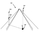
図1は、符号化されたマーカーを用いるナビゲーションシステム及び方法が実装された、ナビゲーション環境100の一実施例を表す。示される例において、符号化されたマーカー102は、道路沿いのインフラ104に配置される。例えば、そのような道路沿いのインフラは、街頭、電柱、道路標識、ビル等を含み得る。ナビゲータ106の可視範囲の中にあり、車道に最も近い、あらゆるインフラが用いられ得る。符号化されたマーカー102は、「バーコード」のような、一連の垂直の線又は水平の線として実装され得る。バーコードは、光学的に機械可読のデータ表現である。一次元バーコード及び二次元バーコードを含む、多くの種類のバーコードが、符号化されたマーカー102のために用いられ得る。一つの例において、符号化されたマーカー102は、従来のUPC(Universal Price Code)と同様の、一次元バーコードである。この例では、バーコードは、データのバイナリビット(1と0)を表す、一連の交互のバーとスペースを含む。一連のバイナリビットは、当業者によって知られるように、数値、文字、記号等を表すことができる。バーコードは、一連のグループを区切るガードバー(guard bar)と、バーコードの開始と終了を示す開始バー(starting bar)と終了バー(ending bar)をも含み得る。以下の説明と例は、主としてバーコードの利用について言及することがあるが、例えば、ブロックパターン、色分け又は英数字コードのような、他の種類の符号化されたマーカーを用い得ることが理解されるべきである。
FIG. 1 represents one embodiment of a
図2は、ナビゲーションシステム200の一実施例についてのブロック図である。ナビゲーションシステム200は、カメラ装置204のような撮像装置とともに、ビデオ分析手段(video analytics)206、プロセッサ208、符号化されたマーカーのデータベース212及びディスプレイ214を含む。ナビゲーションシステムは、以下でさらに説明するように、GPS装置210と地図データベース216を任意で含み得る。ナビゲーションシステム200は、旅行者又はハイカーの個人のナビゲーション及び/又は車両のナビゲーションのような、あらゆるナビゲーションのアプリケーションで用いられ得る。それに応じて、以下の実施例は、ナビゲーション環境を通じた車両の移動に関連して用いられるナビゲーションシステムに主として言及し、符号化されたマーカーは道路沿いのインフラに設置され得るが、ナビゲーションシステムは車両での使用に制限されず、また、符号化されたマーカーは道路沿いのインフラに制限されず、関連するナビゲーション環境の中のあらゆる場所に設置され得ることが理解されるべきである。ナビゲーションシステムは、例えば、携帯用装置、又は車両上若しくは車両内に取り付けられるよう構成された装置、又は車両内に統合され得る装置のような、内蔵型装置として実装され得る。さらに、ナビゲーションシステムは、スタンドアロンシステムであり得る。そして、専らナビゲータの位置を決定するために用いられ得るか、あるいは、以下でさらに説明されるように、GPS障害環境においてGPS衛星データを補完するために、GPS装置と連動して用いられ得る。
FIG. 2 is a block diagram for one embodiment of the
一つの実施形態によれば、カメラ装置204は、ナビゲーション環境の、視界の中の画像を取得するよう構成される。それに応じて、カメラ装置204の様々な機能を管理する制御装置とともに、一つ以上の撮像センサを含み得る。カメラ装置204は、画像、及びカメラに関する様々な機能を管理し制御するために用いられる、実行可能なプログラムを保管するためのメモリをさらに含み得る。例えば、デジタル一眼レフ(DSLR)カメラ又はデジタルコンパクトカメラ(point-and-shoot camera)のような、静止画像デジタル写真カメラを含む、異なる様々なカメラが用いられ得る。該カメラは、パノラマ式又は360度の場面の画像を撮影するために配置され得る。一つの実施形態において、前記カメラは、カメラに統合され得るか、又は取り付けられ得る、パノラマレンズを用いる。そのようなカメラレンズの一例は、デジタルカメラに取り付けられ、www.0-360.comにより提供される、0-360 PANORAMIC OPTIC(登録商標)である。0-360 PANORAMIC OPTIC(登録商標)及び関連するソフトウェアは、完全な360度の水平な視界と、115度の垂直な視界の周りの、単一の継ぎ目のないパノラマ画像を生成する。0-360 PANORAMIC OPTIC(登録商標)と組み合わされるカメラは、水平より上の52.5度から、水平より下の62.5度の画像を取得することができる。
According to one embodiment, the
一つの実施例において、カメラ装置204は、場面の連続的な写真を撮影し、その画像をビデオ分析手段206に渡す。該画像は、例えば、一秒ごと、数秒ごと、又はほんの一瞬ごとに、周期的な間隔で撮影され得る。カメラが画像を取得する速度は、変動し、あるいは調節され得る。符号化されたマーカーの十分な数の画像が取得されることを保証するために、例えば、ナビゲータが移動する速度に依存して、取得の割合を増加させることが望まれ得る。別の実施例において、カメラ装置204はビデオカメラである。ビデオカメラは、ナビゲーション環境の連続したビデオ記録を取得することができ、該ビデオ記録を、エンコーダを用いて、より小さなサイズへ圧縮することができる。圧縮されたビデオ記録のサイズは、符号化されたマーカーの画像を抽出するために必要な、記録の品質に依存し得る。一つの実施例において、カメラは、符号化されたマーカーに対する環境を監視する。符号化されたマーカーが場面の中で検出されると、ビデオカメラは、ビデオ記録に加えて、静止画像を取得し得る。
In one embodiment, the
さらに図2を参照すると、カメラによって取得された画像は、ビデオ分析手段206へ提供される。ビデオ分析手段206は、ナビゲーションの場面100の画像から、符号化されたマーカー102の画像を検出し、抽出し、処理するために、画像処理を用いる。ビデオ分析手段206は、ソフトウェア部品とハードウェア部品との両方を含んでもよく、FPGA(field-programmable gate arrays)、ASIC(application-specific integrated circuits)、マイクロコントローラ、PLD(programmable logic devices)又は他のそのような既知の装置のようなハードウェア装置を用いて実装され得る。一つの実施形態において、ビデオ分析手段206は、カメラ装置204に組み込まれる。カメラ装置204は、あらゆる照明及び/又は天候条件の下で、符号化されたマーカーの検出を改善するために、他のセンサ/装備をさらに用いることができる。例えば、高ダイナミックレンジ(HDR)カメラが、微光又は日陰の条件を補うために用いられ得る。バーコードは、微光の条件における検出を改善するために、反射性又は発光性であってもよい。
Still referring to FIG. 2, the image acquired by the camera is provided to the video analysis means 206. The video analysis means 206 uses image processing to detect, extract and process the encoded
本開示書の利益を得て、当業者により理解されるように、ピクセルイメージデコーディング又は他のカメラのオブジェクト検出技術を用いる、あらゆるビデオ分析方法又はシステムが用いられ得る。一つの実施例において、ビデオ分析手段206は、符号化されたマーカーの画像と関連する性質に一致するピクセルを特定するために、画像の中の全てのピクセルを分析する。ビデオ分析手段206は、次のピクセルへ進む前に、設定パラメータに従って一致したピクセルを処理し得る。別の実施例において、ビデオ分析手段206は、例えば、符号化されたマーカーの画像の中に含まれる特性のような、ある特性に一致するピクセルの束を識別して抽出することによる、よりインテリジェントなピクセル処理を用いる。これらのピクセルは、場面の画像からフィルタされ、個別に処理され得る。そのようなフィルタリング技術は、例えば、連続する場面の画像を比較することにより、画像の前景と背景との間とを区別することができる。フィルタは、符号化されたマーカーの画像の中に含まれる色の値の範囲と一致する特定の範囲で、特定の色の値を区別することもできる。符号化されたマーカーの画像は、周囲の環境の画像から視覚的に区別できるため、符号化されたマーカーを識別して一致させるために必要となるビデオ処理は迅速に実行されることができ、完全な「場面マッチング」のために必要なビデオ処理よりも、一般的に、はるかに単純であり得る。 Any video analysis method or system using pixel image decoding or other camera object detection techniques may be used, as will be appreciated by those skilled in the art with the benefit of this disclosure. In one embodiment, the video analysis means 206 analyzes all the pixels in the image to identify pixels that match the properties associated with the encoded marker image. Video analysis means 206 may process the matched pixels according to the set parameters before proceeding to the next pixel. In another embodiment, the video analysis means 206 is more intelligent by identifying and extracting a bundle of pixels that match certain characteristics, such as, for example, characteristics included in the encoded marker image. Use pixel processing. These pixels can be filtered from the scene image and processed individually. Such filtering techniques can distinguish between the foreground and background of an image, for example, by comparing images of successive scenes. The filter can also distinguish specific color values by a specific range that matches the range of color values contained in the encoded marker image. Because the encoded marker image can be visually distinguished from the surrounding environment image, the video processing required to identify and match the encoded marker can be performed quickly, It may generally be much simpler than the video processing required for complete “scene matching”.
図3は、一実施形態に従う、ナビゲータの位置を決定する方法300を示す。カメラ装置204は、一つ以上の符号化されたマーカー102を含む、ナビゲーションの場面100の画像を取得することができる(ステップ302)。ステップ304において、ビデオ分析手段206は、場面の画像から、符号化されたマーカーの画像を抽出するために、場面の画像を処理し、前記マーカーを復号化することにより、符号化されたマーカーを読み取る。ステップ306は、符号化されたマーカーの位置を決定する段階を含む。上述したように、符号化されたマーカー102は、UPCバーコードのような、一連の水平のバー又は垂直のバーであってもよい。バーとスペースの群は、いくつかの数字を表し得る。一連の数字は、符号化されたマーカーの識別値又はデータベースの値であり得る。それらの値は、プロセッサ208によって、符号化されたマーカーのデータベース212の中の、符号化されたマーカーの既知の配置位置に対して比較され得る。代わりに、一連の数字は、経度と緯度のような、符号化されたマーカー102の位置情報を表す地理座標へと変換されてもよい。一度、符号化されたマーカーの位置がわかると、ナビゲータの位置が決定される(ステップ308)。一つの実施例において、以下でさらに説明されるように、このことは、ナビゲータの、符号化されたマーカーへの相対的な方位角及び/又は距離を決定することにより達成される。方法300は、ナビゲータの場所に関する複数の位置を決定するために、連続的か、あるいは所定の間隔で繰り返され得る。
FIG. 3 illustrates a
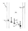
図4は、符号化されたマーカーからナビゲータの位置を決定する例を表す。図4は、場面の画像400、道路インフラ104、及びX1とX2とラベル付けされた、符号化されたマーカー102を含む。上述したように、符号化されたマーカー102は、ナビゲーション環境100の中の道路インフラ104上に設置されたバーコードであり得る。場面400の画像は、上述したように、カメラ装置204により取得される。一つの実施形態において、プロセッサ208は、画像400を処理することにより、ナビゲータの位置を決定する。プロセッサ208は、FPGA、ASIC、マイクロコントローラ、PLD又は当該技術分野で既知の、他のそのような装置のような、ハードウェア装置を用いて実装され得る。上述したように、プロセッサ208は、ビデオ分析手段206の一部又は別個の要素であり得る。一つの実施形態において、プロセッサ208は、符号化されたマーカーの画像の相対的な方位角のオフセット(azimuth offset)を決定し、該オフセットに基づいてナビゲータの位置を幾何学的に決定することにより、ナビゲータの位置を決定する。道路のインフラ104と符号化されたマーカーへの方位角のオフセットは、相対的な方位角の値がゼロであるところ(当然に、一般的にナビゲータの前方向と一致する)からの偏差402である、正の値又は負の値を決定することにより見出される。いくつかの実施例において、符号化されたマーカー102とナビゲータとの間の距離がさらに決定され、以下で説明されるように、ナビゲータの絶対位置を決定するために、偏差402とともに用いられる。
FIG. 4 shows an example of determining the position of the navigator from the encoded marker. FIG. 4 includes a
図5Aは、(X1のラベルが付された)ある符号化されたマーカー102に基づいてナビゲータ106の位置を決定する、一つの実施例である。この実施例では、ナビゲータは、道路502上に位置すると仮定し、矢印504によって表されるナビゲータの向きは、道路の向きと一致すると仮定する。この実施例では、一つの符号化されたマーカーX1の検出及び読み取りにより、ナビゲータと符号化されたマーカーX1との間の視線(line-of-sight)506上のどこかに、ナビゲータ106があることが認識される。しかしながら、ナビゲータと符号化されたマーカーとの間の距離のような、追加的な情報がないため、ナビゲータの正確な位置を決定することができない。この実施例は、ナビゲータ106の位置のおおまかな見積もりを提供し、いくつかのアプリケーションにとってはそれが十分であり得る。しかしながら、図5Bに示されるように、上で示した仮定を前提として、ナビゲータと符号化されたマーカーとの間の距離に関するあらゆる情報を必要とすることなく、二つの符号化されたマーカー102の検出と読み取りによってナビゲータ106の正確な位置を決定することができる。具体的に言うと、同時に二つの異なる符号化されたマーカー102への相対的な方位角を取得することにより(すなわち、二つの符号化されたマーカーを含む同一の画像を処理することにより)、決定された方位角のオフセットにおいて、カメラ204の位置、すなわちナビゲータ106の位置で交差する、二つの直線を二つの符号化されたマーカーから引くことができる。そうして、画像400が取得された時点のナビゲータの位置を提供する。この三角測量の方法は、二つの符号化されたマーカー102が、ナビゲータからマーカーまでの距離に関わらず画像400の中で読み取ることができるという条件で、用いることができる。図5Cにおいて示されるように、ナビゲータ106の場所及び/又は向きに関して何ら仮定がなされず、あらゆるマーカーまでの距離の情報がない場合には、二つのマーカーの検出と読み取りは、ナビゲータの位置の大まかな見積もりを提供するが、ある特定の位置のナビゲータを認識することができない。従って、ナビゲータ106と、検出された、符号化されたマーカー102との間の相対的な方位角のオフセットの決定は、ナビゲータの大まかな位置、あるいはいくつかの環境においては正確な位置を取得するために用いることができる。
FIG. 5A is an example of determining the position of
図4を再度参照すると、別の実施形態において、プロセッサ208は、符号化されたマーカーの画像の寸法(dimension)を決定し、符号化されたマーカーからのナビゲータの距離を決定することにより、ナビゲータの絶対位置を決定する。図4で示されるように、バーコードは、高さ404と幅406の寸法を有する。符号化されたマーカーの画像の高さは、カメラから一定の距離離れた地点における画像の中のピクセル数によって数値化され得る。例えば、5ピクセルは、カメラから一定の距離離れた地点における1ミリメートルの高さを表し得る。符号化されたマーカーの高さ404を用いて、符号化されたマーカーからのナビゲータの距離が推定され得る。その関係は、正比例し得る。言い換えれば、画像400の中に現れる符号化されたマーカーの高さが高いほど、符号化されたマーカーはナビゲータに近い。プロセッサ208は、カメラから一定距離離れた地点における、符号化されたマーカーの所定の高さに基づいて、ナビゲータの位置を決定することができる。
Referring back to FIG. 4, in another embodiment, the
ナビゲーションシステムは、上述した、ナビゲータの位置を決定する方法のいずれか、あるいは両方を用いることができる。一つの実施形態において、二つの符号化されたマーカーがカメラで確認できる場合には、ナビゲータの絶対位置を決定するために、相対的な方位角を用いる幾何学的な決定方法のみが用いられる。ナビゲーション環境において、一つの符号化されたマーカーのみが可視である場合には、ナビゲータの絶対位置は、幾何学的な決定方法によって取得されないことがある。従って、絶対位置が望まれる場合には、マーカーの寸法による方法が代わりに用いられ得る。別の実施形態において、プロセッサ208は、ナビゲータの絶対位置を決定するために、幾何学的な決定方法と、マーカーの寸法の方法とを組み合わせるよう構成される。
The navigation system can use either or both of the methods described above for determining the position of the navigator. In one embodiment, if two encoded markers are visible on the camera, only a geometric determination method using relative azimuth is used to determine the absolute position of the navigator. In the navigation environment, if only one encoded marker is visible, the absolute position of the navigator may not be obtained by a geometric determination method. Thus, if absolute position is desired, the marker size method can be used instead. In another embodiment, the
図6は、例えば、相対的な方位角の決定を用いて、場面400の連続する画像から、マーカーまでの距離の情報と、ナビゲータの絶対位置との両方を幾何学的に決定する一つの例を表す。計算のために、道路の方向は、ナビゲータの向き及び相対的な方位角がゼロの向きと一致すると仮定する。画像は、ナビゲータP1及びP2の位置で取得され、その画像の間に移動した距離であるΔdは、以下の式で計算される。
Δd = V Δt;
ここで、Vはナビゲータの速度であり、Δtは、P1とP2とが画像が取得される間の時間である。符号化されたマーカーX1とそれぞれの位置P1及びP2におけるナビゲータ106との間の相対的な変位角Az1及びAz2が、二つの画像から決定される。三角形602は、符号化されたマーカーX1からナビゲータの位置P1及びP2へ直線を引き、さらに位置P1とP2との間に直線を引くことにより、形成される。それぞれの位置における、符号化されたマーカーX1からのナビゲータの距離d1及びd2は、それぞれ、余弦の法則に従って、以下の式から決定され得る。
d12 = d22 + Δd2 - 2 Δd d2 cos(180 - Az2);
d22 = d12 + Δd2 - 2 Δd d1 cos(Az1)
二つの符号化されたマーカーX1及びX2が、両方ともに画像400の中で可視である場合には、ナビゲータのそれぞれの位置P1及びP2と、第二の符号化されたマーカーX2との間の相対的な方位角と距離は、同様に決定され得る。本開示書の利益を得て、当業者によって理解されるように、一つの符号化されたマーカー102のみが可視であり、ナビゲータの向きが道路の向きと一致しない場合には、ナビゲータ106の正確な位置を決定することはできない。一方で、複数の符号化されたマーカーが、十分に離れたΔdとなるナビゲータの位置P1とP2とにおいて、取得された連続する画像で可視であれば、それらの位置の間のナビゲータの正確な位置及び正確な向きは、明確に計算することができる。
FIG. 6 illustrates one example of geometrically determining both distance information to the marker and the absolute position of the navigator from successive images of the
Δd = V Δt;
Here, V is the navigator speed, and Δt is the time during which P1 and P2 are acquired. The relative displacement angles Az1 and Az2 between the encoded marker X1 and the
d1 2 = d2 2 + Δd 2 - 2 Δd d2 cos (180 - Az2);
d2 2 = d1 2 + Δd 2 - 2 Δd d1 cos (Az1)
If the two encoded markers X1 and X2 are both visible in the
上述した方法及びシステムは、ナビゲータの連続的な位置情報を提供し、符号化されたマーカーから取得される位置データを補完するために、位置決定の間(in-between)に推測位置(dead reckoning)計算を実行することができる。そのような推測位置計算は、従来のGPSを利用したシステムにおいて、GPS装置によって受信された衛星データの実現値(instance)の合間に度々実行される。それに応じて、図7は、位置決定の間の推測位置の使用を含む、ナビゲータの位置の決定方法の別の例のフロー図を表す。上述したように、方法700は、符号化されたマーカーを含む、場面の画像を取得する段階(ステップ302)と、該画像の中の符号化されたマーカーを読み取る段階と、該符号化されたマーカーの位置を決定する段階(ステップ304とステップ306)とを含む。該ステップは、前記符号化されたマーカーの配置位置を決定するために、データベースの中の前記符号化されたマーカーの識別値を探索する段階(ステップ702)を含み得る。あるいは、該ステップは、前記符号化されたマーカーの位置を取得するために、例えば、上述したように、緯度と経度へ直接に復号化する段階(ステップ704)を含み得る。方法700は、前記ナビゲータの位置を取得する段階(ステップ308)をさらに含む。該段階は、前記ナビゲータからの前記符号化されたマーカーの距離を決定する段階(ステップ706)、及び/又は、上述したように、前記ナビゲータの向きと前記符号化されたマーカーとの間の相対的な方位角を決定する段階(ステップ708)を含み得る。一つの実施形態において、方法700は、前記ナビゲータの連続的な位置を提供するために、推測位置計算を実行する段階(ステップ710)をさらに含み、任意で、地図を利用したディスプレイ上に前記ナビゲータの位置を表示する段階(ステップ712)を含む。ステップ308において前記ナビゲータの位置が取得された後に、推測位置計算が実行され(ステップ710)、その結果、前記ナビゲータの連続した位置が提供される。
The method and system described above provide continuous position information of the navigator and dead reckoning during in-between to complement the position data obtained from the encoded markers. ) Calculations can be performed. Such an estimated position calculation is frequently executed in the interval between the actual values of the satellite data received by the GPS device in a conventional system using GPS. Accordingly, FIG. 7 depicts a flow diagram of another example of a navigator position determination method that includes the use of inferred positions during position determination. As described above,
一つの実施例において、推測位置計算は、ナビゲータの開始位置に注目し、ナビゲータの速度及び/又は加速/減速、並びにナビゲータの経路又は向きを監視することにより、ナビゲータの位置を推定する。推測位置計算は、ナビゲータが同一の向きに同一の速度/加速で移動した場合に、ナビゲータの位置を推定する。推測位置計算を用いて取得される位置の正確さは、センサデータの正確さと利用可能性に依存することが理解され得る。このデータを得るために、異なる技術が用いられてもよい。例えば、システムは、車両と関連し得る、差分若しくは数字の速度情報、オドメータのパルス、加速度計、レーダ、光学若しくは音響センサ、タコメータ及び/又はジャイロスコープのような、様々なセンサを用いることができる。システムの他の実施形態は、道路のカーブ及び曲がり角に沿ってナビゲータのコースをより正確にプロットするために、センサからのデータを地図データと組み合わせ得る。 In one embodiment, the estimated position calculation estimates the navigator position by noting the navigator start position and monitoring the navigator speed and / or acceleration / deceleration and the navigator path or orientation. The estimated position calculation estimates the position of the navigator when the navigator moves in the same direction at the same speed / acceleration. It can be seen that the accuracy of the position obtained using the inferred position calculation depends on the accuracy and availability of the sensor data. Different techniques may be used to obtain this data. For example, the system may use various sensors, such as differential or numerical velocity information, odometer pulses, accelerometers, radar, optical or acoustic sensors, tachometers and / or gyroscopes that may be associated with the vehicle. . Other embodiments of the system may combine data from sensors with map data in order to more accurately plot the navigator's course along the road curves and turns.
一般的なGPSナビゲーションシステムは、道路網を表す地図データベース、及び道路網の視覚表示を表す、地図を利用したディスプレイと統合される。これらのナビゲーションシステムは、GPSを利用した位置を地図データベースと関連付け、地図を利用したディスプレイ上にナビゲータの位置を表示する。一つの実施形態によれば、当該ナビゲーションシステムは、そのような地図データベース216と地図を利用したディスプレイ214とを含む。あるいは、当該ナビゲーションシステムは、地図データベースと地図を利用したディスプレイを含むGPSを利用したシステムへと統合される。一つの実施例において、位置情報を取得するGPSは、符号化されたマーカーから取得される位置と置き換えられるか、あるいは補完される。一つの実施形態において、ステップ710において取得される連続的な位置情報は、地図データベース216と関連付けられ、ディスプレイ214上に表示される(ステップ712)。地図データベース216は、道路のネットワークを表し、基本要素及びその特性を含む。基本要素は、ノード、リンク及び領域から構成され得る。基本要素の特性は、それらの要素の地理座標、領域の形状、ノードのアドレス及び/又はリンクの道路区分を表す。道路網は、さらにPOI(points of interest)を含んでもよい。符号化されたマーカーの既知の位置は、地図データベース216の中の参照のノード又は点として符号化され得る。
A typical GPS navigation system is integrated with a map database representing a road network and a map-based display representing a visual display of the road network. These navigation systems associate a position using GPS with a map database and display the position of the navigator on a display using a map. According to one embodiment, the navigation system includes such a
一つの実施例において、ナビゲーションシステム200のディスプレイ214は、道路網の視覚表示(visual representation)を表示する。視覚表示は、インタラクティブな三次元(3D)の地図の形式であり得る。視覚表示は、基本要素及びナビゲータの付近における道路網のPOIを表し得る。ナビゲータ102がナビゲーション環境100を通じて移動するにつれ、3D地図はナビゲータとともに移動し、変化する要素に適応し得る。3D地図は、既知の、符号化されたマーカー102の位置及びナビゲータの位置をさらに表示する。液晶ディスプレイ(LCD)、プラズマディスプレイ又は発光ダイオード(LED)ディスプレイを含む、あらゆる種類のディスプレイが利用され得る。
In one embodiment, the
上述したように、一つの実施形態において、ナビゲーションシステム200は、GPS装置210と統合される。GPS信号が利用可能である場合には、GPS装置210は送信GPS衛星から情報を受信し、ナビゲータの位置を決定するためにそのデータを利用する。例えば、GPS装置210は、ナビゲータの位置を決定するために、一つのGPS衛星からのデータを、他のGPS衛星から受信したデータとを比較することにより、三角測量の計算を実行することができる。しかしながら、上述したように、「GPS障害」環境において、GPS装置210は、GPS衛星への視線がブロックされることにより、GPS衛星からの情報を受信することができないことがある。例えば、ナビゲータが、都市の谷間、駐車場ビル、木の近く、若しくはトンネル内にある場合、あるいは信号の反射又はマルチパス伝搬による場合である。ナビゲータが「GPS障害」環境を出た後であっても、GPS装置は、ナビゲータの位置をすぐに決定できないことがある。これらの状況、あるいは同様の状況及びこれらのGPS障害環境において、ナビゲータの位置は、上述したように、符号化されたマーカーを用いて決定することができる。
As described above, in one embodiment, the
例えば、図8のステップ802において、方法800は、GPS受信がGPS装置210を用いて可能かどうかを決定する段階を含む。GPS受信が利用可能である場合には、GPS装置は、一般的なGPS位置による方法を用いてナビゲータの位置を取得する(ステップ804)。GPS受信が利用手可能である場合には、当該方法は、上述したように、符号化されたマーカーによる方法300又は方法700を用いてナビゲータの位置を取得する。この位置は、GPS障害環境においてGPS装置により決定された位置情報を補完するか、あるいは置換し得る。別の位置が後続の符号化されたマーカーから取得されるまで、あるいは代わりに、受信がGPS装置に保管されるまで、上述したような、推測位置計算が実行される。この結果は、ナビゲータの連続的な位置情報であり、任意で地図データベース216へ関連付けられ、ディスプレイ214上に表示され得る。
For example, in
少なくとも一つの実施形態の複数の実施例について説明したが、当業者が様々な代替、修正及び改良に容易に気がつき得ることを理解すべきである。そのような代替、修正及び改良は、この開示書の部分であることが意図され、さらに本発明の範囲内であることが意図される。従って、先述の説明及び図面は例示する目的のみによって存在し、本発明の範囲は、添付されるクレームの適切な構成及びそれらの均等物から決定されるべきである。 Although several examples of at least one embodiment have been described, it should be understood that various alternatives, modifications and improvements will be readily apparent to those skilled in the art. Such alternatives, modifications and improvements are intended to be part of this disclosure and are further intended to be within the scope of the present invention. Accordingly, the foregoing description and drawings are for illustrative purposes only, and the scope of the present invention should be determined from the proper construction of the appended claims and their equivalents.
206 ビデオ分析手段
208 プロセッサ
210 GPS装置
212 符号化されたマーカーのデータベース
214 ディスプレイ
216 地図データベース
206 Video analysis means 208
Claims (21)
少なくとも一つの符号化されたマーカーを含む場面の画像を取得する段階と;
前記画像の中の前記少なくとも一つの符号化されたマーカーを読み取る段階と;
前記少なくとも一つの符号化されたマーカーの既知の場所に基づいて、前記ナビゲータの場所に関する位置を決定する段階と;
を有する、方法。 A method for determining the position of a navigator:
Obtaining an image of a scene including at least one encoded marker;
Reading the at least one encoded marker in the image;
Determining a position relative to the location of the navigator based on a known location of the at least one encoded marker;
Having a method.
前記場面の前記画像から、前記少なくとも一つの符号化されたマーカーの一つの画像を抽出する段階と;
前記少なくとも一つの符号化されたマーカーの一つの前記画像をデータベースの値へ復号化する段階と;
前記データベースの値に基づいて前記少なくとも一つの符号化されたマーカーの一つの前記既知の場所を読み出すためにデータベースにアクセスする段階と;
をさらに有する、請求項1に記載の方法。 The reading step includes:
Extracting an image of the at least one encoded marker from the image of the scene;
Decoding one of the images of the at least one encoded marker into a database value;
Accessing the database to retrieve one of the known locations of the at least one encoded marker based on the value of the database;
The method of claim 1, further comprising:
前記場面の前記画像から、前記少なくとも一つの符号化されたマーカーの一つの画像を抽出する段階と;
前記少なくとも一つの符号化されたマーカーの一つの前記画像を前記少なくとも一つの符号化されたマーカーの一つの前記既知の場所へと復号化する段階と;
をさらに有する、請求項1に記載の方法。 The reading step includes:
Extracting an image of the at least one encoded marker from the image of the scene;
Decoding the image of one of the at least one encoded marker into the known location of one of the at least one encoded marker;
The method of claim 1, further comprising:
前記ナビゲータと前記場面の前記画像の中の前記少なくとも一つの符号化されたマーカーとの間の相対的な方位角のオフセットを決定する段階と;
前記相対的な方位角のオフセットから前記ナビゲータの前記位置を幾何学的に計算する段階と;
をさらに有する、請求項1に記載の方法。 The step of determining is:
Determining a relative azimuthal offset between the navigator and the at least one encoded marker in the image of the scene;
Geometrically calculating the position of the navigator from the relative azimuthal offset;
The method of claim 1, further comprising:
前記場面の前記画像の中の前記少なくとも一つの符号化されたマーカーの寸法を決定することにより前記ナビゲータから前記符号化されたマーカーまでの距離を決定する段階;
をさらに有する、請求項1に記載の方法。 The step of determining is:
Determining a distance from the navigator to the encoded marker by determining a dimension of the at least one encoded marker in the image of the scene;
The method of claim 1, further comprising:
前記決定する段階は:
前記場面の前記複数の画像から、前記ナビゲータと前記少なくとも一つの符号化されたマーカーとの間の、対応する複数の相対的な方位角のオフセットを決定する段階と;
前記マーカーへの前記複数の相対的な方位オフセットに基づいて前記ナビゲータから前記少なくとも一つの符号化されたマーカーまでの距離を決定する段階と;
をさらに有する、請求項1に記載の方法。 The step of acquiring includes acquiring a plurality of images of the scene at different times during which the navigator is moving;
The step of determining is:
Determining from the plurality of images of the scene a corresponding plurality of relative azimuthal offsets between the navigator and the at least one encoded marker;
Determining a distance from the navigator to the at least one encoded marker based on the plurality of relative orientation offsets to the marker;
The method of claim 1, further comprising:
をさらに有する、請求項1に記載の方法。 The method of claim 1, further comprising: associating the location for the navigator location with map data.
360度カメラを用いて前記画像を取得する段階
をさらに有する。請求項1に記載の方法。 The obtaining step includes
The method further includes acquiring the image using a 360 degree camera. The method of claim 1.
GPS装置を用いて前記ナビゲータの位置情報を取得する段階と;
GPS障害環境において、前記GPS装置からの前記位置情報を前記少なくとも一つの符号化されたマーカーから取得される前記位置を用いて補完する段階と;
をさらに有する、請求項1に記載の方法。 The step of determining is:
Obtaining position information of the navigator using a GPS device;
Supplementing the location information from the GPS device with the location obtained from the at least one encoded marker in a GPS fault environment;
The method of claim 1, further comprising:
複数の位置を決定する段階と;
前記ナビゲータの連続的な位置を提供するために、前記複数の位置の間の推測位置計算を実行する段階と;
をさらに有する、請求項1に記載の方法。 The step of determining is:
Determining a plurality of positions;
Performing an estimated position calculation between the plurality of positions to provide a continuous position of the navigator;
The method of claim 1, further comprising:
前記ナビゲータの速度を監視する段階と;
前記ナビゲータの方向を決定する段階と;
前記複数の位置の一つと車両の前記速度と前記方向とに基づいて前記ナビゲータの前記位置を推定する段階と;
を有する、請求項10に記載の方法。 The steps of performing an estimated position calculation between the plurality of positions are:
Monitoring the speed of the navigator;
Determining the direction of the navigator;
Estimating the position of the navigator based on one of the plurality of positions and the speed and direction of the vehicle;
The method of claim 10, comprising:
少なくとも一つのバーコードを含む前記場面の前記画像を取得する段階をさらに含む、
請求項1に記載の方法。 The obtaining step includes
Further comprising obtaining the image of the scene including at least one barcode;
The method of claim 1.
ナビゲーション環境の中の少なくとも一つの符号化されたマーカーの画像を含む場面の画像を取得するよう構成されるカメラ装置と;
前記少なくとも一つの符号化されたマーカーを読み取るよう構成されるビデオ分析手段と;
前記ビデオ分析手段と接続され、前記少なくとも一つの符号化されたマーカーの既知の場所に基づいてナビゲータの位置を決定するよう構成されるプロセッサと;
を有する、ナビゲーションシステム。 Navigation system:
A camera device configured to acquire an image of a scene including an image of at least one encoded marker in a navigation environment;
Video analysis means configured to read the at least one encoded marker;
A processor connected to the video analysis means and configured to determine a position of the navigator based on a known location of the at least one encoded marker;
A navigation system.
前記少なくとも一つの符号化されたマーカーの少なくとも一つの前記既知の場所に関連する少なくとも一つのデータベースの値と;
を有するデータベースをさらに含み、
前記ビデオ分析手段は、前記場面の前記画像から前記少なくとも一つの符号化されたマーカーの前記画像を抽出し、前記少なくとも一つの符号化されたマーカーの前記画像を前記少なくとも一つのデータベースの値へと変換するようさらに構成される、
請求項13に記載のナビゲーションシステム。 At least one known location of the at least one encoded marker;
At least one database value associated with the at least one known location of the at least one encoded marker;
Further including a database having
The video analysis means extracts the image of the at least one encoded marker from the image of the scene and converts the image of the at least one encoded marker into a value of the at least one database. Further configured to convert,
The navigation system according to claim 13.
請求項13に記載のナビゲーションシステム。 The processor determines a relative azimuth offset between the navigator and the at least one encoded marker in the image of the scene, and from the relative azimuth offset, the navigator. Further configured to determine the position relative to the location of the navigator by geometrically calculating the position of
The navigation system according to claim 13.
前記ナビゲータの、前記少なくとも一つの符号化されたマーカーの一つまでの距離を決定することにより、前記ナビゲータの場所に関する前記位置を決定するようさらに構成される、
請求項13に記載のナビゲーションシステム。 The processor is
Further configured to determine the position relative to the location of the navigator by determining a distance of the navigator to one of the at least one encoded marker.
The navigation system according to claim 13.
前記地図データベースの視覚表示を表示し、該視覚表示の中に前記ナビゲータの前記位置を配置するよう構成されるディスプレイと、
をさらに有する、請求項13に記載のナビゲーションシステム。 A map database, wherein the processor is configured to associate the location of the navigator with the map database;
A display configured to display a visual display of the map database and to place the position of the navigator in the visual display;
The navigation system according to claim 13, further comprising:
前記プロセッサは、前記GPS装置から取得される前記ナビゲータの前記位置情報を前記少なくとも一つの符号化されたマーカーの前記既知の場所に基づく位置を用いて補完するよう構成される、
請求項13に記載のナビゲーションシステム。 Further comprising a GPS device configured to obtain position information of the navigator;
The processor is configured to supplement the position information of the navigator obtained from the GPS device with a position based on the known location of the at least one encoded marker;
The navigation system according to claim 13.
前記少なくとも一つの符号化されたマーカーの前記既知の場所に基づいて複数の位置を取得し、
前記ナビゲータの連続的な位置を提供するために、前記複数の位置の間の推測位置計算を実行する
ようさらに構成される、請求項13に記載のナビゲーションシステム。 The processor is
Obtaining a plurality of positions based on the known location of the at least one encoded marker;
The navigation system of claim 13, further configured to perform an estimated position calculation between the plurality of positions to provide a continuous position of the navigator.
請求項13に記載のナビゲーションシステム。 The at least one encoded marker comprises at least one barcode;
The navigation system according to claim 13.
請求項13に記載のナビゲーションシステム。 The camera device has a 360 degree camera,
The navigation system according to claim 13.
Applications Claiming Priority (2)
| Application Number | Priority Date | Filing Date | Title |
|---|---|---|---|
| US13/017,376 US8862395B2 (en) | 2011-01-31 | 2011-01-31 | Coded marker navigation system and method |
| US13/017,376 | 2011-01-31 |
Publications (3)
| Publication Number | Publication Date |
|---|---|
| JP2012159506A true JP2012159506A (en) | 2012-08-23 |
| JP2012159506A5 JP2012159506A5 (en) | 2014-10-30 |
| JP5841849B2 JP5841849B2 (en) | 2016-01-13 |
Family
ID=45569751
Family Applications (1)
| Application Number | Title | Priority Date | Filing Date |
|---|---|---|---|
| JP2012016777A Active JP5841849B2 (en) | 2011-01-31 | 2012-01-30 | Navigation system and method using encoded markers |
Country Status (3)
| Country | Link |
|---|---|
| US (1) | US8862395B2 (en) |
| JP (1) | JP5841849B2 (en) |
| WO (1) | WO2012106156A1 (en) |
Cited By (7)
| Publication number | Priority date | Publication date | Assignee | Title |
|---|---|---|---|---|
| JP2016136099A (en) * | 2015-01-23 | 2016-07-28 | サトーホールディングス株式会社 | Positioning system and positioning method |
| KR20170022766A (en) * | 2015-08-21 | 2017-03-02 | 현대모비스 주식회사 | Positioning apparatus for vehicle and method thereof |
| CN108885113A (en) * | 2016-04-08 | 2018-11-23 | 罗伯特·博世有限公司 | Method for determining the posture of the vehicle at least partly automating traveling in ambient enviroment by terrestrial reference |
| JP2019504300A (en) * | 2016-06-22 | 2019-02-14 | 平安科技(深▲せん▼)有限公司 | Indoor navigation method using portable terminal, portable terminal, and storage medium |
| WO2019098353A1 (en) * | 2017-11-17 | 2019-05-23 | アイシン精機株式会社 | Vehicle position estimation device and vehicle control device |
| JP2019120629A (en) * | 2018-01-10 | 2019-07-22 | 三菱電機株式会社 | Position calculation device, position calculation program, and coordinate marker |
| JP2020009391A (en) * | 2018-07-09 | 2020-01-16 | 株式会社ANswer | Method and system for positional information service |
Families Citing this family (49)
| Publication number | Priority date | Publication date | Assignee | Title |
|---|---|---|---|---|
| US10878646B2 (en) | 2005-12-08 | 2020-12-29 | Smartdrive Systems, Inc. | Vehicle event recorder systems |
| US8996240B2 (en) | 2006-03-16 | 2015-03-31 | Smartdrive Systems, Inc. | Vehicle event recorders with integrated web server |
| US8989959B2 (en) | 2006-11-07 | 2015-03-24 | Smartdrive Systems, Inc. | Vehicle operator performance history recording, scoring and reporting systems |
| US8649933B2 (en) | 2006-11-07 | 2014-02-11 | Smartdrive Systems Inc. | Power management systems for automotive video event recorders |
| US8868288B2 (en) | 2006-11-09 | 2014-10-21 | Smartdrive Systems, Inc. | Vehicle exception event management systems |
| US9395188B2 (en) * | 2011-12-01 | 2016-07-19 | Maxlinear, Inc. | Method and system for location determination and navigation using structural visual information |
| US9728228B2 (en) | 2012-08-10 | 2017-08-08 | Smartdrive Systems, Inc. | Vehicle event playback apparatus and methods |
| DE102012224107A1 (en) | 2012-12-20 | 2014-06-26 | Continental Teves Ag & Co. Ohg | Method for determining a reference position as starting position for an inertial navigation system |
| EP2943804B1 (en) * | 2013-01-09 | 2016-09-28 | Telefonaktiebolaget LM Ericsson (publ) | Supporting and enhancing image-based positioning |
| US10163049B2 (en) * | 2013-03-08 | 2018-12-25 | Microsoft Technology Licensing, Llc | Inconspicuous tag for generating augmented reality experiences |
| JP2015055534A (en) * | 2013-09-11 | 2015-03-23 | 株式会社リコー | Information processing apparatus, control program thereof, and control method thereof |
| US9501878B2 (en) | 2013-10-16 | 2016-11-22 | Smartdrive Systems, Inc. | Vehicle event playback apparatus and methods |
| US9610955B2 (en) | 2013-11-11 | 2017-04-04 | Smartdrive Systems, Inc. | Vehicle fuel consumption monitor and feedback systems |
| US9593953B2 (en) * | 2014-01-21 | 2017-03-14 | Telenav, Inc. | Navigation system with location correction mechanism and method of operation thereof |
| CN103776443A (en) * | 2014-01-28 | 2014-05-07 | 北京融智利达科技有限公司 | Autonomous navigation system for producing correction information by using image information code |
| US8892310B1 (en) | 2014-02-21 | 2014-11-18 | Smartdrive Systems, Inc. | System and method to detect execution of driving maneuvers |
| JP6233517B2 (en) * | 2014-07-17 | 2017-11-22 | 日本電気株式会社 | Airspace information processing apparatus, airspace information processing method, airspace information processing program |
| CN112904880A (en) * | 2014-10-31 | 2021-06-04 | 深圳市大疆创新科技有限公司 | System and method for monitoring with visual indicia |
| US11069257B2 (en) | 2014-11-13 | 2021-07-20 | Smartdrive Systems, Inc. | System and method for detecting a vehicle event and generating review criteria |
| US10001376B1 (en) * | 2015-02-19 | 2018-06-19 | Rockwell Collins, Inc. | Aircraft position monitoring system and method |
| US9679420B2 (en) | 2015-04-01 | 2017-06-13 | Smartdrive Systems, Inc. | Vehicle event recording system and method |
| US9758305B2 (en) | 2015-07-31 | 2017-09-12 | Locus Robotics Corp. | Robotic navigation utilizing semantic mapping |
| US10176718B1 (en) * | 2015-09-25 | 2019-01-08 | Apple Inc. | Device locator |
| US10354531B1 (en) | 2015-09-25 | 2019-07-16 | Apple Inc. | System and method for identifying available parking locations |
| CN105955252A (en) * | 2016-04-12 | 2016-09-21 | 江苏理工学院 | Intelligent voice tour guide robot and path optimizing method thereof |
| SG11201809405RA (en) * | 2016-04-28 | 2018-11-29 | Aichi Steel Corp | Driving assistance system |
| EP3481661A4 (en) | 2016-07-05 | 2020-03-11 | Nauto, Inc. | System and method for automatic driver identification |
| JP6312754B2 (en) * | 2016-08-04 | 2018-04-18 | 三菱電機株式会社 | Vehicle travel control device and vehicle travel control method |
| JP2019527832A (en) | 2016-08-09 | 2019-10-03 | ナウト, インコーポレイテッドNauto, Inc. | System and method for accurate localization and mapping |
| US10733460B2 (en) | 2016-09-14 | 2020-08-04 | Nauto, Inc. | Systems and methods for safe route determination |
| WO2018085689A1 (en) * | 2016-11-03 | 2018-05-11 | Laine Juha Pekka J | Camera-based heading-hold navigation |
| CN110178104A (en) | 2016-11-07 | 2019-08-27 | 新自动公司 | System and method for determining driver distraction |
| US10754348B2 (en) * | 2017-03-28 | 2020-08-25 | Uatc, Llc | Encoded road striping for autonomous vehicles |
| WO2018229550A1 (en) | 2017-06-16 | 2018-12-20 | Nauto Global Limited | System and method for adverse vehicle event determination |
| EP3659116A4 (en) | 2017-07-27 | 2021-04-28 | Westinghouse Electric Company Llc | Method of locating a remotely operated vehicle within a workspace and remote inspection system employing such method |
| DE102017118078A1 (en) * | 2017-08-09 | 2019-02-14 | Safran Electronics & Defense | Localization device for a motor vehicle, driver assistance device, motor vehicle and method for locating a motor vehicle |
| CN109813314A (en) * | 2017-11-21 | 2019-05-28 | 程梦梦 | A kind of method of indoor and outdoor precision navigation positioning |
| US11392131B2 (en) | 2018-02-27 | 2022-07-19 | Nauto, Inc. | Method for determining driving policy |
| US20190275616A1 (en) * | 2018-03-06 | 2019-09-12 | Goodrich Corporation | Method for improving visual contrast of laser etch marking on painted substrates |
| CN109859457A (en) * | 2018-12-25 | 2019-06-07 | 南京硅基智能科技有限公司 | A kind of direction giving system based on two dimensional code identification and interactive voice |
| DE102019203484A1 (en) * | 2019-03-14 | 2020-09-17 | Zf Friedrichshafen Ag | Method, device and system for the navigation of autonomous vehicles |
| US10623734B1 (en) * | 2019-04-23 | 2020-04-14 | Nuro, Inc. | Systems and methods for adaptive mobile telecommunications for autonomous vehicles |
| US11334089B1 (en) | 2019-07-26 | 2022-05-17 | Jeffrey W. Bryce | Infrastructure markers for autonomous vehicles |
| IL269263B (en) * | 2019-09-10 | 2021-09-30 | Veeride Geo Ltd | Cellular-based navigation method |
| JP6988873B2 (en) * | 2019-11-18 | 2022-01-05 | トヨタ自動車株式会社 | Position estimation device and computer program for position estimation |
| US20230069480A1 (en) | 2020-02-13 | 2023-03-02 | Tinamu Labs Ag | Uav positioning system and method for controlling the position of an uav |
| US11560143B2 (en) * | 2020-05-26 | 2023-01-24 | Magna Electronics Inc. | Vehicular autonomous parking system using short range communication protocols |
| US11808578B2 (en) * | 2020-05-29 | 2023-11-07 | Aurora Flight Sciences Corporation | Global positioning denied navigation |
| JP2022074917A (en) * | 2020-11-05 | 2022-05-18 | 本田技研工業株式会社 | Autonomous work system |
Citations (8)
| Publication number | Priority date | Publication date | Assignee | Title |
|---|---|---|---|---|
| JPH11353579A (en) * | 1998-05-29 | 1999-12-24 | Mitsubishi Electric Corp | System and method for determining position of vehicle on road |
| JP2001118187A (en) * | 1999-10-19 | 2001-04-27 | Olympus Optical Co Ltd | Information display member and position detection method using the same |
| JP2001343213A (en) * | 2000-06-01 | 2001-12-14 | Minolta Co Ltd | Position-specifying apparatus loaded to mobile body |
| US6577249B1 (en) * | 1999-10-19 | 2003-06-10 | Olympus Optical Co., Ltd. | Information display member, position detecting method using the same, apparatus and method of presenting related information, and information presenting apparatus and information presenting method |
| JP2005003445A (en) * | 2003-06-10 | 2005-01-06 | Shimizu Corp | Position identification system in mobile unit apparatus, and position identification method thereof |
| US20080137912A1 (en) * | 2006-12-08 | 2008-06-12 | Electronics And Telecommunications Research Institute | Apparatus and method for recognizing position using camera |
| US20090033757A1 (en) * | 2007-07-31 | 2009-02-05 | Shimada Shigehito | Method and apparatus for determining the position of a moving object, by using visible light communication |
| JP2011013075A (en) * | 2009-07-01 | 2011-01-20 | Toyota Infotechnology Center Co Ltd | Vehicle position estimation system |
Family Cites Families (20)
| Publication number | Priority date | Publication date | Assignee | Title |
|---|---|---|---|---|
| JPS55158574A (en) * | 1979-05-30 | 1980-12-10 | Toshihiro Tsumura | Measuring system for present position and azimuth of moving object |
| JP3140100B2 (en) * | 1991-08-29 | 2001-03-05 | パイオニア株式会社 | Navigation device |
| US5517419A (en) * | 1993-07-22 | 1996-05-14 | Synectics Corporation | Advanced terrain mapping system |
| US5983161A (en) * | 1993-08-11 | 1999-11-09 | Lemelson; Jerome H. | GPS vehicle collision avoidance warning and control system and method |
| US5583776A (en) * | 1995-03-16 | 1996-12-10 | Point Research Corporation | Dead reckoning navigational system using accelerometer to measure foot impacts |
| US7962285B2 (en) * | 1997-10-22 | 2011-06-14 | Intelligent Technologies International, Inc. | Inertial measurement unit for aircraft |
| US20080154629A1 (en) * | 1997-10-22 | 2008-06-26 | Intelligent Technologies International, Inc. | Vehicle Speed Control Method and Arrangement |
| EP1536393A4 (en) * | 2002-07-03 | 2009-11-18 | Iwane Lab Ltd | Automatic guide apparatus for public transport |
| US6859729B2 (en) * | 2002-10-21 | 2005-02-22 | Bae Systems Integrated Defense Solutions Inc. | Navigation of remote controlled vehicles |
| KR100532589B1 (en) * | 2003-12-26 | 2005-12-01 | 한국전자통신연구원 | Apparatus and method determining the position by integrating rfid, gps, and ins |
| US7706917B1 (en) * | 2004-07-07 | 2010-04-27 | Irobot Corporation | Celestial navigation system for an autonomous robot |
| US7845560B2 (en) * | 2004-12-14 | 2010-12-07 | Sky-Trax Incorporated | Method and apparatus for determining position and rotational orientation of an object |
| EP1712879A1 (en) | 2005-04-11 | 2006-10-18 | Last Mile Communications/Tivis Limited | Methods and apparatus for determining location, providing location information, and providing location specific information |
| KR100649674B1 (en) * | 2005-11-28 | 2006-11-27 | 한국전자통신연구원 | Method for recognizing position using a built-in camera and apparatus thereof |
| DE502006007134D1 (en) * | 2006-07-06 | 2010-07-15 | Siemens Ag | DEVICE FOR LOCATING A VEHICLE TIED TO A PATH |
| US7826969B2 (en) * | 2006-12-21 | 2010-11-02 | Deere & Company | Determining position of a vehicle with reference to a landmark |
| US20090076722A1 (en) * | 2007-09-14 | 2009-03-19 | John Darlington | Road profiler and method therefor |
| US20100161179A1 (en) * | 2008-12-22 | 2010-06-24 | Mcclure John A | Integrated dead reckoning and gnss/ins positioning |
| GB0802444D0 (en) | 2008-02-09 | 2008-03-19 | Trw Ltd | Navigational device for a vehicle |
| US8639267B2 (en) * | 2008-03-14 | 2014-01-28 | William J. Johnson | System and method for location based exchanges of data facilitating distributed locational applications |
-
2011
- 2011-01-31 US US13/017,376 patent/US8862395B2/en active Active
-
2012
- 2012-01-25 WO PCT/US2012/022482 patent/WO2012106156A1/en active Application Filing
- 2012-01-30 JP JP2012016777A patent/JP5841849B2/en active Active
Patent Citations (9)
| Publication number | Priority date | Publication date | Assignee | Title |
|---|---|---|---|---|
| JPH11353579A (en) * | 1998-05-29 | 1999-12-24 | Mitsubishi Electric Corp | System and method for determining position of vehicle on road |
| JP2001118187A (en) * | 1999-10-19 | 2001-04-27 | Olympus Optical Co Ltd | Information display member and position detection method using the same |
| US6577249B1 (en) * | 1999-10-19 | 2003-06-10 | Olympus Optical Co., Ltd. | Information display member, position detecting method using the same, apparatus and method of presenting related information, and information presenting apparatus and information presenting method |
| JP2001343213A (en) * | 2000-06-01 | 2001-12-14 | Minolta Co Ltd | Position-specifying apparatus loaded to mobile body |
| JP2005003445A (en) * | 2003-06-10 | 2005-01-06 | Shimizu Corp | Position identification system in mobile unit apparatus, and position identification method thereof |
| US20080137912A1 (en) * | 2006-12-08 | 2008-06-12 | Electronics And Telecommunications Research Institute | Apparatus and method for recognizing position using camera |
| US20090033757A1 (en) * | 2007-07-31 | 2009-02-05 | Shimada Shigehito | Method and apparatus for determining the position of a moving object, by using visible light communication |
| JP2009036571A (en) * | 2007-07-31 | 2009-02-19 | Toshiba Corp | Position measuring system utilizing visible light communication system, position measuring device, and position measuring method |
| JP2011013075A (en) * | 2009-07-01 | 2011-01-20 | Toyota Infotechnology Center Co Ltd | Vehicle position estimation system |
Cited By (14)
| Publication number | Priority date | Publication date | Assignee | Title |
|---|---|---|---|---|
| JP2016136099A (en) * | 2015-01-23 | 2016-07-28 | サトーホールディングス株式会社 | Positioning system and positioning method |
| KR20170022766A (en) * | 2015-08-21 | 2017-03-02 | 현대모비스 주식회사 | Positioning apparatus for vehicle and method thereof |
| KR102473765B1 (en) * | 2015-08-21 | 2022-12-02 | 현대모비스 주식회사 | Positioning apparatus for vehicle and method thereof |
| JP2019513996A (en) * | 2016-04-08 | 2019-05-30 | ロベルト・ボッシュ・ゲゼルシャフト・ミト・ベシュレンクテル・ハフツングRobert Bosch Gmbh | Method of determining the attitude of at least a partially autonomous driving vehicle in the vicinity by a ground sign |
| CN108885113A (en) * | 2016-04-08 | 2018-11-23 | 罗伯特·博世有限公司 | Method for determining the posture of the vehicle at least partly automating traveling in ambient enviroment by terrestrial reference |
| US10876842B2 (en) | 2016-04-08 | 2020-12-29 | Robert Bosch Gmbh | Method for determining, with the aid of landmarks, an attitude of a vehicle moving in an environment in an at least partially automated manner |
| JP2019504300A (en) * | 2016-06-22 | 2019-02-14 | 平安科技(深▲せん▼)有限公司 | Indoor navigation method using portable terminal, portable terminal, and storage medium |
| KR102120966B1 (en) * | 2016-06-22 | 2020-06-10 | 핑안 테크놀로지 (션젼) 컴퍼니 리미티드 | Indoor navigation method of handheld terminal, handheld terminal and storage medium |
| KR20190019893A (en) * | 2016-06-22 | 2019-02-27 | 핑안 테크놀로지 (션젼) 컴퍼니 리미티드 | Indoor navigation method for hand-held terminal, hand-held terminal and storage medium |
| JPWO2019098353A1 (en) * | 2017-11-17 | 2020-12-03 | アイシン精機株式会社 | Vehicle position estimation device and vehicle control device |
| WO2019098353A1 (en) * | 2017-11-17 | 2019-05-23 | アイシン精機株式会社 | Vehicle position estimation device and vehicle control device |
| JP2019120629A (en) * | 2018-01-10 | 2019-07-22 | 三菱電機株式会社 | Position calculation device, position calculation program, and coordinate marker |
| JP7114165B2 (en) | 2018-01-10 | 2022-08-08 | 三菱電機株式会社 | Position calculation device and position calculation program |
| JP2020009391A (en) * | 2018-07-09 | 2020-01-16 | 株式会社ANswer | Method and system for positional information service |
Also Published As
| Publication number | Publication date |
|---|---|
| US8862395B2 (en) | 2014-10-14 |
| WO2012106156A1 (en) | 2012-08-09 |
| JP5841849B2 (en) | 2016-01-13 |
| US20120197519A1 (en) | 2012-08-02 |
Similar Documents
| Publication | Publication Date | Title |
|---|---|---|
| JP5841849B2 (en) | Navigation system and method using encoded markers | |
| US11768959B2 (en) | Anonymizing navigation information for use in autonomous vehicle navigation | |
| AU2022203634B2 (en) | Localizing vehicle navigation using lane measurements | |
| EP3332218B1 (en) | Methods and systems for generating and using localisation reference data | |
| CN109588060B (en) | Method for controlling a sensor and corresponding device, vehicle, system and computer-readable storage medium | |
| EP3137850B1 (en) | Method and system for determining a position relative to a digital map | |
| KR20160002178A (en) | Apparatus and method for self-localization of vehicle | |
| KR101444685B1 (en) | Method and Apparatus for Determining Position and Attitude of Vehicle by Image based Multi-sensor Data | |
| CA3155551C (en) | Automated license plate recognition system and related method | |
| CA3087718A1 (en) | Systems and methods for anonymizing navigation information | |
| KR20170015754A (en) | Vehicle Location Method of Skyline | |
| Wei | Multi-sources fusion based vehicle localization in urban environments under a loosely coupled probabilistic framework | |
| US20220180550A1 (en) | Optical self positioning system and method thereof | |
| Janssen et al. | Bootstrapping Computer vision and sensor fusion for absolute and relative vehicle positioning |
Legal Events
| Date | Code | Title | Description |
|---|---|---|---|
| A521 | Request for written amendment filed |
Free format text: JAPANESE INTERMEDIATE CODE: A523 Effective date: 20140910 |
|
| A621 | Written request for application examination |
Free format text: JAPANESE INTERMEDIATE CODE: A621 Effective date: 20140910 |
|
| A977 | Report on retrieval |
Free format text: JAPANESE INTERMEDIATE CODE: A971007 Effective date: 20150604 |
|
| A131 | Notification of reasons for refusal |
Free format text: JAPANESE INTERMEDIATE CODE: A131 Effective date: 20150609 |
|
| A521 | Request for written amendment filed |
Free format text: JAPANESE INTERMEDIATE CODE: A523 Effective date: 20150909 |
|
| TRDD | Decision of grant or rejection written | ||
| A01 | Written decision to grant a patent or to grant a registration (utility model) |
Free format text: JAPANESE INTERMEDIATE CODE: A01 Effective date: 20151020 |
|
| A61 | First payment of annual fees (during grant procedure) |
Free format text: JAPANESE INTERMEDIATE CODE: A61 Effective date: 20151116 |
|
| R150 | Certificate of patent or registration of utility model |
Ref document number: 5841849 Country of ref document: JP Free format text: JAPANESE INTERMEDIATE CODE: R150 |
|
| R250 | Receipt of annual fees |
Free format text: JAPANESE INTERMEDIATE CODE: R250 |
|
| R250 | Receipt of annual fees |
Free format text: JAPANESE INTERMEDIATE CODE: R250 |
|
| R250 | Receipt of annual fees |
Free format text: JAPANESE INTERMEDIATE CODE: R250 |
|
| R250 | Receipt of annual fees |
Free format text: JAPANESE INTERMEDIATE CODE: R250 |
|
| R250 | Receipt of annual fees |
Free format text: JAPANESE INTERMEDIATE CODE: R250 |
|
| R250 | Receipt of annual fees |
Free format text: JAPANESE INTERMEDIATE CODE: R250 |