JP2012158332A - Method for assembling auxiliary air chamber member - Google Patents
Method for assembling auxiliary air chamber member Download PDFInfo
- Publication number
- JP2012158332A JP2012158332A JP2012098596A JP2012098596A JP2012158332A JP 2012158332 A JP2012158332 A JP 2012158332A JP 2012098596 A JP2012098596 A JP 2012098596A JP 2012098596 A JP2012098596 A JP 2012098596A JP 2012158332 A JP2012158332 A JP 2012158332A
- Authority
- JP
- Japan
- Prior art keywords
- air chamber
- chamber member
- auxiliary air
- vertical wall
- vehicle wheel
- Prior art date
- Legal status (The legal status is an assumption and is not a legal conclusion. Google has not performed a legal analysis and makes no representation as to the accuracy of the status listed.)
- Granted
Links
Images


Abstract
Description
本発明は、タイヤ空気室内の気柱共鳴(空洞共鳴)に伴う騒音を低減する副気室部材を車両用ホイールに組み付ける副気室部材の組付方法に関するものである。 The present invention relates to a method for assembling a sub air chamber member for assembling a sub air chamber member for reducing noise associated with air column resonance (cavity resonance) in a tire air chamber to a vehicle wheel.
一般に、タイヤの空気室(以下、「タイヤ空気室」という。)内で生じる気柱共鳴が、自動車のロードノイズの要因となることが知られている。気柱共鳴とは、路面からタイヤに伝わるランダムな振動がタイヤ空気室内の空気を振動させ、その結果、タイヤ空気室の気柱共鳴周波数付近で共鳴現象が起こり、共鳴音が発生する現象である。 In general, it is known that air column resonance generated in a tire air chamber (hereinafter referred to as “tire air chamber”) causes road noise of an automobile. Air column resonance is a phenomenon in which random vibration transmitted from the road surface to the tire vibrates the air in the tire air chamber, and as a result, a resonance phenomenon occurs near the air column resonance frequency of the tire air chamber and a resonance sound is generated. .
従来、この気柱共鳴に伴う騒音を低減するため、特許文献1に記載された車両用ホイールが知られている。この車両用ホイールは、リムの周方向に沿って複数の副気室を有している。さらに詳しく説明すると、この車両用ホイールでは、リムの周方向に延びるようにウェル部に立設された環状の縦壁と、ビードシート部側に向かうウェル部の立上り側壁との間に形成される環状の空間部分が蓋部材で塞がれている。そして、蓋部材とウェル部と縦壁とで区画されることとなるこの空間部分が周方向に所定の間隔をあけて配置された複数の隔壁で仕切られることで各副気室が形成されている。また、タイヤ空気室と各副気室とは、蓋部材に形成された連通孔で連通している。この車両用ホイールによれば、連通孔と副気室とがヘルムホルツ・レゾネータを構成し、タイヤ空気室内の気柱共鳴音を低減することができる。 Conventionally, in order to reduce the noise accompanying this air column resonance, a vehicle wheel described in Patent Document 1 is known. The vehicle wheel has a plurality of auxiliary air chambers along the circumferential direction of the rim. More specifically, in the vehicle wheel, the vehicle wheel is formed between an annular vertical wall standing on the well portion so as to extend in the circumferential direction of the rim and a rising side wall of the well portion facing the bead seat portion. The annular space is closed with a lid member. Each sub air chamber is formed by partitioning the space portion, which is partitioned by the lid member, the well portion, and the vertical wall, with a plurality of partition walls arranged at predetermined intervals in the circumferential direction. Yes. Further, the tire air chamber and each sub air chamber communicate with each other through a communication hole formed in the lid member. According to this vehicle wheel, the communication hole and the auxiliary air chamber constitute a Helmholtz resonator, and air column resonance noise in the tire air chamber can be reduced.
しかしながら、従来の車両用ホイールは現実的な構造ではなかった。すなわち、ウェル部から立ち上がるように縦壁を形成したホイールに、複数の隔壁と蓋部材とを、気密性を保ちつつ、溶接、接着、嵌め込み、締結により高精度で結合させる必要があり、気密性の確保、製造工数や製造コストの増大を考慮すると、量産化に不適であるという問題があった。 However, the conventional vehicle wheel is not a realistic structure. That is, it is necessary to join a plurality of partition walls and lid members to a wheel formed with a vertical wall so as to stand up from the well portion with high accuracy by welding, bonding, fitting and fastening while maintaining airtightness. In consideration of ensuring the manufacturing cost and the increase in manufacturing man-hours and manufacturing costs, there is a problem that it is not suitable for mass production.
そこで、本願出願人は、量産性を向上させることができる車両用ホイールに係る発明を日本国特許庁に出願した(特願2007−125139)。この車両用ホイールは、タイヤ空気室と連通する副気室を有する副気室部材を備えている。かかる副気室部材は、車両用ホイールの外周面から径方向外側に立ち上がり、外周面の周方向に延びるように形成されて互いに対向する一対の縦壁面の各溝部に副気室部材の幅方向両端縁をそれぞれ嵌め込むことによって、車両用ホイールに組み付けられる。 Therefore, the applicant of the present application has applied for an invention relating to a vehicle wheel capable of improving mass productivity to the Japan Patent Office (Japanese Patent Application No. 2007-125139). The vehicle wheel includes a sub air chamber member having a sub air chamber communicating with the tire air chamber. The auxiliary air chamber member rises radially outward from the outer peripheral surface of the vehicle wheel and extends in the circumferential direction of the outer peripheral surface, and is formed in each groove portion of a pair of vertical wall surfaces facing each other in the width direction of the auxiliary air chamber member. It is assembled to the vehicle wheel by fitting both end edges.
ここで、車両用ホイールの高速回転時における遠心力に対する副気室部材の耐久性向上のため、副気室部材の幅方向両端縁の幅を小さくしたり、副気室部材を高剛性材料から形成したりすること行われるようになってきている。そのため、副気室部材を車両用ホイールに組み付けることが困難になってきており、副気室部材を確実かつ効率よく組み付けることが可能な組付方法が望まれている。 Here, in order to improve the durability of the auxiliary air chamber member against centrifugal force during high-speed rotation of the vehicle wheel, the width of both ends of the auxiliary air chamber member in the width direction is reduced, or the auxiliary air chamber member is made of a highly rigid material. It has come to be done. For this reason, it has become difficult to assemble the auxiliary air chamber member to the vehicle wheel, and an assembling method capable of assembling the auxiliary air chamber member reliably and efficiently is desired.
そこで、本発明は、副気室部材を車両用ホイールに対して確実かつ効率よく組み付けることが可能な副気室部材の組付方法を提供することを課題とする。 Then, this invention makes it a subject to provide the assembly | attachment method of the sub air chamber member which can assemble | attach a sub air chamber member with respect to the vehicle wheel reliably and efficiently.
前記課題を解決する本発明は、タイヤ空気室と連通する副気室を有する副気室部材を車両用ホイールに組み付けるに際して、前記車両用ホイールの外周面から径方向外側に立ち上がり、前記外周面の周方向に延びるように形成されて互いに対向する一対の縦壁面の各溝部に前記副気室部材の幅方向両端縁をそれぞれ嵌め込むことによって、前記副気室部材を前記車両用ホイールに組み付ける副気室部材の組付方法であって、前記一対の縦壁面の一方の溝部に、前記副気室部材の幅方向一端縁を配置するステップと、前記一対の縦壁面の他方の溝部に、前記副気室部材の幅方向他端縁を圧入するステップと、を含むことを特徴とする。 The present invention that solves the above-described problem is that when the sub air chamber member having the sub air chamber communicating with the tire air chamber is assembled to the vehicle wheel, the vehicle wheel rises radially outward from the outer peripheral surface of the vehicle wheel, The auxiliary air chamber member is assembled to the vehicle wheel by fitting both end edges in the width direction of the auxiliary air chamber member into the grooves of a pair of vertical wall surfaces that are formed to extend in the circumferential direction and face each other. A method for assembling the air chamber member, the step of disposing one end edge in the width direction of the sub air chamber member in one groove portion of the pair of vertical wall surfaces, and the other groove portion of the pair of vertical wall surfaces, And press-fitting the other end in the width direction of the auxiliary air chamber member.
前記副気室部材の幅方向他端縁を圧入するステップは、前記一対の縦壁面の他方の溝部に、前記副気室部材の幅方向他端縁の一部を圧入するステップと、前記一対の縦壁面の他方の溝部に、前記副気室部材の幅方向他端縁を圧入された前記一部から周方向に向けて順次圧入するステップと、を含むことが望ましい。 The step of press-fitting the other end edge in the width direction of the sub air chamber member includes the step of press-fitting a part of the other end edge in the width direction of the sub air chamber member into the other groove portion of the pair of vertical wall surfaces; It is desirable to include a step of sequentially press-fitting the other end in the width direction of the auxiliary air chamber member into the other groove portion of the vertical wall surface from the part that is press-fitted in the circumferential direction.
本発明の副気室部材の組付方法によれば、組付時における副気室部材のずれを防ぐことができるので、副気室部材を車両用ホイールに対して確実かつ効率よく組み付けることが可能となる。 According to the assembling method of the sub air chamber member of the present invention, it is possible to prevent the sub air chamber member from being displaced at the time of assembling, so that the sub air chamber member can be reliably and efficiently assembled to the vehicle wheel. It becomes possible.
<車両用ホイールおよび副気室部材の構造>
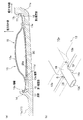
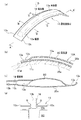
以下に、本発明に係る車両用ホイールおよび副気室部材の実施形態について適宜図面を参照しながら詳細に説明する。参照する図面において、図1は、本実施形態に係る車両用ホイールの斜視図である。図2は、図1の車両用ホイールにタイヤを装着した車輪の要部正面断面図である。図3(a)は、副気室部材を取り付けたウェル部を部分的に拡大した要部正面断面図、図3(b)は、ウェル部の縦壁に形成された切欠き部の斜視図である。
<Structure of vehicle wheel and auxiliary air chamber member>
Hereinafter, embodiments of a vehicle wheel and a sub air chamber member according to the present invention will be described in detail with reference to the drawings as appropriate. In the drawings to be referred to, FIG. 1 is a perspective view of a vehicle wheel according to the present embodiment. FIG. 2 is a front sectional view of a main part of a wheel in which a tire is mounted on the vehicle wheel of FIG. FIG. 3A is a front sectional view of a main part in which the well part to which the auxiliary air chamber member is attached is partially enlarged, and FIG. 3B is a perspective view of a notch part formed in the vertical wall of the well part. It is.
本発明の車両用ホイールは、ウェル部側に副気室部材(ヘルムホルツ・レゾネータ)を嵌め込んで固定したことを主な特徴としている。ここでは、まず車両用ホイールの全体構成について説明した後に、副気室部材の構成について説明する。 The vehicle wheel of the present invention is mainly characterized in that a sub-air chamber member (Helmholtz resonator) is fitted and fixed to the well portion side. Here, after first describing the overall configuration of the vehicle wheel, the configuration of the auxiliary air chamber member will be described.
図1に示すように、本実施形態に係る車両用ホイール10は、タイヤ20(図2参照)を装着するためのリム11と、このリム11を図示しないハブに連結するためのディスク12と、から構成されており、この車両用ホイール10のリム11を構成するウェル部11cの外周面11d(図3(a)参照)上には、副気室部材13が嵌め込まれて固定されている。
As shown in FIG. 1, a
図2に示すように、リム11は、幅方向の両端部に形成されるビードシート部11a,11aと、このビードシート部11a,11aから外側に向けてL字状に屈曲したリムフランジ部11b,11bと、ビードシート部11a,11a間において径方向内側に凹んだウェル部11cと、を有する。
As shown in FIG. 2, the
ビードシート部11aには、タイヤ20のビード部20aが装着される。これにより、リム11とタイヤ20の内周面の間に環状の密閉空間からなるタイヤ空気室MCが形成される。
The
ウェル部11cは、タイヤ20をリム11に組み付けるリム組時に、タイヤ20のビード部20a,20aを落とし込むために設けられている。このウェル部11cの外周面には、縦壁14が立設されている。
The well
縦壁14は、図3(a)に示すように、ウェル部11cの外周面11dから径方向外側に立ち上がる第1の縦壁面15を形成するように外周面11dに立設されている。そして、縦壁14は、外周面11dの周方向に延びて環状となっている。また、ウェル部11cの幅方向内側に形成される側面部11eには、第1の縦壁面15と対向するように第2の縦壁面16が設けられる。なお、本実施形態での縦壁14は、リム11を鋳造する際にウェル部11cと一体に成形される。
As shown in FIG. 3A, the
そして、これらの第1の縦壁面15および第2の縦壁面16には、それぞれ溝部17が形成されている。これらの溝部17,17は、ウェル部11cの外周面11dの周方向に沿って形成されて環状の溝となっている。これらの溝部17,17には、後記する副気室部材13の縁部13eが嵌め込まれることとなる。なお、本実施形態での溝部17,17は、縦壁14および側面部11eのそれぞれに機械加工を施して形成される。
A
また、縦壁14には、図3(a)および(b)に示すように、切欠き部14aが形成されている。この切欠き部14aには、後記する副気室部材13の突出部18(管部材)が嵌め込まれることとなる。なお、本実施形態での切欠き部14aは、リム11を鋳造する際に縦壁14と同時に形成されるか、縦壁14に機械加工を施して形成される。
Further, as shown in FIGS. 3A and 3B, the
ディスク12は、図2に示すように、リム11の車両外側の端部から径方向内側に連続して形成される。リム11とディスク12とは、例えば、アルミニウム合金、マグネシウム合金等の軽量高強度材料等から製造される。なお、これらの材料は限定されるものではなく、スチール(鋼)等から形成されるものであってもよい。また、車両用ホイール10は、スポークホイールであってもよい。
As shown in FIG. 2, the disk 12 is continuously formed radially inward from the end of the
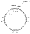
次に、副気室部材13について説明する。ここで参照する図4は、車両用ホイールの側面断面図であって、副気室部材の配置位置を示す図である。図5(a)は、副気室部材の斜視図である。図5(b)は、図5(a)のA−A´断面図であり、A側の部分断面図である。図5(c)は、図5(a)のC−C断面図である。図5(d)は、副気室部材の突出部を図5(a)のD方向から見た部分平面図である。
Next, the auxiliary
副気室部材13は、図4に示すように、ウェル部11cの周方向に沿って配置される一方向に長い部材であって、その内部に副気室SCを有している。そして、本実施形態での副気室部材13は、ウェル部11cの周面に沿って等間隔に4つ配置されている。つまり、本実施形態での車両用ホイール10は、リム11の中心(以下、単に「リム中心」という)を挟んで対向する1対の副気室部材13を2組備えている。
As shown in FIG. 4, the auxiliary
このような副気室部材13は、図5(a)および(b)に示すように、ウェル部11cの外周面11d(図5(b)参照)に沿うように、その長手方向に湾曲している。副気室部材13は、その内部に副気室SCが形成される本体部13aと、この本体部13aからその周囲に延出する板状の縁部13eとを備えている。この縁部13eの肉厚t1は、本体部13aの肉厚t2と同じ厚さとなっている。なお、本実施形態での縁部13eは、肉厚t1や後記する材料を適宜に決定することでバネ弾性を有している。
As shown in FIGS. 5A and 5B, the auxiliary
ここで図5(a)のB−B断面に相当する副気室部材13の断面図を含む図3(a)を参照すると、副気室部材13は、第1の縦壁面15と第2の縦壁面16との間に嵌り込んでウェル部11cの外周面11d上に固定されている。さらに詳しく説明すると、縁部13eは、第1の縦壁面15側と第2の縦壁面16側に延出して各溝部17に嵌り込むとともに、図5(b)に示すように、本体部13aからウェル部11cの外周面11dに沿うように周方向に延出している。ちなみに、副気室部材13は、図3(a)に示すように、本体部13aから第1の縦壁面15側と第2の縦壁面16側にそれぞれ延出する縁部13eの両端縁13c,13cが各溝部17に嵌り込むことで第1の縦壁面15と第2の縦壁面16に係止されている。
Here, referring to FIG. 3A including a cross-sectional view of the auxiliary
そして、図3(a)に示すように、副気室部材13は、両端縁13c,13cの間でウェル部11cの外周面11d側に凸となるように湾曲している。つまり、本体部13aの外周面11d側を構成する底板25aと、この底板25aから延出する縁部13eとは一体となって、いわゆる湾曲部を構成している。ちなみに、副気室部材13は、後記するように、ホイールの回転による遠心力が作用した際に、湾曲部13dが逆に凸となる方向に反転しようとして第1の縦壁面15と第2の縦壁面16とに対する両端縁13c,13cの押圧力を増大させるようになっている。
As shown in FIG. 3A, the auxiliary
また、副気室部材13は、図5(a)および図5(d)に示すように、ホイールの回転方向Xと交差する方向Y(本実施形態では直交する方向)に本体部13aから突出する突出部18を備えている。ちなみに、図5(d)に示すように、突出部18と縁部13eとの間には、隙間Gが形成されている。
Further, as shown in FIGS. 5A and 5D, the auxiliary
この突出部18は、図3(b)に示すように、縦壁14側に延びて、縦壁14に形成された切欠き部14aに嵌り込んでいる。ちなみに、隙間G,Gは、切欠き部14aに突出部18を嵌め込む際に、縁部13eが撓って第1の縦壁面15(図3(a)参照)の溝部17に嵌り易くするものである。本実施形態での突出部18は、図5(c)に示すように、管部材で形成されており、この管部材18の内側には、副気室SCとタイヤ空気室MC(図2参照)とを繋ぐ連通孔13bが形成されている。
As shown in FIG. 3B, the
このような副気室部材13に形成される副気室SCの形状は、特に制限はないが、断面視で扁平形状が好ましく、本実施形態での副気室SCは、図3(a)に示すように、ウェル部11cの径方向に薄い略矩形となっている。
The shape of the sub air chamber SC formed in the sub
副気室SCの容積は、50〜250cc程度が好ましい。副気室SCの容積をこの範囲内に設定することで、副気室部材13は、消音効果を充分に発揮しつつ、その重量の増大を抑制して車両用ホイール10の軽量化を図ることができる。また、周方向の副気室部材13の長さは、リム11の周長と同じ長さを最大として、車両用ホイール10の重量の調整やウェル部11cに対する組付け容易性を考慮して適宜に設定することができる。
The volume of the auxiliary air chamber SC is preferably about 50 to 250 cc. By setting the volume of the sub air chamber SC within this range, the sub
連通孔13bの断面形状は、特に制限はなく、本実施形態では円形となっているが、楕円形、多角形、トンネル形状等のいずれであってもよい。連通孔13bの直径は、断面が円形の場合には、5mm以上が好ましい。また、円形以外の断面形状の連通孔13bは、その断面積で同じ断面積の円形に換算して直径5mm以上のものが好ましい。
The cross-sectional shape of the
連通孔13bの長さは、次の(式1)で示されるヘルムホルツ・レゾネータの共鳴周波数を求める式を満たすように設定される。
The length of the
f0=C/2π×√(S/V(L+α×√S))・・・(式1)
f0(Hz):共鳴周波数
C(m/s):副気室SC内部の音速(=タイヤ空気室MC内部の音速)
V(m3):副気室SCの容積
L(m):連通孔13bの長さ
S(m2):連通孔13bの開口部断面積
α:補正係数
なお、前記共鳴周波数f0は、タイヤ空気室MCの共鳴周波数に合わせられる。この際、図4に示す4つの副気室部材13の共鳴周波数f0は、全て同じに設定してもよいし、違えてもよい。具体的には、タイヤ空気室MCの共鳴周波数に2つの共鳴周波数(f1,f2)が認められる場合に、4つの副気室部材13の共鳴周波数f0を(f1+f2)/2に設定することができる。また、リム中心を挟んで対向する1対の副気室部材13の共鳴周波数f0をf1に設定し、他の1対の副気室部材13の共鳴周波数f0をf2に設定することもできる。
f 0 = C / 2π × √ (S / V (L + α × √S)) (Expression 1)
f 0 (Hz): resonance frequency C (m / s): sound velocity inside the sub-air chamber SC (= sound velocity inside the tire air chamber MC)
V (m 3 ): volume L (m) of the auxiliary air chamber SC: length S (m 2 ) of the
副気室部材13の材料としては、金属、合成樹脂、ゴム等の工業製品に使用される一般的な材料を使用することができる。また、副気室部材13の軽量化や量産性の向上、製造コストの削減、副気室SCの気密性の確保等を考慮すると、軽量で高剛性のブロー成形可能な材料が好ましく、中でも、繰り返しの曲げ疲労にも強いポリプロピレンが好ましい。
As a material of the sub
<第一の実施形態>
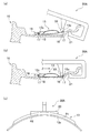
次に、第一の実施形態に係る副気室部材13の車両用ホイール10に対する組付方法について説明する。図6は、第一の実施形態に係る車両用ホイール、副気室部材および組付治具を示す斜視図である。図7は、第一の実施形態に係る組付治具の使用方法を示す図であり、(a)は圧入前を示す断面図、(b)は圧入後を示す断面図、(c)は(b)のZ矢視断面図である。図8(a)〜(d)は、第一の実施形態に係る副気室部材の組付方法を示す図である。
<First embodiment>
Next, a method for assembling the auxiliary
図6および図7に示すように、第一の実施形態に係る組付治具30Aは、リム11の内周面に当接する支点部31と、作業者が操作する力点部32と、副気室部材13を押圧する作用点部33と、を備えている。図7(a)および図7(b)に示すように、車両用ホイール10の第1の縦壁面15の溝部17に、副気室部材13の幅方向一端縁13cを仮止めした状態において、作業者が力点部32を操作すると、副気室部材13の幅方向他端縁13cが車両用ホイール10の第2の縦壁面16の溝部17に圧入され、副気室部材13の両端縁13c,13cが車両用ホイール10の溝部17,17に嵌め込まれる。
As shown in FIGS. 6 and 7, the
ここで、作用点部33は、副気室部材13と同様の材料または副気室部材13よりも柔らかい材料から形成されており、組付時に副気室部材13を傷つけないように構成されている。また、図7(c)に示すように、副気室部材13の端縁13cの上面(組付治具30との当接面)の周方向の曲率r1と、組付治具30の作用点部33の下面(副気室部材13との当接面)の周方向の曲率r2とは、以下の関係を満たしている。
r2≧r1
このように設定することで、副気室部材13の組付時に、作用点部33の周方向端部によって副気室部材13に圧痕が形成されることを防ぐことができる。
Here, the
r2 ≧ r1
By setting in this way, when the auxiliary
第一の実施形態に係る副気室部材13の組付方法においては、まず、図8(a)に示すように、作業者が、車両用ホイール10の第1の縦壁面15の溝部17(図7参照)に、副気室部材13の幅方向一端縁13cの周方向中央部を仮止めする(第1ステップ)。本実施形態では、副気室部材13の突出部18を第1の縦壁面15に形成された切欠き部14aに嵌め込むことによって、容易に仮止めすることができる。
In the assembling method of the auxiliary
続いて、図8(b)に示すように、作業者が組付治具30Aを操作することによって、第2の縦壁面16の溝部17に、副気室部材13の幅方向他端縁13cの周方向中央部を圧入する(第2ステップ)。かかる操作によって、副気室部材13の周方向中央部において、その両端縁13c,13cが車両用ホイール10の溝部17,17に嵌め込まれる。
Subsequently, as shown in FIG. 8B, the operator operates the
続いて、図8(c)(d)に示すように、作業者が組付治具30Aを操作することによって、第2の縦壁面16の溝部17に、副気室部材13の幅方向他端縁13cを周方向中央部から周方向両端に向けて順次圧入する(第3ステップ)。本実施形態では、図8(c)に示すように副気室部材13の幅方向他端縁13cの周方向一端を圧入した後、図8(d)に示すように副気室部材13の幅方向他端縁13cの周方向他端を圧入する。かかる操作によって、副気室部材13の周方向両端において、その両端縁13c,13cが車両用ホイール10の溝部17,17に嵌め込まれる。
Subsequently, as shown in FIGS. 8C and 8D, when the operator operates the assembling
次に、第一の実施形態に係る副気室部材13の組付方法の作用効果について説明する。第一の実施形態に係る副気室部材13は、当該副気室部材13をリム11(ウェル部11c)に固定する際に、図3(a)の端縁13cを第1の縦壁面15と第2の縦壁面16のそれぞれに設けられた溝部17に嵌め込むことで固定される。このとき、縁部13eは、前記したバネ弾性を有しているので、副気室部材13は、第1の縦壁面15と第2の縦壁面16の間に簡単にかつ強固に固定される。
Next, the effect of the assembly method of the sub
第一の実施形態に係る副気室部材13の組付方法によると、最初に副気室部材13の周方向中央部を圧入した後、周方向中央部から周方向両端に向けて順次圧入するので、副気室部材13がずれて組付ができなくなってしまうことを防ぐことができ、副気室部材13を確実かつ効率よく組み付けることが可能となる。
According to the assembling method of the sub
<第二の実施形態>
次に、第二の実施形態に係る副気室部材13の組付方法について、第一の実施形態に係る組付方法との相違点を中心に説明する。図9は、第二の実施形態に係る組付治具の使用方法を示す図であり、(a)は圧入前を示す断面図、(b)は圧入後を示す断面図である。
<Second Embodiment>
Next, the assembling method of the auxiliary
第二の実施形態に係る副気室部材13の組付方法は、組付治具30Aに代えて組付治具30Bを用いる点で、第一の実施形態に係る組付方法と相違する。第二の実施形態に係る組付治具30Bは、リム11の内周面に当接する支点部31に代えて、車両用ホイール10を固定する台座等に回動可能に設けられた支点部34を備えている。かかる組付治具30Bを用いる第二の実施形態に係る副気室部材13の組付方法においても、第一の実施形態にかかる組付方法と同様に、副気室部材13を確実かつ効率よく組み付けることができる。
The assembly method of the sub
<第三の実施形態>
次に、第三の実施形態に係る副気室部材13の組付方法について、第一の実施形態との相違点を中心に説明する。図10は、第三の実施形態に係る組付治具の使用方法を示す図である。
<Third embodiment>
Next, a method for assembling the auxiliary
第三の実施形態に係る副気室部材13の組付方法は、組付治具30Aに代えて組付治具30Cを用いる点で、第一の実施形態に係る組付方法と相違する。第三の実施形態に係る組付治具30Cは、一対のローラ部材35a,35bを備えている。一対のローラ部材35a,35は、副気室部材13の幅方向他端縁13c上を周方向に転動しながら押圧することができる。かかる組付治具30Cを用いると、副気室部材13の幅方向他端縁13cの周方向中央部を第2の縦壁面16の溝部17(図3(a)参照)に圧入した後、副気室部材13の幅方向他端縁13cを周方向中央部から周方向両端に向けて、両端の圧入量がほぼ均等となるように順次圧入することができる。かかる組付治具30Cを用いた組付方法は、作業者の手動によるものであってもよく、組付治具30Cを駆動する駆動装置と、当該駆動装置を制御する制御装置と、によって自動化されたものであってもよい。
The assembly method of the auxiliary
以上、本実施形態について説明したが、本発明は前記実施形態に限定されず、種々の形態で実施することができる。例えば、第一の実施形態に係る組付治具30Aを複数(例えば、3個)用意して副気室部材13上に配置し、周方向中央部の組付治具30Aから周方向両端の組付治具30Aへと順次組付治具30Aを使用することによって副気室部材13を組み付けることもできる。
As mentioned above, although this embodiment was described, this invention is not limited to the said embodiment, It can implement with a various form. For example, a plurality of (for example, three) assembly jigs 30A according to the first embodiment are prepared and arranged on the auxiliary
また、組付治具30A,30Bの作用点部33の全長は、当該組付治具30A,30Bによる圧入作業の回数に応じて適宜設計変更可能である。また、周方向両端に向けての圧入作業が複数回必要な場合には、周方向一端側→周方向他端側→周方向一端側→周方向他端側→・・・と両端側のそれぞれに対して圧入作業を交互に行いつつ周方向両端に向けて圧入作業を行う構成とすることができる。
The total length of the
10 車両用ホイール
13 副気室部材
13b 連通孔
13c 端縁
14a 切欠き部
15 第1の縦壁面
16 第2の縦壁面
17 溝部
18 突出部(管部材)
MC タイヤ空気室
SC 副気室
DESCRIPTION OF
MC tire air chamber SC secondary air chamber
Claims (2)
前記一対の縦壁面の一方の溝部に、前記副気室部材の幅方向一端縁を配置するステップと、
前記一対の縦壁面の他方の溝部に、前記副気室部材の幅方向他端縁を圧入するステップと、
を含むことを特徴とする副気室部材の組付方法。 When a sub air chamber member having a sub air chamber communicating with the tire air chamber is assembled to the vehicle wheel, the sub air chamber member is formed to rise radially outward from the outer peripheral surface of the vehicle wheel and extend in the circumferential direction of the outer peripheral surface. The auxiliary air chamber member is assembled to the vehicle wheel by fitting both end edges in the width direction of the auxiliary air chamber member into the grooves of a pair of vertical wall surfaces facing each other. And
Disposing one end edge in the width direction of the auxiliary air chamber member in one groove of the pair of vertical wall surfaces;
Press-fitting the other end in the width direction of the auxiliary air chamber member into the other groove of the pair of vertical wall surfaces;
A method of assembling the auxiliary air chamber member, comprising:
前記一対の縦壁面の他方の溝部に、前記副気室部材の幅方向他端縁の一部を圧入するステップと、
前記一対の縦壁面の他方の溝部に、前記副気室部材の幅方向他端縁を圧入された前記一部から周方向に向けて順次圧入するステップと、
を含むことを特徴とする請求項1に記載の副気室部材の組付方法。 The step of press-fitting the other end edge in the width direction of the auxiliary air chamber member includes:
Press-fitting a part of the other edge in the width direction of the auxiliary air chamber member into the other groove of the pair of vertical wall surfaces;
A step of sequentially press-fitting the other end edge in the width direction of the auxiliary air chamber member into the other groove portion of the pair of vertical wall surfaces from the part pressed into the circumferential direction;
The method of assembling the auxiliary air chamber member according to claim 1, comprising:
Priority Applications (1)
| Application Number | Priority Date | Filing Date | Title |
|---|---|---|---|
| JP2012098596A JP5389974B2 (en) | 2012-04-24 | 2012-04-24 | Assembly method of auxiliary air chamber members |
Applications Claiming Priority (1)
| Application Number | Priority Date | Filing Date | Title |
|---|---|---|---|
| JP2012098596A JP5389974B2 (en) | 2012-04-24 | 2012-04-24 | Assembly method of auxiliary air chamber members |
Related Parent Applications (1)
| Application Number | Title | Priority Date | Filing Date |
|---|---|---|---|
| JP2008268121A Division JP4986969B2 (en) | 2008-10-17 | 2008-10-17 | Assembly method of auxiliary air chamber members |
Publications (2)
| Publication Number | Publication Date |
|---|---|
| JP2012158332A true JP2012158332A (en) | 2012-08-23 |
| JP5389974B2 JP5389974B2 (en) | 2014-01-15 |
Family
ID=46839207
Family Applications (1)
| Application Number | Title | Priority Date | Filing Date |
|---|---|---|---|
| JP2012098596A Active JP5389974B2 (en) | 2012-04-24 | 2012-04-24 | Assembly method of auxiliary air chamber members |
Country Status (1)
| Country | Link |
|---|---|
| JP (1) | JP5389974B2 (en) |
Cited By (3)
| Publication number | Priority date | Publication date | Assignee | Title |
|---|---|---|---|---|
| EP2962866A4 (en) * | 2013-02-28 | 2017-08-30 | Honda Motor Co., Ltd. | Vehicle wheel |
| EP2962867A4 (en) * | 2013-02-28 | 2017-08-30 | Honda Motor Co., Ltd. | Vehicle wheel |
| DE102016214206A1 (en) * | 2016-08-02 | 2018-02-08 | Audi Ag | Device for eradicating vibration resonances |
Citations (4)
| Publication number | Priority date | Publication date | Assignee | Title |
|---|---|---|---|---|
| JP2002178727A (en) * | 2000-12-08 | 2002-06-26 | Bridgestone Corp | Core body for tires, rim wheel with core and tire and rim assembly |
| JP2004306760A (en) * | 2003-04-07 | 2004-11-04 | Honda Motor Co Ltd | Resonance preventing belt for wheel |
| JP2007196702A (en) * | 2006-01-23 | 2007-08-09 | Bridgestone Corp | Sensor mounting structure, vehicle wheel and wheel/tire assembly |
| EP1892123A2 (en) * | 2006-08-24 | 2008-02-27 | Bayerische Motoren Werke Aktiengesellschaft | Tubeless spoked wheel for two-wheeled vehicles, in particular for motor cycles |
-
2012
- 2012-04-24 JP JP2012098596A patent/JP5389974B2/en active Active
Patent Citations (4)
| Publication number | Priority date | Publication date | Assignee | Title |
|---|---|---|---|---|
| JP2002178727A (en) * | 2000-12-08 | 2002-06-26 | Bridgestone Corp | Core body for tires, rim wheel with core and tire and rim assembly |
| JP2004306760A (en) * | 2003-04-07 | 2004-11-04 | Honda Motor Co Ltd | Resonance preventing belt for wheel |
| JP2007196702A (en) * | 2006-01-23 | 2007-08-09 | Bridgestone Corp | Sensor mounting structure, vehicle wheel and wheel/tire assembly |
| EP1892123A2 (en) * | 2006-08-24 | 2008-02-27 | Bayerische Motoren Werke Aktiengesellschaft | Tubeless spoked wheel for two-wheeled vehicles, in particular for motor cycles |
Cited By (3)
| Publication number | Priority date | Publication date | Assignee | Title |
|---|---|---|---|---|
| EP2962866A4 (en) * | 2013-02-28 | 2017-08-30 | Honda Motor Co., Ltd. | Vehicle wheel |
| EP2962867A4 (en) * | 2013-02-28 | 2017-08-30 | Honda Motor Co., Ltd. | Vehicle wheel |
| DE102016214206A1 (en) * | 2016-08-02 | 2018-02-08 | Audi Ag | Device for eradicating vibration resonances |
Also Published As
| Publication number | Publication date |
|---|---|
| JP5389974B2 (en) | 2014-01-15 |
Similar Documents
| Publication | Publication Date | Title |
|---|---|---|
| JP4551422B2 (en) | Vehicle wheel | |
| JP4523959B2 (en) | Vehicle wheel | |
| US7896044B2 (en) | Vehicle wheel having a sub air chamber | |
| US8181685B2 (en) | Vehicle wheel | |
| JP4665011B2 (en) | Vehicle wheel | |
| JP5091749B2 (en) | Vehicle wheel | |
| US9649892B2 (en) | Wheel for vehicle | |
| US9694626B2 (en) | Vehicle wheel | |
| US9399372B2 (en) | Vehicle wheel | |
| US10011148B2 (en) | Vehicle wheel | |
| JP4834711B2 (en) | Vehicle wheel | |
| JP4546948B2 (en) | Vehicle wheel | |
| US20160001596A1 (en) | Vehicle wheel | |
| JP2010095103A (en) | Vehicle wheel | |
| JP2010052700A (en) | Wheel for vehicle | |
| JP2010095147A (en) | Vehicle wheel | |
| JPWO2016143533A1 (en) | Vehicle wheel | |
| JP5389974B2 (en) | Assembly method of auxiliary air chamber members | |
| JP4986969B2 (en) | Assembly method of auxiliary air chamber members | |
| JP2019196045A (en) | Vehicle wheel | |
| JP2010095104A (en) | Vehicle wheel | |
| JP5091748B2 (en) | Vehicle wheel | |
| JP5091829B2 (en) | Vehicle wheel | |
| JP2008179307A (en) | Vehicle wheel | |
| JP2015168404A (en) | resonator |
Legal Events
| Date | Code | Title | Description |
|---|---|---|---|
| A131 | Notification of reasons for refusal |
Free format text: JAPANESE INTERMEDIATE CODE: A131 Effective date: 20130528 |
|
| A977 | Report on retrieval |
Free format text: JAPANESE INTERMEDIATE CODE: A971007 Effective date: 20130531 |
|
| A521 | Written amendment |
Free format text: JAPANESE INTERMEDIATE CODE: A523 Effective date: 20130729 |
|
| TRDD | Decision of grant or rejection written | ||
| A01 | Written decision to grant a patent or to grant a registration (utility model) |
Free format text: JAPANESE INTERMEDIATE CODE: A01 Effective date: 20131001 |
|
| A61 | First payment of annual fees (during grant procedure) |
Free format text: JAPANESE INTERMEDIATE CODE: A61 Effective date: 20131009 |
|
| R150 | Certificate of patent or registration of utility model |
Ref document number: 5389974 Country of ref document: JP Free format text: JAPANESE INTERMEDIATE CODE: R150 Free format text: JAPANESE INTERMEDIATE CODE: R150 |
|
| R250 | Receipt of annual fees |
Free format text: JAPANESE INTERMEDIATE CODE: R250 |