JP2012158214A - Brake device for vehicle - Google Patents
Brake device for vehicle Download PDFInfo
- Publication number
- JP2012158214A JP2012158214A JP2011017716A JP2011017716A JP2012158214A JP 2012158214 A JP2012158214 A JP 2012158214A JP 2011017716 A JP2011017716 A JP 2011017716A JP 2011017716 A JP2011017716 A JP 2011017716A JP 2012158214 A JP2012158214 A JP 2012158214A
- Authority
- JP
- Japan
- Prior art keywords
- motor
- cylinder
- brake
- slave cylinder
- idling
- Prior art date
- Legal status (The legal status is an assumption and is not a legal conclusion. Google has not performed a legal analysis and makes no representation as to the accuracy of the status listed.)
- Granted
Links
Images


Classifications
-
- B—PERFORMING OPERATIONS; TRANSPORTING
- B60—VEHICLES IN GENERAL
- B60T—VEHICLE BRAKE CONTROL SYSTEMS OR PARTS THEREOF; BRAKE CONTROL SYSTEMS OR PARTS THEREOF, IN GENERAL; ARRANGEMENT OF BRAKING ELEMENTS ON VEHICLES IN GENERAL; PORTABLE DEVICES FOR PREVENTING UNWANTED MOVEMENT OF VEHICLES; VEHICLE MODIFICATIONS TO FACILITATE COOLING OF BRAKES
- B60T8/00—Arrangements for adjusting wheel-braking force to meet varying vehicular or ground-surface conditions, e.g. limiting or varying distribution of braking force
- B60T8/32—Arrangements for adjusting wheel-braking force to meet varying vehicular or ground-surface conditions, e.g. limiting or varying distribution of braking force responsive to a speed condition, e.g. acceleration or deceleration
- B60T8/34—Arrangements for adjusting wheel-braking force to meet varying vehicular or ground-surface conditions, e.g. limiting or varying distribution of braking force responsive to a speed condition, e.g. acceleration or deceleration having a fluid pressure regulator responsive to a speed condition
- B60T8/40—Arrangements for adjusting wheel-braking force to meet varying vehicular or ground-surface conditions, e.g. limiting or varying distribution of braking force responsive to a speed condition, e.g. acceleration or deceleration having a fluid pressure regulator responsive to a speed condition comprising an additional fluid circuit including fluid pressurising means for modifying the pressure of the braking fluid, e.g. including wheel driven pumps for detecting a speed condition, or pumps which are controlled by means independent of the braking system
- B60T8/4072—Systems in which a driver input signal is used as a control signal for the additional fluid circuit which is normally used for braking
- B60T8/4081—Systems with stroke simulating devices for driver input
-
- B—PERFORMING OPERATIONS; TRANSPORTING
- B60—VEHICLES IN GENERAL
- B60T—VEHICLE BRAKE CONTROL SYSTEMS OR PARTS THEREOF; BRAKE CONTROL SYSTEMS OR PARTS THEREOF, IN GENERAL; ARRANGEMENT OF BRAKING ELEMENTS ON VEHICLES IN GENERAL; PORTABLE DEVICES FOR PREVENTING UNWANTED MOVEMENT OF VEHICLES; VEHICLE MODIFICATIONS TO FACILITATE COOLING OF BRAKES
- B60T15/00—Construction arrangement, or operation of valves incorporated in power brake systems and not covered by groups B60T11/00 or B60T13/00
-
- B—PERFORMING OPERATIONS; TRANSPORTING
- B60—VEHICLES IN GENERAL
- B60T—VEHICLE BRAKE CONTROL SYSTEMS OR PARTS THEREOF; BRAKE CONTROL SYSTEMS OR PARTS THEREOF, IN GENERAL; ARRANGEMENT OF BRAKING ELEMENTS ON VEHICLES IN GENERAL; PORTABLE DEVICES FOR PREVENTING UNWANTED MOVEMENT OF VEHICLES; VEHICLE MODIFICATIONS TO FACILITATE COOLING OF BRAKES
- B60T13/00—Transmitting braking action from initiating means to ultimate brake actuator with power assistance or drive; Brake systems incorporating such transmitting means, e.g. air-pressure brake systems
- B60T13/10—Transmitting braking action from initiating means to ultimate brake actuator with power assistance or drive; Brake systems incorporating such transmitting means, e.g. air-pressure brake systems with fluid assistance, drive, or release
- B60T13/12—Transmitting braking action from initiating means to ultimate brake actuator with power assistance or drive; Brake systems incorporating such transmitting means, e.g. air-pressure brake systems with fluid assistance, drive, or release the fluid being liquid
- B60T13/14—Transmitting braking action from initiating means to ultimate brake actuator with power assistance or drive; Brake systems incorporating such transmitting means, e.g. air-pressure brake systems with fluid assistance, drive, or release the fluid being liquid using accumulators or reservoirs fed by pumps
- B60T13/142—Systems with master cylinder
- B60T13/145—Master cylinder integrated or hydraulically coupled with booster
- B60T13/146—Part of the system directly actuated by booster pressure
-
- B—PERFORMING OPERATIONS; TRANSPORTING
- B60—VEHICLES IN GENERAL
- B60T—VEHICLE BRAKE CONTROL SYSTEMS OR PARTS THEREOF; BRAKE CONTROL SYSTEMS OR PARTS THEREOF, IN GENERAL; ARRANGEMENT OF BRAKING ELEMENTS ON VEHICLES IN GENERAL; PORTABLE DEVICES FOR PREVENTING UNWANTED MOVEMENT OF VEHICLES; VEHICLE MODIFICATIONS TO FACILITATE COOLING OF BRAKES
- B60T13/00—Transmitting braking action from initiating means to ultimate brake actuator with power assistance or drive; Brake systems incorporating such transmitting means, e.g. air-pressure brake systems
- B60T13/10—Transmitting braking action from initiating means to ultimate brake actuator with power assistance or drive; Brake systems incorporating such transmitting means, e.g. air-pressure brake systems with fluid assistance, drive, or release
- B60T13/66—Electrical control in fluid-pressure brake systems
- B60T13/662—Electrical control in fluid-pressure brake systems characterised by specified functions of the control system components
-
- B—PERFORMING OPERATIONS; TRANSPORTING
- B60—VEHICLES IN GENERAL
- B60T—VEHICLE BRAKE CONTROL SYSTEMS OR PARTS THEREOF; BRAKE CONTROL SYSTEMS OR PARTS THEREOF, IN GENERAL; ARRANGEMENT OF BRAKING ELEMENTS ON VEHICLES IN GENERAL; PORTABLE DEVICES FOR PREVENTING UNWANTED MOVEMENT OF VEHICLES; VEHICLE MODIFICATIONS TO FACILITATE COOLING OF BRAKES
- B60T13/00—Transmitting braking action from initiating means to ultimate brake actuator with power assistance or drive; Brake systems incorporating such transmitting means, e.g. air-pressure brake systems
- B60T13/74—Transmitting braking action from initiating means to ultimate brake actuator with power assistance or drive; Brake systems incorporating such transmitting means, e.g. air-pressure brake systems with electrical assistance or drive
- B60T13/745—Transmitting braking action from initiating means to ultimate brake actuator with power assistance or drive; Brake systems incorporating such transmitting means, e.g. air-pressure brake systems with electrical assistance or drive acting on a hydraulic system, e.g. a master cylinder
-
- B—PERFORMING OPERATIONS; TRANSPORTING
- B60—VEHICLES IN GENERAL
- B60T—VEHICLE BRAKE CONTROL SYSTEMS OR PARTS THEREOF; BRAKE CONTROL SYSTEMS OR PARTS THEREOF, IN GENERAL; ARRANGEMENT OF BRAKING ELEMENTS ON VEHICLES IN GENERAL; PORTABLE DEVICES FOR PREVENTING UNWANTED MOVEMENT OF VEHICLES; VEHICLE MODIFICATIONS TO FACILITATE COOLING OF BRAKES
- B60T17/00—Component parts, details, or accessories of power brake systems not covered by groups B60T8/00, B60T13/00 or B60T15/00, or presenting other characteristic features
- B60T17/18—Safety devices; Monitoring
- B60T17/22—Devices for monitoring or checking brake systems; Signal devices
- B60T17/221—Procedure or apparatus for checking or keeping in a correct functioning condition of brake systems
- B60T17/222—Procedure or apparatus for checking or keeping in a correct functioning condition of brake systems by filling or bleeding of hydraulic systems
- B60T17/223—Devices for pressurising brake systems acting on pedal
-
- B—PERFORMING OPERATIONS; TRANSPORTING
- B60—VEHICLES IN GENERAL
- B60T—VEHICLE BRAKE CONTROL SYSTEMS OR PARTS THEREOF; BRAKE CONTROL SYSTEMS OR PARTS THEREOF, IN GENERAL; ARRANGEMENT OF BRAKING ELEMENTS ON VEHICLES IN GENERAL; PORTABLE DEVICES FOR PREVENTING UNWANTED MOVEMENT OF VEHICLES; VEHICLE MODIFICATIONS TO FACILITATE COOLING OF BRAKES
- B60T7/00—Brake-action initiating means
- B60T7/02—Brake-action initiating means for personal initiation
- B60T7/04—Brake-action initiating means for personal initiation foot actuated
- B60T7/042—Brake-action initiating means for personal initiation foot actuated by electrical means, e.g. using travel or force sensors
-
- B—PERFORMING OPERATIONS; TRANSPORTING
- B60—VEHICLES IN GENERAL
- B60L—PROPULSION OF ELECTRICALLY-PROPELLED VEHICLES; SUPPLYING ELECTRIC POWER FOR AUXILIARY EQUIPMENT OF ELECTRICALLY-PROPELLED VEHICLES; ELECTRODYNAMIC BRAKE SYSTEMS FOR VEHICLES IN GENERAL; MAGNETIC SUSPENSION OR LEVITATION FOR VEHICLES; MONITORING OPERATING VARIABLES OF ELECTRICALLY-PROPELLED VEHICLES; ELECTRIC SAFETY DEVICES FOR ELECTRICALLY-PROPELLED VEHICLES
- B60L2240/00—Control parameters of input or output; Target parameters
- B60L2240/40—Drive Train control parameters
- B60L2240/42—Drive Train control parameters related to electric machines
- B60L2240/421—Speed
-
- B—PERFORMING OPERATIONS; TRANSPORTING
- B60—VEHICLES IN GENERAL
- B60L—PROPULSION OF ELECTRICALLY-PROPELLED VEHICLES; SUPPLYING ELECTRIC POWER FOR AUXILIARY EQUIPMENT OF ELECTRICALLY-PROPELLED VEHICLES; ELECTRODYNAMIC BRAKE SYSTEMS FOR VEHICLES IN GENERAL; MAGNETIC SUSPENSION OR LEVITATION FOR VEHICLES; MONITORING OPERATING VARIABLES OF ELECTRICALLY-PROPELLED VEHICLES; ELECTRIC SAFETY DEVICES FOR ELECTRICALLY-PROPELLED VEHICLES
- B60L2240/00—Control parameters of input or output; Target parameters
- B60L2240/40—Drive Train control parameters
- B60L2240/46—Drive Train control parameters related to wheels
- B60L2240/461—Speed
-
- B—PERFORMING OPERATIONS; TRANSPORTING
- B60—VEHICLES IN GENERAL
- B60L—PROPULSION OF ELECTRICALLY-PROPELLED VEHICLES; SUPPLYING ELECTRIC POWER FOR AUXILIARY EQUIPMENT OF ELECTRICALLY-PROPELLED VEHICLES; ELECTRODYNAMIC BRAKE SYSTEMS FOR VEHICLES IN GENERAL; MAGNETIC SUSPENSION OR LEVITATION FOR VEHICLES; MONITORING OPERATING VARIABLES OF ELECTRICALLY-PROPELLED VEHICLES; ELECTRIC SAFETY DEVICES FOR ELECTRICALLY-PROPELLED VEHICLES
- B60L2250/00—Driver interactions
- B60L2250/26—Driver interactions by pedal actuation
-
- B—PERFORMING OPERATIONS; TRANSPORTING
- B60—VEHICLES IN GENERAL
- B60T—VEHICLE BRAKE CONTROL SYSTEMS OR PARTS THEREOF; BRAKE CONTROL SYSTEMS OR PARTS THEREOF, IN GENERAL; ARRANGEMENT OF BRAKING ELEMENTS ON VEHICLES IN GENERAL; PORTABLE DEVICES FOR PREVENTING UNWANTED MOVEMENT OF VEHICLES; VEHICLE MODIFICATIONS TO FACILITATE COOLING OF BRAKES
- B60T2270/00—Further aspects of brake control systems not otherwise provided for
- B60T2270/40—Failsafe aspects of brake control systems
- B60T2270/402—Back-up
-
- B—PERFORMING OPERATIONS; TRANSPORTING
- B60—VEHICLES IN GENERAL
- B60T—VEHICLE BRAKE CONTROL SYSTEMS OR PARTS THEREOF; BRAKE CONTROL SYSTEMS OR PARTS THEREOF, IN GENERAL; ARRANGEMENT OF BRAKING ELEMENTS ON VEHICLES IN GENERAL; PORTABLE DEVICES FOR PREVENTING UNWANTED MOVEMENT OF VEHICLES; VEHICLE MODIFICATIONS TO FACILITATE COOLING OF BRAKES
- B60T2270/00—Further aspects of brake control systems not otherwise provided for
- B60T2270/82—Brake-by-Wire, EHB
-
- Y—GENERAL TAGGING OF NEW TECHNOLOGICAL DEVELOPMENTS; GENERAL TAGGING OF CROSS-SECTIONAL TECHNOLOGIES SPANNING OVER SEVERAL SECTIONS OF THE IPC; TECHNICAL SUBJECTS COVERED BY FORMER USPC CROSS-REFERENCE ART COLLECTIONS [XRACs] AND DIGESTS
- Y02—TECHNOLOGIES OR APPLICATIONS FOR MITIGATION OR ADAPTATION AGAINST CLIMATE CHANGE
- Y02T—CLIMATE CHANGE MITIGATION TECHNOLOGIES RELATED TO TRANSPORTATION
- Y02T10/00—Road transport of goods or passengers
- Y02T10/60—Other road transportation technologies with climate change mitigation effect
- Y02T10/64—Electric machine technologies in electromobility
Abstract
Description
本発明は、運転者によるブレーキペダルの操作量を電気信号に変換してスレーブシリンダを作動させ、このスレーブシリンダが発生するブレーキ液圧でホイールシリンダを作動させる、いわゆるBBW(ブレーキ・バイ・ワイヤ)式ブレーキ装置に関する。 The present invention converts a brake pedal operation amount by a driver into an electric signal to operate a slave cylinder, and operates a wheel cylinder with a brake hydraulic pressure generated by the slave cylinder, so-called BBW (brake-by-wire). The present invention relates to a type brake device.
かかるBBW式ブレーキ装置において、ブレーキペダルの操作量に応じた電気信号で作動してブレーキ液圧を発生するスレーブシリンダを、シリンダと、シリンダに摺動自在に嵌合するピストンと、モータと、モータの回転を減速してピストンの往復動に変換する減速機構とで構成したものが、下記特許文献1により公知である。 In such a BBW brake device, a slave cylinder that generates brake fluid pressure by operating with an electric signal corresponding to an operation amount of a brake pedal, a cylinder, a piston that is slidably fitted to the cylinder, a motor, and a motor Japanese Patent Application Laid-Open No. 2004-151867 discloses a structure constituted by a speed reducing mechanism that decelerates the rotation of the shaft and converts it into a reciprocating motion of a piston.
ところで、スレーブシリンダのハウジングからモータが脱落したり、減速機構のギヤに破損や噛合不良が発生したりしてモータが空転すると、モータは回転するにも関わらずにスレーブシリンダがブレーキ液圧を発生できなくなる可能性がある。このような場合、モータが回転するために制御装置は異常状態を判定できず、スレーブシリンダが発生したブレーキ液圧による制動からマスタシリンダが発生したブレーキ液圧による制動への切換えが遅れ、運転者に違和感を与える可能性がある。 By the way, if the motor falls off from the housing of the slave cylinder, the gear of the speed reduction mechanism is damaged, or the meshing failure occurs, the slave cylinder generates brake fluid pressure even though the motor rotates. It may not be possible. In such a case, since the motor rotates, the control device cannot determine the abnormal state, and the switching from the braking by the brake fluid pressure generated by the slave cylinder to the braking by the brake fluid pressure generated by the master cylinder is delayed. May give a sense of incongruity.
本発明は前述の事情に鑑みてなされたもので、スレーブシリンダのモータが空転したときにマスタシリンダが発生したブレーキ液圧によるバックアップが速やかに行えるようにすることを目的とする。 The present invention has been made in view of the above-described circumstances, and an object of the present invention is to enable quick backup by brake fluid pressure generated by a master cylinder when a motor of a slave cylinder idles.
上記目的を達成するために、請求項1に記載された発明によれば、ブレーキペダルの操作によってブレーキ液圧を発生するマスタシリンダと、前記ブレーキペダルの操作に反力を付与するストロークシミュレータと、車輪を制動するホイールシリンダと、前記マスタシリンダおよび前記ホイールシリンダを接続する液路を遮断可能なマスタカットバルブと、前記マスタカットバルブおよび前記ホイールシリンダ間に配置されて前記ブレーキペダルの操作に応じたブレーキ液圧を発生するスレーブシリンダと、前記ブレーキペダルが操作されたときに前記ストロークシミュレータを作動可能にした状態で前記マスタカットバルブを閉弁して前記スレーブシリンダを作動させる制御手段と、前記モータの空転を検出する空転検出手段とを備え、前記空転検出手段が前記スレーブシリンダのモータの空転を検出したときに、前記制御手段は前記マスタカットバルブを開弁して前記マスタシリンダが発生するブレーキ液圧で前記ホイールシリンダを作動させることを特徴とする車両用ブレーキ装置が提案される。
In order to achieve the above object, according to the invention described in
また請求項2に記載された発明によれば、請求項1の構成に加えて、前記空転検出手段は、前記モータの回転数が前記スレーブシリンダのストロークに応じて設定される基準値よりも大きいときに該モータの空転を検出することを特徴とする車両用ブレーキ装置が提案される。 According to the second aspect of the present invention, in addition to the configuration of the first aspect, the idling detection means is configured such that the rotational speed of the motor is larger than a reference value set according to the stroke of the slave cylinder. A vehicular brake device is sometimes proposed which detects idling of the motor.
また請求項3に記載された発明によれば、請求項1の構成に加えて、前記空転検出手段は、前記モータの指示電圧値とトルク電流値とを比較することで該モータの空転を検出することを特徴とする車両用ブレーキ装置が提案される。 According to a third aspect of the invention, in addition to the configuration of the first aspect, the idling detection means detects idling of the motor by comparing the command voltage value of the motor with a torque current value. A vehicle brake device is proposed.
また請求項4に記載された発明によれば、請求項1の構成に加えて、前記マスタカットバルブを開弁するまでの間、前記スレーブシリンダに代わって車輪を制動する補助制動手段を備えることを特徴とする車両用ブレーキ装置が提案される。
According to the invention described in claim 4, in addition to the configuration of
尚、実施の形態の第1、第2マスタカットバルブ32,33は本発明のマスタカットバルブに対応し、実施の形態の電子制御ユニットUは本発明の制御手段に対応し、実施の形態の駆動モータは本発明の補助制動手段に対応する。
The first and second
請求項1の構成によれば、正常時には、マスタカットバルブが閉弁してマスタシリンダおよびスレーブシリンダを接続する液路が遮断された状態で、運転者によるブレーキペダルの操作量に応じてスレーブシリンダが駆動され、スレーブシリンダが発生するブレーキ液圧でホイールシリンダが作動するとともに、ストロークシミュレータによってブレーキペダルの操作に反力が付与される。スレーブシリンダが作動不能になる異常時には、ブレーキペダルによって作動するマスタシリンダが発生するブレーキ液圧でホイールシリンダが作動する。空転検出手段がスレーブシリンダのモータの空転を検出すると、制御手段がマスタカットバルブを開弁してマスタシリンダが発生するブレーキ液圧でホイールシリンダを作動させるので、作動不能になったスレーブシリンダをマスタシリンダで速やかにバックアップすることができる。
According to the configuration of
また請求項2の構成によれば、空転検出手段は、モータの回転速度がスレーブシリンダのストロークに応じて設定される基準値よりも大きいときにモータの空転を検出するので、モータの空転を確実かつ速やかに検出することができる。 According to the second aspect of the present invention, the idling detection means detects the idling of the motor when the rotation speed of the motor is larger than the reference value set according to the stroke of the slave cylinder. And it can detect promptly.
また請求項3の構成によれば、空転検出手段は、モータの指示電圧値とトルク電流値とを比較することでモータの空転するので、モータの空転を確実かつ速やかに検出することができる。 According to the third aspect of the present invention, the idling detection means compares the instruction voltage value of the motor with the torque current value, and the idling of the motor can be detected reliably and promptly.
また請求項4の構成によれば、マスタカットバルブを開弁するまでの間、補助制動手段がスレーブシリンダに代わって車輪を制動するので、スレーブシリンダによる制動からマスタシリンダによる制動への切り換えに伴う減速度の低下量を最小限に抑えることができる。 According to the fourth aspect of the present invention, since the auxiliary braking means brakes the wheel instead of the slave cylinder until the master cut valve is opened, it is accompanied by switching from braking by the slave cylinder to braking by the master cylinder. The amount of decrease in deceleration can be minimized.
以下、図1〜図7に基づいて本発明の第1の実施の形態を説明する。 Hereinafter, a first embodiment of the present invention will be described with reference to FIGS.
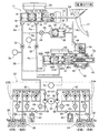
図1に示すように、タンデム型のマスタシリンダ11は、運転者が操作するブレーキペダル12にプッシュロッド13を介して接続された第1ピストン14と、その前方に配置された第2ピストン15とを備えており、第1ピストン14および第2ピストン15間にリターンスプリング16が収納された第1液圧室17が区画され、第2ピストン15の前方にリターンスプリング18が収納された第2液圧室19が区画される。リザーバ20に連通可能な第1液圧室17および第2液圧室19はそれぞれ第1出力ポート21および第2出力ポート22を備えており、第1出力ポート21は液路Pa,Pb、VSA(ビークル・スタビリティ・アシスト)装置23および液路Pc,Pdを介して、例えば左右の後輪のディスクブレーキ装置24,25のホイールシリンダ26,27(第1系統)に接続されるとともに、第2出力ポート22は液路Qa,Qb、VSA装置23および液路Qc,Qdを介して、例えば左右の前輪のディスクブレーキ装置28,29のホイールシリンダ30,31(第2系統)に接続される。
As shown in FIG. 1, a tandem master cylinder 11 includes a
尚、本明細書で、液路Pa〜Pdおよび液路Qa〜Qdの上流側とはマスタシリンダ11側を意味し、下流側とはホイールシリンダ26,27;30,31側を意味するものとする。
In the present specification, the upstream side of the fluid paths Pa to Pd and the fluid paths Qa to Qd means the master cylinder 11 side, and the downstream side means the
液路Pa,Pb間に常開型電磁弁である第1マスタカットバルブ32が配置され、液路Qa,Qb間に常開型電磁弁である第2マスタカットバルブ33が配置される。第2マスタカットバルブ33の上流側の液路Qaから分岐する供給側液路Ra,Rbは、常閉型電磁弁であるシミュレータバルブ34を介してストロークシミュレータ35に接続される。ストロークシミュレータ35は、シリンダ36にスプリング37で付勢されたピストン38を摺動自在に嵌合させたもので、ピストン38の反スプリング37側に形成された液圧室39が供給側液路Rbに連通する。
A first
第1、第2マスタカットバルブ32,33の下流側の液路Pbおよび液路Qbにタンデム型のスレーブシリンダ42が接続される。スレーブシリンダ42を作動させるアクチュエータ43は、モータ44の回転をギヤ列45を介してボールねじ機構46に伝達する。スレーブシリンダ42のシリンダ本体47には、ボールねじ機構46により駆動される第1ピストン48Aと、その前方に位置する第2ピストン48Bとが摺動自在に嵌合しており、第1ピストン48Aおよび第2ピストン48B間にリターンスプリング49Aが収納された第1液圧室50Aが区画され、第2ピストン48Bの前方にリターンスプリング49Bが収納された第2液圧室50Bが区画される。アクチュエータ43のボールねじ機構46で第1、第2ピストン48A,48Bを前進方向に駆動すると、第1、第2液圧室50A,50Bに発生したブレーキ液圧が第1、第2出力ポート51A,51Bを介して液路Pb,Qbに伝達される。
A
スレーブシリンダ42のリザーバ69とマスタシリンダ11のリザーバ20とが排出側液路Rcで接続されており、ストロークシミュレータ35のピストン38の背室70が排出側液路Rdを介して排出側液路Rcの中間部に接続される。
The
VSA装置23の構造は周知のもので、左右の後輪のディスクブレーキ装置24,25の第1系統を制御する第1ブレーキアクチュエータ23Aと、左右の前輪のディスクブレーキ装置28,29の第2系統を制御する第2ブレーキアクチュエータ23Bとに同じ構造のものが設けられる。
The structure of the VSA
以下、その代表として左右の後輪のディスクブレーキ装置24,25の第1系統の第1ブレーキアクチュエータ23Aについて説明する。
As a representative example, the
第1ブレーキアクチュエータ23Aは、上流側に位置する第1マスタカットバルブ32に連なる液路Pbと、下流側に位置する左右の後輪のホイールシリンダ26,27にそれぞれ連なる液路Pc,Pdとの間に配置される。
The
第1ブレーキアクチュエータ23Aは左右の後輪のホイールシリンダ26,27に対して共通の液路52および液路53を備えており、液路Pbおよび液路52間に配置された可変開度の常開型電磁弁よりなるレギュレータバルブ54と、このレギュレータバルブ54に対して並列に配置されて液路Pb側から液路52側へのブレーキ液の流通を許容するチェックバルブ55と、液路52および液路Pd間に配置された常開型電磁弁よりなるインバルブ56と、このインバルブ56に対して並列に配置されて液路Pd側から液路52側へのブレーキ液の流通を許容するチェックバルブ57と、液路52および液路Pc間に配置された常開型電磁弁よりなるインバルブ58と、このインバルブ58に対して並列に配置されて液路Pc側から液路52側へのブレーキ液の流通を許容するチェックバルブ59と、液路Pdおよび液路53間に配置された常閉型電磁弁よりなるアウトバルブ60と、液路Pcおよび液路53間に配置された常閉型電磁弁よりなるアウトバルブ61と、液路53に接続されたリザーバ62と、液路53および液路Pb間に配置されて液路53側から液路Pb側へのブレーキ液の流通を許容するチェックバルブ63と、液路52および液路53間に配置されて液路53側から液路52側へブレーキ液を供給するポンプ64と、このポンプ64を駆動するモータ65と、ポンプ64の吸入側および吐出側に設けられてブレーキ液の逆流を阻止する一対のチェックバルブ66,67と、チェックバルブ63およびポンプ64の中間位置と液路Pbとの間に配置された常閉型電磁弁よりなるサクションバルブ68とを備える。
The
尚、前記モータ65は、第1、第2ブレーキアクチュエータ23A,23Bのポンプ64,64に対して共用化されているが、各々のポンプ64,64に対して専用のモータ65,65を設けることも可能である。
The
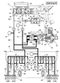
図1および図2に示すように、第1マスタカットバルブ32の上流の液路Paには、その液圧を検出する第1液圧センサSaが接続され、第2マスタカットバルブ33の下流の液路Qbには、その液圧を検出する第2液圧センサSbが接続され、第1マスタカットバルブ32の下流の液路Pbには、その液圧を検出する第3液圧センサScが接続される。尚、第3液圧センサScには、VSA装置23の制御用の液圧センサがそのまま利用される。
As shown in FIG. 1 and FIG. 2, a first fluid pressure sensor Sa that detects the fluid pressure is connected to the fluid path Pa upstream of the first master cut
第1、第2マスタカットバルブ32,33、シミュレータバルブ34、スレーブシリンダ42およびVSA装置23に接続された電子制御ユニットUには、前記第1液圧センサSaと、前記第2液圧センサSbと、前記第3液圧センサScと、ブレーキペダル12のストロークを検出するブレーキペダルストロークセンサSdと、スレーブシリンダ42のストロークを検出するスレーブシリンダストロークセンサSeと、モータ44の回転角を検出するモータ回転角センサSfと、各車輪の車輪速を検出する車輪速センサSg…とが接続される。
The electronic control unit U connected to the first and second master cut
電子制御ユニットUには、モータ44の空転状態、即ち、スレーブシリンダ42からモータ44が脱落したり、アクチュエータ43のギヤ列45やボールねじ機構46が破損したりしてモータ44が無負荷あるいは低負荷で回転する状態を検出すべく、空転検出手段M1が設けられる。
In the electronic control unit U, the
次に、上記構成を備えた本発明の実施の形態の作用について説明する。 Next, the operation of the embodiment of the present invention having the above configuration will be described.
先ず、図3に基づいて正常時における通常の制動作用について説明する。 First, a normal braking action at normal time will be described based on FIG.
システムが正常に機能する正常時に、液路Paに設けた第1液圧センサSaが運転者によるブレーキペダル12の踏み込みを検出すると、常開型電磁弁よりなる第1、第2マスタカットバルブ32,33が励磁されて閉弁し、常閉型電磁弁よりなるシミュレータバルブ34が励磁されて開弁する。これと同時にスレーブシリンダ42のアクチュエータ43が作動して第1、第2ピストン48A,48Bが前進することで第1、第2液圧室50A,50Bにブレーキ液圧が発生し、そのブレーキ液圧は第1、第2出力ポート51A,51Bから液路Pbおよび液路Qbに伝達され、両液路Pb,QbからVSA装置23の開弁したインバルブ56,56;58,58を介してディスクブレーキ装置24,25;28,29のホイールシリンダ26,27;30,31に伝達されて各車輪を制動する。
When the system normally functions, when the first hydraulic pressure sensor Sa provided in the fluid path Pa detects that the driver depresses the
また常閉型電磁弁よりなるシミュレータバルブ34が励磁されて開弁するため、マスタシリンダ11の第2液圧室19が発生したブレーキ液圧が開弁したシミュレータバルブ34を介してストロークシミュレータ35の液圧室39に伝達され、そのピストン38をスプリング37に抗して移動させることで、ブレーキペダル12のストロークを許容するとともに擬似的なペダル反力を発生させて運転者の違和感を解消することができる。
Further, since the
そして液路Qbに設けた第2液圧センサSbで検出したスレーブシリンダ42によるブレーキ液圧が、液路Paに設けた第1液圧センサSaで検出したマスタシリンダ11によるブレーキ液圧に応じた大きさになるように、スレーブシリンダ42のアクチュエータ43の作動を制御することで、運転者がブレーキペダル12に入力する操作量に応じた制動力をディスクブレーキ装置24,25;28,29に発生させることができる。
And the brake hydraulic pressure by the
次に、VSA装置23の作用を説明する。
Next, the operation of the
VSA装置23が作動していない状態では、レギュレータバルブ54,54が消磁されて開弁し、サクションバルブ68,68が消磁されて閉弁し、インバルブ56,56;58,58が消磁されて開弁し、アウトバルブ60,60;61,61が消磁されて閉弁する。従って、運転者が制動を行うべくブレーキペダル12を踏んでスレーブシリンダ42が作動すると、スレーブシリンダ42の第1、第2出力ポート51A,51Bから出力されたブレーキ液圧は、レギュレータバルブ54,54から開弁状態にあるインバルブ56,56;58,58を経てホイールシリンダ26,27;30,31に供給され、四輪を制動することができる。
When the
VSA装置23の作動時には、サクションバルブ68,68が励磁されて開弁した状態でモータ65でポンプ64,64が駆動され、スレーブシリンダ42側からサクションバルブ68,68を経て吸入されてポンプ64,64で加圧されたブレーキ液が、レギュレータバルブ54,54およびインバルブ56,56;58,58に供給される。従って、レギュレータバルブ54,54を励磁して開度を調整することで液路52,52のブレーキ液圧を調圧するとともに、そのブレーキ液圧を開弁したインバルブ56,56;58,58を介してホイールシリンダ26,27;30,31に選択的に供給することで、運転者がブレーキペダル12を踏んでいない状態でも、四輪の制動力を個別に制御することができる。
When the
従って、第1、第2ブレーキアクチュエータ23A,23Bにより四輪の制動力を個別に制御し、旋回内輪の制動力を増加させて旋回性能を高めたり、旋回外輪の制動力を増加させて直進安定性能を高めたりすることができる。
Therefore, the braking force of the four wheels is individually controlled by the first and
また運転者がブレーキペダル12を踏んでの制動中に、例えば左後輪が低摩擦係数路を踏んでロック傾向になったことを車輪速センサSg…の出力に基づいて検出した場合には、第1ブレーキアクチュエータ23Aの一方のインバルブ58を励磁して閉弁するとともに、一方のアウトバルブ61を励磁して開弁することで、左後輪のホイールシリンダ26のブレーキ液圧をリザーバ62に逃がして所定の圧力まで減圧した後、アウトバルブ61を消磁して閉弁することで、左後輪のホイールシリンダ26のブレーキ液圧を保持する。その結果、左後輪のホイールシリンダ26のロック傾向が解消に向かうと、インバルブ58を消磁して開弁することで、スレーブシリンダ42の第1出力ポート51Aからのブレーキ液圧を左後輪のホイールシリンダ26に供給して所定の圧力まで増圧することで、制動力を増加させる。
Further, when the driver depresses the
この増圧によって左後輪が再びロック傾向になった場合には、前記減圧→保持→増圧を繰り返すことにより、左後輪のロックを抑制しながら制動距離を最小限に抑えるABS(アンチロック・ブレーキ・システム)制御を行うことができる。 When the left rear wheel becomes locked again due to this pressure increase, by repeating the pressure reduction → hold → pressure increase, the ABS (anti-lock) that minimizes the braking distance while suppressing the lock on the left rear wheel is repeated.・ Brake system) can be controlled.
以上、左後輪のホイールシリンダ26がロック傾向になったときのABS制御について説明したが、右後輪のホイールシリンダ27、左前輪のホイールシリンダ30、右前輪のホイールシリンダ31がロック傾向になったときのABS制御も同様にして行うことができる。
The ABS control when the left rear
次に、図4に基づいて電源の失陥等によりスレーブシリンダ42が作動不能になった場合の作用について説明する。
Next, an operation when the
電源が失陥すると、常開型電磁弁よりなる第1、第2マスタカットバルブ32,33は自動的に開弁し、常閉型電磁弁よりなるシミュレータバルブ34は自動的に閉弁し、常開型電磁弁よりなるインバルブ56,56;58,58およびレギュレータバルブ54,54は自動的に開弁し、常閉型電磁弁よりなるアウトバルブ60,60;61,61およびサクションバルブ68,68は自動的に閉弁する。この状態では、マスタシリンダ11の第1、第2液圧室17,19に発生したブレーキ液圧は、ストロークシミュレータ35に吸収されることなく第1、第2マスタカットバルブ32,33、レギュレータバルブ54,54およびインバルブ56,56;58,58を通過して各車輪のディスクブレーキ装置24,25;30,31のホイールシリンダ26,27;30,31を作動させ、支障なく制動力を発生させることができる。
When the power supply fails, the first and second master cut
尚、スレーブシリンダ42の失陥時に第1、第2ピストン48A,48Bの後退を規制する部材を別途設けても良い。この場合は通常動作時に駆動抵抗を増加させない構造であることが望ましい。
In addition, you may provide separately the member which controls the reverse of 1st,
次に、図5および図6に基づいてスレーブシリンダ23の制御を説明する。
Next, the control of the
図5に示すように、ブレーキペダルストロークセンサSdで検出したブレーキペダル12のストロークは、ペダルストローク−目標液圧マップにより、スレーブシリンダ42に発生させるべき目標液圧に変換される。このペダルストローク−目標液圧マップは、図6に示す手順で算出される。
As shown in FIG. 5, the stroke of the
即ち、ブレーキペダル12の踏力および車両に発生させるべき減速度の関係を示すマップと、スレーブシリンダ42が発生するブレーキ液圧および車両の減速度の関係を示すマップとから、ブレーキペダル12の踏力およびスレーブシリンダ42に発生させるべきブレーキ液圧の関係を示すマップを算出する。続いて、このマップと、ブレーキペダル12のストロークおよびブレーキペダル12の踏力の関係を示すマップとから、ブレーキペダル12のストロークおよびスレーブシリンダ42に発生させるべき目標液圧の関係を示すマップ(ペダルストローク−目標液圧マップ)を算出する。
That is, from the map indicating the relationship between the depression force of the
図5に戻り、ペダルストローク−目標液圧マップから算出したスレーブシリンダ42に発生させるべき目標液圧と、第2液圧センサSbで検出したスレーブシリンダ42が発生する実液圧との偏差を算出し、この偏差から算出した液圧補正量を目標液圧に加算することで補正を行う。続いて、補正後の目標液圧を、スレーブシリンダ42が発生する液圧とスレーブシリンダ42のストロークとの関係を示すマップに適用し、スレーブシリンダ42の目標ストロークを算出する。続いて、スレーブシリンダ42の目標ストロークに所定のゲインを乗算して算出したモータ44の目標回転角と、モータ回転角センサSfで検出したモータ44の実回転角との偏差を算出し、この偏差から算出したモータ制御量でモータ44を駆動することで、スレーブシリンダ42はブレーキペダルストロークセンサSdで検出したブレーキペダル12のストロークに対応するブレーキ液圧を発生する。
Returning to FIG. 5, the deviation between the target hydraulic pressure to be generated in the
ところで、スレーブシリンダ42からモータ44が脱落したり、アクチュエータ43のギヤ列45やボールねじ機構46が破損したりするとスレーブシリンダ42がブレーキ液圧を発生できなくなるが、モータ44が回転しているために電子制御ユニットUが異常状態を判定せず、マスタシリンダ11が発生するブレーキ液圧によるバックアップが遅れる可能性がある。
By the way, if the
しかしながら本実施の形態によれば、電子制御ユニットUの空転検出手段M1がスレーブシリンダストロークセンサSeで検出したスレーブシリンダ42の実ストロークと、モータ回転角センサSfで検出したモータ44の回転角を時間微分して求めたモータ回転速度とに基づいてモータ44の空転を検出する。
However, according to the present embodiment, the idling detection means M1 of the electronic control unit U detects the actual stroke of the
図7に示すように、空転検出手段M1にはスレーブシリンダストロークと、モータ回転速度との関係を示すマップが予め記憶されている(太い実線参照)。このマップから明らかなように、スレーブシリンダストロークが小さいときには、モータ回転数が高く、スレーブシリンダストロークが増加するのに伴ってモータ回転数が減少するように設定されている。電子制御ユニットUは、モータ回転角センサSfで検出したモータ回転角を時間微分して求めたモータ回転速度が、スレーブシリンダストロークセンサSeで検出したスレーブシリンダストロークの応じた値になるように、モータ44の回転速度を制御する。 As shown in FIG. 7, the idling detection means M1 stores in advance a map showing the relationship between the slave cylinder stroke and the motor rotation speed (see thick solid line). As is apparent from this map, when the slave cylinder stroke is small, the motor rotational speed is high, and the motor rotational speed is set to decrease as the slave cylinder stroke increases. The electronic control unit U allows the motor rotation speed obtained by time differentiation of the motor rotation angle detected by the motor rotation angle sensor Sf to be a value corresponding to the slave cylinder stroke detected by the slave cylinder stroke sensor Se. The rotational speed of 44 is controlled.
このとき、何らかの原因でモータ44が空転すると、モータ44の回転速度が前記マップにより定まる値よりも大きくなる。よって、図7のマップに斜線を施した領域を設定しておき、この領域にスレーブシリンダストロークおよびモータ回転数が入ることで、モータ44の空転を確実かつ速やかに検出することができる。
At this time, if the
そしてモータ44の空転が検出されると、電子制御ユニットUは、第1、第2マスタカットバルブ32,33を開弁し、シミュレータバルブ34を閉弁し、インバルブ56,56;58,58およびレギュレータバルブ54,54を開弁し、アウトバルブ60,60;61,61およびサクションバルブ68,68を閉弁してスレーブシリンダ42の作動を停止し、図4に示すバックアップモードに移行することで、スレーブシリンダ42が発生するブレーキ液圧による制動からマスタシリンダ11が発生するブレーキ液圧による制動に速やかに切り換えることで、運転者の違和感を解消することができる。
When the idling of the
次に、図8に基づいて本発明の第2の実施の形態を説明する。 Next, a second embodiment of the present invention will be described with reference to FIG.
第2の実施の形態は、空転検出手段M1の機能だけが第1の実施の形態と異なっており、その他の構成は同じである。 The second embodiment is different from the first embodiment only in the function of the idling detection means M1, and the other configuration is the same.
図8は、ベクトル制御されるモータ44の指示電圧Vqとトルク電流Iqの関係を示すマップである。モータ44が空転していない正常時には、実線で示すように、指示電圧Vqの増加に伴ってトルク電流Iqは一定の増加率で増加し、指示電圧Vqが更に増加するとトルク電流Iqの増加率は次第に減少する。一方、モータ44が空転する異常時には、破線で示すように、指示電圧Vqの増加に伴ってトルク電流Iqは正常時に比べて大幅に低い一定の増加率で増加する。
FIG. 8 is a map showing the relationship between the command voltage Vq of the
よって、図8のマップに斜線を施した領域を設定し、この領域にモータ44の指示電圧Vqおよびトルク電流Iqが入ることで、モータ44の空転を確実かつ速やかに検出することができる。
Therefore, by setting a hatched area in the map of FIG. 8 and entering the command voltage Vq and torque current Iq of the
但し、スレーブシリンダ42の第1、第2系統の一方がリーク失陥すると、第1、第2液圧室50A,50Bのうちの失陥した側の容積が消滅して正常な側がブレーキ液圧を発生するまでの間はモータ44に殆ど負荷が発生しないため、上記手法ではモータ44の空転とリーク失陥とを判別できなくなる可能性がある。
However, if one of the first and second systems of the
この場合には、スレーブシリンダストロークセンサSeで検出したスレーブシリンダストロークが、正常な側の液圧室50A,50Bにブレーキ液圧が発生する大きさ(例えば、20mm)に達するのを待ち、その後に前記マップによる空転検出を行うことで、スレーブシリンダ42のリーク失陥とモータ44の空転とを確実に判別することができる。
In this case, it waits for the slave cylinder stroke detected by the slave cylinder stroke sensor Se to reach the magnitude (for example, 20 mm) at which the brake hydraulic pressure is generated in the normal
次に、本発明の第3の実施の形態を説明する。 Next, a third embodiment of the present invention will be described.
第3の実施の形態は、駆動モータを走行用駆動源とする電気自動車や、走行用駆動源としてエンジン以外に駆動モータを備えるハイブリッド車両を対象とするものである。 The third embodiment is intended for an electric vehicle using a driving motor as a driving source for driving and a hybrid vehicle including a driving motor other than an engine as a driving source for driving.
第1、第2の実施の形態では、空転検出手段M1がスレーブシリンダ42のモータ44の空転を検出してから、第1、第2マスタカットバルブ32,33を開弁するまでの間、制動力が一時的に落ち込むことで車両の減速度が低下する可能性がある。本実施の形態では、空転検出手段M1がスレーブシリンダ42のモータ44の空転を検出してから、第1、第2マスタカットバルブ32,33を開弁するまでの間、本発明の補助制動手段として機能する駆動モータが発生する回生制動力を一時的に増加させるようになっている。これにより、前記制動力の一時的な落ち込みを駆動モータの回生制動力で補償し、車両の減速度の低下を回避することが可能となる。
In the first and second embodiments, the idling detection means M1 detects the idling of the
以上、本発明の実施の形態を説明したが、本発明はその要旨を逸脱しない範囲で種々の設計変更を行うことが可能である。 The embodiments of the present invention have been described above, but various design changes can be made without departing from the scope of the present invention.
例えば、実施の形態ではモータ回転角センサSfで検出したモータ回転角を時間微分してモータ回転数を検出しているが、モータ回転数センサでモータ回転数を直接検出しても良い。 For example, in the embodiment, the motor rotation angle is detected by time differentiation of the motor rotation angle detected by the motor rotation angle sensor Sf, but the motor rotation speed may be directly detected by the motor rotation speed sensor.
11 マスタシリンダ
12 ブレーキペダル
26 ホイールシリンダ
27 ホイールシリンダ
30 ホイールシリンダ
31 ホイールシリンダ
32 第1マスタカットバルブ(マスタカットバルブ)
33 第2マスタカットバルブ(マスタカットバルブ)
35 ストロークシミュレータ
42 スレーブシリンダ
44 モータ
M1 空転検出手段
U 電子制御ユニット(制御手段)
11
33 Second master cut valve (master cut valve)
35
Claims (4)
前記ブレーキペダル(12)の操作に反力を付与するストロークシミュレータ(35)と、
車輪を制動するホイールシリンダ(26,27,30,31)と、
前記マスタシリンダ(11)および前記ホイールシリンダ(26,27,30,31)を接続する液路を遮断可能なマスタカットバルブ(32,33)と、
前記マスタカットバルブ(32,33)および前記ホイールシリンダ(26,27,30,31)間に配置されて前記ブレーキペダル(12)の操作に応じたブレーキ液圧を発生するスレーブシリンダ(42)と、
前記ブレーキペダル(12)が操作されたときに前記ストロークシミュレータ(35)を作動可能にした状態で前記マスタカットバルブ(32,33)を閉弁して前記スレーブシリンダ(42)を作動させる制御手段(U)と、
前記スレーブシリンダ(42)のモータ(44)の空転を検出する空転検出手段(M1)とを備え、
前記空転検出手段(M1)が前記モータ(44)の空転を検出したときに、前記制御手段(U)は前記マスタカットバルブ(32,33)を開弁して前記マスタシリンダ(11)が発生するブレーキ液圧で前記ホイールシリンダ(26,27,30,31)を作動させることを特徴とする車両用ブレーキ装置。 A master cylinder (11) that generates brake fluid pressure by operating the brake pedal (12);
A stroke simulator (35) for applying a reaction force to the operation of the brake pedal (12);
Wheel cylinders (26, 27, 30, 31) for braking the wheels;
A master cut valve (32, 33) capable of blocking a liquid path connecting the master cylinder (11) and the wheel cylinder (26, 27, 30, 31);
A slave cylinder (42) disposed between the master cut valve (32, 33) and the wheel cylinder (26, 27, 30, 31) for generating a brake fluid pressure in accordance with an operation of the brake pedal (12); ,
Control means for operating the slave cylinder (42) by closing the master cut valve (32, 33) in a state in which the stroke simulator (35) is enabled when the brake pedal (12) is operated. (U) and
Comprising idling detection means (M1) for detecting idling of the motor (44) of the slave cylinder (42),
When the idling detection means (M1) detects idling of the motor (44), the control means (U) opens the master cut valve (32, 33) and the master cylinder (11) is generated. The vehicle brake device is characterized in that the wheel cylinder (26, 27, 30, 31) is operated with a brake fluid pressure.
Priority Applications (5)
| Application Number | Priority Date | Filing Date | Title |
|---|---|---|---|
| JP2011017716A JP5352602B2 (en) | 2011-01-31 | 2011-01-31 | Brake device for vehicle |
| US13/982,305 US9050956B2 (en) | 2011-01-31 | 2012-01-24 | Brake device for vehicle |
| PCT/JP2012/051464 WO2012105379A1 (en) | 2011-01-31 | 2012-01-24 | Brake device for vehicle |
| EP12742537.9A EP2671770B1 (en) | 2011-01-31 | 2012-01-24 | Brake device for vehicle |
| CN201280005500.3A CN103313889B (en) | 2011-01-31 | 2012-01-24 | Braking device for vehicle |
Applications Claiming Priority (1)
| Application Number | Priority Date | Filing Date | Title |
|---|---|---|---|
| JP2011017716A JP5352602B2 (en) | 2011-01-31 | 2011-01-31 | Brake device for vehicle |
Publications (2)
| Publication Number | Publication Date |
|---|---|
| JP2012158214A true JP2012158214A (en) | 2012-08-23 |
| JP5352602B2 JP5352602B2 (en) | 2013-11-27 |
Family
ID=46602598
Family Applications (1)
| Application Number | Title | Priority Date | Filing Date |
|---|---|---|---|
| JP2011017716A Active JP5352602B2 (en) | 2011-01-31 | 2011-01-31 | Brake device for vehicle |
Country Status (5)
| Country | Link |
|---|---|
| US (1) | US9050956B2 (en) |
| EP (1) | EP2671770B1 (en) |
| JP (1) | JP5352602B2 (en) |
| CN (1) | CN103313889B (en) |
| WO (1) | WO2012105379A1 (en) |
Cited By (1)
| Publication number | Priority date | Publication date | Assignee | Title |
|---|---|---|---|---|
| WO2013094592A1 (en) * | 2011-12-22 | 2013-06-27 | 日立オートモティブシステムズ株式会社 | Brake control device |
Families Citing this family (18)
| Publication number | Priority date | Publication date | Assignee | Title |
|---|---|---|---|---|
| KR20130070573A (en) | 2010-03-29 | 2013-06-27 | 콘티넨탈 테베스 아게 운트 코. 오하게 | Brake system for motor vehicles |
| KR20130076809A (en) * | 2010-03-29 | 2013-07-08 | 콘티넨탈 테베스 아게 운트 코. 오하게 | Brake system for motor vehicles |
| DE102012205862A1 (en) * | 2011-04-19 | 2012-10-25 | Continental Teves Ag & Co. Ohg | Brake system for motor vehicles and method for operating a brake system |
| DE102012205860A1 (en) * | 2011-04-19 | 2012-10-25 | Continental Teves Ag & Co. Ohg | Brake system for motor vehicles |
| DE102012205962A1 (en) * | 2011-05-05 | 2012-11-08 | Continental Teves Ag & Co. Ohg | Brake system for motor vehicles and method for operating a brake system |
| JP6088372B2 (en) * | 2013-07-04 | 2017-03-01 | 本田技研工業株式会社 | Brake system for vehicles |
| JP6286192B2 (en) * | 2013-11-26 | 2018-02-28 | 日立オートモティブシステムズ株式会社 | Drive control device for moving body |
| DE102013227066A1 (en) * | 2013-12-23 | 2015-06-25 | Robert Bosch Gmbh | Hydraulic brake system and method for operating a hydraulic brake system |
| DE102014201822A1 (en) * | 2014-02-03 | 2015-08-06 | Robert Bosch Gmbh | Method for operating a vehicle |
| JP6315678B2 (en) * | 2014-03-28 | 2018-04-25 | オートリブ日信ブレーキシステムジャパン株式会社 | Brake fluid pressure generator |
| CN103950443B (en) * | 2014-04-14 | 2016-08-17 | 同济大学 | Pedal sense active control type EHB |
| CN107074216B (en) * | 2014-11-07 | 2019-07-26 | 本田技研工业株式会社 | Vehicle brake system and vehicle brake control method |
| KR101622152B1 (en) * | 2014-12-09 | 2016-06-01 | 주식회사 만도 | Electric brake system |
| DE102014225958A1 (en) * | 2014-12-16 | 2016-06-16 | Continental Teves Ag & Co. Ohg | Brake system for a motor vehicle |
| KR20170031400A (en) * | 2015-09-11 | 2017-03-21 | 주식회사 만도 | Electric brake system |
| CN106218619B (en) * | 2016-08-30 | 2018-11-02 | 邓伟文 | A kind of electro-hydraulic servo braking system with multiple-working mode |
| US10464536B2 (en) * | 2016-11-11 | 2019-11-05 | Honda Motor Co., Ltd. | Adaptive vehicle braking systems, and methods of use and manufacture thereof |
| CN107200001A (en) * | 2017-06-05 | 2017-09-26 | 重庆大学 | HEV/EV regenerative braking control pressurer systems based on front and back wheel bi-motor |
Citations (6)
| Publication number | Priority date | Publication date | Assignee | Title |
|---|---|---|---|---|
| JPH04169368A (en) * | 1990-11-02 | 1992-06-17 | Nissan Motor Co Ltd | Operating pressure control actuator for fluid pressure operating system |
| JPH09109877A (en) * | 1995-10-17 | 1997-04-28 | Aisin Seiki Co Ltd | Method for detecting motor failure of hydraulic pressure control device |
| JP2007060761A (en) * | 2005-08-23 | 2007-03-08 | Nissan Motor Co Ltd | Deceleration controller for hybrid car |
| JP2008174169A (en) * | 2007-01-22 | 2008-07-31 | Honda Motor Co Ltd | Braking device |
| JP2008230362A (en) * | 2007-03-19 | 2008-10-02 | Honda Motor Co Ltd | Braking device |
| JP2009029372A (en) * | 2007-07-30 | 2009-02-12 | Toyota Motor Corp | Pump control device and brake control device |
Family Cites Families (14)
| Publication number | Priority date | Publication date | Assignee | Title |
|---|---|---|---|---|
| US6604795B2 (en) * | 2000-12-28 | 2003-08-12 | Toyota Jidosha Kabushiki Kaisha | Braking system including high-pressure source between master cylinder and brake cylinder |
| DE10123599A1 (en) | 2001-02-12 | 2002-08-22 | Continental Teves Ag & Co Ohg | Electro-hydraulic brake system for motor vehicles |
| DE10252728B4 (en) | 2002-08-13 | 2011-02-17 | Continental Teves Ag & Co. Ohg | Electrohydraulic brake system and method for its monitoring |
| US20070035179A1 (en) | 2003-07-08 | 2007-02-15 | Continental Teves Ag & Co. Ohg | Device and method for identifying hydraulic defects in electrohydraulic brake system |
| JP2005343366A (en) | 2004-06-04 | 2005-12-15 | Honda Motor Co Ltd | Braking device |
| JP4430508B2 (en) * | 2004-10-18 | 2010-03-10 | 本田技研工業株式会社 | Brake device |
| JP4792416B2 (en) * | 2007-03-12 | 2011-10-12 | 本田技研工業株式会社 | Brake device |
| DE102008039960A1 (en) | 2007-09-05 | 2009-03-12 | Continental Teves Ag & Co. Ohg | Brake system for a motor vehicle |
| JP2009090933A (en) | 2007-10-11 | 2009-04-30 | Honda Motor Co Ltd | Braking device |
| US8231181B2 (en) | 2008-01-10 | 2012-07-31 | Honda Motor Co., Ltd. | Brake system |
| JP5212723B2 (en) * | 2009-01-13 | 2013-06-19 | 株式会社アドヴィックス | Brake device |
| DE112010001169B4 (en) * | 2009-03-16 | 2015-02-19 | Honda Motor Co., Ltd. | Method for eliminating blocking of a slave cylinder of a brake device |
| EP2409885B1 (en) | 2009-03-19 | 2013-07-17 | Honda Motor Co., Ltd. | Operating method for a braking device |
| JP5513603B2 (en) * | 2010-02-26 | 2014-06-04 | 本田技研工業株式会社 | Brake device for vehicle and control method for vehicle brake device |
-
2011
- 2011-01-31 JP JP2011017716A patent/JP5352602B2/en active Active
-
2012
- 2012-01-24 WO PCT/JP2012/051464 patent/WO2012105379A1/en active Application Filing
- 2012-01-24 US US13/982,305 patent/US9050956B2/en active Active
- 2012-01-24 EP EP12742537.9A patent/EP2671770B1/en active Active
- 2012-01-24 CN CN201280005500.3A patent/CN103313889B/en active Active
Patent Citations (6)
| Publication number | Priority date | Publication date | Assignee | Title |
|---|---|---|---|---|
| JPH04169368A (en) * | 1990-11-02 | 1992-06-17 | Nissan Motor Co Ltd | Operating pressure control actuator for fluid pressure operating system |
| JPH09109877A (en) * | 1995-10-17 | 1997-04-28 | Aisin Seiki Co Ltd | Method for detecting motor failure of hydraulic pressure control device |
| JP2007060761A (en) * | 2005-08-23 | 2007-03-08 | Nissan Motor Co Ltd | Deceleration controller for hybrid car |
| JP2008174169A (en) * | 2007-01-22 | 2008-07-31 | Honda Motor Co Ltd | Braking device |
| JP2008230362A (en) * | 2007-03-19 | 2008-10-02 | Honda Motor Co Ltd | Braking device |
| JP2009029372A (en) * | 2007-07-30 | 2009-02-12 | Toyota Motor Corp | Pump control device and brake control device |
Cited By (1)
| Publication number | Priority date | Publication date | Assignee | Title |
|---|---|---|---|---|
| WO2013094592A1 (en) * | 2011-12-22 | 2013-06-27 | 日立オートモティブシステムズ株式会社 | Brake control device |
Also Published As
| Publication number | Publication date |
|---|---|
| EP2671770A4 (en) | 2014-07-30 |
| US20140008966A1 (en) | 2014-01-09 |
| JP5352602B2 (en) | 2013-11-27 |
| CN103313889B (en) | 2015-11-25 |
| CN103313889A (en) | 2013-09-18 |
| EP2671770B1 (en) | 2015-12-09 |
| EP2671770A1 (en) | 2013-12-11 |
| US9050956B2 (en) | 2015-06-09 |
| WO2012105379A1 (en) | 2012-08-09 |
Similar Documents
| Publication | Publication Date | Title |
|---|---|---|
| JP5352602B2 (en) | Brake device for vehicle | |
| JP5204250B2 (en) | Brake device for vehicle | |
| US8926027B2 (en) | Vehicle braking system | |
| JP5734319B2 (en) | Brake device for vehicle | |
| JP5123972B2 (en) | Brake device for vehicle and control method for vehicle brake device | |
| JP4832460B2 (en) | Brake device | |
| JP5484359B2 (en) | Control method for vehicle brake device | |
| JP5352669B2 (en) | Brake device for vehicle | |
| US20100001577A1 (en) | Brake system | |
| JP6678996B2 (en) | Hydraulic control device and brake system | |
| WO2011105405A1 (en) | Vehicle brake device and vehicle brake device control method | |
| JP4801823B2 (en) | Initial position setting method for electric cylinder for generating hydraulic pressure | |
| JP2007230435A (en) | Brake device | |
| JP6544335B2 (en) | Vehicle braking system | |
| JP5107857B2 (en) | Brake device for vehicle | |
| JP4950149B2 (en) | Brake device | |
| JP2010089599A (en) | Vehicular brake device | |
| JP2012176745A (en) | Brake device for vehicle | |
| JP5461496B2 (en) | Brake device for vehicle | |
| JP5030802B2 (en) | Brake device | |
| JP6029281B2 (en) | Brake device for vehicle | |
| JP2010047044A (en) | Vehicular brake device | |
| WO2021060162A1 (en) | Vehicle braking device |
Legal Events
| Date | Code | Title | Description |
|---|---|---|---|
| A131 | Notification of reasons for refusal |
Free format text: JAPANESE INTERMEDIATE CODE: A131 Effective date: 20130403 |
|
| A521 | Request for written amendment filed |
Free format text: JAPANESE INTERMEDIATE CODE: A523 Effective date: 20130531 |
|
| TRDD | Decision of grant or rejection written | ||
| A01 | Written decision to grant a patent or to grant a registration (utility model) |
Free format text: JAPANESE INTERMEDIATE CODE: A01 Effective date: 20130807 |
|
| A61 | First payment of annual fees (during grant procedure) |
Free format text: JAPANESE INTERMEDIATE CODE: A61 Effective date: 20130826 |
|
| R150 | Certificate of patent or registration of utility model |
Ref document number: 5352602 Country of ref document: JP Free format text: JAPANESE INTERMEDIATE CODE: R150 Free format text: JAPANESE INTERMEDIATE CODE: R150 |
|
| R250 | Receipt of annual fees |
Free format text: JAPANESE INTERMEDIATE CODE: R250 |