JP2012157799A - Backwashing strainer - Google Patents
Backwashing strainer Download PDFInfo
- Publication number
- JP2012157799A JP2012157799A JP2011017908A JP2011017908A JP2012157799A JP 2012157799 A JP2012157799 A JP 2012157799A JP 2011017908 A JP2011017908 A JP 2011017908A JP 2011017908 A JP2011017908 A JP 2011017908A JP 2012157799 A JP2012157799 A JP 2012157799A
- Authority
- JP
- Japan
- Prior art keywords
- filter element
- fluid
- strainer
- foreign matter
- backwashing
- Prior art date
- Legal status (The legal status is an assumption and is not a legal conclusion. Google has not performed a legal analysis and makes no representation as to the accuracy of the status listed.)
- Pending
Links
Images

Abstract
Description
この発明は、流体が流れる配管に取付け、流体に含まれている異物をフィルターエレメントで除去して流体を清浄化する逆流洗浄ストレーナー、更に詳しくは、フィルターエレメントの目詰まりによって濾過機能が低下すると、流体の圧力を利用して付着した異物を洗浄除去し、前記濾過機能を復元させることができるようにした逆流洗浄ストレーナーに関する。 This invention is attached to a pipe through which a fluid flows, and a backwashing strainer that cleans the fluid by removing foreign substances contained in the fluid with a filter element, more specifically, when the filtration function is reduced due to clogging of the filter element, The present invention relates to a back-flow cleaning strainer that uses a fluid pressure to clean and remove adhering foreign matter so that the filtration function can be restored.
従来、工場やプラント等において使用される水のような流体が流れる配管に取付けられ、流体に含まれている異物を除去して清浄化するためのストレーナーの基本的な構造は、流体が流れるストレーナー本体の内部にフィルターエレメントを組み込み、流体がこのフィルターエレメントを上流から下流に流れて通過することで異物を捕捉するようになっている。 Conventionally, the basic structure of a strainer that is attached to a pipe through which a fluid such as water used in factories or plants flows and that removes foreign substances contained in the fluid is a strainer through which the fluid flows. A filter element is incorporated inside the main body, and a fluid flows through the filter element from upstream to downstream to capture foreign matter.
上記のようなストレーナーにおいては、濾過時間の経過と共にフィルターエレメントが閉塞して濾過機能が低下するため、定期的な濾過機能の回復処置が必要になり、この回復処置として、ストレーナーを分解してフィルターエレメントを取出し、フィルターエレメントを人力等で洗浄した後、再び組立てる方法は、洗浄と分解組立てに手間がかかるという問題がある。 In the strainer as described above, the filter element is clogged with the passage of filtration time and the filtration function is lowered. Therefore, it is necessary to periodically restore the filtration function. The method of taking out the element, cleaning the filter element manually, and then reassembling has the problem that it takes time and effort to clean and disassemble.
このため、フィルターエレメントに対する流体の流れを切り換え、濾過時と逆方向に流した洗浄流体の圧力で、フィルターエレメントに付着している異物を剥離させ、異物の混入した洗浄流体を流体経路と別の部分に取出し、ストレーナーを分解することなくフィルターエレメントの濾過機能を回復させることができるようにした逆流洗浄ストレーナーが提案されている。 For this reason, the flow of the fluid to the filter element is switched, the foreign matter adhering to the filter element is peeled off by the pressure of the cleaning fluid that flows in the opposite direction to that during filtration, and the cleaning fluid mixed with foreign matter is separated from the fluid path. A backwashing strainer has been proposed which can be taken out of the part and restored the filtering function of the filter element without disassembling the strainer.
上記した従来の逆流洗浄ストレーナーは、ストレーナー本体の内部にフィルターエレメントを組み込み、ストレーナー本体の内部を一次側と二次側に分け、前記ストレーナー本体に、一次側と導通する原流体供給部と、二次側と導通し、濾過流体の取出し及び二次側に洗浄流体を切り換え供給するための洗浄流体供給部を設け、更に、洗浄流体の排出部を前記一次側に接続した構造になっている(例えば、特許文献1参照)。 The conventional backwashing strainer described above incorporates a filter element inside the strainer main body, divides the inside of the strainer main body into a primary side and a secondary side, and supplies the raw fluid supply section that is electrically connected to the primary side to the strainer body. It is connected to the secondary side, provided with a cleaning fluid supply unit for taking out the filtered fluid and switching and supplying the cleaning fluid to the secondary side, and further has a structure in which a cleaning fluid discharge unit is connected to the primary side ( For example, see Patent Document 1).
通常の濾過時は、原流体供給部から一次側に流入した流体は、フィルターエレメントを通過して二次側に流れ、異物が除去された濾過後の流体は洗浄流体供給部に流出する。 During normal filtration, the fluid that has flowed into the primary side from the raw fluid supply unit flows through the filter element to the secondary side, and the filtered fluid from which foreign matter has been removed flows out to the cleaning fluid supply unit.
フィルターエレメントを逆洗するには、原流体供給部を閉口させて排出部を開口させ、洗浄流体供給部から洗浄流体を二次側に供給し、洗浄流体がフィルターエレメントを濾過時と逆に通過することで、フィルターエレメントに付着している異物を剥離除去し、汚れた洗浄流体を異物と共に排出部に取出すことにより、フィルターエレメントの濾過機能を回復させるものである。 To backwash the filter element, close the raw fluid supply part, open the discharge part, supply cleaning fluid from the cleaning fluid supply part to the secondary side, and the cleaning fluid passes through the filter element in the reverse direction of filtration. By doing so, the foreign matter adhering to the filter element is peeled and removed, and the dirty cleaning fluid is taken out together with the foreign matter to the discharge portion, thereby restoring the filter function of the filter element.
ところで、上記した従来の逆流洗浄ストレーナーは、フィルターエレメントを定位置に固定配置したまま逆洗するので、フィルターエレメントに対して洗浄用の流体を、濾過時の原流体の流れの下流側から供給しなければならず、原流体そのものの流れを逆洗に使用することができないという不便がある。 By the way, the above-described conventional backwashing strainer performs backwashing while the filter element is fixedly arranged at a fixed position, so that the cleaning fluid is supplied to the filter element from the downstream side of the flow of the raw fluid during filtration. There is an inconvenience that the flow of the raw fluid itself cannot be used for backwashing.
また、下流側から洗浄用の流体を供給する構造では、逆洗後において下流側の管路内に洗浄用の流体が残り、濾過を再開すると濾過された原流体に洗浄用の流体が混入することになり、このため、濾過後の原流体を使用する部分に洗浄用の流体が流入するという不都合がある。 Further, in the structure in which the cleaning fluid is supplied from the downstream side, the cleaning fluid remains in the downstream pipe line after backwashing, and when the filtration is restarted, the cleaning fluid is mixed into the filtered raw fluid. For this reason, there is an inconvenience that the cleaning fluid flows into the portion where the filtered raw fluid is used.
そこで、この発明の課題は、フィルターエレメントの逆洗が濾過時の原流体の流れの上流側から行えるようにし、原流体そのものの流れを逆洗に使用することができると共に、洗浄用の流体を用いた場合も、濾過された原流体に洗浄用の流体が混入することなくフィルターエレメントの逆洗が行える逆流洗浄ストレーナーを提供することにある。 Therefore, an object of the present invention is to allow the back washing of the filter element from the upstream side of the flow of the raw fluid at the time of filtration, so that the flow of the raw fluid itself can be used for back washing, and the washing fluid can be used. Even when used, it is an object of the present invention to provide a backwashing strainer capable of backwashing the filter element without mixing a washing fluid into the filtered raw fluid.
上記のような課題を解決するため、この発明は、流体が流れるストレーナー本体の内部にフィルターエレメントを、流体の濾過位置と、フィルターエレメントを通過する流体の流れが、濾過時とは逆に流れる洗浄位置との間を移動可能となるよう組み込み、前記フィルターエレメントに駆動軸を接続し、この駆動軸でフィルターエレメントを洗浄位置に移動させ、流体の逆流によってフィルターエレメントの表面に付着した異物を洗浄除去するようにしたものである。 In order to solve the above-described problems, the present invention provides a filter element inside a strainer main body through which a fluid flows, and a cleaning position in which the fluid is filtered and the flow of the fluid passing through the filter element flows in the opposite direction to that during filtration. Installed so that it can move between positions, connect a drive shaft to the filter element, move the filter element to the cleaning position with this drive shaft, and clean and remove foreign matter adhering to the surface of the filter element due to the backflow of fluid It is what you do.
上記フィルターエレメントの底部に異物排出口を設け、フィルターエレメントが濾過位置にあるとき異物排出口が閉口し、フィルターエレメントが洗浄位置にあるとき異物排出口が開口するようにしてもよい。 A foreign matter discharge port may be provided at the bottom of the filter element so that the foreign matter discharge port is closed when the filter element is at the filtering position, and the foreign matter discharge port is opened when the filter element is at the cleaning position.
また、上記ストレーナー本体の流体入口と流体出口に差圧スイッチを接続し、前記ストレーナー本体の流体入口に流体導入路と洗浄水導入路を切り換え可能に接続し、フィルターエレメントの表面に異物が付着して設定値以上の圧力差が生じたときに、前記差圧スイッチによって、前記ストレーナー本体の流体入口の導通を流体導入路から洗浄水導入路に切り換え、同時に上記駆動軸と連動させた駆動装置を起動させ、フィルターエレメントを濾過位置から洗浄位置に移動させるようにすることができる。 Further, a differential pressure switch is connected to the fluid inlet and the fluid outlet of the strainer body, and a fluid introduction path and a washing water introduction path are switchably connected to the fluid inlet of the strainer body so that foreign matter adheres to the surface of the filter element. When the pressure difference more than the set value occurs, the differential pressure switch switches the continuity of the fluid inlet of the strainer body from the fluid introduction path to the washing water introduction path, and at the same time, a drive device linked with the drive shaft It can be activated to move the filter element from the filtration position to the washing position.
上記フィルターエレメントの表面路材としてのスクリーンが、金属製素材、合成樹脂製素材又は布製素材の何れかによって形成されている構造とすることができる。 The screen as the surface path material of the filter element can be made of a metal material, a synthetic resin material, or a cloth material.
更に、上記逆流洗浄ストレーナーを用い、この逆流洗浄ストレーナーを流体導入路に対して複数並列設置し、濾過運転継続中に交互にフィルターエレメントの逆流洗浄を行うようにすることができる。 Furthermore, a plurality of backwashing strainers can be installed in parallel with the fluid introduction path by using the backwashing strainer, and the backwashing of the filter elements can be performed alternately during the filtration operation.
ここで、上記ストレーナー本体は有底の筒状に形成され、その内部が中間部内周に設けた円形鍔状の支持壁を境に上部流入室と下部流出室に区切られ、上部流入室に流体入口が連通状に設けられ、下部流出室に流体出口が連通状に設けられている。 Here, the strainer body is formed in a cylindrical shape with a bottom, and the inside thereof is divided into an upper inflow chamber and a lower outflow chamber with a circular bowl-shaped support wall provided in the inner periphery of the intermediate portion as a boundary, and fluid is transferred to the upper inflow chamber. The inlet is provided in communication, and the fluid outlet is provided in communication in the lower outflow chamber.
上記ストレーナー本体内に収納したフィルターエレメントは、上記支持壁の内径に収まる外径で上端が開口した円筒状に形成され、上端外周に設けたフランジが支持壁上に重なる状態で下部流出室内に収まり、この状態から上方への移動が可能となり、上端の開口が上部流入室に連通している。 The filter element housed in the strainer body is formed in a cylindrical shape having an outer diameter that fits within the inner diameter of the support wall and an upper end that is open, and a flange provided on the outer periphery of the upper end fits in the lower outflow chamber in a state of overlapping the support wall. In this state, it is possible to move upward, and the opening at the upper end communicates with the upper inflow chamber.
上記ストレーナー本体の上部に設けた駆動装置はシリンダを用い、フィルターエレメントの上端部に取付けた駆動軸とシリンダのピストン杆を連結し、前記シリンダによってフィルターエレメントを、下部流出室内に収まる濾過位置と、上部流入室に引上げた逆洗位置との間を上下に移動させることができるようになっている。 The drive device provided on the upper part of the strainer body uses a cylinder, connects a drive shaft attached to the upper end of the filter element and a piston rod of the cylinder, and a filtration position where the filter element is accommodated in the lower outflow chamber by the cylinder, It can be moved up and down between the backwash position pulled up to the upper inflow chamber.
上記ストレーナー本体の流体入口から上部流入室に入った原流体はフィルターエレメント内に流入し、このフィルターエレメントの周壁に形成されているスクリーンを内側から外側に向けて通過し、濾過された状態で下部流出室から流体出口へ流出する。 The raw fluid that has entered the upper inflow chamber from the fluid inlet of the strainer body flows into the filter element, passes through the screen formed on the peripheral wall of the filter element from the inside to the outside, and is filtered in the lower part. Outflow from the outflow chamber to the fluid outlet.
上記フィルターエレメントの下部には、筒状の異物排出口が連通状に設けられ、この異物排出口はストレーナー本体の底部に設けた異物排出管内に上下動可能に収まり、フィルターエレメントが下部流出室内に収まる下降位置にあるとき、異物排出口の下端が閉鎖され、濾過時に原流体が異物排出口から流出しないようになっている。 A cylindrical foreign matter discharge port is provided in communication with the lower portion of the filter element, and the foreign matter discharge port is movably accommodated in a foreign matter discharge pipe provided at the bottom of the strainer body so that the filter element is placed in the lower outflow chamber. When in the lowered position, the lower end of the foreign matter discharge port is closed, so that the raw fluid does not flow out of the foreign matter discharge port during filtration.
また、逆洗時にフィルターエレメントを上部流入室に引上げると、流体入口から上部流入室に入った流体は、フィルターエレメントの周壁に形成されているスクリーンを外側から内側に向けて通過し、流体の逆流によってフィルターエレメントの表面に付着した異物を洗浄除去し、フィルターエレメント内の汚れた流体は、開口した異物排出口から異物排出管を通って排出される。 Also, when the filter element is pulled up to the upper inflow chamber during backwashing, the fluid that has entered the upper inflow chamber from the fluid inlet passes through the screen formed on the peripheral wall of the filter element from the outside to the inside, The foreign matter adhering to the surface of the filter element is washed away by the reverse flow, and the dirty fluid in the filter element is discharged from the opened foreign matter discharge port through the foreign matter discharge pipe.
この発明によると、ストレーナー本体の内部にフィルターエレメントを移動可能となるよう組み込み、このフィルターエレメントを駆動軸で洗浄位置に移動させ、流体の逆流によってフィルターエレメントの表面に付着した異物を洗浄除去するようにしたので、フィルターエレメントの逆洗が濾過時の原流体の流れの上流側から行え、原流体そのものの流れを逆洗に使用することができることになる。 According to the present invention, the filter element is incorporated in the strainer body so as to be movable, the filter element is moved to the cleaning position by the drive shaft, and the foreign matter adhering to the surface of the filter element by the back flow of the fluid is cleaned and removed. Therefore, the filter element can be backwashed from the upstream side of the flow of the raw fluid during filtration, and the flow of the raw fluid itself can be used for backwashing.
また、濾過時の原流体の流れの上流側から逆洗が行え、異物を含む流体を異物排出口から外部に排出することにより、逆洗に洗浄用の流体を用いた場合でも、濾過された原流体に洗浄用の流体を混入させることなくフィルターエレメントの逆洗が行える。 In addition, backwashing can be performed from the upstream side of the flow of the original fluid during filtration, and even if a cleaning fluid is used for backwashing, the fluid containing foreign matter is discharged to the outside through the foreign matter discharge port. The filter element can be backwashed without mixing the cleaning fluid with the raw fluid.
更に、ストレーナー本体の流体入口と流体出口に差圧スイッチを接続し、流体入口と流体出口に設定値以上の圧力差が生じたときに、駆動軸と連動させた駆動装置を起動させ、フィルターエレメントを濾過位置から洗浄位置に移動させるようにすると、フィルターエレメントの逆洗による機能回復が自動的に行えるようになる。 Further, a differential pressure switch is connected to the fluid inlet and the fluid outlet of the strainer body, and when a pressure difference greater than a set value is generated between the fluid inlet and the fluid outlet, the drive device linked with the drive shaft is activated, and the filter element When the filter is moved from the filtration position to the washing position, the function can be automatically restored by backwashing the filter element.
以下、この発明の実施の形態を図示例と共に説明する。 Hereinafter, embodiments of the present invention will be described with reference to the drawings.
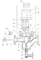
図1と図2のように、この発明の逆流洗浄ストレーナー1は、ストレーナー本体2の内部にフィルターエレメント3を上下動可能に組み込み、前記ストレーナー本体2の上部にフィルターエレメント3を上下動させる駆動装置4を取付け、前記ストレーナー本体2の外部で上下軸線を挟む一方に濾過せんとする原流体(液体)の流体入口5と他方に流体出口6を設けた構造になっている。
As shown in FIGS. 1 and 2, the backwashing strainer 1 of the present invention incorporates a
上記ストレーナー本体2は、有底の円形筒状に形成され、その内部が上下中間部内周に設けた円形鍔状の支持壁7を境にして上部流入室8と下部流出室9に区切られ、上部流入室8の上端は、ストレーナー本体2にボルト、ナットを用いて結合した蓋部材10によって水密に閉鎖され、ストレーナー本体2の側面に外方へ突設した流体入口5が上部流入室8と側面下部の位置で連通し、同じくストレーナー本体2の側面に外方へ突設した流体出口6が下部流出室9の側面部で連通している。
The
上記フィルターエレメント3は、上記支持壁7の内径に丁度嵌まり合って収まる外径の円筒状となり、その上端が開口して底部が窄まり状となる形状に形成され、上端外周に周設したフランジ11が上部流入室8の内径に対して僅かな隙間を設けて嵌り合う外径に設定されている。
The
上記フランジ11が支持壁7上に重なる状態で、フィルターエレメント3は全体が下部流出室9内に収まり、この状態から上方への移動が可能となっていると共に、上端の開口が上部流入室8に臨んでその内部が上部流入室8と連通している。
With the
このフィルターエレメント3の円筒状となる周壁が内外に通過する流体を濾過するためのスクリーン12となり、前記スクリーン12の表面路材が、金属製素材、合成樹脂製素材又は布製素材の何れかによって形成されている。
The cylindrical peripheral wall of the
前記フィルターエレメント3の上端部に、上端開口から内部への流体の流入を確保した状態で駆動軸13の下端が同軸心の配置で連結され、この駆動軸13は上記蓋部材10を上下に移動可能となるように貫通し、この貫通部分をパッキンとパッキン押え及びグランドボルトにより水密状態に保持し、ストレーナー本体2の外部から該駆動軸13でフィルターエレメント3を上下動させることができるようになっている。
The lower end of the
上記ストレーナー本体2の上部に固定した蓋部材10の上に支柱14を介して駆動装置4が取付けられ、この駆動装置4は図示の場合シリンダを用い、そのピストン杆4aを上記駆動軸13と軸継手15を用いて結合し、前記シリンダによってフィルターエレメント3を、図1に示した下部流出室9内に収まる濾過位置と、図2に示した上部流入室8に引上げた洗浄位置との間を上下に移動させるようになっている。
A
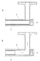
上記フィルターエレメント3の小径に絞られた底部には、筒状の異物排出口16が連通状となるよう同軸心状に設けられ、この異物排出口16はストレーナー本体2の底部に設けた異物排出管17内に上下動可能に収まり、異物排出管17は下部が直角に屈曲し、垂直部分の下端部には、異物排出口16の下端を閉口させるための弁座18が設けてある。
A cylindrical foreign
図1のように、フィルターエレメント3が下部流出室9内に収まる濾過位置にあるとき、図3(a)のように、異物排出口16の下端開口が弁座18に当接して閉口状態となり、フィルターエレメント3内の流体が異物排出管17に流出しないようになっている。
As shown in FIG. 1, when the
また、図2のように、フィルターエレメント3を上部流入室8に引上げた洗浄位置にすると、図3(b)のように、異物排出口16も一体に上昇して下端が弁座18から離れ、異物排出口16の下端開口が開放状態となり、フィルターエレメント3内の流体が異物排出口16の下端開口から異物排出管17に流出することになる。
2, when the
上記ストレーナー本体2の流体入口5と流体出口6に差圧スイッチ19を接続し、前記ストレーナー本体2の流体入口5に流体導入路20と洗浄水導入路21をそれぞれバルブ22、23の操作によって切り換え可能に接続し、前記差圧スイッチ19による流体入口5と流体出口6の圧力差の変動検知により、駆動装置4及びバルブ22、23を作動させ、フィルターエレメント3の濾過と逆洗の切り換えの位置を自動的に行うようにしている。
A
この発明のストレーナー1は、上記のような構成であり、ストレーナー本体2における流体入口5の流体導入路20と流体出口6を原流体が流れる配管の途中に接続し、原流体に含まれている異物をフィルターエレメント3で濾過して捕捉せんとするものであり、通常の濾過時は、図1のように、フィルターエレメント3は下部流出室9内に下降した濾過位置にあり、フランジ11が支持壁7上に重なる状態で上端開口が上部流入室8の底部と連通し、下降した異物排出口16の下端開口は弁座18に当接して閉口している。
The strainer 1 of the present invention is configured as described above, and is connected to the
流体導入路20のバルブ22が開となると、濾過せんとする原流体は流体導入路20から流体入口5、上部流入室8を通ってフィルターエレメント3の内側に流入し、このフィルターエレメント3のスクリーン12を内側から外側に向けて通過し、原流体に含まれている異物がスクリーン12で捕捉され、清浄になった流体は下部流出室9から流体出口6に流出する。
When the
上記のような濾過時において、フィルターエレメント3のスクリーン12に対して異物の付着量が少ない場合、流体入口5と流体出口6の原流体の圧力に大きな差圧が生じないため、差圧は設定値の範囲となるので差圧スイッチ19は図1のようにオフとなり、駆動装置4はフィルターエレメント3の下降位置にある状態を保っている。
During filtration as described above, if the amount of foreign matter attached to the
上記のようにして原流体の濾過が行われ、フィルターエレメント3におけるスクリーン12の内面に異物が付着してくると、スクリーン12を通過する原流体の流れが悪くなって濾過機能が低下し、このため、ストレーナー本体2の流体出口6での流体の圧力が低下することで、流体入口5と流体出口6において原流体の圧力差が発生し、この圧力差が設定値以上になると、図2のように、この圧力差の検出によってオンとなった差圧スイッチ19は駆動軸13と連動させた駆動装置4を起動させ、フィルターエレメント3を濾過位置から上部流入室8に位置する洗浄位置に引上げる。
When the raw fluid is filtered as described above and foreign matter adheres to the inner surface of the
図2で示したように、上部流入室8内の洗浄位置にあるフィルターエレメント3は、その上端部が流体入口5よりも高い位置になり、上部流入室8の内周とフランジ11の外周の隙間は狭く、フィルターエレメント3の筒状となる下端部は支持壁7の内径に嵌まり合った状態のままであり、スクリーン12が流体入口5と同じ高さレベルとなる。
As shown in FIG. 2, the
上記差圧スイッチ19は、圧力差の検出によるオンによって、流体導入路20のバルブ22を閉じると同時に洗浄流体導入路21のバルブ23を開き、また、フィルターエレメント3を洗浄位置に引上げると、図3(b)のように、一体に上昇した異物排出口16は下端開口が弁座18から離反して開放される。
When the
このため、洗浄位置に移動させたフィルターエレメント3に対する洗浄流体の流れは、スクリーン12に対して外側から内側へ向けて濾過時とは逆の流れとなり、この洗浄流体の逆流により、スクリーン12の内面に付着している異物が剥離除去される。
For this reason, the flow of the cleaning fluid with respect to the
フィルターエレメント3の内側に発生した洗浄後の汚れた流体は、フィルターエレメント3の下部に連ねた異物排出口16から異物排出管17に流出することになり、流体出口6に流れ出ることはない。
The cleaned dirty fluid generated inside the
このようにして洗浄流体を所定時間流し、フィルターエレメント3のスクリーン12を逆流洗浄して濾過機能が回復すると、差圧スイッチ19を強制的にオフに戻すようにする。
In this way, the cleaning fluid is allowed to flow for a predetermined time, and when the
これにより、先ず、流体導入路20のバルブ22を開いて同時に洗浄流体導入路21のバルブ23を閉じ、原流体でフィルターエレメント3の内側に発生した洗浄後の汚れた流体を異物排出管17に流出させ、原流体の経路に汚れた流体が流入することのないようにした後、次に、駆動装置4が作動してフィルターエレメント3を下部流出室9内に収まる濾過位置に下降させ、異物排出口16の下端開口を図3(a)のように閉口状態にすれば、原流体はフィルターエレメント3のスクリーン12を内側から外側に流れ、図1のように、下部流出室9から流体出口6に流出する通常の濾過状態に戻る。
As a result, first, the
なお、図示例では、逆流洗浄ストレーナー1を単独使用したが、逆流洗浄ストレーナー1を流体導入路に対して複数並列設置するようにしてもよく、複数並列設置させることにより、濾過運転継続中に交互にフィルターエレメント3の逆流洗浄を行うようにすることができ、濾過せんとする流体の流れを停止させることがないという利点がある。
In the illustrated example, the backwashing strainer 1 is used alone. However, a plurality of backwashing strainers 1 may be installed in parallel to the fluid introduction path. Therefore, the
1 逆流洗浄ストレーナー
2 ストレーナー本体
3 フィルターエレメント
4 駆動装置
5 流体入口
6 流体出口
7 支持壁
8 上部流入室
9 下部流出室
10 蓋部材
11 フランジ
12 スクリーン
13 駆動軸
14 支柱
15 軸継手
16 異物排出口
17 異物排出管
18 弁座
19 差圧スイッチ
20 流体導入路
21 洗浄水導入路
22 バルブ
23 バルブ
DESCRIPTION OF SYMBOLS 1 Backflow washing | cleaning
Claims (5)
前記フィルターエレメントに駆動軸を接続し、この駆動軸でフィルターエレメントを洗浄位置に移動させ、流体の逆流によってフィルターエレメントの表面に付着した異物を洗浄除去するようになっている逆流洗浄ストレーナー。 The filter element is incorporated inside the strainer body through which the fluid flows so that the fluid can be moved between a filtration position of the fluid and a cleaning position where the flow of the fluid passing through the filter element flows in the opposite direction to the filtration time.
A backwashing strainer in which a drive shaft is connected to the filter element, the filter element is moved to a cleaning position by the drive shaft, and foreign matter adhering to the surface of the filter element is washed away by the backflow of fluid.
Priority Applications (1)
| Application Number | Priority Date | Filing Date | Title |
|---|---|---|---|
| JP2011017908A JP2012157799A (en) | 2011-01-31 | 2011-01-31 | Backwashing strainer |
Applications Claiming Priority (1)
| Application Number | Priority Date | Filing Date | Title |
|---|---|---|---|
| JP2011017908A JP2012157799A (en) | 2011-01-31 | 2011-01-31 | Backwashing strainer |
Publications (1)
| Publication Number | Publication Date |
|---|---|
| JP2012157799A true JP2012157799A (en) | 2012-08-23 |
Family
ID=46838799
Family Applications (1)
| Application Number | Title | Priority Date | Filing Date |
|---|---|---|---|
| JP2011017908A Pending JP2012157799A (en) | 2011-01-31 | 2011-01-31 | Backwashing strainer |
Country Status (1)
| Country | Link |
|---|---|
| JP (1) | JP2012157799A (en) |
Cited By (7)
| Publication number | Priority date | Publication date | Assignee | Title |
|---|---|---|---|---|
| CN102872619A (en) * | 2012-10-26 | 2013-01-16 | 江苏通用环保集团有限公司 | Impeller washing device for fiber filter media filter |
| CN103861340A (en) * | 2012-12-11 | 2014-06-18 | 虞文娟 | Vertical high cleaning filter |
| EP2756874A1 (en) * | 2013-01-18 | 2014-07-23 | Krones AG | Filter device |
| CN105833588A (en) * | 2016-05-30 | 2016-08-10 | 海宁市倍世环保科技有限公司 | Backwashing device of filter |
| CN114470999A (en) * | 2021-12-29 | 2022-05-13 | 国家能源集团煤焦化有限责任公司 | Gas filter |
| CN114849348A (en) * | 2022-05-13 | 2022-08-05 | 杭州青云新材料股份有限公司 | Stock solution filter element cleaning system and cleaning process |
| CN115608039B (en) * | 2022-12-14 | 2023-02-28 | 黎耀智能科技有限公司 | Filter for water pump split type multi-connected system and water pump split type multi-connected system |
Citations (5)
| Publication number | Priority date | Publication date | Assignee | Title |
|---|---|---|---|---|
| JPS6171209U (en) * | 1984-10-17 | 1986-05-15 | ||
| JPS61187909A (en) * | 1985-02-15 | 1986-08-21 | Hitachi Ltd | Foreign matter removing device |
| JPH0347008U (en) * | 1989-09-07 | 1991-04-30 | ||
| JP2000117017A (en) * | 1998-08-13 | 2000-04-25 | Kazunao Kameyama | Y-shaped strainer |
| JP4376068B2 (en) * | 2004-01-07 | 2009-12-02 | 中国電力株式会社 | Strainer backwash system |
-
2011
- 2011-01-31 JP JP2011017908A patent/JP2012157799A/en active Pending
Patent Citations (5)
| Publication number | Priority date | Publication date | Assignee | Title |
|---|---|---|---|---|
| JPS6171209U (en) * | 1984-10-17 | 1986-05-15 | ||
| JPS61187909A (en) * | 1985-02-15 | 1986-08-21 | Hitachi Ltd | Foreign matter removing device |
| JPH0347008U (en) * | 1989-09-07 | 1991-04-30 | ||
| JP2000117017A (en) * | 1998-08-13 | 2000-04-25 | Kazunao Kameyama | Y-shaped strainer |
| JP4376068B2 (en) * | 2004-01-07 | 2009-12-02 | 中国電力株式会社 | Strainer backwash system |
Cited By (9)
| Publication number | Priority date | Publication date | Assignee | Title |
|---|---|---|---|---|
| CN102872619A (en) * | 2012-10-26 | 2013-01-16 | 江苏通用环保集团有限公司 | Impeller washing device for fiber filter media filter |
| CN103861340A (en) * | 2012-12-11 | 2014-06-18 | 虞文娟 | Vertical high cleaning filter |
| EP2756874A1 (en) * | 2013-01-18 | 2014-07-23 | Krones AG | Filter device |
| CN105833588A (en) * | 2016-05-30 | 2016-08-10 | 海宁市倍世环保科技有限公司 | Backwashing device of filter |
| CN105833588B (en) * | 2016-05-30 | 2019-02-05 | 海宁市倍世环保科技有限公司 | A kind of back purge system of filter |
| CN114470999A (en) * | 2021-12-29 | 2022-05-13 | 国家能源集团煤焦化有限责任公司 | Gas filter |
| CN114849348A (en) * | 2022-05-13 | 2022-08-05 | 杭州青云新材料股份有限公司 | Stock solution filter element cleaning system and cleaning process |
| CN114849348B (en) * | 2022-05-13 | 2023-12-05 | 杭州青云新材料股份有限公司 | Stock solution filter element cleaning system and cleaning process |
| CN115608039B (en) * | 2022-12-14 | 2023-02-28 | 黎耀智能科技有限公司 | Filter for water pump split type multi-connected system and water pump split type multi-connected system |
Similar Documents
| Publication | Publication Date | Title |
|---|---|---|
| JP2012157799A (en) | Backwashing strainer | |
| KR19990014757A (en) | Apparatus and method for backwashing a fluid filter system | |
| US20160310876A1 (en) | Filtration system and filter assembly associated therewith | |
| CN104096396B (en) | A kind of filter | |
| RU2317841C9 (en) | Device for filtering food liquids, mainly milk | |
| CN109731386A (en) | A kind of sewage filter device with automatic back-flushing function | |
| US11491495B2 (en) | Self-cleaning magnetic filter | |
| US20080251466A1 (en) | Waste Water Recovery System | |
| US11845020B2 (en) | System and method for a filter system | |
| JP5203171B2 (en) | Strainer equipment | |
| KR100808905B1 (en) | Apparatus for filteration of water | |
| JP2020093240A (en) | Filtration device | |
| RU53585U1 (en) | DEVICE FOR FILTRATION OF FOOD LIQUIDS, PREVIOUSLY OF MILK | |
| CN206777980U (en) | A kind of feed liquid is removed and uses mixedly filter step by step | |
| KR101837616B1 (en) | Filter assembly and water treatment apparatus | |
| RU122585U1 (en) | SELF-RINSING GRID FILTER | |
| US20150090655A1 (en) | Filtration assembly with backwashing for pressurized fluid system | |
| JP2016175012A (en) | Water treatment device | |
| CN110723853A (en) | Convenient compound water purifier who has clean function of dismouting | |
| US20230016522A1 (en) | Pneumatic-hydraulic method for back-flushing and device for back-flushing fluid filters using an integrated fluid-dynamic cleaning process | |
| JP5860022B2 (en) | Filtration device | |
| CN218248714U (en) | Large-flux rotary arm backwashing filter | |
| JP2005193161A (en) | System for backwashing strainer | |
| JP6140123B2 (en) | strainer | |
| KR200311703Y1 (en) | Filtering equipment for dirty water and wastewater |
Legal Events
| Date | Code | Title | Description |
|---|---|---|---|
| A621 | Written request for application examination |
Free format text: JAPANESE INTERMEDIATE CODE: A621 Effective date: 20131011 |
|
| RD13 | Notification of appointment of power of sub attorney |
Free format text: JAPANESE INTERMEDIATE CODE: A7433 Effective date: 20131011 |
|
| A521 | Written amendment |
Free format text: JAPANESE INTERMEDIATE CODE: A821 Effective date: 20131011 |
|
| A977 | Report on retrieval |
Free format text: JAPANESE INTERMEDIATE CODE: A971007 Effective date: 20140526 |
|
| A131 | Notification of reasons for refusal |
Free format text: JAPANESE INTERMEDIATE CODE: A131 Effective date: 20140603 |
|
| A02 | Decision of refusal |
Free format text: JAPANESE INTERMEDIATE CODE: A02 Effective date: 20141111 |