JP2012157471A - Blade snap-off holder - Google Patents
Blade snap-off holder Download PDFInfo
- Publication number
- JP2012157471A JP2012157471A JP2011018402A JP2011018402A JP2012157471A JP 2012157471 A JP2012157471 A JP 2012157471A JP 2011018402 A JP2011018402 A JP 2011018402A JP 2011018402 A JP2011018402 A JP 2011018402A JP 2012157471 A JP2012157471 A JP 2012157471A
- Authority
- JP
- Japan
- Prior art keywords
- blade
- rotating member
- knife blade
- insertion port
- case
- Prior art date
- Legal status (The legal status is an assumption and is not a legal conclusion. Google has not performed a legal analysis and makes no representation as to the accuracy of the status listed.)
- Granted
Links
Images


Classifications
-
- B—PERFORMING OPERATIONS; TRANSPORTING
- B26—HAND CUTTING TOOLS; CUTTING; SEVERING
- B26B—HAND-HELD CUTTING TOOLS NOT OTHERWISE PROVIDED FOR
- B26B5/00—Hand knives with one or more detachable blades
- B26B5/001—Hand knives with one or more detachable blades with blades being slid out of handle immediately prior to use
- B26B5/002—Hand knives with one or more detachable blades with blades being slid out of handle immediately prior to use segmented blades
-
- Y—GENERAL TAGGING OF NEW TECHNOLOGICAL DEVELOPMENTS; GENERAL TAGGING OF CROSS-SECTIONAL TECHNOLOGIES SPANNING OVER SEVERAL SECTIONS OF THE IPC; TECHNICAL SUBJECTS COVERED BY FORMER USPC CROSS-REFERENCE ART COLLECTIONS [XRACs] AND DIGESTS
- Y10—TECHNICAL SUBJECTS COVERED BY FORMER USPC
- Y10T—TECHNICAL SUBJECTS COVERED BY FORMER US CLASSIFICATION
- Y10T225/00—Severing by tearing or breaking
- Y10T225/30—Breaking or tearing apparatus
- Y10T225/371—Movable breaking tool
Landscapes
- Life Sciences & Earth Sciences (AREA)
- Forests & Forestry (AREA)
- Engineering & Computer Science (AREA)
- Mechanical Engineering (AREA)
- Knives (AREA)
Abstract
Description
本発明は、折れ刃タイプのブレードを備えたカッターナイフに対して、そのブレードの刃先を簡単に破断する(折り取る)とともに、破断後の刃先を収容するケースに関する。 The present invention relates to a case for easily cutting (breaking) a cutting edge of a blade having a bent blade type blade and accommodating the cutting edge after breaking.
カッターナイフ等に使用される折れ刃タイプのブレードは、従来から知られている。すなわち、図1に示したように、ブレード6の長手方向に沿って平行に複数のスコアライン5(折溝)が形成されている。ブレードの切れ味が落ちたとき、スコアライン5に沿って刃先を破断除去すると、次に現れたブレード先端部により、新品の切れ味が得られる。
A blade of a folded blade type used for a cutter knife or the like is conventionally known. That is, as shown in FIG. 1, a plurality of score lines 5 (folded grooves) are formed in parallel along the longitudinal direction of the
このようなブレードの場合、破断除去されたブレード先端を安全に始末するため、従来より種々の提案がなされている。 In the case of such a blade, various proposals have been made so far in order to safely clean the blade tip that has been removed by breakage.
特許文献1、2に開示された折刃収容ケースは、ケース自体が刃折り用のスリットを備えている。すなわち、収容ケースの側壁を貫通して形成したスリットに刃先を挿通し、スコアラインをスリットに一致させた状態で折曲力を与えると、刃先が破断するとともに、スリットを通過してケース内に収まる。 In the folding blade housing cases disclosed in Patent Documents 1 and 2, the case itself includes a blade folding slit. That is, when the cutting edge is inserted through a slit formed through the side wall of the housing case and bending force is applied with the score line aligned with the slit, the cutting edge breaks and passes through the slit into the case. It will fit.
上記いずれの従来例においても、刃を折り取る作業は、使用者にとって若干の緊張を強いるものとなる。
すなわち、ケースの壁面に形成したスリットに刃先を係合させた状態で、片手でケースを、もう片手でナイフ本体を握り締め、曲げ力を与えてポキッと刃先を折り取る。その際に、ある程度大きな力が必要である反面、勢い余って手を打ち付けたりすることが無いように、微妙な力加減が必要となる。
上記事情に鑑み、本発明の目的は、刃折り作業を、緊張感なく安全に、簡単かつスムーズに行うことのできる刃折り収容ケースを提供することにある。
In any of the above conventional examples, the operation of folding the blade imposes a slight tension on the user.
That is, in a state where the blade edge is engaged with the slit formed on the wall surface of the case, the case is gripped with one hand, the knife body is gripped with the other hand, and a bending force is applied to fold the blade edge. At that time, a certain amount of force is required, but on the other hand, it is necessary to slightly adjust the force so that it does not strike with excessive force.
In view of the above circumstances, an object of the present invention is to provide a blade folding housing case that can perform a blade folding operation safely and easily without a sense of tension.
本発明により、以下の特徴を備えた刃折り収容ケースが提供される。
本発明の収容ケースは、「所定間隔で平行に形成された複数のスコアラインを備えたナイフブレード」を、スコアラインに沿って破断するとともに、破断された刃先を収容するケースである。そして、
ナイフブレードの先端を受け入れる挿入口と、
挿入口から挿入されたナイフブレードが挿通される溝部を備えるとともに、その回転軸が当該ナイフブレードのスコアラインと実質的に平行に延びるように配置された回転部材と、
回転部材の溝部に挿通されたブレード部分に曲げ力を加えて破断させるべく、当該回転部材を回転操作する操作手段と、を備える。
According to the present invention, a blade folding storage case having the following features is provided.
The storage case of the present invention is a case that breaks a “knife blade having a plurality of score lines formed in parallel at predetermined intervals” along the score line and also stores the broken blade edge. And
An insertion slot for receiving the tip of the knife blade;
A rotary member provided with a groove part through which the knife blade inserted from the insertion port is inserted, and arranged so that its rotation axis extends substantially parallel to the score line of the knife blade;
And an operating means for rotating the rotating member so as to apply a bending force to the blade portion inserted through the groove of the rotating member to break the blade portion.
なお、「スコアライン」とは、ブレードに形成された凹溝状の破断線を意味している。ブレードに曲げ力を加えると、スコアラインに沿って刃先を破断する(折り取る)ことができる。 The “score line” means a groove-shaped break line formed in the blade. When bending force is applied to the blade, the cutting edge can be broken (broken) along the score line.
また、「操作手段」は、何らかの態様で回転部材を回転操作し、それによって、回転部材の溝部に挿通されたブレード部分に曲げ力を加えて破断させるものであれば、具体的な態様は問わない。 Further, the “operating means” is not particularly limited as long as the operating member rotates the rotating member in some manner, thereby applying a bending force to the blade portion inserted through the groove portion of the rotating member to break the blade portion. Absent.
上記構成を備えた本発明の収容ケースによれば、カッターナイフの刃先をケース内部に差し込むとともに操作手段を操作するだけで、ブレードに曲げ力を加えて、ポキッと簡単に刃先を折り取ることが可能で、その際に微妙な力加減も必要ない。つまり、刃折り作業を、緊張感なく安全に、簡単かつスムーズに行うことができる。
また、折り取られた刃先は、そのままケース内に収容され飛び散ることがなく、余計な手間も不要である。
According to the storage case of the present invention having the above-described configuration, the cutting edge can be easily and easily snapped by simply applying the bending force to the blade by simply inserting the cutting edge of the cutter knife into the case and operating the operating means. It is possible, and there is no need for subtle adjustments. That is, the blade folding operation can be performed safely and easily without any tension.
Further, the cut-off blade edge is accommodated in the case as it is and does not scatter, and unnecessary labor is not required.
図2は、本発明の一実施形態に係る刃折り収容ケース10を示す分解斜視図である。ケース10の天面には、ナイフブレードの先端を受け入れる挿入口11が形成されていて、この挿入口11からナイフブレード6が挿入される(図3参照)。
FIG. 2 is an exploded perspective view showing the blade
回転部材20は、図示の例では円筒状であって、回転軸Aを中心として回転可能である(図3参照)。回転部材20は、接着剤、圧入、その他適切な手段によって、操作レバー30に相対回転不可に固定される。
すなわち、回転部材20は、ケース10の壁面に設けた開口17を通して、ケース10内に突出するが、ケース10外部に位置する操作レバー30によって、回転部材20を操作することができる。
The rotating
That is, the rotating
なお、回転部材20を開口17に通す際には、回転部材20から突出するピン28を、ケース10に形成したスリット部18に通す。ピン28をスリット部18に通した後で、スリット部18を塞いで、回転部材20の抜けを防止することが好ましい。
When passing the rotating
ケース10の前面に形成した開口12は、透明プレート13で塞がれて、覗き窓として機能する。また、覗き窓の下方には、破断後の刃先7(図3参照)を取り出すための開閉蓋14を設けている。
The
≪刃先7を折り取る機構≫
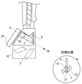
図3に示したように、回転部材20は、収容ケース10内に配置された状態では、その回転軸Aがブレードのスコアライン5と実質的に平行に延びる。また、回転部材20の先端には溝部21が形成されているが、この溝部21が、図3の円R内に示したように上下方向を向く位置を“初期位置”とする。
≪Mechanism for cutting off the
As shown in FIG. 3, in the state where the
円Rは、矢印R方向に見た場合の、回転部材20の溝部21と、ブレード6のスコアライン5との位置関係を示している。
すなわち、回転部材20は、操作レバー30によって回転するが、“初期位置”にあるとき、ブレード6を図3において上方から溝部21内に挿通させることができる。この状態で、操作レバー30を操作して回転部材20を回転させると、ブレード部分に曲げ力が加わり、スコアライン5に沿って刃先7が折り取られる。
折り取られた刃先7は、飛び散ることなく、そのままケース10内に収容され、最終的には、開閉蓋14を開けて取り出され、安全に処理される。
A circle R indicates the positional relationship between the
That is, the rotating
The
≪スプリング35≫
スプリング35は、2つの脚部35a、35bとコイル状の頭部35cを備える。頭部35cは回転部材20に外嵌され、一方の脚部35aはケース壁面に設けた穴15に嵌め込まれ、他方の脚部35bは操作レバー30の側面に設けた穴(図示せず)に嵌め込まれる。
これにより、操作レバー30はある特定の位置に向けて付勢されることとなるが、この特定の位置が上記“初期位置”となるように、各部材の形状等を設定する。すなわち、操作レバー30を操作して刃先7を折り取った後、操作する手を放すと、スプリング35の付勢力により、回転部材20は自動的に図3に示した“初期位置”に戻り、次の刃折り作業が容易となる。
このような付勢力を与える具体的な手段としては、図示した形状のスプリング35に限らず、任意の弾性部材を採用することが可能である。
≪
The
As a result, the
The specific means for applying such an urging force is not limited to the illustrated
≪アダプタ部材40≫
図2に示したアダプタ部材40は、収容ケース10に対して、挿入口11を塞ぐように着脱可能に取り付けられる。アダプタ部材40には、挿入口11よりもサイズが小さな挿入口11'が形成されている。
すなわち、アダプタ部材40を取り付けた状態では(図示せず)、よりサイズの小さいカッターナイフのブレードを挿入口11'から挿入することができる。そのときに、上に説明したのと同じように、刃先を折り取ることができるように、アダプタ部材40上での挿入口11'の形成位置を設定する。
<<
The
That is, when the
≪他の実施形態≫
図示した実施形態では、回転部材20を回転操作する操作手段として、ケース10の外部に位置する操作レバー30を採用していた。
しかしながら、本発明においては、回転部材20を回転操作する操作手段は、何らかの手法で回転部材20を回転操作し、これにより、回転部材の溝部21に挿通されたブレード部分に曲げ力を加えて破断させることができれば足りる。
<< Other Embodiments >>
In the illustrated embodiment, the
However, in the present invention, the operating means for rotating the rotating
例えば、ケース10内において、回転部材20にカム機構を設けて、これを操作手段としてもよい。挿入口11から挿入されるカッターナイフ先端部と当該カム機構(操作手段)の連携により、回転部材20を回転させる。
この場合には、図示したような手に持つタイプの収容ケース以外にも、卓上タイプの収容ケースとして構成し、机上に置かれたケースの上面に挿入口11を配置することも考えられる。
また、図2に示したスプリング35に相当する弾性手段を設けて、回転部材20を“初期位置”に付勢することが好ましい。
For example, a cam mechanism may be provided on the rotating
In this case, it is also conceivable to configure as a desktop-type storage case other than the hand-type storage case shown in the figure, and to arrange the
Further, it is preferable to provide an elastic means corresponding to the
また他の例として、回転部材20をモータ駆動で回転させるよう構成し、その駆動スイッチ(操作手段)をケース10表面にも設けてもよい。
As another example, the rotating
5 スコアライン
6 ナイフブレード
7 刃先
10 収容ケース
11、11' 挿入口
12 開口
13 透明プレート
14 開閉蓋
15 穴
17 開口
18 スリット部
20 回転部材
21 溝部
28 ピン
30 操作レバー
35 スプリング
35a、b 脚部
35c 頭部
40 アダプタ部材
A 回転軸
R 円、矢印
5
Claims (3)
ナイフブレードの先端を受け入れる挿入口(11)と、
挿入口(11)から挿入されたナイフブレード(6)が挿通される溝部(21)を備えるとともに、その回転軸(A)が当該ナイフブレードのスコアライン(5)と実質的に平行に延びるように配置された回転部材(20)と、
回転部材の溝部(21)に挿通されたブレード部分に曲げ力を加えて破断させるべく、当該回転部材(20)を回転操作する操作手段(30)と、を備えた収容ケース。 In this case, the knife blade (6) having a plurality of score lines (5) formed in parallel at a predetermined interval is broken along the score line (5) and the broken blade edge (7) is accommodated. And
An insertion slot (11) for receiving the tip of the knife blade;
The groove portion (21) into which the knife blade (6) inserted from the insertion port (11) is inserted is provided, and the rotation axis (A) thereof extends substantially parallel to the score line (5) of the knife blade. A rotating member (20) disposed in the
A storage case comprising operating means (30) for rotating the rotating member (20) so as to apply a bending force to the blade portion inserted into the groove (21) of the rotating member to cause breakage.
上記操作手段(30)は、回転部材が当該初期位置となる位置へと、弾性部材(35)で付勢されている、請求項1記載の収容ケース。 In the initial position, the rotating member (20) receives the knife blade inserted from the insertion port by the groove (21),
The storage case according to claim 1, wherein the operating means (30) is urged by an elastic member (35) to a position where the rotating member becomes the initial position.
Priority Applications (4)
| Application Number | Priority Date | Filing Date | Title |
|---|---|---|---|
| JP2011018402A JP5204860B2 (en) | 2011-01-31 | 2011-01-31 | Blade folding case |
| CA2765278A CA2765278C (en) | 2011-01-31 | 2012-01-24 | Blade snap-off holder |
| EP20120153030 EP2481533B1 (en) | 2011-01-31 | 2012-01-30 | Blade snap-off holder |
| US13/361,690 US8727195B2 (en) | 2011-01-31 | 2012-01-30 | Blade snap-off holder |
Applications Claiming Priority (1)
| Application Number | Priority Date | Filing Date | Title |
|---|---|---|---|
| JP2011018402A JP5204860B2 (en) | 2011-01-31 | 2011-01-31 | Blade folding case |
Publications (2)
| Publication Number | Publication Date |
|---|---|
| JP2012157471A true JP2012157471A (en) | 2012-08-23 |
| JP5204860B2 JP5204860B2 (en) | 2013-06-05 |
Family
ID=45557914
Family Applications (1)
| Application Number | Title | Priority Date | Filing Date |
|---|---|---|---|
| JP2011018402A Expired - Fee Related JP5204860B2 (en) | 2011-01-31 | 2011-01-31 | Blade folding case |
Country Status (4)
| Country | Link |
|---|---|
| US (1) | US8727195B2 (en) |
| EP (1) | EP2481533B1 (en) |
| JP (1) | JP5204860B2 (en) |
| CA (1) | CA2765278C (en) |
Cited By (1)
| Publication number | Priority date | Publication date | Assignee | Title |
|---|---|---|---|---|
| JP2016202576A (en) * | 2015-04-22 | 2016-12-08 | 明 永井 | Cutter knife tip folder |
Families Citing this family (4)
| Publication number | Priority date | Publication date | Assignee | Title |
|---|---|---|---|---|
| DE102019109888B3 (en) | 2019-04-15 | 2020-04-23 | Lutz Gmbh & Co. Kg | Blade container for storing and disposing of used blades |
| DE202019102148U1 (en) | 2019-04-15 | 2019-05-09 | Lutz Gmbh & Co. Kg | Blade container for storage and disposal of used blades |
| US11198228B2 (en) | 2019-11-18 | 2021-12-14 | Stanley Black & Decker, Inc. | Knife with integrated blade snapper |
| EP4019215A1 (en) * | 2020-12-23 | 2022-06-29 | Industrias Tecnológicas de Mecanización y Automatizaciòn, S.A. | Machine for cutting decorations for frustoconical bodies |
Citations (5)
| Publication number | Priority date | Publication date | Assignee | Title |
|---|---|---|---|---|
| JPS4529199Y1 (en) * | 1967-08-19 | 1970-11-10 | ||
| JPS5332500A (en) * | 1976-09-07 | 1978-03-27 | Kouji Mizukaki | Cutting edge breaking tool |
| JPH03119366U (en) * | 1990-03-16 | 1991-12-09 | ||
| JP2000140460A (en) * | 1998-11-05 | 2000-05-23 | Hiroko Hawaka | Blade snapping device for blade snapping type cutter |
| JP2006116136A (en) * | 2004-10-22 | 2006-05-11 | Nakasone Interior:Kk | Blade snapper for cutter |
Family Cites Families (13)
| Publication number | Priority date | Publication date | Assignee | Title |
|---|---|---|---|---|
| US4063481A (en) * | 1976-10-12 | 1977-12-20 | Union Carbide Corporation | Rotary cutting device |
| US4077555A (en) * | 1977-02-15 | 1978-03-07 | Jeff Adolph L | Blade-breaking apparatus |
| GB8900402D0 (en) * | 1989-01-09 | 1989-03-08 | Stanley Works Ltd | A device for breaking-off and storing used pieces of a snap-off blade |
| GB2230996B (en) * | 1989-04-25 | 1993-02-17 | Stanley Works Ltd | A snap-off blade knife |
| JPH0449053U (en) * | 1990-08-29 | 1992-04-24 | ||
| DE9320926U1 (en) * | 1993-06-29 | 1995-06-14 | Wessel Gerd | Pocket container for breaking off and picking up the pieces of cutter knife blades |
| US6000590A (en) * | 1998-04-09 | 1999-12-14 | Allen; Mary Kay | Blade holster assembly |
| DE10126978C2 (en) * | 2001-06-03 | 2003-05-22 | Klaus Spatzier | Break-off and collecting device for cut knife blade segments |
| US20050050734A1 (en) * | 2003-09-08 | 2005-03-10 | Kesinger Donald A. | Snap knife with improved safety and usability |
| DE202005003900U1 (en) * | 2005-03-10 | 2005-06-02 | Liang, Sheng Hsuan, Dali | Multi-purpose knife, comprising safe blade breaking mechanism attached to front of tool |
| JP2007252494A (en) | 2006-03-22 | 2007-10-04 | Pilot Corporation | Waste blade case with blade breaking function |
| JP5132219B2 (en) | 2007-08-09 | 2013-01-30 | 株式会社貝印刃物開発センター | Cutter blade case |
| EP2252438A4 (en) * | 2008-01-30 | 2011-03-30 | American Safety Razor | Snap-off knife |
-
2011
- 2011-01-31 JP JP2011018402A patent/JP5204860B2/en not_active Expired - Fee Related
-
2012
- 2012-01-24 CA CA2765278A patent/CA2765278C/en not_active Expired - Fee Related
- 2012-01-30 EP EP20120153030 patent/EP2481533B1/en not_active Not-in-force
- 2012-01-30 US US13/361,690 patent/US8727195B2/en not_active Expired - Fee Related
Patent Citations (5)
| Publication number | Priority date | Publication date | Assignee | Title |
|---|---|---|---|---|
| JPS4529199Y1 (en) * | 1967-08-19 | 1970-11-10 | ||
| JPS5332500A (en) * | 1976-09-07 | 1978-03-27 | Kouji Mizukaki | Cutting edge breaking tool |
| JPH03119366U (en) * | 1990-03-16 | 1991-12-09 | ||
| JP2000140460A (en) * | 1998-11-05 | 2000-05-23 | Hiroko Hawaka | Blade snapping device for blade snapping type cutter |
| JP2006116136A (en) * | 2004-10-22 | 2006-05-11 | Nakasone Interior:Kk | Blade snapper for cutter |
Cited By (1)
| Publication number | Priority date | Publication date | Assignee | Title |
|---|---|---|---|---|
| JP2016202576A (en) * | 2015-04-22 | 2016-12-08 | 明 永井 | Cutter knife tip folder |
Also Published As
| Publication number | Publication date |
|---|---|
| JP5204860B2 (en) | 2013-06-05 |
| US20120199626A1 (en) | 2012-08-09 |
| CA2765278C (en) | 2018-05-01 |
| CA2765278A1 (en) | 2012-07-31 |
| EP2481533A1 (en) | 2012-08-01 |
| EP2481533B1 (en) | 2014-01-15 |
| US8727195B2 (en) | 2014-05-20 |
Similar Documents
| Publication | Publication Date | Title |
|---|---|---|
| JP5204860B2 (en) | Blade folding case | |
| EP1747858A2 (en) | Nose hair cutter | |
| CN101298144B (en) | Eyebrow beauty device | |
| KR20050021900A (en) | Hair trimmer with rattle dampening structure | |
| JP5132219B2 (en) | Cutter blade case | |
| JP2007029382A (en) | Nose hair cutter | |
| CN108700711B (en) | Optical fiber cutter | |
| JP3117590U (en) | Headliner | |
| JP2012066001A (en) | Snap-off blade case | |
| KR101954754B1 (en) | Portable semi-automatic tape cutter | |
| JP2020058754A (en) | Blade snapping case | |
| EP2781310A2 (en) | Pneumatic tool driving assembly | |
| EP4124412A1 (en) | Stapler | |
| JP3915075B2 (en) | Tape cutter | |
| JP4403921B2 (en) | E type retaining ring removal tool | |
| JP7258384B1 (en) | cutter | |
| JP5696415B2 (en) | Cutter blade holder | |
| JP6397540B2 (en) | Cutter knife blade folding tool | |
| KR20180028225A (en) | Portable semi-automatic tape cutter | |
| JP3104656U (en) | Replaceable blade tool | |
| JP3147715U (en) | Electric nose hair cutter | |
| JP5612789B1 (en) | Tape applicator | |
| JPH081823Y2 (en) | Edge cutting device for paper sheets | |
| JP2008146892A (en) | Shutter attaching structure for card connector assembly | |
| JP2008207518A (en) | Electric pencil sharpener |
Legal Events
| Date | Code | Title | Description |
|---|---|---|---|
| TRDD | Decision of grant or rejection written | ||
| A977 | Report on retrieval |
Free format text: JAPANESE INTERMEDIATE CODE: A971007 Effective date: 20130117 |
|
| A01 | Written decision to grant a patent or to grant a registration (utility model) |
Free format text: JAPANESE INTERMEDIATE CODE: A01 Effective date: 20130122 |
|
| A61 | First payment of annual fees (during grant procedure) |
Free format text: JAPANESE INTERMEDIATE CODE: A61 Effective date: 20130215 |
|
| R150 | Certificate of patent or registration of utility model |
Ref document number: 5204860 Country of ref document: JP Free format text: JAPANESE INTERMEDIATE CODE: R150 Free format text: JAPANESE INTERMEDIATE CODE: R150 |
|
| FPAY | Renewal fee payment (event date is renewal date of database) |
Free format text: PAYMENT UNTIL: 20160222 Year of fee payment: 3 |
|
| R250 | Receipt of annual fees |
Free format text: JAPANESE INTERMEDIATE CODE: R250 |
|
| R250 | Receipt of annual fees |
Free format text: JAPANESE INTERMEDIATE CODE: R250 |
|
| R250 | Receipt of annual fees |
Free format text: JAPANESE INTERMEDIATE CODE: R250 |
|
| R250 | Receipt of annual fees |
Free format text: JAPANESE INTERMEDIATE CODE: R250 |
|
| R250 | Receipt of annual fees |
Free format text: JAPANESE INTERMEDIATE CODE: R250 |
|
| R250 | Receipt of annual fees |
Free format text: JAPANESE INTERMEDIATE CODE: R250 |
|
| LAPS | Cancellation because of no payment of annual fees |