JP2012157245A - Hydroponic culture device with container hanging member - Google Patents
Hydroponic culture device with container hanging member Download PDFInfo
- Publication number
- JP2012157245A JP2012157245A JP2011017140A JP2011017140A JP2012157245A JP 2012157245 A JP2012157245 A JP 2012157245A JP 2011017140 A JP2011017140 A JP 2011017140A JP 2011017140 A JP2011017140 A JP 2011017140A JP 2012157245 A JP2012157245 A JP 2012157245A
- Authority
- JP
- Japan
- Prior art keywords
- container
- planting
- suspension member
- liquid storage
- storage container
- Prior art date
- Legal status (The legal status is an assumption and is not a legal conclusion. Google has not performed a legal analysis and makes no representation as to the accuracy of the status listed.)
- Granted
Links
Images


Classifications
-
- Y02P60/216—
Landscapes
- Cultivation Receptacles Or Flower-Pots, Or Pots For Seedlings (AREA)
- Hydroponics (AREA)
Abstract
Description
本発明は、植物を栽培する水耕栽培装置に関する。 The present invention relates to a hydroponic cultivation apparatus for growing plants.
従来、植物を栽培する水耕栽培装置として、植栽容器と、植栽容器の植物に供給する培養液に、植栽容器を浮遊状態に収容する貯液容器との組み合わせからなる種々のものが提案されている(例えば、特許文献1参照)。 Conventionally, as a hydroponic cultivation apparatus for cultivating plants, various things consisting of a combination of a planting container and a liquid storage container that accommodates the planting container in a floating state in a culture solution supplied to the plant in the planting container It has been proposed (see, for example, Patent Document 1).
しかしながら、栽培する植物が大きく成長することにより、植物の自重によって栽培容器が沈んで当該容器に設けた培地が過湿状態となり、植物の根幹部全体が過度の水分で満たされることによって、生育状態が低下してしまう、或いは根腐れが生じて枯れてしまう。 However, when the plant to be grown grows greatly, the cultivation container sinks due to the weight of the plant, the medium provided in the container becomes overhumid, and the whole root part of the plant is filled with excessive moisture, so that the growth state Will fall, or root rot will occur and die.
本発明は、上述した技術背景に鑑み、適度な水分状態を維持して植物を栽培することができる容器吊下部材付き水耕栽培装置の提供を目的とする。 In view of the technical background described above, an object of the present invention is to provide a hydroponic cultivation apparatus with a container suspension member that can grow a plant while maintaining an appropriate moisture state.
即ち、本発明は下記[1]〜[4]に記載の構成を有する。 That is, this invention has the structure as described in following [1]-[4].
[1] 植栽容器と、前記植栽容器の植物に供給する培養液を貯留して、前記植栽容器を浮遊状態に収容する貯液容器とを備える容器吊下部材付き水耕栽培装置において、
前記貯液容器の周壁に着脱自在に構成されるとともに、前記貯液容器の周壁に取り付けられた状態で前記植栽容器を支持するように構成された容器吊下部材を備えることを特徴とする容器吊下部材付き水耕栽培装置。
[1] In a hydroponic cultivation apparatus with a container suspension member comprising a planting container and a storage container for storing a culture solution supplied to the plant in the planting container and storing the planting container in a floating state ,
The container suspension member is configured to be detachable from the peripheral wall of the liquid storage container, and includes a container suspension member configured to support the planting container in a state of being attached to the peripheral wall of the liquid storage container. Hydroponic cultivation device with container suspension member.
[2] 前記植栽容器は、底壁に通水部を有する植栽室を包囲し下向きに開口した環状フロート室が形成されてなり、
前記容器吊下部材は直線部を有し、前記直線部の一端側に前記貯液容器の周壁に掛止される掛止部が湾曲形成されてなり、前記環状フロート室の外壁下部に取り付けて前記植栽容器を支持する支持部が湾曲形成されてなることを特徴とする前項1に記載の容器吊下部材付き水耕栽培装置。
[2] The planting container is formed with an annular float chamber that surrounds a planting room having a water passage on the bottom wall and opens downward.
The container suspension member has a straight part, and a hooking part that is hooked on the peripheral wall of the liquid storage container is curved on one end side of the linear part, and is attached to the lower part of the outer wall of the annular float chamber. The hydroponic cultivation apparatus with a container suspension member according to
[3] 前記掛止部及び前記支持部の先端は、円弧を有する曲線状に形成されることを特徴とする前項2に記載の容器吊下部材付き水耕栽培装置。
[3] The hydroponic cultivation apparatus with a container suspension member according to the
[4] 前記容器吊下部材は、ばね鋼材料からなることを特徴とする前項1〜3のいずれかに記載の容器吊下部材付き水耕栽培装置。
[4] The hydroponic cultivation apparatus with a container suspension member according to any one of
上記[1]に記載の発明によれば、容器吊下部材によって植栽容器を貯液容器から吊下げることができるので、植物が成長して大きくなった場合であっても植栽容器が沈むことがなく、適度な水分状態を維持して植物を栽培することができる。 According to the invention described in [1] above, since the planting container can be suspended from the storage container by the container suspension member, the planting container sinks even when the plant grows and becomes large. The plant can be cultivated while maintaining an appropriate moisture state.
上記[2]に記載の発明によれば、容器吊下部材の一端側を貯液容器に取り付け、他端側に植栽容器を引っ掛けるだけの単純な構成で、適度な水分状態を維持して植物を栽培することができる。 According to the invention described in [2] above, with a simple configuration in which one end of the container suspension member is attached to the storage container and the planting container is hooked on the other end, an appropriate moisture state is maintained. Plants can be cultivated.
上記[3]に記載の発明によれば、掛止部の先端が丸みを帯びた形状に形成されているので、貯液容器の周壁に容器吊下部材を取り付け易い。また、支持部の先端が丸みを帯びた形状に形成されているので安全性が高い。 According to the invention described in [3] above, since the tip of the latching portion is formed in a rounded shape, it is easy to attach the container suspension member to the peripheral wall of the liquid storage container. In addition, since the tip of the support portion is formed in a rounded shape, safety is high.
上記[4]に記載の発明によれば、容器吊下部材がばね鋼材料で形成されているので、容器吊下部材を貯液容器に取り付けた場合に、容器吊下部材が貯液容器の壁面に対して垂直になるように取り付けることができ、植栽容器の容器吊下部材への取り付けが容易である。 According to the invention described in [4] above, since the container hanging member is formed of a spring steel material, when the container hanging member is attached to the liquid storage container, the container hanging member is the liquid storage container. It can be attached so as to be perpendicular to the wall surface, and it is easy to attach the planting container to the container suspension member.
以下、図面を参照して、本発明の実施形態について説明する。 Embodiments of the present invention will be described below with reference to the drawings.
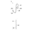
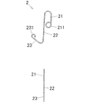
図1は、容器吊下部材2付き水耕栽培装置1について説明する説明図、図2は、図1の容器吊下部材2付き水耕栽培装置1における容器吊下部材2について説明する説明図、図3〜図5は、図1の容器吊下部材2付き水耕栽培装置1について説明する説明図である。
FIG. 1 is an explanatory view for explaining a
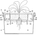
水耕栽培装置1は、植栽容器3と、前記植栽容器3の植物に供給する培養液6を貯留して、前記植栽容器3を浮遊状態に収容する貯液容器4と、を備える。植栽容器3には、培地5が収容されて使用される。
The
培地5に植物の種子や苗を載置しておくと、培地5の毛管現象により上昇させられた培養液6を種子や苗が吸収することにより植物が成長する。
When plant seeds and seedlings are placed on the
図1に示すように、貯液容器4は、下部から上部にいくに従って徐々に拡開するテーパーの有底円筒状に形成されている。
As shown in FIG. 1, the
植栽容器3は、植栽室34と、植栽室34を包囲し下向きに開口した環状フロート室33が一体形成されてなる。植栽室34の底壁31には、多数の通孔321が放射状かつ同心円状に設けられ、これら多数の通孔321が通水部32を構成する。
The
植栽室34には多孔質材料からなる培地5が収容される。培地5には、例えば、ロックウール成形品、ウレタンやフェノール等の各種発泡樹脂成形品、ブロック状やマット状等に形成された植物繊維、無機繊維等からなる成形品が用いられる。
In the
環状フロート室33は、植栽室34と一体成形されており、下向きに開口する断面コ字状に形成されるとともに、周方向に所定間隔(例えば、90度間隔)をおいて設けられた隔壁により4つの小房36に分割されている。このような小房36を備えた環状フロート室33の構成により、培養液上に浮かべた小房36に空気などの気体が充填されて浮力体となることで、別体の浮力体を必要とすることなく植栽容器3を培養液6上に浮遊させることができる。
The
環状フロート室33の外壁面は、平面視において略正方形に形成されている。環状フロート室33の外壁面の四隅は、それぞれが外方に突出する曲面状に形成された近接面332をなす。近接面332は、貯液容器4の内壁に略々沿うように形成される。隣り合う近接面332の間は、平面状に形成され、貯液容器4の内壁との間に手指の挿入が可能な間隔を有した隔離面331をなす。
The outer wall surface of the
このように貯液容器4の内壁との間に手指挿入可能な間隔が形成されているため、植栽容器3を掴み易く、貯液容器4からの出し入れを行い易い。
Thus, since the space | interval which can insert fingers is formed between the inner walls of the
植栽室34の底壁31の下方には、脚部35が円弧状に配置されている。植栽室34の底壁31に脚部35が配置されることにより、貯液容器4内の培養液6が渇水状態になったり、或いは渇水状態に近づいたりした場合にも、植栽室34の底壁31が貯液容器4の底面に当接することはない。
Below the
図3に基づいて植物を当該水耕栽培装置1で育成させる場合について説明すると、培地5を植栽室34に収容して、培地5に苗を植えるようにして置いた後、植栽容器3を貯液容器4内に入れて、脚部35を貯液容器4の底面に載置する。
The case where a plant is grown in the
続いて、培地5の上から培養液6を少しずつ掛けていき、植栽容器3が培養液6上に浮かぶまで培養液6を貯液容器4に注入する。
Subsequently, the
植栽容器3が培養液6中に浮遊した状態では、植栽室34に収容された状態の培地5の下半分が培養液6に浸かった状態であり、苗の根が短い場合には培地5の毛管現象によって苗が培養液6を吸収し、苗の根が生長して長くなっている場合には、培地5を浸している培養液6から直接吸収する。
In the state where the
苗による吸収と自然蒸発とによって培養液6の総量が減少して液面が徐々に低下するため、その都度貯液容器4に培養液6を補充するなどすればよい。貯液容器4に培養液6を補充することによって、再度植栽容器3の浮遊状態を実現できる。
Since the total amount of the
図4に示すように、栽培している植物が成長してその自重により植栽容器3が培養液6上に浮遊しなくなった場合或いは培養液6上で植栽容器3が傾いてしまう場合等には、容器吊下げ部材を用いて、植栽容器3の植物が培養液6を吸収可能な高さ位置に調整する必要がある。
As shown in FIG. 4, when the cultivated plant grows and the
容器吊下部材2は、貯液容器4の周壁41に取り付けられた状態で、植栽容器3が貯液容器4に吊下げられた状態となるように容器吊下部材2によって植栽容器3を支持するように構成されている。
The
図2に示すように、容器吊下部材2は、ばね鋼材料からなる線材を用いて形成され、植物の成長度合いに合わせて容器吊下部材2を使用することができるように、貯液容器4の周壁41に着脱自在に構成されている。
As shown in FIG. 2, the
容器吊下部材2がばね鋼材料で形成されているので、容器吊下部材2を貯液容器4に取り付けた場合に、容器吊下部材2の支持部23が貯液容器4の壁面に対して垂直になるように、本実施例では支持部23が貯液容器4の中心方向に向くように取り付けられる。容器吊下部材2がこのように取り付けられるので、植栽容器3の容器吊下部材2への取り付けが容易である。
Since the
前記容器吊下部材2は直線部22を有している。前記容器吊下部材2には、前記直線部22の一端側に前記貯液容器4の周壁41に掛止される掛止部21が湾曲形成されてなり、前記環状フロート室33の外壁下部に取り付けて前記植栽容器3を支持する支持部23が湾曲形成されてなる。
The
例えば、貯液容器4の周壁41に取り付けられる掛止部21は、貯液容器4の周壁41を内側及び外側の両方からばね力によって挟み込むような形状となっている。環状フロート室33の外壁下部に取り付けられる支持部23は、掛止部21よりも緩やかな傾斜で湾曲しており、環状フロート室33の外壁を支持部23の湾曲部分で支持し易い角度で傾斜するように構成されている。例えば、直線部22に対する支持部23の傾斜角度は、鋭角であることが好ましい。
For example, the latching
容器吊下部材2の一端側を貯液容器4に取り付け、他端側に植栽容器3を引っ掛けるだけの単純な構成で、適度な水分状態を維持して植物を栽培することができる。
Plants can be cultivated while maintaining an appropriate moisture state with a simple configuration in which one end side of the
また、容器吊下部材2に設けた掛止部21及び支持部23の先端211,231は、円弧を有する曲線状に形成されている。
Moreover, the front-end | tip 211,231 of the latching
例えば、掛止部21の先端211は、側面視が円形状になるように丸められている。このような構成により、掛止部21の先端211が丸みを帯びた形状に形成されているので、貯液容器4の周壁41に容器吊下部材2を取り付け易い。また、支持部23の先端231が丸みを帯びた形状に形成されているので安全性が高い。
For example, the
図5に基づいて、例えば成長が過度な植物を当該水耕栽培装置1で育成させる場合について説明すると、貯液容器4から植栽容器3を取り外した状態で、容器吊下部材2の掛止部21を貯液容器4の周壁41の上部縁に挿し込んで取り付ける。
Based on FIG. 5, for example, a case where a plant that grows excessively is grown in the
容器吊下部材2を複数個取り付ける場合には、容器吊下部材2同士が対向するような位置に配置すると、容器吊下部材2により吊下げられた植栽容器3が安定するため好ましい。
In the case where a plurality of
容器吊下部材2を貯液容器4の周壁41に取り付けると、植栽容器3の外壁を下方から支持するように、貯液容器4の周壁41面に対して垂直に突出した容器吊下部材2の支持部23に植栽容器3を取り付ける。
When the
植栽容器3を取り付けると、培地5の上から培養液6を少しずつ掛けていく。この際、植栽容器3の底面と培養液6面との間に空間(隙間)が設けられるように培養液6の注入量を調整する。空間(隙間)を設けて植栽容器3の高さ位置を設定することにより、植物の根腐れを防止することができる。尚、予め植栽容器3の高さ位置を考慮して培養液6が注入された貯液容器4の周壁41に容器吊下部材2を取り付け、植栽容器3を吊り下げるのであってもよい。
When the
以上説明したような容器吊下部材2付き水耕栽培装置1により、植栽容器3を容器吊下部材2によって貯液容器4から吊下げることができるので、植物が成長して大きくなった場合であっても植栽容器3が沈むことがなく、適度な水分状態を維持して植物を栽培することができる。
Since the
上述した容器吊下部材2には、防錆処理が施されていることが好ましい。また、複数の異なる大きさの容器吊下部材2を用いて、植物の成長度合いに応じて植栽容器3の高さ位置を設定変更できるように構成されることが好適である。
The
植栽容器3及び貯液容器4は、本発明の容器吊下部材2の掛止部21を着脱可能な構成の植栽容器3及び貯液容器4であれば、特に上述で説明した構成に限定されるものではない。
If the
例えば、上述した植栽容器3は、培養液6上に浮遊させる際に、別体の浮力体を小房36に設けて培養液6上を浮遊させるのであってもよい。
For example, when the above-described
また、上述した環状フロート室33は、隔壁で分割された小房36を有すものとして説明したが、この構成に限定されるものではない。例えば、環状フロート室33全体が一つのフロートとなりえる空間として形成されるのであってもよい。
Further, the
上述では、植栽容器3に脚部35を有するように説明したが、これに限定されるものではなく、環状フロート室33に挿入された浮力体を脚部35として兼用するのであってもよいし、環状フロートに脚部35を備えないものであってもよい。
In the above description, the
上述の説明中の数値については、いずれも設計事項であり、実施例に限定されるものではない。 All the numerical values in the above description are design items and are not limited to the embodiments.
以上説明した実施形態は、本発明の一例に過ぎず、本発明の作用効果を奏する範囲において具体的構成などを適宜変更設計できることは言うまでもない。 The embodiment described above is merely an example of the present invention, and it is needless to say that the specific configuration and the like can be appropriately changed and designed within the scope of the effects of the present invention.
1…水耕栽培装置
2…容器吊下部材
3…植栽容器
4…貯液容器
6…培養液
21…掛止部
22…直線部
23…支持部
31…底壁
32…通水部
33…環状フロート室
34…植栽室
41…周壁
211…先端
231…先端
DESCRIPTION OF
図4に示すように、栽培している植物が成長してその自重により植栽容器3が培養液6上に浮遊しなくなった場合或いは培養液6上で植栽容器3が傾いてしまう場合等には、容器吊下部材2を用いて、植栽容器3の植物が培養液6を吸収可能な高さ位置に調整する必要がある。
As shown in FIG. 4, when the cultivated plant grows and the
Claims (4)
前記貯液容器の周壁に着脱自在に構成されるとともに、前記貯液容器の周壁に取り付けられた状態で前記植栽容器を支持するように構成された容器吊下部材を備えることを特徴とする容器吊下部材付き水耕栽培装置。 In a hydroponic cultivation apparatus with a container suspension member comprising a planting container and a liquid storage container that stores the culture solution supplied to the plant in the planting container and accommodates the planting container in a floating state.
The container suspension member is configured to be detachable from the peripheral wall of the liquid storage container, and includes a container suspension member configured to support the planting container in a state of being attached to the peripheral wall of the liquid storage container. Hydroponic cultivation device with container suspension member.
前記容器吊下部材は直線部を有し、前記直線部の一端側に前記貯液容器の周壁に掛止される掛止部が湾曲形成されてなり、前記環状フロート室の外壁下部に取り付けて前記植栽容器を支持する支持部が湾曲形成されてなることを特徴とする請求項1に記載の容器吊下部材付き水耕栽培装置。 The planting container is formed with an annular float chamber that surrounds a planting room having a water passage on the bottom wall and opens downward.
The container suspension member has a straight part, and a hooking part that is hooked on the peripheral wall of the liquid storage container is curved on one end side of the linear part, and is attached to the lower part of the outer wall of the annular float chamber. The hydroponic cultivation apparatus with a container suspension member according to claim 1, wherein a support portion that supports the planting container is formed in a curved shape.
The said container suspension member consists of spring steel materials, The hydroponic cultivation apparatus with a container suspension member in any one of Claims 1-3 characterized by the above-mentioned.
Priority Applications (1)
| Application Number | Priority Date | Filing Date | Title |
|---|---|---|---|
| JP2011017140A JP5437285B2 (en) | 2011-01-28 | 2011-01-28 | Hydroponic cultivation equipment with container suspension member |
Applications Claiming Priority (1)
| Application Number | Priority Date | Filing Date | Title |
|---|---|---|---|
| JP2011017140A JP5437285B2 (en) | 2011-01-28 | 2011-01-28 | Hydroponic cultivation equipment with container suspension member |
Publications (2)
| Publication Number | Publication Date |
|---|---|
| JP2012157245A true JP2012157245A (en) | 2012-08-23 |
| JP5437285B2 JP5437285B2 (en) | 2014-03-12 |
Family
ID=46838337
Family Applications (1)
| Application Number | Title | Priority Date | Filing Date |
|---|---|---|---|
| JP2011017140A Expired - Fee Related JP5437285B2 (en) | 2011-01-28 | 2011-01-28 | Hydroponic cultivation equipment with container suspension member |
Country Status (1)
| Country | Link |
|---|---|
| JP (1) | JP5437285B2 (en) |
Cited By (2)
| Publication number | Priority date | Publication date | Assignee | Title |
|---|---|---|---|---|
| CN105052589A (en) * | 2015-07-30 | 2015-11-18 | 洛阳慧宁文化传播有限公司 | Floating flowerpot |
| KR20220159626A (en) * | 2021-05-26 | 2022-12-05 | (주) 아키스페이스 | Water floating hydroponic cultivation kit for both germination and seedling cultivation |
Citations (10)
| Publication number | Priority date | Publication date | Assignee | Title |
|---|---|---|---|---|
| JPS5075943U (en) * | 1973-11-21 | 1975-07-02 | ||
| JPS5127547A (en) * | 1974-09-02 | 1976-03-08 | Kubota Ltd | |
| JPS53159938U (en) * | 1977-05-20 | 1978-12-14 | ||
| JPS54160642U (en) * | 1978-04-28 | 1979-11-09 | ||
| JPS611330A (en) * | 1984-06-14 | 1986-01-07 | 新見 正 | Hydroponic apparatus above water surface |
| JPS61193745U (en) * | 1985-05-27 | 1986-12-02 | ||
| JPH0276524A (en) * | 1988-09-09 | 1990-03-15 | Kenji Ishii | Water level maintaining planter |
| JP2000051031A (en) * | 1998-06-01 | 2000-02-22 | Yoshihisa Okamoto | Pot receiver hook |
| JP2002153137A (en) * | 2000-11-24 | 2002-05-28 | ▲吉▼坂包装株式会社 | Supporting pedestal for hanging basket |
| JP2004337021A (en) * | 2003-05-13 | 2004-12-02 | Suntry Flowers Ltd | Planting device |
-
2011
- 2011-01-28 JP JP2011017140A patent/JP5437285B2/en not_active Expired - Fee Related
Patent Citations (10)
| Publication number | Priority date | Publication date | Assignee | Title |
|---|---|---|---|---|
| JPS5075943U (en) * | 1973-11-21 | 1975-07-02 | ||
| JPS5127547A (en) * | 1974-09-02 | 1976-03-08 | Kubota Ltd | |
| JPS53159938U (en) * | 1977-05-20 | 1978-12-14 | ||
| JPS54160642U (en) * | 1978-04-28 | 1979-11-09 | ||
| JPS611330A (en) * | 1984-06-14 | 1986-01-07 | 新見 正 | Hydroponic apparatus above water surface |
| JPS61193745U (en) * | 1985-05-27 | 1986-12-02 | ||
| JPH0276524A (en) * | 1988-09-09 | 1990-03-15 | Kenji Ishii | Water level maintaining planter |
| JP2000051031A (en) * | 1998-06-01 | 2000-02-22 | Yoshihisa Okamoto | Pot receiver hook |
| JP2002153137A (en) * | 2000-11-24 | 2002-05-28 | ▲吉▼坂包装株式会社 | Supporting pedestal for hanging basket |
| JP2004337021A (en) * | 2003-05-13 | 2004-12-02 | Suntry Flowers Ltd | Planting device |
Cited By (3)
| Publication number | Priority date | Publication date | Assignee | Title |
|---|---|---|---|---|
| CN105052589A (en) * | 2015-07-30 | 2015-11-18 | 洛阳慧宁文化传播有限公司 | Floating flowerpot |
| KR20220159626A (en) * | 2021-05-26 | 2022-12-05 | (주) 아키스페이스 | Water floating hydroponic cultivation kit for both germination and seedling cultivation |
| KR102609362B1 (en) * | 2021-05-26 | 2023-12-01 | (주) 아키스페이스 | Aquatic floating hydroponic cultivation kit for germination and seedling cultivation |
Also Published As
| Publication number | Publication date |
|---|---|
| JP5437285B2 (en) | 2014-03-12 |
Similar Documents
| Publication | Publication Date | Title |
|---|---|---|
| WO2004034773A9 (en) | Bottom watering-type plant cultivation device | |
| US10874063B2 (en) | Self watering bottle planter insert | |
| JP2004242501A (en) | Method for cultivating plant, tool for cultivating plant, and planting vessel | |
| KR101499320B1 (en) | Device for vertical type water culture without pump | |
| US20150289461A1 (en) | Self-watering flowerpot | |
| JP5437285B2 (en) | Hydroponic cultivation equipment with container suspension member | |
| KR100824272B1 (en) | Hydroponic culture flowerpot | |
| KR20150078750A (en) | Pot for hydroponics | |
| JP6421910B2 (en) | Hydroponics equipment | |
| US10492390B2 (en) | Hydroponic display container for flowering bulbs | |
| JP3192278U (en) | Plant growing equipment | |
| JP2015039321A (en) | Plant cultivation device | |
| JP4644306B1 (en) | Hydroponics equipment | |
| KR200469973Y1 (en) | Dual flowerpot | |
| WO2011139756A1 (en) | Method for maintaining plants | |
| KR200461692Y1 (en) | A jardiniere having humidify function | |
| KR200420128Y1 (en) | Apparatus for supplying water to flower port | |
| KR20210037534A (en) | Flowerpot unit | |
| RU2709721C1 (en) | Tray for growing plants | |
| JP2011155900A (en) | Hydroponics implement | |
| KR200278197Y1 (en) | A pot for cultivating plants | |
| JP6704024B2 (en) | Plant cultivation device, plant cultivation method and plant cultivation container | |
| JP2000245275A (en) | Hydroponic and member for planting | |
| JPH1175564A (en) | Culture container | |
| CN205755894U (en) | A kind of automatic irrigation environmentally-friendly plastic flowerpot |
Legal Events
| Date | Code | Title | Description |
|---|---|---|---|
| A977 | Report on retrieval |
Free format text: JAPANESE INTERMEDIATE CODE: A971007 Effective date: 20130207 |
|
| A131 | Notification of reasons for refusal |
Free format text: JAPANESE INTERMEDIATE CODE: A131 Effective date: 20130219 |
|
| A521 | Written amendment |
Free format text: JAPANESE INTERMEDIATE CODE: A523 Effective date: 20130328 |
|
| TRDD | Decision of grant or rejection written | ||
| A01 | Written decision to grant a patent or to grant a registration (utility model) |
Free format text: JAPANESE INTERMEDIATE CODE: A01 Effective date: 20131119 |
|
| A61 | First payment of annual fees (during grant procedure) |
Free format text: JAPANESE INTERMEDIATE CODE: A61 Effective date: 20131211 |
|
| R150 | Certificate of patent or registration of utility model |
Free format text: JAPANESE INTERMEDIATE CODE: R150 |
|
| RD02 | Notification of acceptance of power of attorney |
Free format text: JAPANESE INTERMEDIATE CODE: R3D02 |
|
| R250 | Receipt of annual fees |
Free format text: JAPANESE INTERMEDIATE CODE: R250 |
|
| LAPS | Cancellation because of no payment of annual fees |