JP2012157201A - Electric vehicle charging device, electric vehicle charging method, program, and recording media - Google Patents
Electric vehicle charging device, electric vehicle charging method, program, and recording media Download PDFInfo
- Publication number
- JP2012157201A JP2012157201A JP2011015667A JP2011015667A JP2012157201A JP 2012157201 A JP2012157201 A JP 2012157201A JP 2011015667 A JP2011015667 A JP 2011015667A JP 2011015667 A JP2011015667 A JP 2011015667A JP 2012157201 A JP2012157201 A JP 2012157201A
- Authority
- JP
- Japan
- Prior art keywords
- power
- charging
- electric vehicle
- electric
- input
- Prior art date
- Legal status (The legal status is an assumption and is not a legal conclusion. Google has not performed a legal analysis and makes no representation as to the accuracy of the status listed.)
- Granted
Links
Images


Classifications
-
- H—ELECTRICITY
- H01—ELECTRIC ELEMENTS
- H01M—PROCESSES OR MEANS, e.g. BATTERIES, FOR THE DIRECT CONVERSION OF CHEMICAL ENERGY INTO ELECTRICAL ENERGY
- H01M10/00—Secondary cells; Manufacture thereof
- H01M10/42—Methods or arrangements for servicing or maintenance of secondary cells or secondary half-cells
- H01M10/44—Methods for charging or discharging
-
- B—PERFORMING OPERATIONS; TRANSPORTING
- B60—VEHICLES IN GENERAL
- B60L—PROPULSION OF ELECTRICALLY-PROPELLED VEHICLES; SUPPLYING ELECTRIC POWER FOR AUXILIARY EQUIPMENT OF ELECTRICALLY-PROPELLED VEHICLES; ELECTRODYNAMIC BRAKE SYSTEMS FOR VEHICLES IN GENERAL; MAGNETIC SUSPENSION OR LEVITATION FOR VEHICLES; MONITORING OPERATING VARIABLES OF ELECTRICALLY-PROPELLED VEHICLES; ELECTRIC SAFETY DEVICES FOR ELECTRICALLY-PROPELLED VEHICLES
- B60L53/00—Methods of charging batteries, specially adapted for electric vehicles; Charging stations or on-board charging equipment therefor; Exchange of energy storage elements in electric vehicles
- B60L53/60—Monitoring or controlling charging stations
- B60L53/63—Monitoring or controlling charging stations in response to network capacity
-
- H—ELECTRICITY
- H02—GENERATION; CONVERSION OR DISTRIBUTION OF ELECTRIC POWER
- H02J—CIRCUIT ARRANGEMENTS OR SYSTEMS FOR SUPPLYING OR DISTRIBUTING ELECTRIC POWER; SYSTEMS FOR STORING ELECTRIC ENERGY
- H02J3/00—Circuit arrangements for ac mains or ac distribution networks
- H02J3/12—Circuit arrangements for ac mains or ac distribution networks for adjusting voltage in ac networks by changing a characteristic of the network load
- H02J3/14—Circuit arrangements for ac mains or ac distribution networks for adjusting voltage in ac networks by changing a characteristic of the network load by switching loads on to, or off from, network, e.g. progressively balanced loading
-
- H—ELECTRICITY
- H02—GENERATION; CONVERSION OR DISTRIBUTION OF ELECTRIC POWER
- H02J—CIRCUIT ARRANGEMENTS OR SYSTEMS FOR SUPPLYING OR DISTRIBUTING ELECTRIC POWER; SYSTEMS FOR STORING ELECTRIC ENERGY
- H02J3/00—Circuit arrangements for ac mains or ac distribution networks
- H02J3/28—Arrangements for balancing of the load in a network by storage of energy
- H02J3/32—Arrangements for balancing of the load in a network by storage of energy using batteries with converting means
- H02J3/322—Arrangements for balancing of the load in a network by storage of energy using batteries with converting means the battery being on-board an electric or hybrid vehicle, e.g. vehicle to grid arrangements [V2G], power aggregation, use of the battery for network load balancing, coordinated or cooperative battery charging
-
- H—ELECTRICITY
- H02—GENERATION; CONVERSION OR DISTRIBUTION OF ELECTRIC POWER
- H02J—CIRCUIT ARRANGEMENTS OR SYSTEMS FOR SUPPLYING OR DISTRIBUTING ELECTRIC POWER; SYSTEMS FOR STORING ELECTRIC ENERGY
- H02J7/00—Circuit arrangements for charging or depolarising batteries or for supplying loads from batteries
- H02J7/02—Circuit arrangements for charging or depolarising batteries or for supplying loads from batteries for charging batteries from ac mains by converters
-
- H—ELECTRICITY
- H01—ELECTRIC ELEMENTS
- H01M—PROCESSES OR MEANS, e.g. BATTERIES, FOR THE DIRECT CONVERSION OF CHEMICAL ENERGY INTO ELECTRICAL ENERGY
- H01M2220/00—Batteries for particular applications
- H01M2220/20—Batteries in motive systems, e.g. vehicle, ship, plane
-
- H—ELECTRICITY
- H02—GENERATION; CONVERSION OR DISTRIBUTION OF ELECTRIC POWER
- H02J—CIRCUIT ARRANGEMENTS OR SYSTEMS FOR SUPPLYING OR DISTRIBUTING ELECTRIC POWER; SYSTEMS FOR STORING ELECTRIC ENERGY
- H02J2207/00—Indexing scheme relating to details of circuit arrangements for charging or depolarising batteries or for supplying loads from batteries
- H02J2207/20—Charging or discharging characterised by the power electronics converter
-
- H—ELECTRICITY
- H02—GENERATION; CONVERSION OR DISTRIBUTION OF ELECTRIC POWER
- H02J—CIRCUIT ARRANGEMENTS OR SYSTEMS FOR SUPPLYING OR DISTRIBUTING ELECTRIC POWER; SYSTEMS FOR STORING ELECTRIC ENERGY
- H02J2310/00—The network for supplying or distributing electric power characterised by its spatial reach or by the load
- H02J2310/10—The network having a local or delimited stationary reach
- H02J2310/12—The local stationary network supplying a household or a building
- H02J2310/14—The load or loads being home appliances
-
- Y—GENERAL TAGGING OF NEW TECHNOLOGICAL DEVELOPMENTS; GENERAL TAGGING OF CROSS-SECTIONAL TECHNOLOGIES SPANNING OVER SEVERAL SECTIONS OF THE IPC; TECHNICAL SUBJECTS COVERED BY FORMER USPC CROSS-REFERENCE ART COLLECTIONS [XRACs] AND DIGESTS
- Y02—TECHNOLOGIES OR APPLICATIONS FOR MITIGATION OR ADAPTATION AGAINST CLIMATE CHANGE
- Y02E—REDUCTION OF GREENHOUSE GAS [GHG] EMISSIONS, RELATED TO ENERGY GENERATION, TRANSMISSION OR DISTRIBUTION
- Y02E60/00—Enabling technologies; Technologies with a potential or indirect contribution to GHG emissions mitigation
- Y02E60/10—Energy storage using batteries
-
- Y—GENERAL TAGGING OF NEW TECHNOLOGICAL DEVELOPMENTS; GENERAL TAGGING OF CROSS-SECTIONAL TECHNOLOGIES SPANNING OVER SEVERAL SECTIONS OF THE IPC; TECHNICAL SUBJECTS COVERED BY FORMER USPC CROSS-REFERENCE ART COLLECTIONS [XRACs] AND DIGESTS
- Y02—TECHNOLOGIES OR APPLICATIONS FOR MITIGATION OR ADAPTATION AGAINST CLIMATE CHANGE
- Y02T—CLIMATE CHANGE MITIGATION TECHNOLOGIES RELATED TO TRANSPORTATION
- Y02T10/00—Road transport of goods or passengers
- Y02T10/60—Other road transportation technologies with climate change mitigation effect
- Y02T10/70—Energy storage systems for electromobility, e.g. batteries
-
- Y—GENERAL TAGGING OF NEW TECHNOLOGICAL DEVELOPMENTS; GENERAL TAGGING OF CROSS-SECTIONAL TECHNOLOGIES SPANNING OVER SEVERAL SECTIONS OF THE IPC; TECHNICAL SUBJECTS COVERED BY FORMER USPC CROSS-REFERENCE ART COLLECTIONS [XRACs] AND DIGESTS
- Y02—TECHNOLOGIES OR APPLICATIONS FOR MITIGATION OR ADAPTATION AGAINST CLIMATE CHANGE
- Y02T—CLIMATE CHANGE MITIGATION TECHNOLOGIES RELATED TO TRANSPORTATION
- Y02T10/00—Road transport of goods or passengers
- Y02T10/60—Other road transportation technologies with climate change mitigation effect
- Y02T10/7072—Electromobility specific charging systems or methods for batteries, ultracapacitors, supercapacitors or double-layer capacitors
-
- Y—GENERAL TAGGING OF NEW TECHNOLOGICAL DEVELOPMENTS; GENERAL TAGGING OF CROSS-SECTIONAL TECHNOLOGIES SPANNING OVER SEVERAL SECTIONS OF THE IPC; TECHNICAL SUBJECTS COVERED BY FORMER USPC CROSS-REFERENCE ART COLLECTIONS [XRACs] AND DIGESTS
- Y02—TECHNOLOGIES OR APPLICATIONS FOR MITIGATION OR ADAPTATION AGAINST CLIMATE CHANGE
- Y02T—CLIMATE CHANGE MITIGATION TECHNOLOGIES RELATED TO TRANSPORTATION
- Y02T90/00—Enabling technologies or technologies with a potential or indirect contribution to GHG emissions mitigation
- Y02T90/10—Technologies relating to charging of electric vehicles
- Y02T90/12—Electric charging stations
-
- Y—GENERAL TAGGING OF NEW TECHNOLOGICAL DEVELOPMENTS; GENERAL TAGGING OF CROSS-SECTIONAL TECHNOLOGIES SPANNING OVER SEVERAL SECTIONS OF THE IPC; TECHNICAL SUBJECTS COVERED BY FORMER USPC CROSS-REFERENCE ART COLLECTIONS [XRACs] AND DIGESTS
- Y02—TECHNOLOGIES OR APPLICATIONS FOR MITIGATION OR ADAPTATION AGAINST CLIMATE CHANGE
- Y02T—CLIMATE CHANGE MITIGATION TECHNOLOGIES RELATED TO TRANSPORTATION
- Y02T90/00—Enabling technologies or technologies with a potential or indirect contribution to GHG emissions mitigation
- Y02T90/10—Technologies relating to charging of electric vehicles
- Y02T90/16—Information or communication technologies improving the operation of electric vehicles
- Y02T90/167—Systems integrating technologies related to power network operation and communication or information technologies for supporting the interoperability of electric or hybrid vehicles, i.e. smartgrids as interface for battery charging of electric vehicles [EV] or hybrid vehicles [HEV]
-
- Y—GENERAL TAGGING OF NEW TECHNOLOGICAL DEVELOPMENTS; GENERAL TAGGING OF CROSS-SECTIONAL TECHNOLOGIES SPANNING OVER SEVERAL SECTIONS OF THE IPC; TECHNICAL SUBJECTS COVERED BY FORMER USPC CROSS-REFERENCE ART COLLECTIONS [XRACs] AND DIGESTS
- Y04—INFORMATION OR COMMUNICATION TECHNOLOGIES HAVING AN IMPACT ON OTHER TECHNOLOGY AREAS
- Y04S—SYSTEMS INTEGRATING TECHNOLOGIES RELATED TO POWER NETWORK OPERATION, COMMUNICATION OR INFORMATION TECHNOLOGIES FOR IMPROVING THE ELECTRICAL POWER GENERATION, TRANSMISSION, DISTRIBUTION, MANAGEMENT OR USAGE, i.e. SMART GRIDS
- Y04S10/00—Systems supporting electrical power generation, transmission or distribution
- Y04S10/12—Monitoring or controlling equipment for energy generation units, e.g. distributed energy generation [DER] or load-side generation
- Y04S10/126—Monitoring or controlling equipment for energy generation units, e.g. distributed energy generation [DER] or load-side generation the energy generation units being or involving electric vehicles [EV] or hybrid vehicles [HEV], i.e. power aggregation of EV or HEV, vehicle to grid arrangements [V2G]
-
- Y—GENERAL TAGGING OF NEW TECHNOLOGICAL DEVELOPMENTS; GENERAL TAGGING OF CROSS-SECTIONAL TECHNOLOGIES SPANNING OVER SEVERAL SECTIONS OF THE IPC; TECHNICAL SUBJECTS COVERED BY FORMER USPC CROSS-REFERENCE ART COLLECTIONS [XRACs] AND DIGESTS
- Y04—INFORMATION OR COMMUNICATION TECHNOLOGIES HAVING AN IMPACT ON OTHER TECHNOLOGY AREAS
- Y04S—SYSTEMS INTEGRATING TECHNOLOGIES RELATED TO POWER NETWORK OPERATION, COMMUNICATION OR INFORMATION TECHNOLOGIES FOR IMPROVING THE ELECTRICAL POWER GENERATION, TRANSMISSION, DISTRIBUTION, MANAGEMENT OR USAGE, i.e. SMART GRIDS
- Y04S30/00—Systems supporting specific end-user applications in the sector of transportation
- Y04S30/10—Systems supporting the interoperability of electric or hybrid vehicles
- Y04S30/12—Remote or cooperative charging
Abstract
Description
本発明は、例えば一般家庭において、電気自動車の電池を充電するための電力供給を制御する電気自動車充電装置、電気自動車充電方法、プログラムおよび記録媒体に関する。 The present invention relates to an electric vehicle charging apparatus, an electric vehicle charging method, a program, and a recording medium that control power supply for charging a battery of an electric vehicle, for example, in a general household.
近年、動力源として内燃機関に代えてモータを使用する電気自動車が開発されている。電気自動車は、電源として蓄電池を使用し、蓄電池からの電力供給によりモータを駆動して走行する。このため、内燃機関と比較して、エネルギー費用が安価、エネルギー効率が高い、騒音が極めて少ない、走行時に排気ガスを出さないなど、多数の利点を有している。 In recent years, an electric vehicle using a motor as a power source instead of an internal combustion engine has been developed. An electric vehicle uses a storage battery as a power source and travels by driving a motor by supplying power from the storage battery. For this reason, compared with an internal combustion engine, it has many advantages such as low energy cost, high energy efficiency, extremely low noise, and no exhaust gas when traveling.
電気自動車の蓄電池は、特許文献1に記載されているように、例えば電力会社から住宅用に供給されている電力を利用して充電することができる。一方、電力会社との契約により住宅に契約電力が設定されている場合には、電気料金の抑制の面から、その住宅での消費電力を契約電力以内に収めることが求められる。この点に関し、例えば特許文献2には、住宅内電力負荷への供給電力と電気自動車の蓄電池の充電電力との和が、住宅に供給される電力の許容値を超えないように、電気自動車の蓄電池の充電用電力を制御する構成が開示されている。
As described in
電気自動車へのエネルギーの補給、すなわち蓄電池への充電については、例えばガソリン自動車へのガソリンの補給の場合と比較して、長時間を要する。このため、電気自動車の充電装置では、例えば、通常の低速充電モードによる低速充電と高速充電モードによる高速充電とをユーザが選択できるようになっているものがある。通常、低速充電モードは、蓄電池の充電時間に余裕があるときに選択され、高速充電モードは、蓄電池の充電時間に余裕がないとき、すなわち電気自動車の使用予定時刻が迫っているときに選択される。 Replenishment of energy to an electric vehicle, that is, charging of a storage battery, takes a long time compared to, for example, replenishment of gasoline to a gasoline vehicle. For this reason, some electric vehicle charging devices allow the user to select, for example, low-speed charging in the normal low-speed charging mode and high-speed charging in the high-speed charging mode. Normally, the low-speed charging mode is selected when there is room in the charging time of the storage battery, and the high-speed charging mode is selected when there is no room in the charging time of the storage battery, that is, when the scheduled use time of the electric vehicle is approaching. The
ここで、低速充電モードは単位時間当たりの供給電力が少なく、高速充電モードは単位時間当たりの供給電力が多くなる。したがって、高速充電モードによる蓄電池の充電は、低速充電モードよりも多くの電力が必要となる。 Here, the low speed charging mode has a small supply power per unit time, and the high speed charging mode has a large supply power per unit time. Therefore, charging the storage battery in the fast charge mode requires more power than in the slow charge mode.
しかしながら、特許文献2に記載の発明では、住宅に供給される電力の許容値を超えないように、電気自動車の蓄電池の充電用電力を制御する構成であるため、住宅内電力負荷への供給電力が多い場合には、電気自動車の蓄電池の充電に必要な電力を確保することができない。このため、高速充電モードを選択した場合であっても、蓄電池に対して十分に高速な充電が行えず、ユーザが希望する時間内に蓄電池に対して所定量の充電を完了できない恐れがある。
However, in the invention described in
この問題は、低速充電モードによる充電方式と高速充電モードによる充電方式とを選択できる電気自動車充電装置に限らず、電気自動車を充電する電気自動車充電装置において起こり得るものである。 This problem is not limited to an electric vehicle charging apparatus that can select a charging method based on the low-speed charging mode and a charging method based on the high-speed charging mode, and may occur in an electric vehicle charging device that charges an electric vehicle.
したがって、本発明は、契約電力が設定されている状況下において、電気自動車の蓄電池に対しての充電を迅速に行うことができる電気自動車充電装置、電気自動車充電方法、プログラムおよび記録媒体の提供を目的としている。 Therefore, the present invention provides an electric vehicle charging device, an electric vehicle charging method, a program, and a recording medium that can quickly charge a storage battery of an electric vehicle under a situation where contract power is set. It is aimed.
上記の課題を解決するために、本発明の電気自動車充電装置は、受電設備を介して入力される入力電力に、使用する電力の上限値として使用電力上限値が設定され、前記使用電力上限値以下の電力が少なくとも住宅設置電気機器への供給電力と電気自動車への充電電力とに振り分けられ、前記電気自動車への充電電力を使用して、充電器により電気自動車の蓄電池を充電する電気自動車充電装置において、前記充電器による前記蓄電池に対しての充電優先動作による充電動作の場合に、前記電気自動車への充電電力として設定された電力量を確保するように、前記住宅設置電気機器への供給電力を制御する制御部を備えている構成である。 In order to solve the above-described problems, the electric vehicle charging device of the present invention is configured such that an input power upper limit value is set as an upper limit value of power to be used for input power input via power receiving equipment, Electric vehicle charging in which the following electric power is divided into at least power supplied to electric equipment installed in a house and electric power charged to an electric vehicle, and the electric vehicle storage battery is charged by a charger using the electric power charged to the electric vehicle. In the apparatus, in the case of the charging operation by the charging priority operation for the storage battery by the charger, the supply to the house-installed electric device so as to secure the electric energy set as the charging electric power to the electric vehicle It is the structure provided with the control part which controls electric power.
また、本発明の電気自動車充電方法は、受電設備を介して入力される入力電力に、使用する電力の上限値として使用電力上限値が設定され、前記使用電力上限値以下の電力が少なくとも住宅設置電気機器への供給電力と電気自動車への充電電力とに振り分けられ、前記電気自動車への充電電力を使用して、充電器により電気自動車の蓄電池を充電する電気自動車充電方法において、前記充電器による前記蓄電池に対しての充電優先動作による充電動作の場合に、前記電気自動車への充電電力として設定された電力量を確保するように、前記住宅設置電気機器への供給電力を制御する制御工程を備えている構成である。 Further, in the electric vehicle charging method of the present invention, a power usage upper limit value is set as an upper power power value to be used for input power input via a power receiving facility, and at least a power less than the power usage upper limit value is installed in a house. In an electric vehicle charging method in which electric battery storage battery is charged with a charger using electric power charged to the electric vehicle and distributed to electric power supplied to the electric device and electric power charged to the electric vehicle. In the case of a charging operation based on a charge priority operation for the storage battery, a control step of controlling the power supplied to the house-installed electrical device so as to ensure the amount of power set as the charging power for the electric vehicle. It is the composition which is provided.
上記の構成によれば、受電設備、例えば分電盤を介して入力される入力電力には、使用する電力の上限値として使用電力上限値、例えば契約電力が設定されている。したがって、使用電力上限値以下の電力が少なくとも住宅設置電気機器への供給電力と電気自動車への充電電力とに振り分けられ、電気自動車への充電電力を使用して、充電器により電気自動車の蓄電池の充電が行われる。 According to the above configuration, a power use upper limit value, for example, contract power is set as an upper limit value of power to be used for input power input via a power receiving facility, for example, a distribution board. Therefore, the power below the upper limit of power usage is distributed at least to the power supplied to the electric equipment installed in the house and the electric power charged to the electric vehicle, and the charger uses the electric power charged to the electric vehicle to Charging is performed.
制御部は(制御工程では)、充電器により電気自動車の蓄電池を充電優先動作により充電する場合に、電気自動車への充電電力として設定された電力量を確保するように、住宅設置電気機器への供給電力を制御する。 The control unit (in the control process), when charging the storage battery of the electric vehicle with the charger by the charge priority operation, in order to ensure the amount of power set as the charging power for the electric vehicle, Control the power supply.
これにより、使用電力上限値が設定されている条件下において、蓄電池に対しての充電を迅速に行うことができる。 Thereby, the charge with respect to a storage battery can be performed rapidly on the conditions in which the electric power use upper limit is set.
本発明の電気自動車充電装置は、受電設備を介して入力される入力電力に、使用する電力の上限値として使用電力上限値が設定され、前記使用電力上限値以下の電力が少なくとも住宅設置電気機器への供給電力と電気自動車への充電電力とに振り分けられ、前記電気自動車への充電電力を使用して、充電器により電気自動車の蓄電池を充電する電気自動車充電装置において、前記充電器による充電動作として、低速充電モードによる充電動作、または低速充電モードよりも単位時間当たりの電力供給量が多くなる充電優先動作としての高速充電モードによる充電動作を選択可能であり、前記高速充電モードによる充電動作の場合に、前記低速充電モードによる充電動作の場合よりも、前記住宅設置電気機器への供給電力が削減され、前記電気自動車への充電電力が増加するように、前記住宅設置電気機器への供給電力を制御する制御部を備えていることを特徴としている。 In the electric vehicle charging device of the present invention, a power usage upper limit value is set as an upper limit value of power to be used for input power input via a power receiving facility, and at least power equal to or lower than the power usage upper limit value is installed in a residential electrical device. In an electric vehicle charging apparatus that uses an electric vehicle charging power that is distributed between electric power supplied to the electric vehicle and charging electric power to the electric vehicle and uses the charging electric power to the electric vehicle, a charging operation by the charger The charging operation in the low-speed charging mode or the charging operation in the high-speed charging mode as the charging priority operation in which the amount of power supply per unit time is larger than that in the low-speed charging mode can be selected. In the case, the electric power supplied to the house-installed electric device is reduced as compared with the case of the charging operation in the low-speed charging mode, and the electric As the charging power to dynamic vehicle increases, it is characterized in that it comprises a control unit for controlling the power supplied to the house installation electrical device.
また、本発明の電気自動車充電方法は、受電設備を介して入力される入力電力に、使用する電力の上限値として使用電力上限値が設定され、前記使用電力上限値以下の電力が少なくとも住宅設置電気機器への供給電力と電気自動車への充電電力とに振り分けられ、前
記電気自動車への充電電力を使用して、充電器により電気自動車の蓄電池を充電する電気自動車充電方法において、前記充電器による充電動作として、低速充電モードによる充電動作、または低速充電モードよりも単位時間当たりの電力供給量が多くなる充電優先動作としての高速充電モードによる充電動作を選択可能であり、前記高速充電モードによる充電動作の場合に、前記低速充電モードによる充電動作の場合よりも、前記住宅設置電気機器への供給電力が削減され、前記電気自動車への充電電力が増加するように、前記住宅設置電気機器への供給電力を制御する制御工程を備えていることを特徴としている。
Further, in the electric vehicle charging method of the present invention, a power usage upper limit value is set as an upper power power value to be used for input power input via a power receiving facility, and at least a power less than the power usage upper limit value is installed in a house. In an electric vehicle charging method in which electric battery storage battery is charged with a charger using electric power charged to the electric vehicle and distributed to electric power supplied to the electric device and electric power charged to the electric vehicle. The charging operation can be selected from a charging operation in a low-speed charging mode, or a charging operation in a high-speed charging mode as a charging priority operation in which a power supply amount per unit time is larger than that in the low-speed charging mode. In the case of operation, compared with the case of the charging operation in the low-speed charging mode, the power supply to the house-installed electrical equipment is reduced. As the charging power to the electric vehicle increases, it is characterized in that it comprises a control step of controlling the power supplied to the house installation electrical device.
上記の構成によれば、受電設備、例えば分電盤を介して入力される入力電力には、使用する電力の上限値として使用電力上限値、例えば契約電力が設定されている。したがって、使用電力上限値以下の電力が少なくとも住宅設置電気機器への供給電力と電気自動車への充電電力とに振り分けられ、電気自動車への充電電力を使用して、充電器により電気自動車の蓄電池の充電が行われる。 According to the above configuration, a power use upper limit value, for example, contract power is set as an upper limit value of power to be used for input power input via a power receiving facility, for example, a distribution board. Therefore, the power below the upper limit of power usage is distributed at least to the power supplied to the electric equipment installed in the house and the electric power charged to the electric vehicle, and the charger uses the electric power charged to the electric vehicle to Charging is performed.
充電器による充電動作としては、低速充電モードによる充電動作、または低速充電モードよりも単位時間当たりの電力供給量が多くなる充電優先動作としての高速充電モードによる充電動作を選択可能である。制御部は(制御工程では)、高速充電モードによる充電動作の場合に、低速充電モードによる充電動作の場合よりも、住宅設置電気機器への供給電力が削減され、電気自動車への充電電力が増加するように、住宅設置電気機器への供給電力を制御する。 As the charging operation by the charger, a charging operation in the low-speed charging mode or a charging operation in the high-speed charging mode as a charging priority operation in which the amount of power supply per unit time is larger than that in the low-speed charging mode can be selected. The control unit (in the control process) reduces the power supplied to the electrical equipment installed in the house and increases the power to charge the electric vehicle when charging in the high-speed charging mode than when charging in the low-speed charging mode. In this way, the power supplied to the electrical equipment installed in the house is controlled.
これにより、使用電力上限値が設定されている条件下において、高速充電モードによる蓄電池に対しての充電を適切に、すなわち迅速に行うことができる。 Thereby, it is possible to charge the storage battery in the high-speed charging mode appropriately, that is, quickly, under the condition where the power usage upper limit value is set.
上記の電気自動車充電装置において、前記制御部は、前記充電優先動作において、前記受電設備に接続されている住宅設置電気機器の消費電力が抑制されるように住宅設置電気機器を制御する構成であってもよい。 In the above-described electric vehicle charging apparatus, the control unit is configured to control the home-installed electrical device so that power consumption of the home-installed electrical device connected to the power receiving facility is suppressed in the charge priority operation. May be.
上記の構成によれば、充電器により電気自動車の蓄電池を充電優先動作により充電する場合、例えば高速充電モードにより充電する場合に、受電設備に接続されている住宅設置電気機器の消費電力が抑制されるように住宅設置電気機器が制御される。したがって、例えば電力削減対象電気機器毎に消費電力の抑制量を設定するといったように、住宅設置電気機器の消費電力の抑制に対して、柔軟な制御が可能となる。 According to said structure, when charging the storage battery of an electric vehicle by charge priority operation | movement with a charger, for example, when charging by a high-speed charge mode, the power consumption of the residential installation electrical equipment connected to the power receiving equipment is suppressed. In this way, the electrical equipment installed in the house is controlled. Therefore, for example, a flexible control can be performed with respect to the suppression of the power consumption of the electrical equipment installed in the house, such as setting an amount of suppression of the power consumption for each electric device targeted for power reduction.
上記の電気自動車充電装置は、入力装置と、前記入力装置からの入力情報を記憶する記憶装置とを備え、前記記憶装置は、複数の前記住宅設置電気機器のうちから前記入力装置からの入力により指定された電力削減対象電気機器を記憶し、前記制御部は、前記充電優先動作において、前記電力削減対象電気機器に対して、消費電力が抑制されるように制御する構成としてもよい。 The electric vehicle charging device includes an input device and a storage device that stores input information from the input device, and the storage device receives an input from the input device from among the plurality of house-installed electrical devices. The designated power reduction target electrical device may be stored, and the control unit may control the power reduction target electrical device so that power consumption is suppressed in the charge priority operation.
上記の構成によれば、電力削減対象電気機器をユーザが入力装置を操作して指定することができる。これにより、ユーザの希望を反映して、適当な住宅設置電気機器を電力削減対象電気機器として設定することができる。 According to said structure, a user can designate the electric appliance for electric power reduction by operating an input device. Thereby, it is possible to set an appropriate home-installed electrical device as a power reduction target electrical device reflecting the user's wishes.
上記の電気自動車充電装置において、前記記憶装置は、複数の前記住宅設置電気機器のうちから前記入力装置からの入力により指定された、電力追加削減対象電気機器および前記電力追加削減対象電気機器としての優先順位を記憶し、前記制御部は、前記充電優先動作において、前記入力装置から前記充電電力の追加要求が入力された場合に、前記充電電力が前記追加要求に応じた値となるまで、前記優先順位に従って前記電力追加削減対象電気機器への供給電力が削減されるように、前記電力追加削減対象電気機器を制御する構成
としてもよい。
In the above-described electric vehicle charging device, the storage device is designated as an electric power addition reduction target electric device and the electric power addition reduction target electric device specified by an input from the input device among a plurality of the house-installed electric devices. In the charge priority operation, the control unit stores the priority, and when the charge power addition request is input from the input device, until the charge power becomes a value corresponding to the addition request, It is good also as a structure which controls the said electric power addition reduction object electric device so that the electric power supplied to the said electric power addition reduction object electric device may be reduced according to a priority.
上記の構成によれば、入力装置から充電電力の追加要求が入力された場合には、充電電力が追加要求に応じた値となるまで、ユーザにより予め設定された優先順位に従って電力追加削減対象電気機器への供給電力が削減されるように、電力追加削減対象電気機器が制御される。これにより、充電器により電気自動車の蓄電池を充電優先動作により充電する際に、例えば高速充電モードにより充電する際に、充電電力の追加要求が生じた場合には、ユーザの希望を反映した優先順位に従って電力追加削減対象電気機器に対する消費電力削減のための制御を行うことができる。 According to the above configuration, when a charge power addition request is input from the input device, the power addition reduction target electricity is added according to the priority set in advance by the user until the charge power reaches a value corresponding to the addition request. The electric power reduction target electric device is controlled so that the power supplied to the device is reduced. Thereby, when charging the storage battery of the electric vehicle by the charger with the charge priority operation, for example, when charging in the fast charge mode, when a request for adding charging power occurs, the priority order reflecting the user's wishes Accordingly, it is possible to perform control for reducing power consumption with respect to the electric power addition target electric appliance.
上記の電気自動車充電装置において、前記住宅設置電気機器は、配線遮断器を介して前記受電設備と接続され、前記制御部は、前記充電優先動作での前記住宅設置電気機器の消費電力を抑制する制御において、配線遮断器を遮断させる構成としてもよい。 In the electric vehicle charging apparatus, the house-installed electric device is connected to the power receiving facility via a wiring breaker, and the control unit suppresses power consumption of the house-installed electric device in the charge priority operation. In control, it is good also as a structure which interrupts | blocks a wiring breaker.
上記の構成によれば、充電器により電気自動車の蓄電池を充電優先動作により充電する場合、例えば高速充電モードにより充電する場合の住宅設置電気機器の消費電力を抑制する制御においては、配線遮断器が遮断される。したがって、電気自動車の蓄電池を充電する場合において、簡単な制御にて住宅設置電気機器の消費電力を抑制することができる。 According to the above configuration, in the case of charging the storage battery of the electric vehicle by the charger with the charge priority operation, for example, in the control for suppressing the power consumption of the home-installed electric device when charging in the high-speed charging mode, the wiring breaker is Blocked. Therefore, when charging the storage battery of an electric vehicle, the power consumption of the house-installed electrical device can be suppressed with simple control.
上記の電気自動車充電装置は、入力装置と、前記入力装置からの入力情報を記憶する記憶装置とを備え、前記記憶装置は、複数の前記配線遮断器のうちから前記入力装置からの入力により指定された遮断対象配線遮断器を記憶し、前記制御部は、前記充電優先動作での前記住宅設置電気機器の消費電力を抑制する制御において、前記遮断対象配線遮断器を遮断させる構成としてもよい。 The electric vehicle charging device includes an input device and a storage device that stores input information from the input device, and the storage device is designated by an input from the input device from among the plurality of wiring breakers. It is good also as a structure which memorize | stores the made interruption | blocking object circuit breaker, and the said control part interrupts | blocks the said interruption | blocking object circuit breaker in control which suppresses the power consumption of the said house installation electrical equipment in the said charge priority operation | movement.
上記の構成によれば、ユーザは、充電器により電気自動車の蓄電池を充電優先動作により充電する場合、例えば高速充電モードにより充電する場合の遮断対象配線遮断器を、配線遮断器に接続されている住宅設置電気機器を確認しながら、入力装置を操作して指定することができる。これにより、ユーザの希望を反映して、適当な配線遮断器を遮断対象配線遮断器として設定することができる。 According to said structure, the user is connecting the interruption | blocking object circuit breaker in the case of charging by the high-speed charge mode, for example, when charging the storage battery of an electric vehicle with a charger with charge priority operation to the wiring breaker. It is possible to specify by operating the input device while checking the electrical equipment installed in the house. Accordingly, an appropriate wiring breaker can be set as a breaking target wiring breaker reflecting the user's wishes.
上記の電気自動車充電装置において、前記記憶装置は、複数の前記住宅設置電気機器のうちから前記入力装置からの入力により指定された、追加遮断対象配線遮断器および前記追加遮断対象配線遮断器としての優先順位を記憶し、前記制御部は、前記充電優先動作において、前記入力装置から前記充電電力の追加要求が入力された場合に、前記充電電力が前記追加要求に応じた値となるまで、前記優先順位に従って前記追加遮断対象配線遮断器を遮断させる構成としてもよい。 In the electric vehicle charging device, the storage device is designated as an additional interruption target wiring breaker and the additional interruption target wiring breaker specified by an input from the input device from among the plurality of electric appliances installed in a house. In the charge priority operation, the control unit stores the priority, and when the charge power addition request is input from the input device, until the charge power becomes a value corresponding to the addition request, It is good also as a structure which interrupts | blocks the said additional breaking object wiring circuit breaker according to a priority.
上記の構成によれば、充電優先動作において、入力装置から充電電力の追加要求が入力された場合には、充電電力が追加要求に応じた値となるまで、ユーザにより予め設定された優先順位に従って追加遮断対象配線遮断器が順次遮断される。これにより、充電器により電気自動車の蓄電池を充電優先動作により充電する際、例えば高速充電モードにより充電する際において、充電電力の追加要求が生じた場合には、ユーザの希望を反映した優先順位に従って追加遮断対象配線遮断器を遮断させることができる。 According to the above configuration, in the charge priority operation, when a request for adding charging power is input from the input device, the charging power is set in accordance with a priority set in advance until the charging power reaches a value corresponding to the request for addition. The additional circuit breakers to be disconnected are sequentially disconnected. Thereby, when charging the storage battery of the electric vehicle by the charger with the charge priority operation, for example, when charging in the high-speed charging mode, when a request for adding charging power occurs, according to the priority order reflecting the user's wishes The additional circuit breaker to be interrupted can be interrupted.
上記の電気自動車充電装置は、家庭用据え置き蓄電池と、前記家庭用据え置き蓄電池に対する充電、および前記家庭用据え置き蓄電池からの放電による住宅設置電気機器への電力供給を行う充放電器とを備え、前記制御部は、前記高速充電モードによる充電動作の場合に、前記家庭用据え置き蓄電池からの放電により住宅設置電気機器に対する電力供給が行われるように前記充放電器を制御する構成としてもよい。 The above-described electric vehicle charging apparatus includes a household stationary storage battery, and a charger / discharger that performs charging of the household stationary storage battery and power supply to a house-installed electrical device by discharging from the household stationary storage battery, The control unit may be configured to control the charger / discharger so that electric power is supplied to the house-installed electrical device by discharging from the home stationary storage battery in the charging operation in the high-speed charging mode.
上記の構成によれば、高速充電モードによる充電動作の場合に、家庭用据え置き蓄電池からの放電により住宅設置電気機器に電力供給が行われる。したがって、家庭用据え置き蓄電池から電力供給が行われる分だけ、入力電力についての住宅設置電気機器への振り分け量が少なくなり、電気自動車への充電電力への振り分け量が増加する。これにより、これにより、入力電力について使用電力上限値が設定されている条件下において、蓄電池に対しての充電をさらに迅速に行うことができる。 According to said structure, in the case of the charging operation by a high-speed charge mode, electric power is supplied to the electrical equipment installed in a house by the discharge from a household stationary storage battery. Therefore, as much power is supplied from the home stationary storage battery, the amount of distribution of input power to home-installed electric equipment is reduced, and the amount of distribution of charging power to the electric vehicle is increased. Thereby, the charge with respect to a storage battery can be performed still more rapidly under the conditions in which the use electric power upper limit is set about input power.
上記の電気自動車充電装置は、前記家庭用据え置き蓄電池の残電力量を測定する残電力量測定部を備え、前記制御部は、前記残電力量測定部にて測定される前記家庭用据え置き蓄電池の残電力量が下限値に達した場合に、前記家庭用据え置き蓄電池からの放電が停止されるように、前記充放電器を制御する構成としてもよい。 The electric vehicle charging device includes a remaining power amount measuring unit that measures a remaining power amount of the home stationary storage battery, and the control unit is configured to measure the remaining power amount of the home stationary battery that is measured by the remaining power amount measuring unit. It is good also as a structure which controls the said charger / discharger so that the discharge from the said household stationary storage battery may be stopped when the amount of remaining electric power reaches a lower limit.
上記の構成によれば、家庭用据え置き蓄電池の残電力量が下限値に達した場合に家庭用据え置き蓄電池からの放電が停止される。したがって、家庭用据え置き蓄電池から残電力量の下限値を超えて放電が行われしまい、家庭用据え置き蓄電池に支障を来たす事態を防止することができる。 According to said structure, when the amount of remaining electric power of a household stationary storage battery reaches a lower limit, the discharge from a household stationary storage battery is stopped. Therefore, it is possible to prevent a situation in which discharge is performed from the home stationary storage battery exceeding the lower limit value of the remaining power amount, causing a problem to the home stationary storage battery.
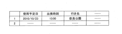
上記の電気自動車充電装置は、入力装置と、前記入力装置からの入力情報を記憶する記憶装置とを備え、前記記憶装置は、前記入力装置からの入力により指定された、前記高前記充電優先動作による充電動作の実行時間についての設定情報を記憶し、前記制御部は、前記充電優先動作による充電動作を前記設定情報が示す実行時間において実行する構成としてもよい。 The electric vehicle charging device includes an input device and a storage device that stores input information from the input device, and the storage device is designated by the input from the input device, the high charge priority operation The setting information about the execution time of the charging operation by the storage unit may be stored, and the control unit may execute the charging operation by the charge priority operation at the execution time indicated by the setting information.
上記の構成によれば、充電優先動作による充電動作が記憶装置に記憶されている設定情報が示す実行時間において実行される。これにより、ユーザは、入力装置を操作して充電優先動作による充電動作の実行時間を設定することにより、例えば電気自動車を使用しない時間など、希望する時間だけ電気自動車充電装置により充電優先動作による蓄電池の充電を行わせることができる。 According to said structure, the charge operation by charge priority operation is performed in the execution time which the setting information memorize | stored in the memory | storage device shows. Thereby, the user operates the input device to set the execution time of the charging operation by the charge priority operation, for example, the storage battery by the charge priority operation by the electric vehicle charging device for a desired time, such as a time when the electric vehicle is not used. Can be charged.
上記の電気自動車充電装置は、入力装置と、前記入力装置からの入力情報を記憶する記憶装置とを備え、前記記憶装置は、前記入力装置からの入力により指定された、前記高速充電モードの充電動作による前記蓄電池の満充電に対する充電量の上限値情報を記憶し、前記制御部は、前記電気自動車から、前記蓄電池の充電により変化する残電力量を示す情報を取得し、前記蓄電池の残電力量が前記上限値情報にて示される値に到達した場合に、前記充電優先動作による充電動作を終了させる構成としてもよい。 The electric vehicle charging apparatus includes an input device and a storage device that stores input information from the input device, and the storage device is charged in the fast charging mode specified by an input from the input device. The upper limit value information of the charge amount with respect to the full charge of the storage battery by operation is stored, and the control unit obtains information indicating the remaining power amount that changes due to the charge of the storage battery from the electric vehicle, and the remaining power of the storage battery When the amount reaches the value indicated by the upper limit value information, the charging operation by the charge priority operation may be terminated.
上記の構成によれば、制御部は、電気自動車から、蓄電池の充電により変化する残電力量を示す情報を取得し、蓄電池の残電力量が記憶装置に記憶されている上限値情報にて示される値に到達した場合に、充電優先動作による充電動作を終了させるように制御する。 According to said structure, a control part acquires the information which shows the remaining power amount which changes with charge of a storage battery from an electric vehicle, and shows the remaining power amount of a storage battery in the upper limit value information memorize | stored in the memory | storage device. When the value reaches the value, the charging operation by the charging priority operation is controlled to end.
したがって、ユーザは、入力装置を操作して、蓄電池の満充電に対する充電量の上限値を設定することにより、蓄電池の残電力量が希望する量となるように、電気自動車充電装置にて蓄電池を充電させることができる。 Therefore, the user operates the input device to set the upper limit value of the charge amount with respect to the full charge of the storage battery, so that the remaining power amount of the storage battery becomes a desired amount. It can be charged.
上記の電気自動車充電装置において、前記制御部は、前記充電器による前記電気自動車の蓄電池に対しての前記充電優先動作による充電動作の場合に、前記蓄電池の残電力量を示す情報を前記蓄電池を備えた電気自動車から取得するとともに、前記蓄電池を備えた電気自動車の予定走行距離、電力消費率および充電時間を示す各情報を取得し、取得したこれら情報に基づいて、前記充電時間あたりに必要な前記電気自動車の充電量を計算し、こ
の充電量を確保できるように、前記住宅設置電気機器への供給電力量を設定する構成としてもよい。
In the above-described electric vehicle charging device, the control unit uses the charger to store information indicating a remaining power amount of the storage battery in the case of a charging operation by the charging priority operation for the storage battery of the electric vehicle. Acquired from the equipped electric vehicle and each information indicating the planned travel distance, power consumption rate and charging time of the electric vehicle equipped with the storage battery, and based on the acquired information, required per charging time It is good also as a structure which calculates the charge amount of the said electric vehicle, and sets the electric power supply amount to the said house installation electrical equipment so that this charge amount can be ensured.
上記の構成によれば、制御部は、充電器による電気自動車の蓄電池に対しての前記充電優先動作による充電動作の場合、例えば高速充電モードによる充電動作の場合に、蓄電池の残電力量を示す情報を電気自動車から取得するとともに、電気自動車の予定走行距離、電力消費率および充電時間を示す各情報を取得する。そして、取得したこれら情報に基づいて、充電時間あたりに必要な電気自動車の充電量を計算し、この充電量を確保できるように、住宅設置電気機器への供給電力を設定する。したがって、住宅設置電気機器への供給電力は、設定された値になるように制御される。 According to said structure, a control part shows the remaining electric energy of a storage battery in the case of the charging operation by the said charge priority operation | movement with respect to the storage battery of the electric vehicle by a charger, for example, in the case of the charging operation by a high-speed charge mode, for example. While acquiring information from an electric vehicle, each information which shows the planned driving distance of an electric vehicle, a power consumption rate, and charging time is acquired. And based on these acquired information, the charge amount of the electric vehicle required per charge time is calculated, and the supply electric power to a house installation electrical device is set so that this charge amount can be ensured. Therefore, the power supplied to the house-installed electrical equipment is controlled to be a set value.
これにより、充電優先動作において、電気自動車への充電電力として、電気自動車が予定走行距離を走行するのに必要な分の電力を確保することができる。また、住宅設置電気機器への供給電力については、不要に削減される事態を防止することができる。 Thereby, in the charge priority operation, it is possible to secure the power necessary for the electric vehicle to travel the planned travel distance as the charging power for the electric vehicle. Moreover, about the power supplied to the electrical equipment installed in a house, it is possible to prevent an unnecessary reduction.
上記の電気自動車充電装置において、前記蓄電池を備えた電気自動車の予定走行距離、電力消費率および充電時間を示す各情報は、前記入力装置から入力される構成としてもよい。 In the above-described electric vehicle charging device, each piece of information indicating the planned travel distance, power consumption rate, and charging time of the electric vehicle including the storage battery may be input from the input device.
上記の構成によれば、電気自動車の予定走行距離、電力消費率および充電時間を示す各情報は、ユーザの操作により入力装置から入力することができるので、電気自動車充電装置は、簡単な構成にて、電気自動車が予定走行距離を走行するのに必要な分の電力を確保するための、住宅設置電気機器への供給電力量を設定することができる。 According to the above configuration, each information indicating the planned travel distance, power consumption rate, and charging time of the electric vehicle can be input from the input device by the user's operation. Therefore, the electric vehicle charging device has a simple configuration. Thus, it is possible to set the amount of electric power supplied to the electrical equipment installed in the house in order to secure the amount of power necessary for the electric vehicle to travel the planned travel distance.
上記の電気自動車充電装置は、前記住宅設置電気機器と前記受電設備に接続されたコンセントとの少なくとも一方に設けられた、前記充電優先動作による充電動作状態であることを報知する報知手段を備え、前記制御部は、前記充電優先動作による充電動作時に、前記報知手段を動作させる構成としてもよい。 The electric vehicle charging device includes a notifying unit that is provided in at least one of the house-installed electric device and the outlet connected to the power receiving facility, and that notifies the charging operation state by the charge priority operation, The said control part is good also as a structure which operates the said alerting | reporting means at the time of the charge operation by the said charge priority operation | movement.
上記の構成によれば、充電優先動作による充電動作状態であることが、住宅設置電気機器と受電設備に接続されたコンセントとの少なくとも一方に設けられたを報知手段によって報知されるので、ユーザは、充電優先動作による充電動作状態であることを容易に知ることができる。 According to said structure, since it is alert | reported by an alerting | reporting means that the charging operation state by charge priority operation | movement was provided in at least one of the electrical equipment installed in a house, and the outlet connected to the power receiving equipment, Thus, it is possible to easily know that the charging operation state is based on the charging priority operation.
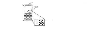
上記の電気自動車充電装置は、前記住宅設置電気機器と前記受電設備に接続されたコンセントとの少なくとも一方に設けられた、前記充電優先動作による充電動作に関する時間表示を行う時間表示手段を備え、前記制御部は、前記充電優先動作において、前記時間表示手段を動作させる構成としてもよい。 The electric vehicle charging device includes a time display unit that is provided in at least one of the house-installed electric device and an outlet connected to the power receiving facility, and displays a time related to a charging operation by the charging priority operation, The control unit may be configured to operate the time display means in the charge priority operation.
上記の構成によれば、住宅設置電気機器と受電設備に接続されたコンセントとの少なくとも一方に設けられた時間表示手段により、例えば充電優先動作による充電動作時間や、充電動作の開始時刻あるいは終了時刻などの、充電優先動作による充電動作に関する時間表示が行われる。したがって、ユーザは、時間表示手段により充電優先動作による充電動作に関する時間を容易に知ることができる。 According to the above configuration, the time display means provided in at least one of the home-installed electrical equipment and the outlet connected to the power receiving facility, for example, the charging operation time by the charge priority operation, the start time or the end time of the charging operation The time display regarding the charging operation by the charging priority operation is performed. Therefore, the user can easily know the time related to the charging operation by the charge priority operation by the time display means.
上記の電気自動車充電装置は、前記配線遮断器に設けられた、前記充電優先動作による充電動作状態であることを報知する報知手段を備え、前記制御部は、前記充電優先動作による充電動作時に、前記報知手段を動作させる構成としてもよい。 The electric vehicle charging apparatus includes a notification unit that is provided in the wiring breaker and notifies the charging operation state by the charge priority operation, and the control unit is in a charge operation by the charge priority operation, The notification unit may be operated.
上記の構成によれば、充電優先動作による充電動作状態であることが、配線遮断器に設
けられた報知手段によって報知されるので、ユーザは、充電優先動作による充電動作状態であることを容易に知ることができる。
According to said structure, since it is alert | reported by the alerting | reporting means provided in the wiring breaker that it is the charge operation state by charge priority operation | movement, a user can easily be the charge operation state by charge priority operation | movement. I can know.
上記の電気自動車充電装置は、前記配線遮断器に設けられた、前記充電優先動作による充電動作に関する時間表示を行う時間表示手段を備え、前記制御部は、前記充電優先動作において、前記時間表示手段を動作させる構成としてもよい。 The electric vehicle charging apparatus includes a time display unit that is provided in the wiring breaker and displays time related to a charging operation by the charging priority operation, and the control unit includes the time display unit in the charging priority operation. It is good also as a structure which operates.
上記の構成によれば、配線遮断器に設けられた時間表示手段により、例えば充電優先動作による充電動作時間や、充電動作の開始時刻あるいは終了時刻などの、充電優先動作による充電動作に関する時間表示が行われる。したがって、ユーザは、時間表示手段により充電優先動作による充電動作に関する時間を容易に知ることができる。 According to the above configuration, the time display means provided in the circuit breaker can display the time related to the charging operation by the charge priority operation, such as the charging operation time by the charge priority operation, the start time or the end time of the charging operation, for example. Done. Therefore, the user can easily know the time related to the charging operation by the charge priority operation by the time display means.
上記の電気自動車充電装置において、前記住宅設置電気機器が接続されるコンセントには、コンセントからの給電を遮断する遮断回路が設けられ、前記制御部は、前記高速充電モードにおいて、前記住宅設置電気機器が接続されていないコンセントの前記遮断回路を遮断させる構成としてもよい。 In the electric vehicle charging apparatus, the outlet to which the house-installed electric device is connected is provided with a cut-off circuit that cuts off power supply from the outlet, and the control unit is configured to operate the house-installed electric device in the high-speed charge mode. It is good also as a structure which interrupts | blocks the said interruption | blocking circuit of the electrical outlet which is not connected.
上記の構成によれば、高速充電モードにおいて、住宅設置電気機器が接続されていないコンセントの遮断回路が遮断される。これにより、高速充電モードにおいて、空いているコンセントに新たに住宅設置電気機器が接続されてコンセントから給電が行われてしまい、住宅設置電気機器の消費電力が増加する事態を防止すること、すなわち電気自動車への充電電力が減少する事態を防止することができる。 According to said structure, in the high-speed charge mode, the interruption | blocking circuit of the electrical outlet which is not connected to the house installation electrical equipment is interrupted | blocked. As a result, in the high-speed charging mode, it is possible to prevent a situation where a newly installed electrical device is connected to a vacant outlet and power is supplied from the outlet, resulting in an increase in power consumption of the residential electrical device. It is possible to prevent a situation where the charging power to the automobile is reduced.
上記の電気自動車充電装置において、前記住宅設置電気機器が接続されるコンセントと接続されている配線遮断器には、前記コンセントへの給電を遮断する遮断回路が設けられ、前記制御部は、前記高速充電モードにおいて、前記住宅設置電気機器が接続されていないコンセントのみに接続されている前記配線遮断器の前記遮断回路を遮断させる構成としてもよい。 In the electric vehicle charging apparatus, the wiring breaker connected to the outlet to which the house-installed electrical device is connected is provided with a cutoff circuit that cuts off power supply to the outlet, and the control unit In the charging mode, the circuit breaker of the wiring breaker connected only to an outlet not connected to the house-installed electrical equipment may be blocked.
上記の構成によれば、高速充電モードにおいて、住宅設置電気機器が接続されていないコンセントのみに接続されている配線遮断器の遮断回路が遮断される。これにより、高速充電モードにおいて、空いているコンセントに新たに住宅設置電気機器が接続されてコンセントから給電が行われてしまい、住宅設置電気機器の消費電力が増加する事態を防止すること、すなわち電気自動車への充電電力が減少する事態を防止することができる。 According to said structure, the interruption | blocking circuit of the wiring breaker connected only to the electrical outlet which is not connected to a house installation electrical apparatus is interrupted | blocked in high-speed charge mode. As a result, in the high-speed charging mode, it is possible to prevent a situation where a newly installed electrical device is connected to a vacant outlet and power is supplied from the outlet, resulting in an increase in power consumption of the residential electrical device. It is possible to prevent a situation where the charging power to the automobile is reduced.
本発明の構成によれば、高速充電モードによる充電動作の場合に、低速充電モードによる充電動作の場合よりも、住宅設置電気機器への供給電力が削減され、電気自動車への充電電力が増加するように、住宅設置電気機器への供給電力が制御される。これにより、使用電力上限値が設定されている条件下において、高速充電モードによる蓄電池に対しての充電を適切に行うことができる。 According to the configuration of the present invention, in the charging operation in the high-speed charging mode, the power supplied to the house-installed electrical device is reduced and the charging power to the electric vehicle is increased compared to the charging operation in the low-speed charging mode. As described above, the power supplied to the electrical equipment installed in the house is controlled. Thereby, the charge with respect to the storage battery by high-speed charge mode can be performed appropriately on the conditions in which the electric power use upper limit is set.
〔実施の形態1〕
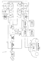
本発明の実施の形態を図面に基づいて以下に説明する。図1は、住宅の受電設備1に電気自動車充電装置2が備えられている状態を示す説明図である。
[Embodiment 1]
Embodiments of the present invention will be described below with reference to the drawings. FIG. 1 is an explanatory diagram illustrating a state where an electric
図1に示すように、受電設備1は、電力メーター11および分電盤12を備えている。電力会社からの交流電力13は、電力メーター11を介して分電盤12に供給される。
As shown in FIG. 1, the
分電盤12は、第1配線遮断器21、漏電遮断器22、複数の第2配線遮断器23、お
よび第3配線遮断器24を備えている。
The
第1配線遮断器21は、受電側に設けられる大本の配線遮断器であり、定格が大電流のものである。一方、第2配線遮断器23および第3配線遮断器24は、定格が小電流のものであり、第2配線遮断器23には住宅に備えられた電気機器、すなわち住宅設置電気機器が接続され、第3配線遮断器24には充放電器53が接続される。
The
図1の例では、第2配線遮断器23毎に、洗濯乾燥機31、照明32、エアーコンディショナー(以下、単にエアコンと称する)33、オーディオ機器34、パーソナルコンピュータ(以下、単にパソコンと称する)35、およびテレビジョン受像機(以下、単にテレビと称する)36が接続されている。
In the example of FIG. 1, for each
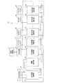
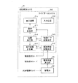
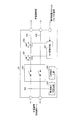
分電盤12は、具体的には、図2に示す構成となっている。図2は分電盤12の具体的な構成を示す説明図である。分電盤12には、受電側から順番に、第1配線遮断器21、漏電遮断器22、第3配線遮断器24、および複数の第2配線遮断器23が並ぶように配置されている。第1配線遮断器21には、L1線、N線(中性線)およびL2線からなる給電線41により200Vの交流電力が入力されている。給電線41は、さらに漏電遮断器22を介して、複数の第2配線遮断器23の並び方向に伸びている。
Specifically, the
第3配線遮断器24は、上記のように充放電器53と接続され、複数の第2配線遮断器23は、200Vコンセント42もしくは100Vコンセント43と接続されている。
The
充放電器53に接続されている第3配線遮断器24、および200Vコンセント42に接続されている第2配線遮断器23は、給電線41のL1線およびL2線と接続されることにより、200Vが入力されている。100Vコンセント43に接続されている第2配線遮断器23は、給電線41のL1線およびN線またはL2線およびN線と接続されることにより、100Vが入力されている。
The
電気自動車充電装置2は、図1に示すように、Ph電力モニター51、Pv電力モニター52、充放電器53、制御装置54、表示装置55および入力装置56を備えている。
As shown in FIG. 1, the electric
Ph電力モニター51は、住宅設置電気機器に供給されている電力量の総量を検出するように、給電線41に配置されている。Pv電力モニター52は、充放電器53に供給される電力量を検出するように、充放電器53に接続されている第3配線遮断器24と給電線41との間に設けられている。
The Ph power monitor 51 is disposed on the
充放電器53は、電気自動車3の蓄電池62の充電の場合に、給電線41からの交流電力を直流電力に変換して電気自動車3に供給する。このために、充放電器53は交流を直流電力に変換するAC−DCインバータと充電電流(充電電力)を制御するDC−DCコンバータ(図示せず)を備えている。また、充放電器53は、電気自動車3の蓄電池62から住宅の受電設備1への放電の場合に、住宅設置電気機器、具体的には住宅に設置された家庭用据え置き蓄電池(図示せず)に電力を供給し、充電させる。このために、充放電器53は、DC−DCコンバータ(図示せず)を備えている。また、充放電器53は、DC−DCコンバータとAC−DCインバータ(図示せず)を備えており、電気自動車3の蓄電池62の直流電力をDC−DCコンバータにより商用交流系統へ逆潮流可能な電圧に調整する。さらに、AC−DCインバータにより交流電力に変換して商用交流系統へ供給することで、住宅設置電気機器(家電機器)へ供給する。
DC−DCコンバータとAC−DCインバータは双方向に出力可能な構成、制御にすることが好ましい。当然、充電用、放電用とそれぞれDC−DCコンバータとAC−DCインバータを備えてもよい。また、家庭用据え置き蓄電池には双方向のAC−DCインバータ
と双方向のDC−DCコンバータを備え、商用電力系統から充電し、充電電力を商用電力系統へ連携し、逆潮流させることが可能とする。
When charging the
It is preferable that the DC-DC converter and the AC-DC inverter have a configuration and control capable of bidirectional output. Naturally, a DC-DC converter and an AC-DC inverter may be provided for charging and discharging, respectively. In addition, a home-use stationary storage battery is equipped with a bidirectional AC-DC inverter and a bidirectional DC-DC converter, and can be charged from the commercial power system, and the charged power can be linked to the commercial power system and flow backward. To do.
また、充放電器53は、蓄電池62を充電する場合において、低速充電モードによる充電と高速充電モードによる充電(充電優先動作による充電)とのいずれか一方を選択できるようになっている。低速充電モードは、高速充電モードよりも、少ない供給電力により長時間かけて蓄電池62を充電するものである。一方、高速充電モードは、低速充電モードよりも、多い供給電力により短時間にて蓄電池62を充電するものである。
Further, when charging the
高速充電モードと低速充電モードとの切り替えは、例えばユーザが入力装置56を操作して高速充電モードもしくは低速充電モードを指定するようにしてもよい。このユーザ操作により、表示装置55には指定されたモードが表示される。この場合、充放電器53には電圧200Vの電力の入力を受けて、低速充電モードであれば低速充電用の低電力の直流電圧を出力し、高速充電モードであれば高速充電用の高電力の直流電圧を出力する構成であってもよい。あるいは、充放電器53は、入力用のプラグが200Vコンセント42に接続された場合に高速充電モードとなり、100Vコンセント43に接続された場合に低速充電モードとなる構成であってもよい。
The switching between the fast charge mode and the slow charge mode may be performed, for example, by the user operating the
さらに、充放電器53は、出力電力を複数段階に切り替え可能となっている。具体的には、低速充電モードと高速充電モードとに応じて出力電力の切り替えが可能であり、また、高速充電モードにおいても複数段階の出力電力の切り替えが可能である。
Furthermore, the charger /
制御装置54は、充放電器53による電気自動車3の蓄電池62に対しての充電動作、および電気自動車3の蓄電池62の放電による住宅設置の蓄電池に対する充電動作など、充放電器53の動作を制御する。また、制御装置54は、住宅に契約電力(使用電力上限値)が設定されている状態において、高速充電モードが選択されている場合に、高速充電モードによる蓄電池62の充電が適切に行われるように、住宅設置電気機器への供給電力Phを制御する。
The
すなわち、電気自動車への充電電力Pvの実測値をPv1(Pv電力モニター52の測定値)とし、住宅設置電気機器への供給電力Phの実測値をPh1(Ph電力モニター51)とした場合、分電盤12への入力電力Pinは、
Pin=Ph1+Pv1
となる。また、電気自動車充電装置2を備えた住宅において、契約電力Pcが設定されている場合、分電盤12への入力電力Pinが契約電力Pcを超えると、第1配線遮断器21が遮断され、電力が供給されなくなる。または、契約電力を超えることによって、料金体系が変化し、電気料金が高くなる。したがって、
Pc>Pin
とする必要がある。すなわち、分電盤12への入力電力Pinの上限値は、契約電力Pcよりも小さい所定値に設定される。
That is, when the measured value of the charging power Pv to the electric vehicle is Pv1 (measured value of the Pv power monitor 52) and the measured value of the supplied power Ph to the house-installed electrical equipment is Ph1 (Ph power monitor 51), The input power Pin to the
Pin = Ph1 + Pv1
It becomes. Moreover, in the house provided with the electric
Pc> Pin
It is necessary to. That is, the upper limit value of the input power Pin to the
そこで、制御装置54は、高速充電モードが設定されると、住宅設置電気機器への供給電力Phが減少するように制御する。これにより、Pc>Pinという条件の下であっても、高速充電モードによる蓄電池62の充電が可能となる。
Therefore, when the high-speed charging mode is set, the
次に、上記の動作を行う電気自動車充電装置2の構成について詳細に説明する。図3は、図1に示した電気自動車充電装置2を備えた電気自動車充電システムの構成を示すブロック図である。
Next, the configuration of the electric
図3に示すように、制御装置54は、制御部71、記憶装置72および通信部73を備
えている。通信部73は、住宅設置電気機器群82との間で、制御信号等の送受信を行うリモートコントローラ(以下、単にリモコンと称する)であってもよい。
As shown in FIG. 3, the
制御装置54には、表示装置55、入力装置56、Ph電力モニター51、Pv電力モニター52、第2配線遮断器群81、住宅設置電気機器群82、コンセント群83および充放電器53が接続されている。充放電器53には、電気自動車3の蓄電池62を充電する際に、電気自動車3に搭載されている電気自動車システム61が接続される。
Connected to the
第2配線遮断器群81は、図1に示した複数の第2配線遮断器23の各々を示す。第2配線遮断器群81に含まれる各第2配線遮断器23は、制御部101、遮断駆動装置102および表示装置103を備えている。遮断駆動装置102は、第2配線遮断器23を遮断させる動作を行うものである。遮断駆動装置102は、第2配線遮断器23を流れる電流値が規定値を超えた場合の通常の遮断動作に加えて、制御部101の制御による遮断動作を行う。
The second
住宅設置電気機器群82は、図1に示した複数の第2配線遮断器23に接続されている洗濯乾燥機31、照明32、エアコン33、オーディオ機器34、パソコン35、およびテレビ36等の各々を示す。各住宅設置電気機器は、通信部91、制御部92、記憶装置93および表示装置94を備えている。
The house-installed
コンセント群83は、図2に示した複数の200Vコンセント42および100Vコンセント43の各々を示す。コンセント群83に含まれる各コンセントは、制御部111および表示装置112を備えている。
The
電気自動車システム61は、電気自動車3に搭載されており、蓄電池62および電池残量測定部63を備えている。この電池残量測定部63は、蓄電池62の残電力量を測定する。
The
入力装置56からは電気自動車充電装置2に対する種々の設定のためのユーザ入力が行われる。制御装置54の制御部71は入力装置56により行われた設定を記憶装置72に記憶させるとともに、表示装置55に表示させる。
User input for various settings for the electric
(電力削減設定)
具体的には、入力装置56に対するユーザの操作により、高速充電モードが設定された場合には、分電盤12への入力電力Pinについての、住宅設置電気機器への供給電力Phと電気自動車への充電電力Pvとへの振分け設定が行われる。
(Power reduction setting)
Specifically, when the high-speed charging mode is set by a user operation on the
以下では、供給電力Phへの振分け電力をPhset1とし、充電電力Pvへの振分け電力を充電電力Pvset1として示す。供給電力Phset1が設定された場合、住宅設置電気機器は、供給電力Phset1を許容上限値として入力電力Pinを使用できる。一方、充電電力Pvset1が設定された場合、充放電器53は、制御部71によって出力電力が切り替えられ、供給される充電電力Pvset1に応じた電力を出力する。
Hereinafter, the distribution power to the supplied power Ph is denoted as Phset1, and the distribution power to the charging power Pv is denoted as charging power Pvset1. When the supply power Phset1 is set, the house-installed electrical device can use the input power Pin with the supply power Phset1 as the allowable upper limit value. On the other hand, when the charging power Pvset1 is set, the charger /
また、上記の振分け設定を実行するために、住宅設置電気機器群82に含まれる各住宅設置電気機器に対しては、消費電力の削減設定が行われる。この設定内容は、記憶装置72に記憶される。
In addition, in order to execute the above-described distribution setting, power consumption reduction setting is performed for each house-installed electric device included in the house-installed
例えば、契約電力Pcから見て許容される分電盤12への入力電力Pinの最大値が10kWである場合、高速充電モード以外の状態では、入力電力Pinの10kWを住宅設置電気機器への供給電力Phに7kWが振り分けられ、電気自動車への充電電力Pvに3
kWが振り分けられる。
For example, when the maximum value of the input power Pin to the
kW is distributed.
これに対し、高速充電モードでは、ユーザの設定に応じて住宅設置電気機器への供給電力Phを削減し、住宅設置電気機器への供給電力Ph(供給電力Phset1)として5kWが振り分け振られ、電気自動車への充電電力Pv(充電電力Pvset1)として5kWが振り分けられる。このような高速充電モードでの入力電力Pinについての供給電力Phおよび充電電力Pvへの配分は、予めユーザが入力装置56を操作して設定しておくことができる。
In contrast, in the fast charge mode, the supply power Ph to the house-installed electrical device is reduced according to the user's setting, and 5 kW is distributed as the power supply Ph (supply power Phset1) to the house-installed electrical device. 5 kW is allocated as the charging power Pv (charging power Pvset1) for the automobile. The distribution of the input power Pin in the high-speed charging mode to the supplied power Ph and the charging power Pv can be set in advance by the user operating the
なお、高速充電モード以外の状態における住宅設置電気機器への供給電力Phおよび電気自動車への充電電力Pvへの振り分けは必須ではなく、高速充電モードにおいて、設定した充電電力Pv(充電電力Pvset1)が確保されるように住宅設置電気機器への供給電力Phが削減され、その分が電気自動車への充電電力Pvに振り分けられる構成であればよい。 It is not essential to distribute the supply power Ph to the home-installed electrical equipment and the charge power Pv to the electric vehicle in a state other than the fast charge mode, and the set charge power Pv (charge power Pvset1) is set in the fast charge mode. Any configuration may be employed as long as the power supply Ph supplied to the home-installed electrical equipment is reduced so as to be secured, and that amount is distributed to the charge power Pv supplied to the electric vehicle.
また、住宅設置電気機器に対し、削減対象外として使用する機器や、住宅設置電気機器に最低限消費する電力を設定することができる。この場合、高速充電モードにおいても、契約電力から電気機器の削減不可能な電力を除いた電力の中で充電電力を設定することができる。高速充電モードにおいて、新たに機器の起動や、機器の消費電力をアップさせるような設定ができないように、コンセント部およびブレーカ部および家電機器で制御される。 In addition, it is possible to set a device to be used as an out-of-reduction target or a power consumed at a minimum for the home-installed electrical device for the home-installed electrical device. In this case, even in the high-speed charging mode, the charging power can be set in the power obtained by subtracting the power that cannot be reduced from the contract power. In the high-speed charging mode, control is performed by the outlet unit, the breaker unit, and the home electric appliance so that the device cannot be activated or set to increase the power consumption of the device.
(電力削減内容)
高速充電モードにおいて、住宅設置電気機器への供給電力Phを削減する場合には、各住宅設置電気機器に対して一律に所定%を削減するように設定されてもよい。一律削減は削減が可能な家電機器に限られ、例えば、エアコンの温度設定とテレビの明るさ、LED照明の輝度、IHの出力などが一律に概略10%や20%削減される。あるいは、一部の住宅設置電気機器のみへの供給電力を削減するように設定してもよい。例えば、図1に示した住宅設置電気機器では、電力削減対象電気機器を照明32、エアコン33、オーディオ機器34およびテレビ36とすることができる。この場合、通常時の設定に対して、照明32については暗くする、エアコン33については冷房温度を上げるあるいは暖房温度を下げる、オーディオ機器34については音量を低下させる、テレビ36については輝度および音量を低下させるなどである。
(Content of power reduction)
In the high-speed charging mode, when reducing the electric power Ph supplied to the house-installed electric device, the predetermined electric power may be set to be uniformly reduced for each house-installed electric device. The uniform reduction is limited to household appliances that can be reduced. For example, the temperature setting of the air conditioner, the brightness of the television, the brightness of the LED illumination, the output of the IH, etc. are uniformly reduced by approximately 10% or 20%. Or you may set so that the electric power supplied only to some housing installation electrical equipment may be reduced. For example, in the house-installed electric device shown in FIG. 1, the electric appliances targeted for power reduction can be the
この場合、制御部71は、ユーザにて操作される入力装置56からの要求に応じて、電力削減対象電気機器およびその電力削減内容を設定するためのユーザインターフェースを表示装置55に表示させ、ユーザに設定の入力を促すようにしてもよい。
In this case, in response to a request from the
上記のように、ユーザの入力装置56に対する操作により、電力削減対象電気機器および電力削減内容が設定されると、制御装置54の制御部71は、その設定内容を電力削減内容情報として記憶装置72に記憶させる。また、制御部71は、通信部73から住宅設置電気機器群82における電力削減対象電気機器に対して、電力削減内容情報を送信する。
As described above, when the power reduction target electrical device and the power reduction content are set by the user's operation on the
電力削減対象電気機器では、通信部73から電力削減内容情報が送信されてくると、その電力削減内容情報を通信部91にて受信する。また、電力削減対象電気機器の制御部92は、通信部91が受信した電力削減内容情報を記憶装置93に記憶させる。なお、通信部73と通信部91との通信は、無線通信あるいは有線による通信のいずれであってもよい。
In the power reduction target electrical device, when the power reduction content information is transmitted from the
上記のようにして、電力削減内容情報が電力削減対象電気機器に取り込まれた状態において、電気自動車充電装置2は、電気自動車3に対する高速充電モードによる充電の指示を受けると、制御装置54が高速充電モードにより電気自動車3の充電を開始する旨を通信部73から住宅設置電気機器群82の電力削減対象電気機器に送信する。電力削減対象電気機器では、通信部91によりその情報を受信すると、制御部92が記憶装置93から電力削減内容情報を読み出し、電力削減内容情報が示す電力削減内容にしたがって、消費電力が削減されるように、電力削減対象電気機器の動作を制御する。
As described above, when the electric
また、高速充電モード時において、新たに電気機器をコンセントに挿して動作させることがないように、第2配線遮断器23(ブレーカ)もしくはコンセントに遮断スイッチを備え、その遮断スイッチをOFFさせることで、家庭内の電気機器の消費電力を増加させることを防ぐようにしてもよい。この場合に遮断スイッチをOFFさせる制御の対象となるのは、家庭内消費電力の余力に対し、電力を供給可能で、ユーザが設定した優先順位の高いものを残したコンセント以外のコンセント、あるいは第2配線遮断器23である。
Also, in the fast charge mode, the second wiring breaker 23 (breaker) or the outlet is provided with a cutoff switch so that a new electrical device is not inserted into the outlet and operated, and the cutoff switch is turned off. Further, it may be possible to prevent an increase in power consumption of electrical equipment in the home. In this case, the target of the control for turning off the cutoff switch is the outlet other than the outlet that can supply power with respect to the remaining power consumption in the home and that has the high priority set by the user, or the first outlet. This is a two-
なお、第2配線遮断器23に遮断スイッチ(第1FET302、第2FET303)を設けた構成については、図19に基づいて後述する。
In addition, the structure which provided the interruption | blocking switch (1st FET302, 2ndFET303) in the
この場合、例えば、各第2配線遮断器23の電力容量が1.5kWであり、家庭内の電気機器において消費可能な電力が1.5kW以下であれば、電力供給を行っていない第2配線遮断器23もしくはコンセントに備えた上記遮断スイッチをOFFさせるようにしてもよい。また、例えば、電気自動車への充電電力設定が5kWである場合に、家庭内の電気機器にて1.5kWしか電力消費していなかったとき、1.5kW容量の第2配線遮断器23の2つを使用可能状態とし、その他の第2配線遮断器23の遮断スイッチはOFFさせるようにしてもよい。この場合、各ブレーカおよび各コンセントのどれを使用可能にするかという優先順位は、ユーザが設定可能とする。また、コンセントおよびブレーカには、遮断若しくは制限により、使用できないことを示すために表示機能を備えることが好ましい(図4および図5参照)。
In this case, for example, if the power capacity of each
(充電電力Pvの追加)
次に、高速充電モードにおいて、ユーザの操作により入力装置56から電気自動車への充電電力Pvに対する追加要求が入力された場合に対応する電気自動車充電装置2の構成について説明する。
(Addition of charging power Pv)
Next, the configuration of the electric
電気自動車への充電電力Pvの追加要求は、ユーザがさらに充電時間の短縮を希望する場合に、入力装置56を操作して入力される。充電電力Pvの追加要求の入力は、高速充電モードを選択した後、かつ電気自動車3への充電が開始される前の時点、あるいは高速充電モードによる充電を行っている途中の時点のいずれの時点に行われてもよい。
The request for adding the charging power Pv to the electric vehicle is input by operating the
充電電力Pvの追加要求が入力された場合の充電電力Pvの追加後の値、すなわち入力電力Pin10kWの振り分けは、例えば、住宅設置電気機器への供給電力Phset2としてに3kW、電気自動車への充電電力Pvset2として7kWとなる。この振り分けの設定の入力は、充電電力Pvの追加要求が入力される前の時点、あるいは充電電力Pvの追加要求が入力された後の時点のいずれの時点に行われてもよい。入力装置56から上記振分け設定が入力されると、制御部71はその設定内容を記憶装置72に記憶させる。
The value after the addition of the charging power Pv when the request for adding the charging power Pv is input, that is, the distribution of the
(追加の電力削減内容)
制御装置54の制御部71は、充電電力Pvの追加要求が入力された場合において、その時点における住宅設置電気機器への供給電力Ph1が、充電電力Pvの追加要求が行わ
れた場合の住宅設置電気機器への供給電力Phset2を超える場合に、住宅設置電気機器群82に対して電力追加削減要求を行う。この電力追加削減要求は、住宅設置電気機器群82の消費電力のさらなる低下を指示するものである。
(Additional power reduction content)
When a request for adding charging power Pv is input, the
なお、充電電力Pvの追加要求は、充電電力Pvset1を充電電力Pvset2に増加するという要求である。また、供給電力Ph1が、充電電力Pvの追加要求が行われた場合の住宅設置電気機器への供給電力Phset2を超える場合とは、供給電力Ph1を削減せずに、充電電力Pvset2を設定すると入力電力Pinが上限値を超える場合である。 The request for adding the charging power Pv is a request for increasing the charging power Pvset1 to the charging power Pvset2. In addition, when the supply power Ph1 exceeds the supply power Phset2 to the home-installed electrical equipment when the request for adding the charge power Pv is made, it is input when the charge power Pvset2 is set without reducing the supply power Ph1. This is a case where the power Pin exceeds the upper limit value.
高速充電モードでの電力追加削減要求に応じて、住宅設置電気機器への供給電力Phを削減する場合には、最初に高速充電モードが設定された場合と同様、各住宅設置電気機器に対してさらに一律に所定%を削減するように設定されてもよい。あるいは、住宅設置電気機器群82の各住宅設置電気機器に対して、電力追加削減対象電気機器としての優先順位を設定し、優先順位の高いものから順次供給電力を削減するように設定してもよい。なお、住宅設置電気機器の消費電力を一律に削減する場合の所定%の消費電力の削減量は、高速充電モードにおける住宅設置電気機器への供給電力Phset1とさらなる電力追加削減要求に応じた場合の住宅設置電気機器への供給電力Phset2との差に相当するものである。
In response to a request for additional power reduction in the high-speed charging mode, when reducing the power supply Ph to the home-installed electric equipment, as in the case where the fast-charge mode is initially set, Further, it may be set so as to reduce the predetermined percentage uniformly. Alternatively, it is possible to set the priority order of the electric appliances subject to additional power reduction for each electric appliance installed in the household
例えば、図1に示した住宅設置電気機器において、電力削減対象電気機器として照明32、エアコン33、オーディオ機器34およびテレビ36が選定されている場合に、これらをさらに電力追加削減対象電気機器として選定する場合、一律に消費電力を所定%削減する電力追加削減では、それらの消費電力がさらに低下するような設定を行う。この場合の消費電力の低下は、電力追加削減対象電気機器の電源をオフにするものであってもよい。
For example, when the
また、ユーザの入力装置56からの入力により、電力追加削減対象電気機器としての優先順位が設定される場合、順位の高い順に、例えばエアコン33、オーディオ機器34、テレビ36、照明32が設定される。この場合の電力削減内容についても、電源をオフにする設定を含め、それらの消費電力をさらに低下させるものである。
Further, when the priority order as the electric power reduction target electric device is set by the input from the
電力追加削減に関する設定を行う場合、制御部71は、ユーザにて操作される入力装置56からの要求に応じて、電力追加削減対象電気機器およびその電力削減内容を設定するためのユーザインターフェースを表示装置55に表示させ、ユーザに設定の入力を促すようにしてもよい。
When performing settings related to additional power reduction, the
上記のように、ユーザの入力装置56に対する操作により、電力追加削減対象電気機器および電力追加削減内容が設定されると、制御装置54の制御部71は、その設定内容を電力追加削減内容情報として記憶装置72に記憶させる。
As described above, when the electric power addition reduction target electrical device and the power addition reduction content are set by the user's operation on the
電気自動車充電装置2は、高速充電モードが設定されている状態において、Ph電力モニター51およびPv電力モニター52により、住宅設置電気機器への供給電力Phおよび電気自動車への充電電力Pvを監視している。この状態において、制御装置54の制御部71は、電力追加削減要求が必要となった場合に、電力追加削減対象電気機器としての優先順位が設定されていなければ、電力追加削減対象電気機器に対して一律に所定%の消費電力の削減を指示する。
In the state where the high-speed charging mode is set, the electric
また、制御装置54の制御部71は、電力追加削減要求が必要となった場合に、電力追加削減対象電気機器としての優先順位が設定されていれば、優先順位第1位の電力追加削
減対象電気機器(住宅設置電気機器)についての電力追加削減内容情報を読み出す。そして、読み出した電力追加削減内容情報を優先順位第1位の電力追加削減対象電気機器に送信する。
In addition, when a power addition reduction request is required, the
電力追加削減内容情報を受信した電力追加削減対象電気機器では、受信した電力追加削減内容情報を記憶装置93に記憶させる。制御部92は、記憶装置93から電力追加削減内容情報を読み出し、電力追加削減内容情報が示す電力削減内容にしたがって、消費電力が削減されるように、電力追加削減対象電気機器の動作を制御する。これにより、住宅設置電気機器への供給電力Phは、優先順位第1位の電力追加削減対象電気機器について消費電力の削減分だけ削減され、その分、電気自動車への充電電力Pvを増加させることが可能になる。
The electric power addition reduction target electrical device that has received the electric power addition reduction content information stores the received electric power addition reduction content information in the
制御装置54の制御部71では、Ph電力モニター51が示す値から、優先順位第1位の電力追加削減対象電気機器についての消費電力の削減により、住宅設置電気機器への供給電力Ph1が電力追加削減要求の設定値(供給電力Phset2)に達したか(電気自動車への充電電力Pvの追加分を確保できたか)どうかを判断する。その結果、電力追加削減要求の設定値(供給電力Phset2)に達していなければ、同様にして、優先順位第2位の電力追加削減対象電気機器に対して、消費電力の削減を指示する。この処理は、住宅設置電気機器への供給電力Phが電力追加削減要求の設定値(供給電力Phset2)に達するまで、順次下位の優先順位の電力追加削減対象電気機器に対して繰り返していく。
In the
(高速充電モード状態の表示)
第2配線遮断器群81、住宅設置電気機器群82およびコンセント群83では、高速充電モードによる電気自動車3の充電中に、その旨をそれぞれの表示装置103、表示装置94および表示装置112に表示するようになっている。この場合の表示装置103、表示装置94および表示装置112は、高速充電モードによる電気自動車3の充電中に点灯される例えばLEDランプであってもよい。これにより、家電機器の消費電力が削減されていることや、電力が遮断されていること等がわかり、ユーザが機器の異常や配線の異常を心配することがなく、安心できる。
(Display of fast charge mode status)
In the second
図4は、図3に示した表示装置103としてのLEDランプ(報知手段)121を備えた第2配線遮断器23を示す正面図である。図5は、図3に示した表示装置112としてのLEDランプ121を備えた200Vコンセント42あるいは100Vコンセント43を示す正面図である。
FIG. 4 is a front view showing a
第2配線遮断器23のLEDランプ121の点灯は、高速充電モードによる電気自動車3の充電が行われている場合に、その旨が制御装置54の制御部71から第2配線遮断器群81の制御部101に伝えられ、制御部101によってLEDランプ121(表示装置103)が点灯される。同様に、200Vコンセント42あるいは100Vコンセント43のLEDランプ121の点灯は、高速充電モードによる電気自動車3の充電が行われている場合に、その旨が制御装置54の制御部71からコンセント群83の制御部111に伝えられ、制御部111によってLEDランプ121(表示装置112)が点灯される。なお、住宅設置電気機器群82に含まれる住宅設置電気機器が表示装置94としてのLEDランプ121を備えている場合については図示していない。しかしながら、各住宅設置電気機器に対しても同様にLEDランプ121を設け、そのLEDランプ121を同様にして制御することができる。
The
なお、ユーザに対する高速充電モード状態であることを報知は、LEDランプ121による表示に限らず、例えばスピーカからの報知音あるいは音声により行うものであっても
よい。
The notification that the user is in the fast charge mode state is not limited to the display by the
(高速充電の残時間表示)
また、第2配線遮断器群81、住宅設置電気機器群82およびコンセント群83では、高速充電モードによる電気自動車3の充電中に、それぞれの表示装置103、表示装置94および表示装置112に高速充電モードの残り時間を表示してもよい。この場合の表示装置103、表示装置94および表示装置112は、高速充電モードによる電気自動車3の充電中に高速充電モードの残り時間を時計表示するものとなる。
(Fast charge remaining time display)
Further, in the second
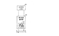
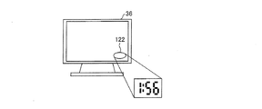
図6は、図3に示した表示装置103としての時間表示装置(時間表示手段)122を備えた第2配線遮断器23を示す正面図である。図7は、図3に示した表示装置94としての時間表示装置122を備えたテレビ36を示す説明図である。図8は、図3に示した表示装置94としての時間表示装置122を備えた電気自動車充電装置2のリモコン37を示す説明図である。図9は、図3に示した表示装置112としての時間表示装置122を備えた200Vコンセント42あるいは100Vコンセント43を示す説明図である。
FIG. 6 is a front view showing the
上記の各時間表示装置122において高速充電モードの残り時間を表示する場合に、制御装置54の制御部71は、高速充電モードの完了予測時間を計算し、第2配線遮断器群81、住宅設置電気機器群82およびコンセント群83に伝える。あるいは、制御部71は、高速充電モードの残り時間をカウントダウンしていき、カウントダウンごとに残り時間を第2配線遮断器群81、住宅設置電気機器群82およびコンセント群83に伝える。
When displaying the remaining time in the high-speed charging mode on each
制御部71から完了予測時間を受信した場合、第2配線遮断器群81、住宅設置電気機器群82およびコンセント群83の制御部101、制御部92および制御部111は、それらが備える時計機能により、完了予測時間をカウントダウンしていき、時間表示装置122に表示させる。あるいは制御部71からカウントダウンされていく高速充電モードの残り時間を受信した場合、第2配線遮断器群81、住宅設置電気機器群82およびコンセント群83の制御部101、制御部92および制御部111は、受信した残り時間を時間表示装置122に表示させる。なお、後者の場合、制御部71は、完了予測時間を常時計算し、更新していくようにしても良い。
When the predicted completion time is received from the
高速充電モードの完了予測時間を計算する場合、制御装置54の制御部71は、蓄電池62の残電力量情報、充電完了状態情報および電気自動車への充電電力Pv情報を取得し、これら情報に基づいて完了予測時間を計算する。各情報の取得に関し、制御装置54の制御部71は、蓄電池62の残電力量情報を電気自動車システム61の電池残量測定部63から取得する。充電完了状態情報は、高速充電モードによる蓄電池62の充電完了を満充電に対する80%あるいは60%とするなど、例えばユーザの入力装置56に対する操作により予め設定されているものであり、記憶装置72から取得する。また、電気自動車への充電電力Pv情報は、高速充電モードにおける電気自動車への充電電力Pv情報として予め設定されているものであり、記憶装置72から取得する。
When calculating the predicted completion time of the fast charging mode, the
なお、ユーザに対する高速充電モードの残り時間の報知は、時間表示装置122による表示に限らず、例えばスピーカからの報知音あるいは音声によって行うものであってもよい。
The notification of the remaining time in the high-speed charging mode to the user is not limited to the display by the
(充電スケジュール)
また、電気自動車充電装置2では、上記のように、高速充電モードによる蓄電池62の充電完了(充電量の上限値)を満充電に対する80%あるいは60%とするなど、例えばユーザの入力装置56に対する操作により充電スケジュールを設定することができる。この場合には、さらに例えば高速充電モードによる蓄電池62の充電を満充電に対する60
%までとし、満充電までの残り40%を低速充電モードにより充電するといった充電スケジュールの設定が可能となる。
(Charge schedule)
Moreover, in the electric
%, And the charging schedule can be set such that the remaining 40% until full charge is charged in the low-speed charge mode.
ユーザにより入力装置56からこのような充電スケジュールの設定が行われた場合、その充電スケジュールは記憶装置72に記憶される。制御部71は、電気自動車3の蓄電池62に対する充電の指示を受けた場合に、記憶装置72に記憶されている充電スケジュールに基づいて、電池残量測定部63からの蓄電池62の残電力量を参照しながら、適宜高速充電モードと低速充電モードとが切り替わるように、充放電器53の動作を制御する。
When such a charging schedule is set by the user from the
(高速充電モードのタイマー設定)
また、電気自動車充電装置2では、高速充電モードによる蓄電池62の充電をユーザにより設定された所定時間だけ行うものであってもよい。この場合にも、例えばユーザの入力装置56に対する操作により充電スケジュールが設定される。例えば、充電スケジュールとして、ユーザにより入力装置56から高速充電モードによる蓄電池62の充電を所定時間だけ行う設定が入力された場合、その設定は記憶装置72に記憶される。この場合の所定時間の設定は、充電開始刻および終了時刻時間の指定により行われるものであってもよい。
(Fast charge mode timer setting)
Moreover, in the electric
上記のように、高速充電モードによる充電について所定時間の設定が行われた場合、制御部71は、記憶装置72に記憶されている設定に基づいて、設定された所定時間だけ高速充電モードによる充電が行われるように、充放電器53の動作を制御する。
As described above, when the predetermined time is set for the charging in the high-speed charging mode, the
この場合、高速充電モードによる充電開始前には、充電開始時刻を、高速充電モードによる充電中には、高速充電モードの終了時刻、もしくは残り時間を時間表示装置122に表示するようにしてもよい。
In this case, the charging start time may be displayed on the
(基本動作の説明、高速充電→充電電力Pvの追加、高速充電中の表示、残り時間の表示)
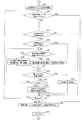
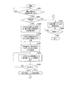
上記の構成において、電気自動車充電装置2の動作を以下に説明する。図10は、図1に示した電気自動車充電装置2の基本動作を示すフローチャートである。図11は、図10の動作に続く電気自動車充電装置2の基本動作を示すフローチャートである。
(Explanation of basic operation, high-speed charging → addition of charging power Pv, display during high-speed charging, display of remaining time)
In the above configuration, the operation of the electric
電気自動車充電装置2にて電気自動車3の蓄電池62を充電する際には、ユーザにより電気自動車充電装置2の電源がオンにされる。この電源オンにより、カウント値nを0にリセットする。次に、ユーザにより、充放電器53に備えられている充電用ケーブルが電気自動車3に接続される。これにより、充放電器53と蓄電池62とが接続される。また、電気自動車システム61と電気自動車充電装置2との通信が可能となる。なお、蓄電池62と充放電器53の接続は、通信によりお互いの正常動作、安全性を確認した後に、行うようにすることが好ましい。
When the electric
この状態において、電気自動車充電装置2では、電気自動車3の蓄電池62に対する充電指示を受けると(S11)、設定されている充電モードが高速充電モードか低速充電モードかを判定する(S12)。
In this state, when the electric
S12において、設定されている充電モードが低速充電モードであれば、低速充電モードによる充電を開始し(S13)、充電が完了すれば(S14)、処理を終了する。 In S12, if the set charging mode is the low speed charging mode, charging in the low speed charging mode is started (S13), and if the charging is completed (S14), the process is terminated.
一方、S12において、設定されている充電モードが高速充電モードであれば、記憶装置72の記憶内容を参照して、分電盤12への入力電力Pinについての住宅設置電気機器への供給電力Phと電気自動車への充電電力Pvとの振分け設定(供給電力Phset
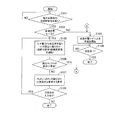
1、充電電力Pvset1)を確認し、かつ電力削減対象電気機器の設定の有無を判定する(S15)。
On the other hand, in S12, if the set charging mode is the high-speed charging mode, the stored power in the
1, the charging power Pvset1) is confirmed, and the presence / absence of setting of the power reduction target electric device is determined (S15).
S15での判定の結果、電力削減対象電気機器が設定されていなければ、各住宅設置電気機器の消費電力を一律に所定%削減する(S16)。 If the electric power reduction target electric device is not set as a result of the determination in S15, the power consumption of each house-installed electric device is uniformly reduced by a predetermined percentage (S16).
一方、S15での判定の結果、入力電力Pinについての振分け設定(供給電力Phset1、充電電力Pvset1)および電力削減対象電気機器が設定されていれば、その設定の内容にしたがって、住宅設置電気機器への供給電力Phが削減されるように、分電盤12への入力電力Pinを振り分ける。この場合、制御装置54の制御部71は、住宅設置電気機器群82の電力削減対象電気機器に対して消費電力の削減を指示する(S17)。これにより、電力削減対象電気機器では、高速充電モードの場合の予めの設定にしたがって消費電力を削減する。
On the other hand, as a result of the determination in S15, if the distribution setting (supply power Phset1, charging power Pvset1) for the input power Pin and the electric device targeted for power reduction are set, according to the contents of the setting, to the house-installed electric device The input power Pin to the
制御部71は、S16またはS17の処理の後、カウント値nをn+1とし(S18)、Ph電力モニター51によって測定される住宅設置電気機器への供給電力Ph1が供給電力Phの許容上限値以下であるか否かを判定する(S19)。なお、供給電力Phの許容上限値は、高速充電モードにおける入力電力Pinからの供給電力Phの振分け設定値(供給電力Phset1)である。
After the process of S16 or S17, the
S19の判定の結果、供給電力Ph1がその許容上限値(供給電力Phset1)よりも大きければ、カウント値nが2以下か否かを判定する(S20)。なお、この場合のnの値2は、2に限定されることなく、2以上の適当な値に設定されていればよい。
As a result of the determination in S19, if the supply power Ph1 is larger than the allowable upper limit value (supply power Phset1), it is determined whether or not the count value n is 2 or less (S20). In this case, the
S20での判定の結果、カウント値nが2以下であれば、S15に戻り、S16またはS17の処理およびS18の処理を繰り返す。なお、再度行うS16またはS17の処理において、住宅設置電気機器への供給電力Phの削減量は、処理の実行結果を確認する意味において前回と同じ値としてもよいものの、前回の値よりも若干多くすることが好ましい。 As a result of the determination in S20, if the count value n is 2 or less, the process returns to S15, and the process of S16 or S17 and the process of S18 are repeated. In the process of S16 or S17 performed again, the reduction amount of the supplied power Ph to the house-installed electrical equipment may be the same as the previous value in the sense of confirming the execution result of the process, but slightly larger than the previous value. It is preferable to do.
その後、S19の判定において供給電力Ph1がその許容上限値(供給電力Phset1)よりも大きく、S20の判定においてカウント値nが2よりも大きければ、制御部71は、入力電力Pinについての住宅設置電気機器への供給電力Phと電気自動車への充電電力Pvとの振り分けの再設定を促す旨の表示を表示装置55に行わせる。
After that, if the supply power Ph1 is larger than the allowable upper limit value (supply power Phset1) in the determination in S19 and the count value n is larger than 2 in the determination in S20, the
なお、上記表示は、例えば、「電気自動車への充電電力Pvの設定値を変更できません。充電電力Pvを再設定してください」といったものである。上記再設定は、ユーザに対して充電電力Pvを減少させる方向の設定を要求する意図のものである。また、上記表示に加えて、音声により上記表示内容をユーザに報知してもよい。 The above display is, for example, “The set value of the charging power Pv for the electric vehicle cannot be changed. Please reset the charging power Pv”. The resetting is intended to request the user to set the direction to decrease the charging power Pv. In addition to the above display, the display content may be notified to the user by voice.
S21の処理の後、制御部71は、入力装置56からのユーザによる充電電力Pvの再設定(入力電力Pinについての住宅設置電気機器への供給電力Phと電気自動車への充電電力Pvとの振り分けの再設定)の有無を判定し(S22)、所定時間を経過するまでに充電電力Pvの再設定の入力がなければ処理を終了する。一方、S22において、充電電力Pvの再設定の入力があれば、再設定された値に基づいて、S16またはS17の処理を行う。
After the process of S21, the
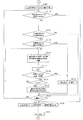
その後、S19の判定の結果、供給電力Ph1がその許容上限値以下となれば、制御部71は、カウント値nを0にリセットした後(S41)、図11のS23において、高速充電モードによる蓄電池62に対しての充電を開始する。
Thereafter, if the result of determination in S19 is that the supplied power Ph1 is less than or equal to the allowable upper limit value, the
ここで、第2配線遮断器群81、住宅設置電気機器群82およびコンセント群83において、高速充電モードによる電気自動車3の蓄電池62の充電中に、その旨を例えばLEDランプ121の点灯によって表示する構成である場合、LEDランプ121を点灯する。
Here, in the second
また、第2配線遮断器群81、住宅設置電気機器群82およびコンセント群83において、高速充電モードによる電気自動車3の充電中に、高速充電モードの残り時間を表示する構成である場合、それぞれの時間表示装置122に高速充電モードの残り時間を表示する。
In addition, when the second
この場合、制御装置54の制御部71は、前述のように、蓄電池62の残電力量情報、充電完了状態情報および電気自動車への充電電力Pv情報に基づいて、完了予測時間を計算し、第2配線遮断器群81、住宅設置電気機器群82およびコンセント群83に伝える。あるいは、制御部71は、高速充電モードの残り時間(完了予測時間)をカウントダウンしていき、カウントダウンごとに残り時間を第2配線遮断器群81、住宅設置電気機器群82およびコンセント群83に伝える。これに応じて、第2配線遮断器群81、住宅設置電気機器群82およびコンセント群83では、時間表示装置122に高速充電モードの残り時間を表示する。
In this case, as described above, the
S23での蓄電池62に対しての高速充電モードによる充電開始後に、制御装置54の制御部71は、ユーザにより入力装置56から低速充電モードへの変更指示が入力されているか否かを判定する(S24)。この判定の結果、低速充電モードへの変更指示が入力されていれば、低速充電モードへの移行処理を行い(S36)、カウント値nを0にリセットした後(S37)、S13に進んで低速充電モードによる充電を行う。
After starting charging of the
一方、S24の判定の結果、低速充電モードへの変更指示が入力されていなければ、制御部71は、入力装置56から電気自動車への充電電力Pvに対する追加要求が入力されたかどうかを判定する(S25)。なお、この判定は、高速充電モードによる蓄電池62に対しての充電の開始前に行ってもよい。
On the other hand, as a result of the determination in S24, if an instruction to change to the low-speed charging mode is not input, the
S25での判定の結果、電気自動車への充電電力Pvに対する追加要求が入力されていなければ、制御装置54の制御部71は、高速充電モードによる充電の完了まで充電を継続し、高速充電モードによる充電が完了すれば(S35)、S36の処理へ進み、それ以降の処理を行う。また、S35において高速充電モードによる充電が完了していなければ、S24に戻ってそれ以降の処理を行う。
As a result of the determination in S25, if an additional request for the charging power Pv to the electric vehicle is not input, the
一方、S25での判定の結果、電気自動車への充電電力Pvに対する追加要求が入力されていれば、制御装置54の制御部71は、充電電力Pvの追加が可能かどうかを判定する(S26)。この判定では、その時点における住宅設置電気機器への供給電力Ph1が、充電電力Pvの追加要求が行われた場合の住宅設置電気機器への供給電力Phset2を超える場合に、充電電力Pvの追加が不可能と判定される。
On the other hand, as a result of the determination in S25, if an addition request for the charging power Pv to the electric vehicle is input, the
例えば、充電電力Pv1が5kWで、供給電力Ph1が3.5kWのとき、充電電力Pvset2を7kWにすると、入力電力Pinの上限値が10kWの条件下では供給電力Phset2は3kWとなる。この場合、供給電力Ph1が供給電力Phset2を超えるので、充電電力Pvの追加が不可能と判定される。逆に、Ph1が1kWの場合、Ph1はPhset2よりも小さいので、充電電力Pvの追加が可能と判定される。 For example, when the charging power Pv1 is 5 kW and the supply power Ph1 is 3.5 kW, and the charging power Pvset2 is 7 kW, the supply power Phset2 is 3 kW under the condition that the upper limit value of the input power Pin is 10 kW. In this case, since the supplied power Ph1 exceeds the supplied power Phset2, it is determined that the charging power Pv cannot be added. On the contrary, when Ph1 is 1 kW, since Ph1 is smaller than Phset2, it is determined that charging power Pv can be added.
なお、充電電力Pvの追加要求は、充電電力Pvset1を充電電力Pvset2に増
加するという要求である。また、供給電力Ph1が、充電電力Pvの追加要求が行われた場合の住宅設置電気機器への供給電力Phset2を超える場合とは、供給電力Ph1を削減せずに、充電電力Pvset2を設定すると入力電力Pinが上限値(例えば10kW)を超える場合である。
The request for adding the charging power Pv is a request for increasing the charging power Pvset1 to the charging power Pvset2. In addition, when the supply power Ph1 exceeds the supply power Phset2 to the home-installed electrical equipment when the request for adding the charge power Pv is made, it is input when the charge power Pvset2 is set without reducing the supply power Ph1. This is a case where the power Pin exceeds an upper limit value (for example, 10 kW).
S26での判定の結果、充電電力Pvの追加が可能であれば、住宅設置電気機器への供給電力Phを追加削減することなく、充電電力Pvを追加する(S27)。すなわち、充電電力Pvset1を充電電力Pvset2に切り替えて増加させる。その後、S35に進み、それ以降の処理を行う。 As a result of the determination in S26, if it is possible to add the charging power Pv, the charging power Pv is added without additionally reducing the power supply Ph supplied to the home-installed electrical equipment (S27). That is, the charging power Pvset1 is switched to the charging power Pvset2 and is increased. Then, it progresses to S35 and performs the process after it.
一方、S26での判定の結果、充電電力Pvの追加が不可能であれば、住宅設置電気機器への供給電力Phをさらに削減する必要がある。そこで、制御部71は、記憶装置72の記憶内容を参照して、住宅設置電気機器群82の住宅設置電気機器に対して、電力追加削減対象電気機器の設定(指定)が行われているか否かを判定する(S28)。
On the other hand, if it is not possible to add the charging power Pv as a result of the determination in S26, it is necessary to further reduce the power supply Ph to the house-installed electrical device. Therefore, the
S28での判定の結果、電力追加削減対象電気機器の設定が行われていなければ、住宅設置電気機器群82の各住宅設置電気機器の消費電力を一律に所定%追加削減する(S29)。
As a result of the determination in S28, if the electric power reduction target electric device is not set, the power consumption of each electric device installed in the
一方、S28の判定の結果、電力追加削減対象電気機器の設定が行われていれば、制御装置54の制御部71は、電力追加削減対象電気機器に設定されている優先順位の順序にて電力追加削減対象電気機器(住宅設置電気機器)に対して消費電力の削減を指示する。これにより、その電力追加削減対象電気機器において消費電力が追加削減される。
On the other hand, as a result of the determination in S28, if the setting of the electric power reduction target electric device is performed, the
この場合、先ずは優先順位第1位の電力追加削減対象電気機器に対して消費電力の削減が指示され、優先順位第1位の電力追加削減対象電気機器において消費電力が追加削減される(S30)。なお、上記優先順位に関しては、一つの優先順位(例えば優先順位第1位)に複数の電力追加削減対象電気機器が設定されていてもよい。 In this case, first, the electric power reduction target electric device with the highest priority is instructed to reduce the power consumption, and the electric power consumption is additionally reduced in the electric power reduction target with the highest priority (S30). ). In addition, regarding the said priority, the some electric equipment for electric power addition reduction reduction may be set to one priority (for example, priority order 1st).
次に、制御部71は、S29またはS30の処理の後、カウント値nをn+1とし(S31)、Ph電力モニター51によって測定される住宅設置電気機器への供給電力Ph1が供給電力Phの許容上限値以下であるか否かを判定する(S32)。なお、ここでの供給電力Phの許容上限値は、高速充電モードにおいて充電電力Pvを追加した場合の入力電力Pinからの供給電力Phの振分け設定値(供給電力Phset2)である。
Next, after the process of S29 or S30, the
S32での判定の結果、供給電力Ph1がその許容上限値(供給電力Phset2)よりも大きければ、カウント値nが2以下であるか否かを判定する(S33)。なお、この場合のnの値2は、2に限定されることなく、2以上の適当な値に設定されていればよい。
As a result of the determination in S32, if the supplied power Ph1 is larger than the allowable upper limit value (supplied power Phset2), it is determined whether or not the count value n is 2 or less (S33). In this case, the
S33での判定の結果、カウント値nが2以下であれば、S28に戻り、S29またはS30の処理からS33の処理を繰り返す。なお、再度行うS29の処理において、住宅設置電気機器への供給電力Phの削減量は、前回と同じ値としてもよいものの、前回の値よりも若干多くすることが好ましい。また、再度行うS30の処理においては、優先順位第2位の電力追加削減対象電気機器に対して消費電力の削減が指示され、優先順位第2位の電力追加削減対象電気機器において消費電力が追加削減される。 As a result of the determination in S33, if the count value n is 2 or less, the process returns to S28, and the process of S33 is repeated from the process of S29 or S30. In the process of S29 performed again, the amount of reduction in the power supply Ph supplied to the house-installed electrical equipment may be the same as the previous value, but is preferably slightly larger than the previous value. Further, in the process of S30 performed again, the electric power reduction target is instructed to the electric power reduction target device with the second highest priority, and the electric power is added to the electric power reduction object electric device with the second priority. Reduced.
次に、S32の判定において、供給電力Ph1がその許容上限値(供給電力Phset2)以下となれば、充電電力Pvの追加が可能であるので、充電電力Pvを追加する(S27)。すなわち、充電電力Pvset1を充電電力Pvset2に切り替えて増加させ
る。その後、S35に進み、それ以降の処理を行う。
Next, in the determination of S32, if the supplied power Ph1 is equal to or lower than the allowable upper limit value (supplied power Phset2), the charging power Pv can be added, so the charging power Pv is added (S27). That is, the charging power Pvset1 is switched to the charging power Pvset2 and is increased. Then, it progresses to S35 and performs the process after it.
一方、S32の判定において、供給電力Ph1がその許容上限値(供給電力Phset2)よりも大きく、S33の判定においてカウント値nが2よりも大きければ、制御部71は、充電電力Pvの追加が不可である旨の表示を表示装置55に行わせる。これに加えて、入力電力Pinについての住宅設置電気機器への供給電力Phと電気自動車への充電電力Pvとの振り分け(供給電力Phset2、充電電力Pvset2)の再設定を促す旨の表示を表示装置55に行わせる。
On the other hand, if the supply power Ph1 is larger than the allowable upper limit value (supply power Phset2) in the determination of S32 and the count value n is larger than 2 in the determination of S33, the
なお、上記再設定は、ユーザに対して充電電力Pvを減少させる方向の設定を要求する意図のものである。また、上記表示に加えて、音声により上記表示内容をユーザに報知してもよい。 The resetting is intended to request the user to set the direction to decrease the charging power Pv. In addition to the above display, the display content may be notified to the user by voice.
次に、制御部71は、S35において高速充電モードによる充電が完了したか否かを判定し、充電が完了していればS36へ進む一方、充電が完了していなければ、S24に戻ってそれ以降の処理を繰り返す。
Next, the
なお、S34での表示により、ユーザにて入力電力Pinについての住宅設置電気機器への供給電力Phと電気自動車への充電電力Pvとの振り分け(供給電力Phset2、充電電力Pvset2)が変更された場合、この変更後の設定は、記憶装置72に記憶される。その後、変更後の設定は、S26およびS32等の処理に反映される。
When the user changes the distribution (supply power Phset2, charge power Pvset2) between the power supply Ph supplied to the house-installed electrical device and the charge power Pv to the electric vehicle with respect to the input power Pin by the display in S34 The changed setting is stored in the
ここで、S36の低速充電モードへの移行処理について説明する。電気自動車充電装置2において、蓄電池62に対する充電モードが高速充電モード(充電優先モード)から低速充電モード(普通充電モード)に切り替われば、電気自動車への充電電力Pvが低下する。したがって、住宅設置電気機器への供給電力Phは、高速充電モードの前の状態に復帰させることができる。そこで、低速充電モードへの移行処理では、高速充電モードにおいて蓄電池62が満充電電圧に達し、充電完了となると、住宅設置電気機器への供給電力Phの削減制御を契約電力以上にならないように、入力電力Pinを上限として緩めていく。この低速充電モードへの移行処理は、高速充電モードによる充電完了状態に限らず、タイマー設定により高速充電モードを実行している場合のタイマー終了や、入力装置56からのユーザ指示による高速充電モードの終了などの場合においても、高速充電モードから低速充電モード(普通充電モード)切り替わる際に、同様に行われる。
Here, the transition process to the low-speed charging mode in S36 will be described. In the electric
また、高速充電モードから低速充電モードへの移行に関し、高速充電モードでは、蓄電池62の過充電を防止するために、満充電が蓄電池62の本来の満充電の状態よりも低目に設定されている。そこで、電気自動車充電装置2では、高速充電モードによる充電が完了した後、低速充電モードによる充電を行って、蓄電池62を本来の満充電の状態に充電するようにしている。
Further, regarding the transition from the fast charge mode to the slow charge mode, in the fast charge mode, the full charge is set lower than the original full charge state of the
低速充電モード(普通充電モード)による充電は、リチウムイオン電池などの充電において一般に行われる定電流−定電圧制御(CC−CV制御)である。例えば、定電流時の充電電流は概略1kWの充電電力に相当する(電池電圧が333Vの場合には3A)。 Charging in the low-speed charging mode (normal charging mode) is constant current-constant voltage control (CC-CV control) that is generally performed when charging a lithium ion battery or the like. For example, the charging current at a constant current corresponds to approximately 1 kW of charging power (3 A when the battery voltage is 333 V).
定電圧制御は、例えば、蓄電池62の電圧が満充電電圧以上にならないように、充電電流量を制御する。蓄電池62では充電が進めば電池電圧は上昇していく。このため、例えば、350Vが満充電電圧の場合、350V以上にならないように、充電電流を徐々に下げていく。蓄電池62には内部インピーダンスがあるため、充電電流が下がると、抵抗による電圧低下が小さくなり、電池端子の電池電圧が低下する。定電圧制御では、充電電流が小さくなり、所定の電流値以下(例えば、1A以下)になると、充電動作を停止する。
In the constant voltage control, for example, the amount of charging current is controlled so that the voltage of the
(充電スケジュールが設定されている場合の動作説明)
次に、充電スケジュールが設定されている場合の電気自動車充電装置2の動作について説明する。図12は、図1に示した電気自動車充電装置2の充電スケジュールが設定されている場合の動作を示すフローチャートである。
(Explanation of operation when charging schedule is set)
Next, the operation of the electric
図12において、S51,S52の動作は図10のS11,S12の動作に対応し、S53,S54の動作は図10のS13,S14の動作に対応し、S56は図10のS15から図11のS34の動作、および図10のS41の動作に対応し、S59は図11のS36の処理に対応する。 In FIG. 12, the operations of S51 and S52 correspond to the operations of S11 and S12 of FIG. 10, the operations of S53 and S54 correspond to the operations of S13 and S14 of FIG. 10, and S56 corresponds to the operations of S15 to FIG. This corresponds to the operation of S34 and the operation of S41 of FIG. 10, and S59 corresponds to the processing of S36 of FIG.
図12において、電気自動車充電装置2では、電気自動車3の蓄電池62に対する充電指示を受けると(S51)、設定されている充電モードが高速充電モードか低速充電モードかを判定する(S52)。
In FIG. 12, when the charging instruction for the
S52において、設定されている充電モードが低速充電モードであれば、低速充電モードによる充電を行い(S53)、充電が完了すれば(S54)、処理を終了する。 In S52, if the set charging mode is the low speed charging mode, charging is performed in the low speed charging mode (S53), and if the charging is completed (S54), the process is terminated.
一方、S52において、設定されている充電モードが高速充電モードであれば、制御装置54の制御部71は、記憶装置72に記憶されている充電スケジュールを取得する(S55)。この充電スケジュールは、ユーザが入力装置56を操作することにより予め設定されたものである。
On the other hand, if the set charging mode is the fast charging mode in S52, the
次に、制御装置54の制御部71は、取得した充電スケジュールに基づいて、電池残量測定部63による電気自動車3の蓄電池62の充電を行う(S56)。
Next, the
その後、制御装置54の制御部71は、高速充電モードによる充電が完了したか否かを判定し(S57)、充電が完了していれば、低速充電モードへの移行処理を行った後(S59)、S53に進んで低速充電モードによる充電を行う。
Thereafter, the
S57での充電完了は、充電スケジュールを参照して判定する。例えば、充電スケジュールにおいて、蓄電池62の充電完了の条件として、満充電に対する充電量が所定%(例えば80%あるいは60%など)に到達したときと設定されていれば、その蓄電池62の充電量がその条件を満たしたときに充電完了とする。
Completion of charging in S57 is determined with reference to the charging schedule. For example, in the charging schedule, if the charging amount for the
また、充電スケジュールにおいて、充電時間が設定されている場合、あるいは充電の開始時刻と終了時刻が設定されている場合には、充電が設定されている時間だけ行われたと、あるいは終了時刻に到達したときに充電完了とする。 In the charging schedule, when the charging time is set, or when the charging start time and end time are set, the charging is performed for the set time or the end time is reached. Sometimes charging is complete.
また、充電スケジュールにおいては、例えば高速充電モードによる蓄電池62の充電を満充電に対する所定%まで(例えば60%まで)とし、満充電までの残り%分(例えば40%分)を低速充電モードにより充電するといった設定が可能である。この場合には、蓄電池62が満充電に対する所定%まで充電されて時点において、蓄電池62に対する充電モードを高速充電モードから低速充電モードに切り替える(S58)。
In the charging schedule, for example, charging of the
これにより、S53およびS54の処理を行い、低速充電モードにより蓄電池62が満充電まで充電されると、処理を終了する。
Thereby, the process of S53 and S54 is performed, and the process ends when the
本実施の形態の電気自動車充電装置2では、上記のように、高速充電モードによる充電動作の場合に、低速充電モードによる充電動作の場合よりも、住宅設置電気機器への供給
電力が削減され、電気自動車3への充電電力Pvが増加するように、住宅設置電気機器への供給電力が制御される。これにより、使用電力上限値、すなわち契約電力が設定されている条件下において、高速充電モードによる電気自動車3の蓄電池62に対しての充電を適切に行うことができる。
In the electric
また、高速充電モードにおいては、住宅設置電気機器への供給電力Phを削減し、負荷変動に影響されること無く、充電電力Pvを安定した定電力で高速に充電することができる。したがって、電気自動車の蓄電池62を確実に充電することができ、また、蓄電池62の充電容量の測定を容易にかつ誤差が少なく行うことができる。
Further, in the high-speed charging mode, it is possible to reduce the supply power Ph to the home-installed electrical equipment and charge the charging power Pv at a high speed with a stable constant power without being affected by load fluctuations. Therefore, the
また、高速充電モードにおいては、受電設備としての分電盤12に接続されている住宅設置電気機器の消費電力が抑制されるように住宅設置電気機器を制御している。したがって、例えば電力削減対象電気機器毎に消費電力の抑制量を設定するといったように、住宅設置電気機器の消費電力の抑制に対して、柔軟な制御が可能となる。
Further, in the high-speed charging mode, the house-installed electric device is controlled so that the power consumption of the house-installed electric device connected to the
また、高速充電モードにおける電力削減対象電気機器をユーザが入力装置56を操作して指定することができるので、ユーザの希望を反映して、適当な住宅設置電気機器を電力削減対象電気機器として設定することができる。
In addition, since the user can designate the electric device targeted for power reduction in the high-speed charging mode by operating the
また、入力装置56から充電電力Pvの追加要求が入力された場合には、充電電力Pvが追加要求に応じた値となるまで、ユーザにより予め設定された優先順位に従って電力追加削減対象電気機器への供給電力が削減されるように、電力追加削減対象電気機器が制御される。これにより、高速充電モードにおいて、充電電力Pvの追加要求が生じた場合には、ユーザの希望を反映した優先順位に従って電力追加削減対象電気機器に対する消費電力削減のための制御を行うことができる。
In addition, when a request for adding charging power Pv is input from the
また、高速充電モードによる充電動作を記憶装置72に記憶されている設定情報が示す実行時間において実行させることができる。これにより、ユーザは、入力装置56を操作して高速充電モードによる充電動作の実行時間を設定することにより、例えば電気自動車3を使用しない時間など、希望する時間だけ電気自動車充電装置2により高速充電モードによる蓄電池の充電を行わせることができる。
Further, the charging operation in the fast charging mode can be executed at the execution time indicated by the setting information stored in the
また、電気自動車3から、蓄電池62の充電により変化する残電力量を示す情報を取得し、蓄電池62の残電力量が記憶装置72に記憶されている上限値情報にて示される値に到達した場合に、高速充電モードによる充電動作を終了させるように制御することができる。したがって、ユーザは、入力装置56を操作して、蓄電池62の満充電に対する充電量の上限値を設定することにより、蓄電池62の残電力量が希望する量となるように、電電気自動車充電装置2にて蓄電池62を充電させることができる。
Moreover, the information which shows the remaining electric energy which changes with charge of the
また、高速充電モードによる充電動作状態であることが、住宅設置電気機器、第2配線遮断器23、200Vコンセント42、100Vコンセント43に設けられたLEDランプ(報知手段)121によって報知されるので、ユーザは、高速充電モードによる充電動作状態であることを容易に知ることができる。
Moreover, since it is alert | reported by the LED lamp (notification means) 121 provided in the house installation electric equipment, the
また、住宅設置電気機器、第2配線遮断器23、200Vコンセント42、100Vコンセント43に設けられた時間表示装置(時間表示手段)122にて、高速充電モードによる充電動作時間や、充電動作の開始時刻あるいは終了時刻などの、高速充電モードによる充電動作に関する時間表示が行われる。したがって、ユーザは、時間表示装置122により高速充電モードによる充電動作に関する時間を容易に知ることができる。
In addition, the time display device (time display means) 122 provided in the house-installed electrical equipment, the
ここで、第2配線遮断器23の構成について説明する。図19は図1に示した第2配線遮断器23の構成を示す回路図である。
Here, the configuration of the
第2配線遮断器23は、図19に示すように、開閉器301、第1FET(遮断回路)302、第2FET(遮断回路)303、電流検出器304、電流検出判定回路305、引き剥がし器306およびFET駆動回路(遮断回路)307を備えている。
As shown in FIG. 19, the
第2配線遮断器23内には、第1および第2の2本の給電線308,309が通っている。これら第1および第2給電線308,309の入力側は、分電盤12を通る給電線41のN線(中性線)およびL1線またはL2線に接続される。また、出力側は、住宅設置電気機器(家電機器)に接続される。第1FET(遮断回路)302、第2FET(遮断回路)303は中性線には配置されず、L1線またはL2線に接続される。
In the
開閉器301は、開閉動作により第1および第2給電線308,309を遮断および導通させるように、第1および第2給電線308,309に設けられている。図19に示す第1および第2給電線308,309は図2に示したL1線とL2線であり、中性線(ア
ース)は遮断しない接続になっている。第1FET302および第2FET303は、い
ずれか一方の給電線、例えば第1給電線308において、開閉器301の下流側(住宅設置電気機器(家電機器)側)位置に、互いに直列に設けられている。電流検出器304は、いずれか一方の給電線、例えば第1給電線308において、開閉器301の上流側(分電盤側)位置に設けられている。
The
引き剥がし器306は、開閉器301を開動作させる。なお、開閉器301の開閉動作は、手動によっても行うことができる。
The
電流検出判定回路305は、電流検出器304によって検出される第1給電線308を流れる電流量が所定量以上となった場合に、引き剥がし器306が開閉器301の開動作を行うように制御する。開閉器301の開動作を行った場合、第1および第2給電線308,309が遮断され、第2配線遮断器23に接続されている住宅設置電気機器への電力供給が遮断される。
The current
第1FET302および第2FET303は、オン/オフ動作により、第1給電線308を導通/非導通にさせる。この場合、開閉器301が閉動作を行っている状態において、第1FET302および第2FET303の両者がオンとなった場合、第1給電線308は導通となる。また、第1FET302および第2FET303の両方がオフとなった場合、第1給電線308は非導通(遮断状態)となる。
The
FET駆動回路307は、制御装置54からの制御信号(オン/オフ信号)に基づいて、第1FET302および第2FET303の導通、非導通を制御する。
The
したがって、電流検出判定回路305およびFET駆動回路307は、図3に示した第2配線遮断器群81の制御部101に相当し、第1FET302および第2FET303並びに開閉器301は遮断駆動装置102に相当する。
Therefore, the current
なお、図19に示した第1FET302、第2FET303およびFET駆動回路307を備えた構成は、コンセント(図2に示した200Vコンセント42および100Vコンセント43)に設けられていてもよい。その場合、コンセントは、電流センサと電圧センサからなる電力モニター回路を備える。また、電力モニター値を受信し、制御部71へ送信することで、コンセント毎の消費電力を制御部71へ通知する通信機能を備える。これにより、制御部71は、高速充電モード時において、新たに消費電力が増加し、供給電
力Phが設定値を超えてしまう場合に、コンセントへの通電を遮断するように制御する。
The configuration including the
また、前述のように、高速充電モード時において、住宅設置電気機器が接続されていないコンセント(200Vコンセント42、100Vコンセント43)、もしくはそのコンセントのみに接続されている第2配線遮断器23については、第1FET302および第2FET303をオフさせるように制御してもよい。これは、空いているコンセントに新たに電気機器が接続されてコンセントから給電が行われることにより、住宅設置電気機器の消費電力が増加する事態を防止するための制御である。
As described above, in the high-speed charging mode, the outlet (
この場合、第1FET302および第2FET303のオフは、制御部71からオフのための制御信号を受けたFET駆動回路307によって行われる。
In this case, the
なお、制御部71は、コンセントからの消費電力の情報により、消費電力が0の場合は空いているコンセントとして、高速充電モード時にオフすることができる。コンセントからの消費電力が0ではない場合は、住宅設置電気機器が接続されているため、すぐにオフにせず、供給電力Phが設定値を上回った場合に、オフするように制御することができる。
In addition, the
また、以上の実施の形態においては、供給電力Phが高速充電中に設定値を上回ったときにコンセント毎に遮断する例について示した。しかしながら、契約電力Pcを超えないように充電電力Pvを低減し、電気自動車充電装置2の表示装置55に高速充電電力が確保されていない内容をユーザに伝え、消費電力の削減を促すようにしても良い。その場合、制御部71は充放電器53へ充電電流値を低減するように指示をする。このような制御にすることで、住宅設置家電機器がユーザの知らないところでオフされることがなく、一時的に家電機器の消費電力が上がるような場合でも、家電機器を安定して動作させることができる。ユーザへの通知は表示装置55での表示だけでなく、アラーム音や音声などで通知することが好ましい。この場合、ユーザはアラームに応じて、家電機器の消費電力を削減するか、電気自動車3への充電電力Pvの設定値を削減するかを選択し、対応することができる。
Moreover, in the above embodiment, the example which interrupts | blocks for every outlet when the supply electric power Ph exceeded the setting value during the high-speed charge was shown. However, the charging power Pv is reduced so as not to exceed the contract power Pc, and the content that the high-speed charging power is not ensured is transmitted to the
〔実施の形態2〕
本発明の他の実施の形態を図面に基づいて以下に説明する。本実施の形態の電気自動車充電装置2では、高速充電モードにおいて、住宅設置電気機器への供給電力Phを削減する場合に、個々の住宅設置電気機器の消費電力を制御するのではなく、住宅設置電気機器が接続されている第2配線遮断器23を遮断するようになっている。以下、この場合の電気自動車充電装置2の構成および動作について詳細に説明する。
[Embodiment 2]
Another embodiment of the present invention will be described below with reference to the drawings. In the electric
図1に示すように、分電盤12には複数の第2配線遮断器23が設けられ、第2配線遮断器23毎に、住宅設置電気機器としての洗濯乾燥機31、照明32、エアコン33、オーディオ機器34、パソコン35、およびテレビ36が接続されている。制御装置54の制御信号は、各第2配線遮断器23に入力され、その制御信号によって各第2配線遮断器23を遮断できるようになっている。
As shown in FIG. 1, the
具体的には、図3に示すように、制御装置54の制御部71からの第2配線遮断器23の遮断を指示する制御信号は、第2配線遮断器群81のいずれかの第2配線遮断器23に入力される。制御信号が入力された第2配線遮断器23では、制御部101が制御部71からの制御信号を受けて、遮断駆動装置102を駆動するように制御する。これにより、その第2配線遮断器23が遮断される。したがって、遮断された第2配線遮断器23に接続されている住宅設置電気機器への電力供給が遮断される。
Specifically, as shown in FIG. 3, the control signal instructing the interruption of the
なお、図1の例では、一つの第2配線遮断器23に一つの住宅設置電気機器が接続されている構成を示しているが、一つの第2配線遮断器23に複数の住宅設置電気機器が接続されている構成であってもよい。
In the example of FIG. 1, a configuration in which one home-installed electrical device is connected to one
(電力削減内容)
前述したように、入力装置56に対するユーザの操作により、高速充電モードが設定された場合には、住宅設置電気機器への供給電力Phの削減設定が行われる。この設定内容は、記憶装置72に記憶される。具体的には、例えば前述した実施の形態の場合と同様に、高速充電モードにおいて、住宅設置電気機器への供給電力Phに5kWが振り分け振られ、電気自動車への充電電力Pvに5kWが振り分けられる。
(Content of power reduction)
As described above, when the high-speed charging mode is set by the user's operation on the
本実施の形態の電気自動車充電装置2では、高速充電モードにおいて、住宅設置電気機器への供給電力Phを削減するために、第2配線遮断器群81の第2配線遮断器23のうち、一部の第2配線遮断器23が遮断される。これにより、高速充電モードための電気自動車への充電電力Pvが確保され、高速充電モードによる電気自動車3の蓄電池62に対しての充電を適切に行えるようになる。
In the electric
高速充電モードにおいて遮断される遮断対象第2配線遮断器は、ユーザにより入力装置56を操作して設定される。この場合、ユーザはどの第2配線遮断器23にどの住宅設置電気機器が接続されているかを確認して設定を行う。なお、制御部71は、遮断対象第2配線遮断器の設定がユーザにて行われる場合に、第2配線遮断器23と第2配線遮断器23に接続されている住宅設置電気機器との対応関係を示し、かつ遮断対象第2配線遮断器を指定するためのユーザインターフェースを表示装置55に表示させるようにしてもよい。この表示を行うために、第2配線遮断器23と第2配線遮断器23に接続されている住宅設置電気機器との対応関係は、予めユーザにより入力装置56から入力され、記憶装置72に記憶される。
The second wiring breaker to be interrupted that is interrupted in the fast charge mode is set by operating the
例えば、図1に示した複数の第2配線遮断器23では、エアコン33およびオーディオ機器34が接続されている各第2配線遮断器23が遮断対象第2配線遮断器として設定されてもよい。
For example, in the plurality of
(充電電力Pvの追加)
次に、高速充電モードにおいて、ユーザの操作により入力装置56から電気自動車への充電電力Pvに対する追加要求が入力された場合に対応する電気自動車充電装置2の構成について説明する。
(Addition of charging power Pv)
Next, the configuration of the electric
電気自動車への充電電力Pvの追加要求は、ユーザがさらに充電時間の短縮を希望する場合に、入力装置56を操作して入力される。充電電力Pvの追加要求の入力は、高速充電モードを選択した後、かつ電気自動車3への充電が開始される前の時点、あるいは高速充電モードによる充電を行っている途中の時点のいずれの時点に行われてもよい。
The request for adding the charging power Pv to the electric vehicle is input by operating the
充電電力Pvの追加要求が入力された場合の充電電力Pvの追加量、すなわち入力電力Pin10kWの振り分けは、例えば、前述した実施の形態の場合と同様、住宅設置電気機器への供給電力Phに3kW、電気自動車への充電電力Pvに7kWとなる。この振り分けの設定の入力は、充電電力Pvの追加要求が入力される前の時点、あるいは充電電力Pvの追加要求が入力された後の時点のいずれの時点に行われてもよい。入力装置56から上記振分け設定が入力されると、制御部71はその設定内容を記憶装置72に記憶させる。
The additional amount of the charging power Pv when the request for adding the charging power Pv is input, that is, the distribution of the
(追加の電力削減内容)
充電電力Pvの追加要求が入力された場合において、その時点における住宅設置電気機器への供給電力Phが、充電電力Pvの追加要求に伴い予めの設定に応じて削減された場合の住宅設置電気機器への供給電力Phを超える場合、すなわち入力電力Pinが上限値を超える場合、住宅設置電気機器への供給電力Phへの追加削減が必要となる。この場合には、遮断対象第2配線遮断器に加えて、追加遮断対象第2配線遮断器が遮断される。この場合、制御装置54の制御部71は、追加遮断対象第2配線遮断器としての優先順位の高いものから順次遮断する。
(Additional power reduction content)
When an additional request for charging power Pv is input, the electric power Ph to be supplied to the house-installed electrical device at that time is reduced according to a preset setting in accordance with the request for adding charge power Pv. When the supply power Ph is exceeded, that is, when the input power Pin exceeds the upper limit value, an additional reduction to the supply power Ph to the house-installed electrical equipment is required. In this case, in addition to the breaking target second wiring breaker, the additional breaking target second wiring breaker is blocked. In this case, the
追加遮断対象第2配線遮断器および追加遮断対象第2配線遮断器の優先順位の設定は、ユーザによる入力装置56の操作により行われ、設定内容は記憶装置72に記憶される。例えば、図1に示した複数の第2配線遮断器23では、テレビ36および洗濯機31が接続されている各第2配線遮断器23が追加遮断対象第2配線遮断器として設定されてもよい。また、優先順位は、テレビ36が接続されている第2配線遮断器23、洗濯機31が接続されている第2配線遮断器23の順序であってもよい。
The priority order of the additional circuit breaker second wiring breaker and the additional circuit breaker second wiring circuit breaker is set by the user operating the
追加遮断対象第2配線遮断器に関する設定を行う場合、制御部71は、ユーザにて操作される入力装置56からの要求に応じて、第2配線遮断器23と第2配線遮断器23に接続されている住宅設置電気機器との対応関係、および既に設定されている遮断対象第2配線遮断器を示し、かつ追加遮断対象第2配線遮断器を指定するためのユーザインターフェースを表示装置55に表示させるようにしてもよい。
When making settings related to the additional wiring breaker second wiring breaker, the
電気自動車充電装置2は、高速充電モードが設定されている状態において、Ph電力モニター51およびPv電力モニター52により、住宅設置電気機器への供給電力Phおよび電気自動車への充電電力Pvを監視している。この状態において、制御装置54の制御部71は、住宅設置電気機器への供給電力Phの追加削減が必要と判断すると、優先順位第1位の追加遮断対象第2配線遮断器を遮断する。これにより、住宅設置電気機器への供給電力Phは、優先順位第1位の追加遮断対象第2配線遮断器に接続されている住宅設置電気機器の消費電力の分だけ削減され、その分、電気自動車への充電電力Pvが増加することになる。
In the state where the high-speed charging mode is set, the electric
制御装置54の制御部71では、Ph電力モニター51が示す値から、優先順位第1位の追加遮断対象第2配線遮断器の遮断により、住宅設置電気機器への供給電力Phが電力追加削減要求の設定値に達したか(電気自動車への充電電力Pvの追加分を確保できたか)どうかを判断する。その結果、住宅設置電気機器への供給電力Phが電力追加削減要求の設定値に達していなければ、優先順位第2位の追加遮断対象第2配線遮断器を遮断する。この処理は、住宅設置電気機器への供給電力Phが電力追加削減要求の設定値に達するまで、順次下位の優先順位の追加遮断対象第2配線遮断器に対して繰り返していく。
In the
(高速充電モード状態の表示、高速充電の残時間表示)
本実施の形態においても、前述の実施の形態の場合と同様に、第2配線遮断器群81、住宅設置電気機器群82およびコンセント群83では、高速充電モードによる電気自動車3の充電中に、その旨をそれぞれの表示装置103、表示装置94および表示装置112、すなわちLEDランプ121に表示するようになっていてもよい。また、前述の実施の形態の場合と同様に、第2配線遮断器群81、住宅設置電気機器群82およびコンセント群83では、高速充電モードによる電気自動車3の充電中に、それぞれの表示装置103、表示装置94および表示装置112、すなわち時間表示装置122に高速充電モードの残り時間を表示するようになっていてもよい。また、遮断機が遮断されているとき、遮断機が遮断されている状態や遮断される時間をLEDランプ121や時間表示装置122で表示することが好ましい。
(Display of fast charge mode status and remaining time of fast charge)
Also in the present embodiment, as in the case of the above-described embodiment, in the second
(充電スケジュール、高速充電モードのタイマー設定)
また、蓄電池62の充電完了を満充電に対する80%あるいは60%とすることや、例えば高速充電モードによる蓄電池62の充電を満充電に対する60%までとし、満充電までの残り40%を低速充電モードにより充電するといった充電スケジュールを設定できる点、さらには、高速充電モードによる蓄電池62の充電をユーザにより設定された所定時間だけ行うように充電スケジュールを設定できる点についても、前述の実施の形態の場合と同様である。
(Charge schedule, fast charge mode timer setting)
Further, the charging completion of the
(動作の説明)
上記の構成において、本実施の形態の電気自動車充電装置2の動作を以下に説明する。図13は、本実施の形態における、図1に示した電気自動車充電装置2の基本動作を示すフローチャートである。図14は、図13の動作に続く、本実施の形態における電気自動車充電装置2の基本動作を示すフローチャートである。
(Description of operation)
In the above configuration, the operation of the electric
電気自動車充電装置2にて電気自動車3の蓄電池62を充電する際には、ユーザにより、電気自動車充電装置2の電源がオンにされ、充放電器53に備えられている充電用ケーブルが電気自動車3に接続される。これにより、充放電器53と蓄電池62とが接続される。また、電気自動車システム61と電気自動車充電装置2との通信が可能となる。なお、蓄電池62と充放電器53の接続は、通信によりお互いの正常動作、安全性を確認した後に、行うようにすることが好ましい。
When charging the
この状態において、図13に示すように、電気自動車充電装置2では、電気自動車3の蓄電池62に対する充電指示を受けると(S101)、設定されている充電モードが高速充電モードか低速充電モードかを判定する(S102)。
In this state, as shown in FIG. 13, when the electric
S102において、設定されている充電モードが低速充電モードであれば、低速充電モードによる充電を開始し(S103)、充電が完了すれば(S104)、処理を終了する。 In S102, if the set charging mode is the low speed charging mode, charging in the low speed charging mode is started (S103), and if the charging is completed (S104), the process is terminated.
一方、S102において、設定されている充電モードが高速充電モードであれば、制御装置54の制御部71は、記憶装置72の記憶内容を参照して、高速充電モードの場合の、分電盤12への入力電力Pinについての住宅設置電気機器への供給電力Phと電気自動車への充電電力Pvとの振分け設定の内容を確認する。さらにその振分け設定の内容にしたがって、住宅設置電気機器への供給電力Phが削減されるように、分電盤12への入力電力Pinを振り分ける。この場合、制御装置54の制御部71は、第2配線遮断器群81の遮断対象第2配線遮断器を遮断する(S105)。これに伴い、遮断対象第2配線遮断器に接続されている住宅設置電気機器への電力供給が遮断される。これにより、住宅設置電気機器への電力供給が遮断された分、電気自動車への充電電力Pvを増加させることができる。
On the other hand, in S102, if the set charging mode is the high-speed charging mode, the
制御部71は、S105の処理の後、Ph電力モニター51によって測定される住宅設置電気機器への供給電力Phがこの供給電力Phの許容上限値以下か否かを判定する(S106)。なお、供給電力Phの許容上限値は、高速充電モードにおける入力電力Pinからの供給電力Phの振分け設定値(供給電力Phset1)である。
After the process of S105, the
S106の判定の結果、供給電力Phがその許容上限値よりも大きければ、制御部71は、入力電力Pinについての住宅設置電気機器への供給電力Phと電気自動車への充電電力Pvとの振り分けの再設定を促す旨の表示を表示装置55に行わせる。
As a result of the determination in S106, if the supplied power Ph is larger than the allowable upper limit value, the
なお、上記表示は、例えば、「電気自動車への充電電力Pvの設定値を変更できません
。充電電力Pvを再設定してください」といったものである。上記再設定は、ユーザに対して充電電力Pvを減少させる方向の設定を要求する意図のものである。また、上記表示に加えて、音声により上記表示内容をユーザに報知してもよい。
The above display is, for example, “The set value of the charging power Pv for the electric vehicle cannot be changed. Please reset the charging power Pv”. The resetting is intended to request the user to set the direction to decrease the charging power Pv. In addition to the above display, the display content may be notified to the user by voice.
S107の処理の後、制御部71は、入力装置56からのユーザによる充電電力Pvの再設定(入力電力Pinについての住宅設置電気機器への供給電力Phと電気自動車への充電電力Pvとの振り分けの再設定)の有無を判定し(S108)、所定時間を経過するまでに充電電力Pvの再設定(遮断対象第2配線遮断器の再設定)の入力がなければ処理を終了する。一方、S108において、充電電力Pvの再設定の入力があれば、その再設定の内容に基づいてS105の処理を行う。
After the process of S107, the
なお、上記の処理においても、図10に示したS18、S19(S106)およびS20を経てS15(S105)に戻るような処理を行ってもよい。この場合、S105において行われる処理は、第2配線遮断器群81に含まれる第2配線遮断器23の一つ(例えば予めユーザにて設定されている第2配線遮断器23)をさらに遮断するものとなる。
In the above-described process, the process may return to S15 (S105) through S18, S19 (S106) and S20 shown in FIG. In this case, the process performed in S105 further shuts off one of the
その後、S106の判定の結果、供給電力Phがその許容上限値以下となれば、制御部71は、図14のS109において、高速充電モードによる蓄電池62に対しての充電を開始する。
Thereafter, if the result of determination in S106 is that the supplied power Ph is equal to or less than the allowable upper limit value, the
ここで、第2配線遮断器群81、住宅設置電気機器群82およびコンセント群83において、高速充電モードによる電気自動車3の蓄電池62の充電中に、その旨を例えばLEDランプ121の点灯によって表示する構成である場合、LEDランプ121を点灯してもよい。
Here, in the second
また、第2配線遮断器群81、住宅設置電気機器群82およびコンセント群83において、高速充電モードによる電気自動車3の充電中に、高速充電モードの残り時間を表示する構成である場合、それぞれの時間表示装置122に高速充電モードの残り時間を表示してもよい。
In addition, when the second
高速充電モードの残り時間を表示する場合、制御装置54の制御部71は、前述のように、蓄電池62の残電力量情報、充電完了状態情報および電気自動車への充電電力Pv情報に基づいて、完了予測時間を計算し、第2配線遮断器群81、住宅設置電気機器群82およびコンセント群83に伝える。あるいは、制御部71は、高速充電モードの残り時間(完了予測時間)をカウントダウンしていき、カウントダウンごとに残り時間を第2配線遮断器群81、住宅設置電気機器群82およびコンセント群83に伝える。これに応じて、第2配線遮断器群81、住宅設置電気機器群82およびコンセント群83では、時間表示装置122に高速充電モードの残り時間を表示する。
When displaying the remaining time of the fast charging mode, the
S109での蓄電池62に対しての高速充電モードによる充電開始後に、制御装置54の制御部71は、ユーザにより入力装置56から低速充電モードへの変更指示が入力されているか否かを判定する(S110)。この判定の結果、低速充電モードへの変更指示が入力されていれば、低速充電モードへの移行処理を行い(S120)、カウント値nを0にリセットした後(S121)、S103に進んで低速充電モードによる充電を行う。
After starting charging of the
一方、S110の判定の結果、低速充電モードへの変更指示が入力されていなければ、制御部71は、入力装置56から電気自動車への充電電力Pvに対する追加要求が入力されたかどうかを判定する(S111)。なお、この判定は、高速充電モードによる蓄電池62に対しての充電の開始前に行ってもよい。
On the other hand, if the instruction to change to the low-speed charging mode is not input as a result of the determination in S110, the
S111での判定の結果、電気自動車への充電電力Pvに対する追加要求が入力されていなければ、制御装置54の制御部71は、高速充電モードによる充電の完了まで充電を継続し、充電が完了すれば(S119)、S120の処理へ進み、それ以降の処理を行う。処理を終了する。また、S119において高速充電モードによる充電が完了していなければ、S110に戻ってそれ以降の処理を行う。
As a result of the determination in S111, if an additional request for the charging power Pv to the electric vehicle has not been input, the
一方、S111での判定の結果、電気自動車への充電電力Pvに対する追加要求が入力されていれば、制御装置54の制御部71は、充電電力Pvの追加が可能かどうかを判定する(S112)。この判定では、その時点における住宅設置電気機器への供給電力Ph1が、充電電力Pvの追加要求が行われた場合の住宅設置電気機器への供給電力Phset2を超える場合に、充電電力Pvの追加が不可能と判定される。
On the other hand, as a result of the determination in S111, if an addition request for the charging power Pv to the electric vehicle is input, the
なお、充電電力Pvの追加要求は、充電電力Pvset1を充電電力Pvset2に増加するという要求である。また、供給電力Ph1が、充電電力Pvの追加要求が行われた場合の住宅設置電気機器への供給電力Phset2を超える場合とは、供給電力Ph1を削減せずに、充電電力Pvset2を設定すると入力電力Pinが上限値(例えば10kW)を超える場合である。 The request for adding the charging power Pv is a request for increasing the charging power Pvset1 to the charging power Pvset2. In addition, when the supply power Ph1 exceeds the supply power Phset2 to the home-installed electrical equipment when the request for adding the charge power Pv is made, it is input when the charge power Pvset2 is set without reducing the supply power Ph1. This is a case where the power Pin exceeds an upper limit value (for example, 10 kW).
S112での判定の結果、充電電力Pvの追加が可能であれば、住宅設置電気機器への供給電力Phを追加削減することなく、充電電力Pvを追加する(S113)。すなわち、充電電力Pvset1を充電電力Pvset2に切り替えて増加させる。その後、S119に進み、それ以降の処理を行う。 As a result of the determination in S112, if the charging power Pv can be added, the charging power Pv is added without additionally reducing the power supply Ph supplied to the house-installed electrical equipment (S113). That is, the charging power Pvset1 is switched to the charging power Pvset2 and is increased. Thereafter, the process proceeds to S119, and the subsequent processing is performed.
一方、S112での判定の結果、充電電力Pvの追加が不可能であれば、住宅設置電気機器への供給電力Phをさらに削減する必要がある。そこで、制御部71は、記憶装置72の記憶内容を参照して、高速充電モードにおいて充電電力Pvを追加する場合の、入力電力Pinについての住宅設置電気機器への供給電力Phと電気自動車への充電電力Pvとの振分け設定の内容(供給電力Phset2、充電電力Pvset2)を確認する。さらにその振分け設定の内容にしたがって、住宅設置電気機器への供給電力Phが追加削減されるように、分電盤12への入力電力Pinを振り分ける。
On the other hand, if it is not possible to add the charging power Pv as a result of the determination in S112, it is necessary to further reduce the power supply Ph supplied to the house-installed electrical equipment. Therefore, the
この場合、制御装置54の制御部71は、予め設定されている優先順位の順序にて追加遮断対象第2配線遮断器を遮断する(S114)。具体的には、先ず優先順位第1位の追加遮断対象第2配線遮断器を遮断する。これにより、遮断した追加遮断対象第2配線遮断器に接続されている住宅設置電気機器の分の消費電力が削減される。なお、上記優先順位に関しては、一つの優先順位(例えば優先順位第1位)に複数の追加遮断対象第2配線遮断器が設定されていてもよい。
In this case, the
次に、制御部71は、S114の処理の後、カウント値nをn+1とし(S115)、Ph電力モニター51によって測定される住宅設置電気機器への供給電力Ph1が供給電力Phの許容上限値以下であるか否かを判定する(S116)。なお、ここでの供給電力Phの許容上限値は、高速充電モードにおいて充電電力Pvを追加した場合の入力電力Pinからの供給電力Phの振分け設定値(供給電力Phset2)である。
Next, after the process of S114, the
S116での判定の結果、供給電力Ph1がその許容上限値(供給電力Phset2)よりも大きければ、カウント値nが2以下であるか否かを判定する(S117)。なお、この場合のnの値2は、2に限定されることなく、2以上の適当な値に設定されていればよい。
If the result of determination in S116 is that the supplied power Ph1 is greater than the allowable upper limit value (supply power Phset2), it is determined whether or not the count value n is 2 or less (S117). In this case, the
S117での判定の結果、カウント値nが2以下であれば、S114に戻り、S114
の処理からS117の処理を繰り返す。なお、再度行うS114の処理においては、優先順位第2位の追加遮断対象第2配線遮断器を遮断する。
As a result of the determination in S117, if the count value n is 2 or less, the process returns to S114, and S114
From the process of S117, the process of S117 is repeated. In addition, in the process of S114 performed again, the 2nd priority interruption | blocking 2nd wiring breaker of priority is cut off.
次に、S116の判定において、供給電力Ph1がその許容上限値(供給電力Phset2)以下となれば、充電電力Pvの追加が可能であるので、充電電力Pvを追加する(S117)。すなわち、充電電力Pvset1を充電電力Pvset2に切り替えて増加させる。その後、S119に進み、それ以降の処理を行う。 Next, if it is determined in S116 that the supplied power Ph1 is equal to or lower than the allowable upper limit value (supplied power Phset2), the charging power Pv can be added, so the charging power Pv is added (S117). That is, the charging power Pvset1 is switched to the charging power Pvset2 and is increased. Thereafter, the process proceeds to S119, and the subsequent processing is performed.
一方、S116の判定において、供給電力Ph1がその許容上限値(供給電力Phset2)よりも大きく、S117の判定においてカウント値nが2よりも大きければ、制御部71は、充電電力Pvの追加が不可である旨の表示を表示装置55に行わせる。これに加えて、入力電力Pinについての住宅設置電気機器への供給電力Phと電気自動車への充電電力Pvとの振り分け(供給電力Phset2、充電電力Pvset2)の再設定を促す旨の表示を表示装置55に行わせる。
On the other hand, if the supply power Ph1 is larger than the allowable upper limit value (supply power Phset2) in the determination in S116 and the count value n is larger than 2 in the determination in S117, the
なお、上記再設定は、ユーザに対して充電電力Pvを減少させる方向の設定を要求する意図のものである。また、上記表示に加えて、音声により上記表示内容をユーザに報知してもよい。 The resetting is intended to request the user to set the direction to decrease the charging power Pv. In addition to the above display, the display content may be notified to the user by voice.
次に、制御部71は、S119において高速充電モードによる充電が完了したか否かを判定し、充電が完了していればS120へ進みそれ以降の処理を行う。一方、充電が完了していなければ、S110に戻ってそれ以降の処理を繰り返す。
Next, the
なお、S118での表示により、ユーザにて入力電力Pinについての住宅設置電気機器への供給電力Phと電気自動車への充電電力Pvとの振り分け(供給電力Phset2、充電電力Pvset2)が変更された場合、この変更後の設定は、記憶装置72に記憶される。その後、変更後の設定は、S112およびS116等の処理に反映される。
In addition, when the user changes the distribution (supply power Phset2 and charge power Pvset2) of the power supply Ph to the home-installed electrical equipment and the charge power Pv to the electric vehicle for the input power Pin by the display in S118 The changed setting is stored in the
(充電スケジュールが設定されている場合の動作説明)
なお、本実施の形態において、充電スケジュールが設定されている場合の電気自動車充電装置2の動作については、図12において説明したとおりである。この場合、図12のS56の動作は図13のS105から図14のS116の動作に相当する。
(Explanation of operation when charging schedule is set)
In the present embodiment, the operation of electric
本実施の形態の電気自動車充電装置2では、上記のように、前記実施の形態の電気自動車充電装置2と同様、高速充電モードによる充電動作の場合に、低速充電モードによる充電動作の場合よりも、住宅設置電気機器への供給電力が削減され、電気自動車への充電電力が増加するように、住宅設置電気機器への供給電力が制御される。これにより、使用電力上限値、すなわち契約電力が設定されている条件下において、高速充電モードによる電気自動車3の蓄電池62に対しての充電を適切に行うことができる。
In the electric
また、高速充電モードでの住宅設置電気機器の消費電力を抑制する制御においては、第2配線遮断器23が遮断されるので、高速充電モードにおいて、簡単な制御にて住宅設置電気機器の消費電力を抑制することができる。
Moreover, in the control which suppresses the power consumption of the house-installed electric equipment in the high-speed charge mode, the
また、ユーザは、高速充電モードにおける遮断対象配線遮断器を第2配線遮断器23に接続されている住宅設置電気機器を確認しながら、入力装置56を操作して指定することができる。これにより、ユーザの希望を反映して、適当な第2配線遮断器23を遮断対象配線遮断器として設定することができる。
In addition, the user can designate the interruption target wiring breaker in the high-speed charging mode by operating the
また、入力装置56から電気自動車3への充電電力Pvの追加要求が入力された場合に
は、充電電力Pvが追加要求に応じた値となるまで、ユーザにより予め設定された優先順位に従って追加遮断対象第2配線遮断器が順次遮断される。これにより、高速充電モードにおいて、充電電力Pvの追加要求が生じた場合には、ユーザの希望を反映した優先順位に従って追加遮断対象第2配線遮断器を遮断させることができる。
In addition, when a request for adding charging power Pv to the
〔実施の形態3〕
本発明のさらに他の実施の形態を図面に基づいて以下に説明する。図15は本実施の形態の電気自動車充電装置を備えた電気自動車充電システムの構成を示すブロック図である。
[Embodiment 3]
Still another embodiment of the present invention will be described below with reference to the drawings. FIG. 15 is a block diagram illustrating a configuration of an electric vehicle charging system including the electric vehicle charging device according to the present embodiment.
本実施の形態では、図2に示した電気自動車充電装置2に代えて、図15に示す電気自動車充電装置201を備えている。この電気自動車充電装置201は、図3に示した制御装置54に代えて制御装置202を備え、制御装置202はさらに図2に示した制御部71に代えて制御部203を備えている。
In the present embodiment, an electric
また、電気自動車充電装置201は、ユーザの電気自動車3の使用スケジュール(以下、電気自動車使用スケジュールと称する)を管理するスケジュール管理装置204を備えている。このスケジュール管理装置204は、例えばスケジュール管理用のアプリケーションプログラムによって動作するパーソナルコンピュータであってもよい。電気自動車充電装置201における他の構成は、前述の電気自動車充電装置2の構成と同様である。
In addition, the electric
スケジュール管理装置204は、図16に示すように、電気自動車使用スケジュールとして、例えばユーザが電気自動車3を使用する予定日、出発時間および行き先を記憶している。図16は、図15に示したスケジュール管理装置204が記憶する電気自動車使用スケジュールの一例を示す説明図である。
As shown in FIG. 16, the
制御部203は、入力装置56から高速充電モードによる電気自動車3の充電が指示された場合、電気自動車3の予定走行距離、電気自動車3の電力消費率、電気自動車3の蓄電池62の電池残量および充電時間から、電気自動車3が予定走行距離を走行するのに必要な蓄電池62への充電電力量を計算する。次に、その計算結果から、電気自動車への充電電力Pvを確保するための、入力電力Pinについての住宅設置電気機器への供給電力Phと電気自動車への充電電力Pvとの振り分けを計算する。さらに、その計算結果に応じて、電気自動車への充電電力Pvが確保され、住宅設置電気機器への供給電力Phが削減されるように、住宅設置電気機器への供給電力Phを制御する。また、振り分けられた電気自動車への充電電力Pvにより、決定された充電時間だけ電気自動車3の蓄電池62が充電されるように、充放電器53を制御する。
When charging of the
ここで、電気自動車3の予定走行距離は、スケジュール管理装置204の電気自動車使用スケジュールを参照し、電気自動車充電装置201が設置されている現在位置から「行き先」までの往復の距離とすることができる。また、具体的な距離は、インターネット上に公開されているWebサイトから取得してもよい。あるいは、電気自動車システム61が備えているカーナビゲーションシステム205、あるいはインターネットから取得してもよい。あるいは、制御部203自体が距離計算機能を備えていてもよい。あるいは、ユーザが入力装置56を操作して入力してもよい。
Here, the planned travel distance of the
上記のカーナビゲーションシステム205は、例えば図17に示すように、GPS(global positioning system)機能により、カーナビゲーションシステム205が搭載されて
いる電気自動車3の地図上の位置を特定し、ユーザにて設定されている目的地まで電気自動車3を案内するものである。このために、カーナビゲーションシステム205は、表示装置211、入力装置212、地図データ記憶装置213、位置測定部214、走行距離
計算部215、履歴情報記憶装置216および表示制御部217を備えている。
For example, as shown in FIG. 17, the
入力装置212は、ユーザによる目的地や経路条件等の各種情報の入力に使用される。位置測定部214は、地図データ記憶装置213が記憶する地図データを参照して、GPS機能により地図上の電気自動車3の位置を特定する。
The input device 212 is used for inputting various information such as a destination and route conditions by the user. The
走行距離計算部215は、電気自動車3の走行距離を計算する。履歴情報記憶装置216は、電池残量測定部63にて測定された、電気自動車3の走行に伴う電池残量の推移、および走行距離計算部215にて算出された走行距離等の履歴情報を記憶する。
The travel
表示制御部217は、地図データ記憶装置213からの地図データ、位置測定部214にて測定される電気自動車3の位置情報、走行距離計算部215にて計算される電気自動車3の走行距離等に基づいて、電気自動車3の走行を案内するための案内情報等を表示装置211に表示させる。
The
電気自動車3の電力消費率(km/kW)は、カーナビゲーションシステム205の履歴情報記憶装置216に記憶されている情報から計算することができる。例えば、履歴情報記憶装置216に記憶されている、履歴情報としての電気自動車3の走行に伴う電池残量の推移および走行距離から計算することができる。あるいは、電気自動車3の電力消費率は、ユーザが入力装置56を操作して入力してもよい。
The power consumption rate (km / kW) of the
電気自動車3の蓄電池62の電池残量は、電気自動車システム61の電池残量測定部63から取得することができる。
The remaining battery level of the
充電時間は、現在時刻から電気自動車使用スケジュールに示されている出発時刻までの時間を充電時間として計算することができる。あるいは、充電時間は、ユーザが入力装置56を操作して入力してもよい。
The charging time can be calculated as the charging time from the current time to the departure time indicated in the electric vehicle usage schedule. Alternatively, the charging time may be input by the user operating the
入力電力Pinの振り分けにおいて、制御部203は、例えば、現在位置から「行き先」までの往復距離を予定走行距離とし、この予定走行距離が100km、電力消費率が10km/kWh、蓄電池62の残電力量が2kW、充電時間が1時間(現在時刻が12:00、出発時間が13:00)である場合の電気自動車への充電電力Pvを求める。
In the distribution of the input power Pin, the
電気自動車3が予定走行距離を走行するのに必要な蓄電池62の電力量は、予定走行距離:100kmおよび電力消費率:10km/kWから、10kWとなる。また、蓄電池62に補充すべき充電量(電力量)は、蓄電池62の残電力量:2kWから、8kWとなる。したがって、電気自動車への充電電力Pvは、8kWhで1時間となる。なお、電気自動車への充電電力Pvは、ユーザが入力装置56を操作して直接入力してもよい。
The electric energy of the
上記の結果から、制御部203は、入力電力Pinが10kWである場合、12:00から13:00までの間は、住宅設置電気機器への供給電力Phが2kW、電気自動車への充電電力Pvが8kWとなるように、入力電力Pinを振り分ける。さらに、住宅設置電気機器への供給電力Phが2kWとなるように、住宅設置電気機器への供給電力Phを制御する。なお、住宅設置電気機器への供給電力Phが2kWとなるように制御する構成は、前述の実施の形態において説明したように、住宅設置電気機器群82の住宅設置電気機器の消費電力を直接に制御する構成、あるいは第2配線遮断器群81の第2配線遮断器23の遮断を制御する構成のいずれであってもよい。
From the above results, when the input power Pin is 10 kW, the
(動作説明)
上記の構成において、本実施の形態の電気自動車充電装置201の動作を以下に説明す
る。図18は、本実施の形態における図15に示した電気自動車充電装置201の基本動作を示すフローチャートである。
(Description of operation)
In the above configuration, the operation of the electric
電気自動車充電装置201にて電気自動車3の蓄電池62を充電する際には、ユーザにより、充放電器53に備えられている充電用ケーブルが電気自動車3に接続される。これにより、充放電器53と蓄電池62とが接続される。また、電気自動車システム61と電気自動車充電装置201との通信が可能となる。
When charging the
この状態において、図18に示すように、電気自動車充電装置201では、電気自動車3の蓄電池62に対する充電指示を受けると(S201)、設定されている充電モードが高速充電モードか低速充電モードかを判定する(S202)。
In this state, as shown in FIG. 18, when the electric
S202において、設定されている充電モードが低速充電モードであれば、低速充電モードによる充電を開始し(S203)、充電が完了すれば(S204)、処理を終了する。 In S202, if the set charging mode is the low-speed charging mode, charging in the low-speed charging mode is started (S203), and if the charging is completed (S204), the process ends.
一方、S202において、設定されている充電モードが高速充電モードであれば、制御装置202の制御部203は、電気自動車3の予定走行距離、電気自動車3の電力消費率、電気自動車3の蓄電池62の電池残量および充電時間の各情報を取得する(S205)。
On the other hand, in S202, if the set charging mode is the fast charging mode, the
次に、制御部203は、電気自動車3が予定走行距離を走行するのに必要な蓄電池62への充電電力量を計算する(S206)。
Next, the
次に、S206での計算結果から、電気自動車3への充電電力Pvを確保するための、入力電力Pinについての住宅設置電気機器への供給電力Phと電気自動車3への充電電力Pvとの振り分けを計算する(S207)。なお、計算結果は、記憶装置72に記憶される。
Next, from the calculation result in S206, the distribution of the supply power Ph to the home-installed electrical equipment and the charge power Pv to the
次に、制御装置202の制御部203は、設定された充電時間だけ、高速充電モードによる充電が行われるように、充放電器53および第2配線遮断器群81もしくは住宅設置電気機器群82を制御する(S208)。なお、S208での高速充電モードによる充電動作の内容は、図10のS15から図11のS31の処理、もしくは図13のS105から図14のS116の処理に相当するものである。また、S210の処理は、図11のS33の処理に相当するものである。
Next, the
例えば、S208において、図10のS15から図11のS31の処理を行う場合には、制御部203は、記憶装置72の記憶内容を参照して、分電盤12への入力電力Pinについての住宅設置電気機器への供給電力Phと電気自動車への充電電力Pvとの振分け設定を確認し、かつ電力削減対象電気機器の設定の有無を判定する(S15)。
For example, in S208, when performing the processing from S15 in FIG. 10 to S31 in FIG. 11, the
次に、制御部203は、S15での判定の結果に応じて、前述のように、S16またはS17の処理を行う。
Next, the
その後、制御部203は、Ph電力モニター51によって測定される住宅設置電気機器への供給電力Phがこの供給電力Phの許容上限値以下となれば(S19)、S23へ進んで高速充電モードによる蓄電池62に対しての充電を開始する。S23以下の処理は前述のとおりである。なお、この場合の供給電力Phの許容上限値は、図18のS207において計算された、電気自動車3への充電電力Pvを確保するための、入力電力Pinからの供給電力Phの振分け設定値である。
After that, the
一方、S15〜S20の処理の結果、S19の判定において、供給電力Phがその許容上限値以下とならなければ、制御部203は、前述のように、入力電力Pinについての住宅設置電気機器への供給電力Phと電気自動車への充電電力Pvとの振り分けの再設定を促す旨の表示を表示装置55に行わせる(S21)。
On the other hand, as a result of the processing of S15 to S20, if the supplied power Ph is not less than or equal to the allowable upper limit value in the determination of S19, the
S21の処理の後、制御部203は、入力装置56からのユーザによる充電電力Pvの再設定(入力電力Pinについての住宅設置電気機器への供給電力Phと電気自動車への充電電力Pvとの振り分けの再設定)の有無を判定し(S22)、所定時間を経過するまでに充電電力Pvの再設定の入力がなければ処理を終了する。
After the process of S21, the
一方、S22において、充電電力Pvの再設定の入力があれば、再設定された値に基づいて、S16またはS17の処理を行い、S19の判定の結果、供給電力Phがその許容上限値以下となれば、制御部203は、図11のS23に進んで、高速充電モードによる蓄電池62に対しての充電を開始する。
On the other hand, if there is an input for resetting the charging power Pv in S22, the process of S16 or S17 is performed based on the reset value. As a result of the determination in S19, the supplied power Ph is less than or equal to the allowable upper limit value. If it becomes, the
また、S208において、図13のS105から図14のS116の処理を行う場合には、制御部203は、記憶装置72の記憶内容を参照して、分電盤12への入力電力Pinについての住宅設置電気機器への供給電力Phと電気自動車への充電電力Pvとの振分け設定の内容を確認する。さらにその振分け設定の内容にしたがって、住宅設置電気機器への供給電力Phが削減されるように、分電盤12への入力電力Pinを振り分ける。この場合、制御装置54の制御部203は、第2配線遮断器群81の遮断対象第2配線遮断器を遮断する(S105)。
In S208, when performing the processing from S105 of FIG. 13 to S116 of FIG. 14, the
その後、制御部203は、Ph電力モニター51によって測定される住宅設置電気機器への供給電力Phがこの供給電力Phの許容上限値以下となれば(S106)、S109へ進んで高速充電モードによる蓄電池62に対しての充電を開始する。S109以下の処理は前述のとおりである。なお、この場合の供給電力Phの許容上限値は、図18のS207において計算された、電気自動車3への充電電力Pvを確保するための、入力電力Pinからの供給電力Phの振分け設定値である。
After that, the
一方、S105〜S108の処理の結果、S106の判定において、供給電力Phがその許容上限値以下となれなければ、制御部203は、前述のように、入力電力Pinについての住宅設置電気機器への供給電力Phと電気自動車への充電電力Pvとの振り分けの再設定を促す旨の表示を表示装置55に行わせる(S107)。
On the other hand, as a result of the processing of S105 to S108, if the supplied power Ph does not fall below the allowable upper limit value in the determination of S106, the
S107の処理の後、制御部203は、入力装置56からのユーザによる充電電力Pvの再設定(入力電力Pinについての住宅設置電気機器への供給電力Phと電気自動車への充電電力Pvとの振り分けの再設定)の有無を判定し(S108)、所定時間を経過するまでに充電電力Pvの再設定(遮断対象第2配線遮断器の再設定)の入力がなければ処理を終了する。
After the process of S107, the
一方、S108において、充電電力Pvの再設定の入力があれば、その再設定の内容に基づいてS105の処理を行い、S106の判定の結果、供給電力Phがその許容上限値以下となれば、制御部203は、図14のS109に進んで、高速充電モードによる蓄電池62に対しての充電を開始する。
On the other hand, if there is an input for resetting the charging power Pv in S108, the process of S105 is performed based on the resetting contents, and if the result of determination in S106 is that the supplied power Ph is less than or equal to the allowable upper limit value,
本実施の形態の電気自動車充電装置201では、高速充電モードによる充電動作の場合に、制御部203は、電気自動車3の蓄電池62の残電力量を示す情報を電気自動車3から取得するとともに、電気自動車3の予定走行距離、電力消費率および充電時間を示す各
情報を取得する。そして、取得したこれら情報に基づいて、充電時間あたりに必要な電気自動車3の充電量を計算し、この充電量を確保できるように、住宅設置電気機器への供給電力Phを設定する。したがって、住宅設置電気機器への供給電力Phは、設定された値になるように制御される。これにより、電気自動車3への充電電力Pvとして、電気自動車3が予定走行距離を走行するのに必要な分の電力を確保することができる。また、住宅設置電気機器への供給電力Phについては、不要に削減される事態を防止することができる。
In the electric
〔実施の形態4〕
本発明のさらに他の実施の形態を図面に基づいて以下に説明する。図20は、住宅の受電設備1に電気自動車充電装置421が備えられている状態を示す説明図である。
[Embodiment 4]
Still another embodiment of the present invention will be described below with reference to the drawings. FIG. 20 is an explanatory diagram showing a state in which the electric
図20に示す構成が図1に示す構成と相違する点は、分電盤12がさらに第4配線遮断器25を備え、この第4配線遮断器25に充放電器401が接続され、この充放電器401に家庭用据え置き蓄電池402が接続されている点、および家庭用据え置き蓄電池402の残電力量を測定する電池残量測定部403を備えている点である。なお、充放電器401、家庭用据え置き蓄電池402および電池残量測定部403は、電気自動車充電装置421に含まれている。
The configuration shown in FIG. 20 is different from the configuration shown in FIG. 1 in that the
第4配線遮断器25は、第2配線遮断器23および第3配線遮断器24と同様の構成であり、図21に示すように、給電線41と接続されている。図21は図20に示した分電盤12の具体的な構成を示す説明図である。
The
すなわち、第4配線遮断器25は、給電線41のL1線、L2線と接続されている。これにより、第4配線遮断器25には、交流200Vの電力が入力される。
That is, the
充放電器401は充放電器53と同様の構成であり、第4配線遮断器25を介して供給される交流電力を直流電力に変換して家庭用据え置き蓄電池402を充電する動作を行う。また、家庭用据え置き蓄電池402から供給される直流電力を交流電力に変換して、給電線41すなわち住宅設置電気機器(家電機器)へ供給する動作を行う。なお、家庭用据え置き蓄電池402に対する充放電器401による充電は、高速充電モード以外の家庭用据え置き蓄電池402からの放電が行われない期間に行われる。この期間としては、例えば家庭の消費電力が少ない時間帯、特に料金の安い深夜電力を利用できる時間帯が好ましい。
The charger /
制御装置411は、図1に示した制御装置54と同様、充放電器401による電気自動車3の蓄電池62に対しての充電動作、および電気自動車3の蓄電池62の放電による住宅設置の蓄電池に対する充電動作など、充放電器401の動作を制御する。また、制御装置411は、充放電器401による家庭用据え置き蓄電池402に対しての充電動作、および家庭用据え置き蓄電池402の放電による給電線41すなわち住宅設置電気機器(家電機器)に対しての電力供給動作など、充放電器401の動作を制御する。さらに、制御装置411は、住宅に契約電力(使用電力上限値)が設定されている状態において、高速充電モードが選択されている場合に、高速充電モードによる蓄電池62の充電が適切に行われるように、住宅設置電気機器への供給電力Phを制御する。
As with the
本実施の形態では、家庭用据え置き蓄電池402から充放電器401へ交流電力を供給可能であることから、電気自動車の充電電力Pv、住宅設置電気機器への供給電力Ph、充放電器401の放電電力Pbおよび分電盤12への入力電力Pinの関係は、
Pin=(Ph−Pb)+Pv
となる。また、分電盤12への入力電力Pinと契約電力Pcとの関係において、
Pc>Pin
である点は同じである。
In the present embodiment, since AC power can be supplied from the home
Pin = (Ph−Pb) + Pv
It becomes. In addition, in the relationship between the input power Pin to the
Pc> Pin
Is the same.
上記の式において入力電力Pinは一定であり、Ph−Pbは入力電力Pinから住宅設置電気機器へ振り分けられる電力(供給電力Phset1)である。したがって、本実施の形態の構成では、充放電器401の放電電力Pbの分だけ、住宅設置電気機器への供給電力Phset1を削減でき、その削減分すなわち充放電器401の放電電力Pbの分だけ、電気自動車への充電電力Pvset1を増やすことができる。なお、本実施の形態において、家庭用据え置き蓄電池402からの放電は、家庭用据え置き蓄電池402の満充電の状態に対して例えば残電力量が20%(下限値)となる状態まで可能である。
In the above equation, the input power Pin is constant, and Ph-Pb is the power (supplied power Phset1) that is distributed from the input power Pin to the home-installed electrical equipment. Therefore, in the configuration of the present embodiment, it is possible to reduce the supply power Phset1 to the house-installed electrical equipment by the amount of the discharge power Pb of the charger /
図22は、図20に示した電気自動車充電装置421を備えた電気自動車充電システムの構成を示すブロック図である。図22の構成が図3に示した構成と異なる点は、電気自動車充電装置421がさらに充放電器401、家庭用据え置き蓄電池402および電池残量測定部403を備えている点である。さらに、制御装置411の制御部412が、電池残量測定部403からの家庭用据え置き蓄電池402の残電力量に基づいて、充放電器401の動作を制御する点である。
FIG. 22 is a block diagram illustrating a configuration of an electric vehicle charging system including the electric
上記の構成において、本実施の形態の電気自動車充電装置421の動作を以下に説明する。図23は、図20に示した電気自動車充電装置421の動作を示すフローチャートである。図24は、図22の動作に続く電気自動車充電装置421の基本動作を示すフローチャートである。なお、図23の動作は図10の動作に対応し、図24の動作は図11に対応する。
In the above configuration, the operation of the electric
ユーザにより電気自動車充電装置421の電源がオンにされると、制御装置411の制御部412がカウント値nを0にリセットし、ユーザにより充電用ケーブルが電気自動車3に接続されると、充放電器53と蓄電池62とが接続される。また、電気自動車システム61と電気自動車充電装置421との通信が可能となる。
When the power of the electric
電気自動車充電装置421では、電気自動車3の蓄電池62に対する充電指示を受けると(S11)、設定されている充電モードが高速充電モードか低速充電モードかを判定する(S12)。
When the electric
S12において、設定されている充電モードが高速充電モードであれば、制御部412は、電池残量測定部403から家庭用据え置き蓄電池402の残電力量の情報を取得する。また、制御部412は、記憶装置72の記憶内容を参照して、分電盤12への入力電力Pinについての住宅設置電気機器への供給電力Phと電気自動車への充電電力Pvとの振分け設定(供給電力Phset1、充電電力Pvset1)の内容を確認する(S301)。
In S <b> 12, if the set charging mode is the high-speed charging mode, the
次に、制御部412は、充電電力Pvset1と電気自動車3の蓄電池62の残電力量から、蓄電池62の充電完了までの充電時間を算出する(S302)。さらに、家庭用据え置き蓄電池402からの放電可能な電力量を算出し、この電力量をS302にて算出した充電時間で割る計算により、家庭用据え置き蓄電池402からの放電電力Pbを決定し、放電する(S303)。
Next, the
例えば、充電電力Pvset1が5kWのとき、充電時間が3時間であり、家庭用据え置き蓄電池402の放電可能な電力量が6kWhであれば、6kWを3時間で割り、放電電力Pbは2kWとなる。6kWh放電後の家庭用据え置き蓄電池402の充電状態(残電力量)は、残量20%となるように設定する。
For example, when the charging power Pvset1 is 5 kW, the charging time is 3 hours, and if the amount of electric power that can be discharged from the home
次に、制御部412は、Ph電力モニター51にて測定された供給電力Ph1が供給電力Phの許容上限値(供給電力Phset1)以下であるか否かを判定する(S304)。この場合、供給電力Ph1は放電電力Pbを引いた値になっている。この判定の結果がYESであれば、図24のS23に進んで、高速充電モードによる充電を開始する。一方、S304での判定結果がNOであれば、S15に進んで、それ以降の処理を行う。
Next, the
制御部412は、S304での判定結果がNOであれば、電力削減対象電気機器の設定の有無を判定する(S15)。
If the determination result in S304 is NO, the
S15での判定の結果、電力削減対象電気機器が設定されていなければ、予めの設定に基づいて、各住宅設置電気機器の消費電力を一律に所定%削減する(S16)。 As a result of the determination in S15, if the power reduction target electrical device is not set, the power consumption of each home-installed electrical device is uniformly reduced by a predetermined percentage based on the preset setting (S16).
一方、S15での判定の結果、電力削減対象電気機器が設定されていれば、S301において確認した、入力電力Pinについての振分け設定(供給電力Phset1、充電電力Pvset1)の内容を参照して、住宅設置電気機器への供給電力Phが削減されるように、分電盤12への入力電力Pinを振り分ける。この場合、制御装置411の制御部412は、住宅設置電気機器群82の電力削減対象電気機器に対して消費電力の削減を指示する(S17)。
On the other hand, if the electric power reduction target electric device is set as a result of the determination in S15, refer to the contents of the distribution setting (supply power Phset1, charging power Pvset1) for the input power Pin confirmed in S301. The input power Pin to the
なお、図23のS13〜S14、およびS18〜S22、S307における制御部412の動作については、S307にて家庭用据え置き蓄電池402からの放電を停止し、S22からS301に戻る点以外は、図10に基づいて説明したとおりである。
In addition, about operation | movement of the
その後、S19の判定の結果、供給電力Ph1が許容上限値(供給電力Phset1)以下となれば、制御部412は、図24のS23において、高速充電モードによる蓄電池62に対しての充電を開始する。
Thereafter, if the result of determination in S19 is that the supplied power Ph1 is less than or equal to the allowable upper limit value (supply power Phset1), the
家庭用据え置き蓄電池402からの放電の可否の判定に関し、制御部412は、S301において取得した家庭用据え置き蓄電池402の残電力量に基づいて、家庭用据え置き蓄電池402からの放電が可能であるかどうかを判定する。この判定は、家庭用据え置き蓄電池402の残電力量が満充電の20%を超えていれば可能とし、20%以下であれば不可と判定する。例えば、50%の残量の場合、20%までの30%を放電電力として使用可能とする。30%の残量の場合は10%を放電可能とする。
Regarding the determination as to whether or not discharge from the home
さらに、家庭用据え置き蓄電池402からの放電が可能である場合、家庭用据え置き蓄電池402の残電力量に基づいて、放電時間とその放電時間における放電電力Pbを設定してもよい。なお、放電時間はユーザもしくは制御部412が適当な時間を設定してもよい。
Further, when the home
家庭用据え置き蓄電池402からの放電電力Pbによる放電が行われた場合、放電電力Pbが住宅設置電気機器への供給電力Phとして供給される。したがって、放電電力Pbの分だけ家電機器の電力削減を行うことができる。
When the discharge by the discharge power Pb from the home
S23での高速充電モードによる蓄電池62に対しての充電開始後、制御部412は、ユーザにより入力装置56から低速充電モードへの変更指示が入力されているか否かを判定する(S24)。この判定の結果、低速充電モードへの変更指示が入力されていなければ、制御部412は、電池残量測定部403の測定結果に基づいて、家庭用据え置き蓄電池402の残電力量が下限値に達したかどうかを判定する(S305)。
After starting charging the
S305での判定の結果、家庭用据え置き蓄電池402の残電力量が下限値に達していなければ、S25に進み、それ以降の処理を行う。
As a result of the determination in S305, if the remaining power amount of the home
一方、S305での判定の結果、家庭用据え置き蓄電池402の残電力量が下限値(残電力量が満充電に対する20%の状態)に達しており、充放電器401を介して家庭用据え置き蓄電池402からの放電電力Pbが住宅設置電気機器に供給されている場合には、S36に進む。S36では、低速充電モードへの移行処理を行い、高速充電を停止後に充放電器401を停止させる。これにより、家庭用据え置き蓄電池402からの放電電力Pbの供給が停止される(S306)。
On the other hand, as a result of the determination in S305, the remaining power amount of the home
なお、もし、S306での放電電力Pbの供給の停止を、高速充電モードの停止よりも先に行ってしまうと、入力電力Pinからの住宅設置電気機器への振分け電力(供給電力Phset1)は、放電電力Pbが供給されていない場合の状態に戻り、入力電力Pinが契約電力Pcを超えてしまう可能性がある。そこで、S36の処理にて高速充電モードを先に終了し、S306にて放電電力Pbの供給を停止後に、S13の低速充電モードによる充電に移行する。これにより、Pc<Pinになる恐れがなく、正常に低速充電モードに移行することができる。 If the supply of the discharge power Pb in S306 is stopped before the stop of the high-speed charging mode, the distribution power (supply power Phset1) from the input power Pin to the house-installed electrical equipment is There is a possibility that the input power Pin exceeds the contract power Pc by returning to the state where the discharge power Pb is not supplied. Accordingly, the high-speed charging mode is terminated first in the process of S36, and after the supply of the discharge power Pb is stopped in S306, the process proceeds to charging in the low-speed charging mode of S13. Thereby, there is no fear of Pc <Pin, and it is possible to normally shift to the low-speed charging mode.
なお、図24のS25〜S35、S37における制御部412の動作については、図11に基づいて説明したとおりである。
Note that the operation of the
本実施の形態の電気自動車充電装置421の他の動作を以下に説明する。図25は、図20に示した電気自動車充電装置421の他の動作を示すフローチャートである。図26は、図25の動作に続く電気自動車充電装置421の動作を示すフローチャートである。なお、図25の動作は図13の動作に対応し、図26の動作は図14に対応する。
Other operations of the electric
ユーザにより電気自動車充電装置421の電源がオンにされ、充電用ケーブルが電気自動車3に接続されると、充放電器53と蓄電池62とが接続される。また、電気自動車システム61と電気自動車充電装置421との通信が可能となる。
When the user turns on the electric
電気自動車充電装置421では、電気自動車3の蓄電池62に対する充電指示を受けると(S101)、設定されている充電モードが高速充電モードか低速充電モードかを判定する(S102)。
When the electric
S102において、設定されている充電モードが高速充電モードであれば、制御部412は、電池残量測定部403から家庭用据え置き蓄電池402の残電力量の情報を取得する。また、制御部412は、記憶装置72の記憶内容を参照して、高速充電モードの場合の、分電盤12への入力電力Pinについての住宅設置電気機器への供給電力Phと電気自動車への充電電力Pvとの振分け設定(供給電力Phset1、充電電力Pvset1)の内容を確認する(S401)。
In S <b> 102, if the set charging mode is the high-speed charging mode, the
次に、制御部412は、充電電力Pvset1と電気自動車3の蓄電池62の残電力量から、蓄電池62の充電完了までの充電時間を算出する(S402)。さらに、家庭用据え置き蓄電池402からの放電可能な電力量を算出し、この電力量をS402にて算出した充電時間で割る計算により、家庭用据え置き蓄電池402からの放電電力Pbを決定し、放電する(S403)。
Next, the
次に、制御部412は、Ph電力モニター51にて測定された供給電力Ph1が供給電力Phの許容上限値(供給電力Phset1)以下であるか否かを判定する(S404)。この場合、供給電力Ph1は放電電力Pbを引いた値になっている。この判定の結果が
YESであれば、図26のS109に進んで、高速充電モードによる充電を開始する。一方、S404での判定結果がNOであれば、S105に進んで、それ以降の処理を行う。
Next, the
制御部412は、S404での判定結果がNOであれば、高速充電モードの場合の入力電力Pinについての振分け設定の内容(充電電力Pvset1、供給電力Phset1)にしたがって、分電盤12への入力電力Pinを振り分ける。この場合、制御部412は、第2配線遮断器群81の遮断対象第2配線遮断器を遮断する(S105)。これに伴い、遮断対象第2配線遮断器に接続されている住宅設置電気機器への電力供給が遮断される。これにより、住宅設置電気機器への電力供給が遮断された分、電気自動車への充電電力Pvを増加させることができる。
If the determination result in S404 is NO, the
制御部412は、S105の処理の後、Ph電力モニター51によって測定される住宅設置電気機器への供給電力Ph1がこの供給電力Phの許容上限値(供給電力Phset1)以下か否かを判定する(S106)。
After the process of S105, the
この判定の結果がYESであれば、図26のS109に進んで、高速充電モードによる充電を開始する。一方、S404での判定結果がNOであれば、家庭用据え置き蓄電池402からの放電を停止し、充電電力Pvset1、供給電力Phset1の再設定を促す旨の表示を表示装置55に行わせる(S407)。
If the result of this determination is YES, the process proceeds to S109 in FIG. 26, and charging in the fast charge mode is started. On the other hand, if the determination result in S404 is NO, the discharge from the home
S407の処理の後、制御部412は、入力装置56からのユーザによる充電電力Pvの再設定(充電電力Pvset1、供給電力Phset1の再設定)の有無を判定し(S108)、所定時間を経過するまでに充電電力Pvの再設定(遮断対象第2配線遮断器の再設定)の入力がなければ処理を終了する。一方、S108において、充電電力Pvの再設定の入力があれば、その再設定の内容に基づいてS105の処理を行う。
After the processing of S407, the
なお、上記の処理においても、図10に示したS18、S19(S106)およびS20を経てS15(S105)に戻るような処理を行ってもよい。この場合、S105において行われる処理は、第2配線遮断器群81に含まれる第2配線遮断器23の一つ(例えば予めユーザにて設定されている第2配線遮断器23)をさらに遮断するものとなる。
In the above-described process, the process may return to S15 (S105) through S18, S19 (S106) and S20 shown in FIG. In this case, the process performed in S105 further shuts off one of the
その後、S106の判定の結果、供給電力Ph1が許容上限値(供給電力Phset1)以下となれば、制御部412は、図26のS109において、高速充電モードによる蓄電池62に対しての充電を開始する。
Thereafter, if the result of determination in S106 is that the supplied power Ph1 is equal to or less than the allowable upper limit (supply power Phset1), the
なお、図25のS103〜S104における制御部412の動作については、図13に基づいて説明したとおりである。
The operation of the
家庭用据え置き蓄電池402からの放電の可否の判定に関し、制御部412は、S401において取得した家庭用据え置き蓄電池402の残電力量に基づいて、家庭用据え置き蓄電池402からの放電が可能であるかどうかを判定する。この判定は、家庭用据え置き蓄電池402の残電力量が満充電の20%を超えていれば可能とし、20%以下であれば不可と判定する。
Regarding the determination as to whether or not discharge from the home
さらに、家庭用据え置き蓄電池402からの放電が可能である場合、家庭用据え置き蓄電池402の残電力量に基づいて、放電時間とその放電時間における放電電力Pbを設定してもよい。なお、放電時間はユーザもしくは制御部412が適当な時間を設定してもよい。
Further, when the home
家庭用据え置き蓄電池402からの放電電力Pbが行われた場合、放電電力Pbが住宅
設置電気機器への供給電力Phとして供給される。したがって、放電電力Pbの分だけ家電機器の電力削減を行うことができる。
When the discharge power Pb from the home
S109での高速充電モードによる蓄電池62に対しての充電開始後、制御部412は、ユーザにより入力装置56から低速充電モードへの変更指示が入力されているか否かを判定する(S110)。この判定の結果、低速充電モードへの変更指示が入力されていなければ、制御部412は、電池残量測定部403の測定結果に基づいて、家庭用据え置き蓄電池402の残電力量が下限値に達したかどうかを判定する(S405)。
After starting charging the
S405での判定の結果、家庭用据え置き蓄電池402の残電力量が下限値に達していなければ、S111に進み、それ以降の処理を行う。
As a result of the determination in S405, if the remaining power amount of the home
一方、S405での判定の結果、家庭用据え置き蓄電池402の残電力量が下限値(残電力量が満充電に対する20%の状態)に達しており、充放電器401を介して家庭用据え置き蓄電池402からの放電電力Pbが住宅設置電気機器に供給されている場合には、S120に進む。S120では、低速充電モードへの移行処理を行い、高速充電を停止後に充放電器401を停止させる。これにより、家庭用据え置き蓄電池402からの放電電力Pbの供給が停止される(S406)。
On the other hand, as a result of the determination in S405, the remaining power amount of the home
この場合、入力電力Pinからの住宅設置電気機器への振り分け電力(供給電力Phset2)は、放電電力Pbが供給されていない場合の状態に戻り、入力電力Pinが契約電力Pcを超えてしまう可能性がある。そこで、高速充電モードを終了した後に、S406、S121の処理を経て、S103の低速充電モードによる充電に移行する。 In this case, the distribution power (supply power Phset2) from the input power Pin to the house-installed electrical equipment returns to the state where the discharge power Pb is not supplied, and the input power Pin may exceed the contract power Pc. There is. Therefore, after finishing the high-speed charging mode, the process proceeds to charging in the low-speed charging mode of S103 through the processes of S406 and S121.
なお、図26のS111〜S120における制御部412の動作については、図14に基づいて説明したとおりである。
The operation of the
上記のように、本実施の形態の電気自動車充電装置421の構成は、先に説明した各実施の形態の電気自動車充電装置においてもて適用可能である。
As described above, the configuration of the electric
上記のように、本実施の形態の電気自動車充電装置421では、高速充電モードによる充電動作の場合に、充放電器401を介して家庭用据え置き蓄電池402からの放電電力Pbを住宅設置電気機器へ供給するようになっている。したがって、放電電力Pbの分だけ家電機器の電力を削減することができる。これにより、使用電力上限値、すなわち契約電力が設定されている条件下において、高速充電モードによる電気自動車3の蓄電池62に対しての充電を適切に行うことができる。
As described above, in the electric
また、以上の実施の形態においては、充電優先動作による充電動作を高速充電モードによる充電動作として説明している。しかしながら、充電優先動作による充電動作を行う電気自動車充電装置2,201,421の構成は、高速充電モードに充電動作と低速充電モードによる充電動作をと選択可能な電気自動車充電装置に限らず、電機自動車の蓄電池を充電する電気自動車充電装置であれば適用可能である。
In the above embodiment, the charging operation based on the charge priority operation is described as the charging operation based on the fast charge mode. However, the configuration of the electric
最後に、電気自動車充電装置2,201,421の各ブロックは、ハードウェアロジックによって構成してもよいし、次のようにCPUを用いてソフトウェアによって実現してもよい。
Finally, each block of the electric
すなわち、電気自動車充電装置2,201,421は、各機能を実現する制御プログラムの命令を実行するCPU(central processing unit)、上記プログラムを格納したR
OM(read only memory)、上記プログラムを展開するRAM(random access memory)
、上記プログラムおよび各種データを格納するメモリ等の記憶装置(記録媒体)などを備えている。そして、本発明の目的は、上述した機能を実現するソフトウェアである電気自動車充電装置2,201,421の制御プログラムのプログラムコード(実行形式プログラム、中間コードプログラム、ソースプログラム)をコンピュータで読み取り可能に記録した記録媒体を、上記電気自動車充電装置2,201,421に供給し、そのコンピュータ(またはCPUやMPU)が記録媒体に記録されているプログラムコードを読み出し実行することによっても、達成可能である。
That is, the electric
OM (read only memory), RAM (random access memory) to expand the above program
And a storage device (recording medium) such as a memory for storing the program and various data. The object of the present invention is to enable the computer to read the program code (execution format program, intermediate code program, source program) of the control program of the
上記記録媒体としては、例えば、磁気テープやカセットテープ等のテープ系、フロッピー(登録商標)ディスク/ハードディスク等の磁気ディスクやCD−ROM/MO/MD/DVD/CD−R等の光ディスクを含むディスク系、ICカード(メモリカードを含む)/光カード等のカード系、あるいはマスクROM/EPROM/EEPROM/フラッシュROM等の半導体メモリ系などを用いることができる。 Examples of the recording medium include a tape system such as a magnetic tape and a cassette tape, a magnetic disk such as a floppy (registered trademark) disk / hard disk, and an optical disk such as a CD-ROM / MO / MD / DVD / CD-R. Card system such as IC card, IC card (including memory card) / optical card, or semiconductor memory system such as mask ROM / EPROM / EEPROM / flash ROM.
また、電気自動車充電装置2,201,421を通信ネットワークと接続可能に構成し、上記プログラムコードを通信ネットワークを介して供給してもよい。この通信ネットワークとしては、特に限定されず、例えば、インターネット、イントラネット、エキストラネット、LAN、ISDN、VAN、CATV通信網、仮想専用網(virtual private network)、電話回線網、移動体通信網、衛星通信網等が利用可能である。また、通信ネッ
トワークを構成する伝送媒体としては、特に限定されず、例えば、IEEE1394、USB、電力線搬送、ケーブルTV回線、電話線、ADSL回線等の有線でも、IrDAやリモコンのような赤外線、Bluetooth(登録商標)、802.11無線、HDR、携帯電話網、衛星回線、地上波デジタル網等の無線でも利用可能である。なお、本発明は、上記プログラムコードが電子的な伝送で具現化された、搬送波に埋め込まれたコンピュータデータ信号の形態でも実現され得る。
The electric
本発明は上述した各実施形態に限定されるものではなく、請求項に示した範囲で種々の変更が可能であり、異なる実施形態にそれぞれ開示された技術的手段を適宜組み合わせて得られる実施形態についても本発明の技術的範囲に含まれる。 The present invention is not limited to the above-described embodiments, and various modifications are possible within the scope shown in the claims, and embodiments obtained by appropriately combining technical means disclosed in different embodiments. Is also included in the technical scope of the present invention.
1 受電設備
2 電気自動車充電装置
3 電気自動車
11 電力メーター
12 分電盤
21 第1配線遮断器
22 漏電遮断器
23 第2配線遮断器
24 第3配線遮断器
25 第4配線遮断器
41 給電線
42 200Vコンセント
43 100Vコンセント
51 Ph電力モニター
52 Pv電力モニター
53 充放電器
54 制御装置
55 表示装置
56 入力装置
61 電気自動車システム
62 蓄電池
63 電池残量測定部
71 制御部
72 記憶装置
73 通信部
81 第2配線遮断器群
82 住宅設置電気機器群
83 コンセント群
121 LEDランプ(報知手段)
122 時間表示装置(時間表示手段)
201 電気自動車充電装置
202 制御装置
203 制御部
205 カーナビゲーションシステム
301 開閉器
302 第1FET(遮断回路)
303 第2FET(遮断回路)
307 FET駆動回路(遮断回路)
401 充放電器
402 家庭用据え置き蓄電池
403 電池残量測定部
411 制御装置
412 制御部
421 電気自動車充電装置
DESCRIPTION OF
122 Time display device (time display means)
201 Electric
303 2nd FET (cutoff circuit)
307 FET drive circuit (cut-off circuit)
401 Charger /
Claims (24)
前記充電器による前記蓄電池に対しての充電優先動作による充電動作の場合に、前記電気自動車への充電電力として設定された電力量を確保するように、前記住宅設置電気機器への供給電力を制御する制御部を備えていることを特徴とする電気自動車充電装置。 An input power upper limit value is set as an upper limit value of the power to be used for the input power input via the power receiving facility, and the power below the use power upper limit value is at least supplied to the home-installed electrical equipment and to the electric vehicle. In an electric vehicle charging device that is distributed to charging power and uses the charging power to the electric vehicle to charge a storage battery of the electric vehicle with a charger,
In the case of a charging operation based on a charging priority operation for the storage battery by the charger, the power supplied to the electric appliance installed in the house is controlled so as to ensure the amount of power set as the charging power for the electric vehicle. An electric vehicle charging device comprising a control unit that performs the above operation.
前記充電器による充電動作として、低速充電モードによる充電動作、または低速充電モードよりも単位時間当たりの電力供給量が多くなる充電優先動作としての高速充電モードによる充電動作を選択可能であり、
前記高速充電モードによる充電動作の場合に、前記低速充電モードによる充電動作の場合よりも、前記住宅設置電気機器への供給電力が削減され、前記電気自動車への充電電力が増加するように、前記住宅設置電気機器への供給電力を制御する制御部を備えていることを特徴とする電気自動車充電装置。 An input power upper limit value is set as an upper limit value of the power to be used for the input power input via the power receiving facility, and the power below the use power upper limit value is at least supplied to the home-installed electrical equipment and to the electric vehicle. In an electric vehicle charging device that is distributed to charging power and uses the charging power to the electric vehicle to charge a storage battery of the electric vehicle with a charger,
As the charging operation by the charger, a charging operation by a low-speed charging mode, or a charging operation by a high-speed charging mode as a charging priority operation that increases the amount of power supply per unit time than the low-speed charging mode can be selected.
In the case of the charging operation in the high-speed charging mode, as compared with the case of the charging operation in the low-speed charging mode, the power supplied to the house-installed electric device is reduced, and the charging power to the electric vehicle is increased. An electric vehicle charging apparatus comprising a control unit that controls electric power supplied to an electric appliance installed in a house.
前記記憶装置は、複数の前記住宅設置電気機器のうちから前記入力装置からの入力により指定された電力削減対象電気機器を記憶し、
前記制御部は、前記充電優先動作において、前記電力削減対象電気機器に対して、消費電力が抑制されるように制御することを特徴とする請求項3に記載の電気自動車充電装置。 An input device, and a storage device for storing input information from the input device,
The storage device stores a power reduction target electrical device designated by an input from the input device from among the plurality of home-installed electrical devices,
The electric vehicle charging device according to claim 3, wherein the control unit controls the electric power reduction target electric device to suppress power consumption in the charge priority operation.
前記制御部は、前記充電優先動作において、前記入力装置から前記充電電力の追加要求が入力された場合に、前記充電電力が前記追加要求に応じた値となるまで、前記優先順位に従って前記電力追加削減対象電気機器への供給電力が削減されるように、前記電力追加削減対象電気機器を制御することを特徴とする請求項4に記載の電気自動車充電装置。 The storage device stores a priority order as an electric power addition reduction target electric device and the electric power addition reduction target electric device designated by an input from the input device among a plurality of the home-installed electric devices,
When the charging power addition request is input from the input device in the charging priority operation, the control unit adds the power according to the priority order until the charging power becomes a value corresponding to the addition request. The electric vehicle charging device according to claim 4, wherein the electric power additional reduction target electric device is controlled so that power supplied to the reduction target electric device is reduced.
前記制御部は、前記充電優先動作での前記住宅設置電気機器の消費電力を抑制する制御において、配線遮断器を遮断させることを特徴とする請求項1または2に記載の電気自動車充電装置。 The house-installed electric device is connected to the power receiving facility via a wiring breaker,
The electric vehicle charging apparatus according to claim 1, wherein the control unit interrupts a wiring breaker in control for suppressing power consumption of the house-installed electric device in the charge priority operation.
前記記憶装置は、複数の前記配線遮断器のうちから前記入力装置からの入力により指定された遮断対象配線遮断器を記憶し、
前記制御部は、前記充電優先動作での前記住宅設置電気機器の消費電力を抑制する制御
において、前記遮断対象配線遮断器を遮断させることを特徴とする請求項6に記載の電気自動車充電装置。 An input device, and a storage device for storing input information from the input device,
The storage device stores an interruption target wiring breaker specified by an input from the input device from among the plurality of wiring breakers,
The electric vehicle charging device according to claim 6, wherein the control unit causes the interruption target wiring circuit breaker to be interrupted in control for suppressing power consumption of the house-installed electrical device in the charge priority operation.
前記制御部は、前記充電優先動作において、前記入力装置から前記充電電力の追加要求が入力された場合に、前記充電電力が前記追加要求に応じた値となるまで、前記優先順位に従って前記追加遮断対象配線遮断器を遮断させることを特徴とする請求項7に記載の電気自動車充電装置。 The storage device is designated by an input from the input device among a plurality of the electrical equipment installed in the house, and stores the priority order as an additional interruption target wiring breaker and the additional interruption target wiring breaker,
In the charge priority operation, when the charge power addition request is input from the input device, the control unit performs the additional cutoff according to the priority until the charge power becomes a value according to the addition request. The electric vehicle charging device according to claim 7, wherein the target wiring breaker is interrupted.
前記家庭用据え置き蓄電池に対する充電、および前記家庭用据え置き蓄電池からの放電による住宅設置電気機器への電力供給を行う充放電器とを備え、
前記制御部は、前記高速充電モードによる充電動作の場合に、前記家庭用据え置き蓄電池からの放電による住宅設置電気機器に対する電力供給が行われるように前記充放電器を制御することを特徴とする請求項2から8に記載の電気自動車充電装置。 A deferred storage battery for home use,
Charging the household stationary storage battery, and a charger / discharger for supplying electric power to a house-installed electrical device by discharging from the household stationary storage battery,
The said control part controls the said charger / discharger so that the electric power supply with respect to the residential installation electrical equipment by the discharge from the said household stationary storage battery is performed in the case of the charging operation by the said high-speed charge mode. Item 9. The electric vehicle charging device according to Item 2 to 8.
前記制御部は、前記残電力量測定部にて測定される前記家庭用据え置き蓄電池の残電力量が下限値に達した場合に、前記家庭用据え置き蓄電池からの放電が停止されるように、前記充放電器を制御することを特徴とする請求項9に記載の電気自動車充電装置。 Comprising a remaining power measuring unit for measuring the remaining power of the home stationary storage battery;
The control unit is configured to stop the discharge from the home deferred storage battery when the remaining power amount of the home deferred storage battery measured by the remaining power amount measurement unit reaches a lower limit value. The electric vehicle charging device according to claim 9, wherein the charging / discharging device is controlled.
前記記憶装置は、前記入力装置からの入力により指定された、前記充電優先動作による充電動作の実行時間についての設定情報を記憶し、
前記制御部は、前記充電優先動作による充電動作を前記設定情報が示す実行時間において実行することを特徴とする請求項1から10のいずれか1項に記載の電気自動車充電装置。 An input device, and a storage device for storing input information from the input device,
The storage device stores setting information about the execution time of the charging operation by the charging priority operation specified by the input from the input device;
11. The electric vehicle charging apparatus according to claim 1, wherein the control unit executes a charging operation by the charging priority operation at an execution time indicated by the setting information.
前記記憶装置は、前記入力装置からの入力により指定された、前記高速充電モードの充電動作による前記蓄電池の満充電に対する充電量の上限値情報を記憶し、
前記制御部は、前記電気自動車から、前記蓄電池の充電により変化する残電力量を示す情報を取得し、前記蓄電池の残電力量が前記上限値情報にて示される値に到達した場合に、前記充電優先動作による充電動作を終了させることを特徴とする請求項1から9のいずれか1項に記載の電気自動車充電装置。 An input device, and a storage device for storing input information from the input device,
The storage device stores upper limit value information of a charge amount with respect to a full charge of the storage battery specified by an input from the input device by a charging operation in the fast charge mode,
The control unit acquires information indicating a remaining power amount that changes due to charging of the storage battery from the electric vehicle, and when the remaining power amount of the storage battery reaches a value indicated by the upper limit value information, The electric vehicle charging device according to claim 1, wherein the charging operation by the charge priority operation is terminated.
前記制御部は、前記充電優先動作による充電動作時に、前記報知手段を動作させることを特徴とする請求項1から5、9から14のいずれか1項に記載の電気自動車充電装置。 Provided in at least one of the electrical equipment installed in the house and the outlet connected to the power receiving facility, comprising a notification means for notifying that the charging operation state by the charging priority operation,
The electric vehicle charging device according to any one of claims 1 to 5, and 9 to 14, wherein the control unit operates the notification unit during a charging operation by the charging priority operation.
前記制御部は、前記充電優先動作において、前記時間表示手段を動作させることを特徴とする請求項1から5、9から14のいずれか1項に記載の電気自動車充電装置。 Provided with at least one of the electrical equipment installed in the house and the outlet connected to the power receiving facility, and a time display means for performing a time display related to the charging operation by the charging priority operation,
The electric vehicle charging device according to any one of claims 1 to 5, and 9 to 14, wherein the control unit operates the time display means in the charge priority operation.
前記制御部は、前記充電優先動作による充電動作時に、前記報知手段を動作させることを特徴とする請求項1、6から14のいずれか1項に記載の電気自動車充電装置。 Provided in the wiring breaker, a notification means for notifying that the charging operation state by the charge priority operation,
The electric vehicle charging device according to claim 1, wherein the control unit operates the notification unit during a charging operation by the charging priority operation.
前記制御部は、前記充電優先動作において、前記時間表示手段を動作させることを特徴とする請求項1、6から14のいずれか1項に記載の電気自動車充電装置。 Provided in the wiring breaker, a time display means for performing time display related to the charging operation by the charge priority operation,
The electric vehicle charging apparatus according to claim 1, wherein the control unit operates the time display unit in the charge priority operation.
前記制御部は、前記高速充電モードにおいて、前記住宅設置電気機器が接続されていないコンセントの前記遮断回路を遮断させることを特徴とする請求項1から18のいずれか1項に記載の電気自動車充電装置。 The outlet to which the home-installed electrical equipment is connected is provided with a cutoff circuit that cuts off power supply from the outlet,
19. The electric vehicle charging according to claim 1, wherein, in the high-speed charging mode, the control unit cuts off the shut-off circuit of an outlet that is not connected to the house-installed electrical device. apparatus.
前記制御部は、前記高速充電モードにおいて、前記住宅設置電気機器が接続されていないコンセントのみに接続されている前記配線遮断器の前記遮断回路を遮断させることを特徴とする請求項1から18のいずれか1項に記載の電気自動車充電装置。 The circuit breaker connected to the outlet to which the house-installed electrical equipment is connected is provided with a cutoff circuit that cuts off the power supply to the outlet,
The said control part makes the said interruption | blocking circuit of the said circuit breaker connected only to the outlet socket to which the said housing installation electrical equipment is not connected interrupted | blocked in the said high-speed charge mode of Claim 1 to 18 characterized by the above-mentioned. The electric vehicle charging device according to any one of the preceding claims.
前記充電器による前記蓄電池に対しての充電優先動作による充電動作の場合に、前記電気自動車への充電電力として設定された電力量を確保するように、前記住宅設置電気機器への供給電力を制御する制御工程を備えていることを特徴とする電気自動車充電方法。 An input power upper limit value is set as an upper limit value of the power to be used for the input power input via the power receiving facility, and the power below the use power upper limit value is at least supplied to the home-installed electrical equipment and to the electric vehicle. In the electric vehicle charging method in which the storage battery of the electric vehicle is charged by a charger using the charging power to the electric vehicle, which is distributed to the charging power.
In the case of a charging operation based on a charging priority operation for the storage battery by the charger, the power supplied to the electric appliance installed in the house is controlled so as to ensure the amount of power set as the charging power for the electric vehicle. An electric vehicle charging method characterized by comprising a control step of:
前記充電器による充電動作として、低速充電モードによる充電動作、または低速充電モードよりも単位時間当たりの電力供給量が多くなる充電優先動作としての高速充電モードによる充電動作を選択可能であり、
前記高速充電モードによる充電動作の場合に、前記低速充電モードによる充電動作の場合よりも、前記住宅設置電気機器への供給電力が削減され、前記電気自動車への充電電力
が増加するように、前記住宅設置電気機器への供給電力を制御する制御工程を備えていることを特徴とする電気自動車充電方法。 An input power upper limit value is set as an upper limit value of the power to be used for the input power input via the power receiving facility, and the power below the use power upper limit value is at least supplied to the home-installed electrical equipment and to the electric vehicle. In the electric vehicle charging method in which the storage battery of the electric vehicle is charged by a charger using the charging power to the electric vehicle, which is distributed to the charging power.
As the charging operation by the charger, a charging operation by a low-speed charging mode, or a charging operation by a high-speed charging mode as a charging priority operation that increases the amount of power supply per unit time than the low-speed charging mode can be selected.
In the case of the charging operation in the high-speed charging mode, as compared with the case of the charging operation in the low-speed charging mode, the power supplied to the house-installed electric device is reduced, and the charging power to the electric vehicle is increased. An electric vehicle charging method comprising a control step of controlling power supplied to an electric appliance installed in a house.
Priority Applications (2)
| Application Number | Priority Date | Filing Date | Title |
|---|---|---|---|
| JP2011015667A JP5236756B2 (en) | 2011-01-27 | 2011-01-27 | Electric vehicle charging device, electric vehicle charging method, program, and recording medium |
| PCT/JP2012/051274 WO2012102215A1 (en) | 2011-01-27 | 2012-01-20 | Electric vehicle charging apparatus, electric vehicle charging method, program, and recording medium |
Applications Claiming Priority (1)
| Application Number | Priority Date | Filing Date | Title |
|---|---|---|---|
| JP2011015667A JP5236756B2 (en) | 2011-01-27 | 2011-01-27 | Electric vehicle charging device, electric vehicle charging method, program, and recording medium |
Publications (2)
| Publication Number | Publication Date |
|---|---|
| JP2012157201A true JP2012157201A (en) | 2012-08-16 |
| JP5236756B2 JP5236756B2 (en) | 2013-07-17 |
Family
ID=46580783
Family Applications (1)
| Application Number | Title | Priority Date | Filing Date |
|---|---|---|---|
| JP2011015667A Active JP5236756B2 (en) | 2011-01-27 | 2011-01-27 | Electric vehicle charging device, electric vehicle charging method, program, and recording medium |
Country Status (2)
| Country | Link |
|---|---|
| JP (1) | JP5236756B2 (en) |
| WO (1) | WO2012102215A1 (en) |
Cited By (11)
| Publication number | Priority date | Publication date | Assignee | Title |
|---|---|---|---|---|
| JP2014204454A (en) * | 2013-04-01 | 2014-10-27 | トヨタ自動車株式会社 | Electric power supply system and vehicle provided with the same, and control method of electric power supply system |
| KR101531007B1 (en) * | 2013-11-29 | 2015-06-25 | 한국전기연구원 | Apparatus for managing bidirectional power |
| JP2016001955A (en) * | 2014-06-11 | 2016-01-07 | トヨタホーム株式会社 | Vehicle charger |
| JP2016005389A (en) * | 2014-06-18 | 2016-01-12 | 三菱電機株式会社 | Charge/discharge device |
| KR20170004948A (en) | 2014-05-27 | 2017-01-11 | 후지 덴키 가부시키가이샤 | Battery charger |
| CN106394286A (en) * | 2016-10-21 | 2017-02-15 | 上海忠卜实业有限公司 | Portable charging and conducting device and method for top of electric vehicle |
| WO2017090173A1 (en) * | 2015-11-27 | 2017-06-01 | 三菱電機株式会社 | Control device, charging information display method and program |
| WO2017126747A1 (en) * | 2016-01-21 | 2017-07-27 | 옴니시스템주식회사 | Electric vehicle charging system |
| JP2019030136A (en) * | 2017-07-31 | 2019-02-21 | Kddi株式会社 | Charge control server, charge control system and program |
| JP2021019452A (en) * | 2019-07-22 | 2021-02-15 | シャープ株式会社 | Power supply device, control method of power supply device, and control program |
| US11014548B2 (en) | 2018-02-01 | 2021-05-25 | Honda Motor Co., Ltd. | Vehicle control system, vehicle control method, and storage medium |
Families Citing this family (3)
| Publication number | Priority date | Publication date | Assignee | Title |
|---|---|---|---|---|
| JP5170075B2 (en) | 2009-12-28 | 2013-03-27 | サンケン電気株式会社 | Current type inverter device |
| CN108767952A (en) * | 2018-06-04 | 2018-11-06 | 南京能瑞电力科技有限公司 | A kind of off-board charging system to interconnect |
| GB2601574A (en) * | 2020-12-01 | 2022-06-08 | Eaton Intelligent Power Ltd | Power arrangement, method for providing electrical power and computer program product |
Citations (5)
| Publication number | Priority date | Publication date | Assignee | Title |
|---|---|---|---|---|
| JP2008136291A (en) * | 2006-11-28 | 2008-06-12 | Nissan Motor Co Ltd | Charging power management system for motor-driven vehicle |
| JP2008141924A (en) * | 2006-12-05 | 2008-06-19 | Hitachi Ltd | On-vehicle battery charger, on-vehicle battery apparatus and on-vehicle battery charging method |
| JP2010004674A (en) * | 2008-06-20 | 2010-01-07 | Fujitsu Ten Ltd | Electronic control device |
| JP2010259308A (en) * | 2009-04-22 | 2010-11-11 | Mtec:Kk | Charger for electric vehicle |
| JP2011019363A (en) * | 2009-07-10 | 2011-01-27 | Panasonic Corp | Electrical apparatus with charging means, power supply optional device, control method for the electrical apparatus with charging means, and program for the control method |
-
2011
- 2011-01-27 JP JP2011015667A patent/JP5236756B2/en active Active
-
2012
- 2012-01-20 WO PCT/JP2012/051274 patent/WO2012102215A1/en active Application Filing
Patent Citations (5)
| Publication number | Priority date | Publication date | Assignee | Title |
|---|---|---|---|---|
| JP2008136291A (en) * | 2006-11-28 | 2008-06-12 | Nissan Motor Co Ltd | Charging power management system for motor-driven vehicle |
| JP2008141924A (en) * | 2006-12-05 | 2008-06-19 | Hitachi Ltd | On-vehicle battery charger, on-vehicle battery apparatus and on-vehicle battery charging method |
| JP2010004674A (en) * | 2008-06-20 | 2010-01-07 | Fujitsu Ten Ltd | Electronic control device |
| JP2010259308A (en) * | 2009-04-22 | 2010-11-11 | Mtec:Kk | Charger for electric vehicle |
| JP2011019363A (en) * | 2009-07-10 | 2011-01-27 | Panasonic Corp | Electrical apparatus with charging means, power supply optional device, control method for the electrical apparatus with charging means, and program for the control method |
Cited By (15)
| Publication number | Priority date | Publication date | Assignee | Title |
|---|---|---|---|---|
| JP2014204454A (en) * | 2013-04-01 | 2014-10-27 | トヨタ自動車株式会社 | Electric power supply system and vehicle provided with the same, and control method of electric power supply system |
| KR101531007B1 (en) * | 2013-11-29 | 2015-06-25 | 한국전기연구원 | Apparatus for managing bidirectional power |
| KR20170004948A (en) | 2014-05-27 | 2017-01-11 | 후지 덴키 가부시키가이샤 | Battery charger |
| US10574075B2 (en) | 2014-05-27 | 2020-02-25 | Fuji Electric Co., Ltd. | Controller for operating parallel converters in constant voltage, constant power and constant current modes to charge a battery |
| JP2016001955A (en) * | 2014-06-11 | 2016-01-07 | トヨタホーム株式会社 | Vehicle charger |
| JP2016005389A (en) * | 2014-06-18 | 2016-01-12 | 三菱電機株式会社 | Charge/discharge device |
| WO2017090173A1 (en) * | 2015-11-27 | 2017-06-01 | 三菱電機株式会社 | Control device, charging information display method and program |
| JPWO2017090173A1 (en) * | 2015-11-27 | 2018-04-26 | 三菱電機株式会社 | Control device, charging information display method and program |
| WO2017126747A1 (en) * | 2016-01-21 | 2017-07-27 | 옴니시스템주식회사 | Electric vehicle charging system |
| CN106394286A (en) * | 2016-10-21 | 2017-02-15 | 上海忠卜实业有限公司 | Portable charging and conducting device and method for top of electric vehicle |
| JP2019030136A (en) * | 2017-07-31 | 2019-02-21 | Kddi株式会社 | Charge control server, charge control system and program |
| JP2021065101A (en) * | 2017-07-31 | 2021-04-22 | Kddi株式会社 | Server and program |
| JP6994125B2 (en) | 2017-07-31 | 2022-01-14 | Kddi株式会社 | Servers and programs |
| US11014548B2 (en) | 2018-02-01 | 2021-05-25 | Honda Motor Co., Ltd. | Vehicle control system, vehicle control method, and storage medium |
| JP2021019452A (en) * | 2019-07-22 | 2021-02-15 | シャープ株式会社 | Power supply device, control method of power supply device, and control program |
Also Published As
| Publication number | Publication date |
|---|---|
| WO2012102215A1 (en) | 2012-08-02 |
| JP5236756B2 (en) | 2013-07-17 |
Similar Documents
| Publication | Publication Date | Title |
|---|---|---|
| JP5236756B2 (en) | Electric vehicle charging device, electric vehicle charging method, program, and recording medium | |
| US11951863B2 (en) | Method and apparatus for management of current load to an electric vehicle charging station in a residence | |
| JP6012144B2 (en) | Charge control system | |
| JP6011951B2 (en) | Energy management device, energy management system, energy management method, program | |
| JP5917896B2 (en) | Power management system | |
| JP5900249B2 (en) | Power supply system | |
| JP5267050B2 (en) | Battery level monitor system | |
| JP6306101B2 (en) | Charge / discharge system | |
| JP2013225971A (en) | Charge controller and vehicle charging system | |
| JP5966583B2 (en) | Power control device | |
| JP5976376B2 (en) | Building power management system | |
| US10700524B2 (en) | Management device and control method | |
| US20160159236A1 (en) | Vehicle storage battery management device, vehicle power unit, and vehicle storage battery management method | |
| WO2013069285A1 (en) | Power supply system and power management device | |
| US20180034271A1 (en) | Home charging and power back up unit | |
| JP2011061952A (en) | Building | |
| JP2012125091A (en) | Distribution board apparatus | |
| JP6057604B2 (en) | Power supply control device | |
| JP2014183640A (en) | Power storage system | |
| JP5533088B2 (en) | Power storage control device | |
| JP2013121255A (en) | Power supply system | |
| JP2012205372A (en) | Power management system | |
| JP5496246B2 (en) | Power storage control system and power storage control method | |
| JP7423977B2 (en) | Power management system, power management device, power management method and program | |
| JP2013236517A (en) | Power monitoring device |
Legal Events
| Date | Code | Title | Description |
|---|---|---|---|
| A521 | Request for written amendment filed |
Free format text: JAPANESE INTERMEDIATE CODE: A523 Effective date: 20120625 |
|
| TRDD | Decision of grant or rejection written | ||
| A01 | Written decision to grant a patent or to grant a registration (utility model) |
Free format text: JAPANESE INTERMEDIATE CODE: A01 Effective date: 20130226 |
|
| A61 | First payment of annual fees (during grant procedure) |
Free format text: JAPANESE INTERMEDIATE CODE: A61 Effective date: 20130327 |
|
| R150 | Certificate of patent or registration of utility model |
Free format text: JAPANESE INTERMEDIATE CODE: R150 Ref document number: 5236756 Country of ref document: JP Free format text: JAPANESE INTERMEDIATE CODE: R150 |
|
| FPAY | Renewal fee payment (event date is renewal date of database) |
Free format text: PAYMENT UNTIL: 20160405 Year of fee payment: 3 |