JP2012155194A - Image display device and its control method - Google Patents
Image display device and its control method Download PDFInfo
- Publication number
- JP2012155194A JP2012155194A JP2011015251A JP2011015251A JP2012155194A JP 2012155194 A JP2012155194 A JP 2012155194A JP 2011015251 A JP2011015251 A JP 2011015251A JP 2011015251 A JP2011015251 A JP 2011015251A JP 2012155194 A JP2012155194 A JP 2012155194A
- Authority
- JP
- Japan
- Prior art keywords
- luminance value
- value
- light source
- temperature
- target
- Prior art date
- Legal status (The legal status is an assumption and is not a legal conclusion. Google has not performed a legal analysis and makes no representation as to the accuracy of the status listed.)
- Withdrawn
Links
Images


Abstract
Description
本発明は、画像表示装置及びその制御方法に関するものである。 The present invention relates to an image display device and a control method thereof.
光源にLED (Light Emitting Diode)を使用した液晶ディスプレイが実用化されてい
る。LEDは、周囲温度に応じて発光特性が変わるという特性がある。ディスプレイの電源を入れると、ディスプレイの光源や内部部品が発熱し始めるため、LEDの周囲温度は電源を入れてから徐々に上昇する。また、ディスプレイの設置された環境の温度が変化すると、環境温度の変化と連動してLEDの周囲温度が変化する。LEDの周囲温度が変化すると、光源のLEDの発光特性が変わるため、ディスプレイの表示色が変化する。
Liquid crystal displays using LEDs (Light Emitting Diodes) as light sources have been put into practical use. The LED has a characteristic that the light emission characteristic changes according to the ambient temperature. When the display is turned on, the light source and internal components of the display start to generate heat, so the ambient temperature of the LED gradually increases after the power is turned on. Further, when the temperature of the environment where the display is installed changes, the ambient temperature of the LED changes in conjunction with the change of the environmental temperature. When the ambient temperature of the LED changes, the light emission characteristics of the LED of the light source change, so the display color of the display changes.
従来、光源にLEDを使用した照明装置において、LEDの周囲温度が変化した場合のLEDの発光強度の変化を抑える技術が提案されている(例えば特許文献1を参照)。特許文献1に記載の発明では、実使用時のLEDの周囲温度と、製造者が出荷前にホワイトバランスの調整を行った時(初期設定時)のLEDの周囲温度との温度差が所定値以上であった場合に、初期設定時の発光強度と同一の発光強度になるようにLEDへの印加電流値を調整する。 Conventionally, in a lighting device using an LED as a light source, a technique for suppressing a change in the light emission intensity of the LED when the ambient temperature of the LED changes has been proposed (see, for example, Patent Document 1). In the invention described in Patent Document 1, the temperature difference between the ambient temperature of the LED during actual use and the ambient temperature of the LED when the manufacturer adjusts the white balance before shipment (initial setting) is a predetermined value. In the case described above, the value of the current applied to the LED is adjusted so that the light emission intensity is the same as the light emission intensity at the initial setting.
LEDの発光強度は周囲温度に応じて変化するが、この補正により、実使用時のLEDの発光強度は、初期設定時のLEDの発光強度に近付く。従って、実使用時にLEDの周囲温度が初期設定時の温度に比べて変化しても、初期設定時に調整したホワイトバランスに近いホワイトバランスを実現できるとされている。 The light emission intensity of the LED changes according to the ambient temperature, but with this correction, the light emission intensity of the LED in actual use approaches the light emission intensity of the LED at the initial setting. Therefore, even when the ambient temperature of the LED changes in actual use as compared with the temperature at the initial setting, it is possible to realize a white balance close to the white balance adjusted at the initial setting.
しかしながら、LEDは周囲温度に応じて発光強度が変化する共に発光スペクトルが変化するという特性を持つ。特許文献1に記載の技術では、実使用時のLEDの周囲温度に応じてLEDへの印加電流値を制御して発光強度を調整しても、実使用時のLEDの周囲温度が初期設定時のLEDの周囲温度と一致しているとは限らない。実使用時のLEDの周囲温度が初期設定時のLEDの周囲温度と異なる場合には、実使用時のLEDの発光スペクトルは初期設定時のLEDの発光スペクトルから変化してしまうことになる。 However, the LED has a characteristic that the emission spectrum changes as the emission intensity changes according to the ambient temperature. In the technique described in Patent Document 1, even if the light emission intensity is adjusted by controlling the applied current value to the LED according to the ambient temperature of the LED in actual use, the ambient temperature of the LED in actual use is the initial setting. It does not always coincide with the ambient temperature of the LED. When the ambient temperature of the LED during actual use is different from the ambient temperature of the LED during initial setting, the emission spectrum of the LED during actual use changes from the emission spectrum of the LED during initial setting.
カラーフィルタを有する液晶パネル及びLEDを光源として使用するバックライトを有する液晶ディスプレイでは、LEDの発光スペクトルが変化すると表示色が変化してしまうという問題がある。 A liquid crystal panel having a color filter and a liquid crystal display having a backlight that uses an LED as a light source have a problem that the display color changes when the emission spectrum of the LED changes.
なお、特許文献1には、冷却ファンを用いてLEDの周囲温度を初期設定時の温度まで下げることが記載されているものの、薄型化が求められる液晶ディスプレイでは冷却ファンのような大型の部品を搭載することは現実的ではない。
そこで、本発明は、LED等の発光素子をバックライトの光源として用いる画像表示装置において、表示色の変動を低減する技術を提供することを目的とする。
Although Patent Document 1 describes that the ambient temperature of the LED is lowered to the initial setting temperature by using a cooling fan, a large-sized component such as a cooling fan is required for a liquid crystal display that is required to be thin. It is not realistic to install it.
Therefore, an object of the present invention is to provide a technique for reducing fluctuations in display color in an image display apparatus using a light emitting element such as an LED as a light source of a backlight.
本発明は、一又は複数の発光素子を有するバックライトと、
入力する画像信号に応じて前記バックライトから入射する光の透過率を画素毎に変更することで画像を表示する表示パネルと、
前記発光素子の発光量を調節することによりバックライトの輝度値である光源輝度値を制御するバックライト制御手段と、
前記表示パネルに入力される画像信号に対し輝度値の補正を行う画像処理手段と、
前記バックライトの発光素子の周囲の温度を検出する温度検出手段と、
前記表示パネルの表示輝度の目標値である目標輝度値を設定する設定手段と、
前記設定手段により目標輝度値が設定された時に前記温度検出手段により検出される前記発光素子の周囲の温度である設定時温度が、所定の閾値より低い場合、前記バックライト制御手段により制御される光源輝度値の初期値を目標輝度値より高い値に設定するとともに、当該光源輝度値の初期値の目標輝度値に対する差分に応じて、表示輝度が目標輝度値と等しくなるように、前記画像処理手段による画像信号の輝度値を低下させる補正量の初期値を設定する初期値設定手段と、
を有し、
前記設定手段により目標輝度値が設定された後、
前記バックライト制御手段は、光源輝度値が目標輝度値を下回らない範囲内で前記発光素子の発光量を調節することにより、前記温度検出手段により検出される前記発光素子の周囲の温度を前記設定時温度に近付けるように光源輝度値を制御し、
前記画像処理手段は、前記バックライト制御手段により制御される光源輝度値の目標輝度値に対する差分に応じて、表示輝度が目標輝度値と等しくなるように、画像信号の輝度値を低下させる補正量を調節する、
ことを特徴とする画像表示装置である。
The present invention includes a backlight having one or more light emitting elements,
A display panel for displaying an image by changing the transmittance of light incident from the backlight for each pixel according to an input image signal;
Backlight control means for controlling a light source luminance value, which is a luminance value of a backlight, by adjusting a light emission amount of the light emitting element;
Image processing means for correcting a luminance value for an image signal input to the display panel;
Temperature detecting means for detecting the temperature around the light emitting element of the backlight; and
Setting means for setting a target luminance value which is a target value of the display luminance of the display panel;
When the set temperature, which is the ambient temperature of the light emitting element detected by the temperature detecting means when the target brightness value is set by the setting means, is lower than a predetermined threshold, it is controlled by the backlight control means. The image processing is performed such that the initial value of the light source luminance value is set to a value higher than the target luminance value, and the display luminance is equal to the target luminance value according to a difference between the initial value of the light source luminance value and the target luminance value. Initial value setting means for setting an initial value of a correction amount for reducing the luminance value of the image signal by the means;
Have
After the target brightness value is set by the setting means,
The backlight control unit adjusts the light emission amount of the light emitting element within a range where the light source luminance value does not fall below the target luminance value, thereby setting the temperature around the light emitting element detected by the temperature detecting unit. Control the light source brightness value so that it approaches the hourly temperature,
The image processing means is a correction amount for reducing the brightness value of the image signal so that the display brightness becomes equal to the target brightness value in accordance with a difference between the light source brightness value controlled by the backlight control means and the target brightness value. Adjust the
An image display device characterized by the above.
本発明は、一又は複数の発光素子を有するバックライトと、
入力する画像信号に応じて前記バックライトから入射する光の透過率を画素毎に変更することで画像を表示する表示パネルと、
を有する画像表示装置の制御方法であって、
前記発光素子の発光量を調節することによりバックライトの輝度値である光源輝度値を制御するバックライト制御工程と、
前記表示パネルに入力される画像信号に対し輝度値の補正を行う画像処理工程と、
前記バックライトの発光素子の周囲の温度を検出する温度検出工程と、
前記表示パネルの表示輝度の目標値である目標輝度値を設定する設定工程と、
前記設定工程により目標輝度値が設定された時に前記温度検出工程により検出される前記発光素子の周囲の温度である設定時温度が、所定の閾値より低い場合、前記バックライト制御工程により制御される光源輝度値の初期値を目標輝度値より高い値に設定するとともに、当該光源輝度値の初期値の目標輝度値に対する差分に応じて、表示輝度が目標輝度値と等しくなるように、前記画像処理工程による画像信号の輝度値を低下させる補正量の初期値を設定する初期値設定工程と、
を有し、
前記設定工程により目標輝度値が設定された後、
前記バックライト制御工程は、光源輝度値が目標輝度値を下回らない範囲内で前記発光素子の発光量を調節することにより、前記温度検出工程により検出される前記発光素子の周囲の温度を前記設定時温度に近付けるように光源輝度値を制御し、
前記画像処理工程は、前記バックライト制御工程により制御される光源輝度値の目標輝度値に対する差分に応じて、表示輝度が目標輝度値と等しくなるように、画像信号の輝度値を低下させる補正量を調節する、
ことを特徴とする画像表示装置の制御方法である。
The present invention includes a backlight having one or more light emitting elements,
A display panel for displaying an image by changing the transmittance of light incident from the backlight for each pixel according to an input image signal;
A method for controlling an image display device comprising:
A backlight control step of controlling a light source luminance value, which is a luminance value of a backlight, by adjusting a light emission amount of the light emitting element;
An image processing step of correcting a luminance value for an image signal input to the display panel;
A temperature detection step of detecting a temperature around the light emitting element of the backlight; and
A setting step of setting a target luminance value that is a target value of the display luminance of the display panel;
When the set temperature, which is the ambient temperature of the light emitting element detected by the temperature detecting step when the target luminance value is set by the setting step, is lower than a predetermined threshold value, it is controlled by the backlight control step. The image processing is performed such that the initial value of the light source luminance value is set to a value higher than the target luminance value, and the display luminance is equal to the target luminance value according to a difference between the initial value of the light source luminance value and the target luminance value. An initial value setting step for setting an initial value of a correction amount for reducing the luminance value of the image signal in the process;
Have
After the target brightness value is set by the setting step,
The backlight control step adjusts the light emission amount of the light emitting element within a range where the light source luminance value does not fall below the target luminance value, thereby setting the temperature around the light emitting element detected by the temperature detecting step. Control the light source brightness value so that it approaches the hourly temperature,
The image processing step includes a correction amount for reducing the luminance value of the image signal so that the display luminance becomes equal to the target luminance value according to a difference between the light source luminance value controlled by the backlight control step and the target luminance value. Adjust the
This is a method for controlling an image display device.
本発明によれば、LED等の発光素子をバックライトの光源として用いる画像表示装置において、表示色の変動を低減することができる。 ADVANTAGE OF THE INVENTION According to this invention, the fluctuation | variation of a display color can be reduced in the image display apparatus using light emitting elements, such as LED, as a light source of a backlight.
(実施例1)
以下、添付図面を参照して、本発明の例示的な実施形態について詳細に説明する。
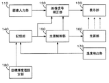
図1は、本発明を適用できる画像表示装置の一例を含む液晶ディスプレイの構成を示すブロック図である。図1において、本実施形態は、画像入力部110、画像信号補正部120、表示部130、記憶部140、光源制御部150、光源部160、温度検出部170、及び目標輝度値設定部180から構成される。
Example 1
Hereinafter, exemplary embodiments of the present invention will be described in detail with reference to the accompanying drawings.
FIG. 1 is a block diagram showing a configuration of a liquid crystal display including an example of an image display device to which the present invention can be applied. In FIG. 1, this embodiment includes an
画像入力部110は、例えば、HDMI(High-Definition Multimedia Interface)、DVI(Digital Visual Interface)、DisplayPortなどの画像入力端子等から画像信号
が入力される。画像入力部110は、パーソナルコンピュータやビデオプレイヤー、不図示の画像記憶部などの画像出力機器と接続される。画像入力部110は、画像出力機器が出力する画像信号を受信し、受信した画像信号を画像信号補正部120に出力する。
The
画像信号補正部120は、後述する記憶部140が出力する目標輝度値、及び、光源制御部150が出力する光源輝度値に応じて画像入力部110から入力される画像信号に対し輝度値を補正する画像処理を行う(画像処理手段)。画像信号補正部120は、画像信号に対し、各画素の画素値にゲイン値を乗算することにより輝度値の補正をする。ゲイン値は、0から1の範囲の値であり、ゲイン値が1の場合、画像信号の各画素値に1を乗算する(1倍する)ので、画像信号の輝度値は補正前後で変わらない。
The image
ゲイン値が小さくなるほど、画像信号の各画素値が小さくなるので、光源部160の発光量が同一の条件では、補正後の画像信号の方が補正前の画像信号より暗くなる。すなわち、ゲイン値が1以外の場合は、画像信号補正部120は、入力される画像信号に対し輝度値を低下させる補正を行う。
As the gain value decreases, each pixel value of the image signal decreases, so that under the same light emission amount of the
ゲイン値が小さいほど、画像信号補正部120による画像信号の輝度値を低下させる補正量が大きいことを示す。画像信号補正部120は、例えば、後述する表示部130の表示特性などに応じて画像信号の輝度値、色やガンマなどを補正する画像処理部(不図示)の一部として構成されていても良い。画像信号補正部120は、補正を施した画像信号を表示部130に出力する。
The smaller the gain value, the larger the correction amount by which the luminance value of the image signal by the image
表示部130は、例えば、液晶パネルにより構成され、画像信号補正部120から入力される画像信号に従って、光源部160から入射する光の透過率を画素毎に変更する(表示パネル)。光源部160が表示部130の背面から光を照射し、表示部130の液晶パネルが画像信号補正部120から入力される画像信号に応じて制御されることにより、表示部130に画像が表示される。
The
記憶部140は、不揮発メモリなどの書き換え可能な記憶媒体であり、目標輝度値、及
び、設定時温度を記憶する(記憶手段)。目標輝度値は、表示部130に表示された画像の輝度(表示輝度)の目標値である。表示輝度値が大きいほど表示部130に画像が明るく表示され、表示輝度値が小さいほど表示部130に画像が暗く表示されていることを示す。本実施形態における画像表示装置は、表示輝度値が、目標輝度値と等しくなるように動作する。
The
そのため、ユーザは、目標輝度値を任意の値に設定することにより表示輝度を調整することができる。すなわち、ユーザが目標輝度値を上げると、表示部130における画像の表示が明るくなり、ユーザが目標輝度値を下げると、表示部130における画像の表示が暗くなるように、画像表示装置は動作する。
Therefore, the user can adjust the display brightness by setting the target brightness value to an arbitrary value. That is, when the user increases the target luminance value, the image display apparatus operates so that the image display on the
設定時温度は、ユーザが目標輝度値を変更して表示輝度を調整した時に後述する温度検出部170が検出した、光源部160を構成するLED(発光素子)の周囲温度である(設定時温度)。記憶部140は、目標輝度値を画像信号補正部120と光源制御部150に出力し、設定時温度を光源制御部150に出力する。
The setting temperature is the ambient temperature of the LEDs (light emitting elements) constituting the
光源制御部150は、記憶部140から目標輝度値と設定時温度、温度検出部170から検出温度を受け取り、光源部160の発光量を調節することにより、光源輝度値を制御する(バックライト制御手段)。光源輝度値は、光源部160の輝度値であり、画像信号補正部120がゲイン値を1とした場合、すなわち画像信号に対し輝度値を変化させる補正を行わない場合の、表示部130の表示輝度値に相当する。
The light
この場合の表示部130の表示輝度は、白色画像を表示させた場合の表示輝度とする。光源制御部150は、光源輝度値を画像信号補正部120に出力する。画像信号補正部120がゲイン値を1より小さい値とした場合、すなわち画像信号に対し輝度値を低下させる補正を行う場合の表示部130の表示輝度値は、光源輝度値よりも低くなる。
The display brightness of the
光源制御部150は、光源部160にパルス信号であるPWM(Pulse Wide Modulation)信号を出力し、PWM信号のデューティ比を変えることで光源部160の発光量を制
御する。光源制御部150による光源部160の制御の詳細は後述する。なお、光源制御部150は、例えば、マイクロコンピュータの一部として構成されていても良い。
The
光源部160は、複数個のLEDから構成された面状の発光体であり、白色光を表示部130の背面から照射する(バックライト)。光源部160の発光量は、光源制御部150が出力するPWM信号によって制御可能である。
The
光源部160を構成する各LEDは、光源制御部150が出力するPWM信号がHighの期間は点灯し、Lowの期間は消灯する。そのため、光源制御部150が出力するPWM信号のデューティ比が増加するとPWM信号のHigh期間が長くなり、LEDの点灯期間も長くなるので光源部160の発光量が増加する。
Each LED constituting the
PWM信号のデューティ比が減少するとPWM信号のHigh期間が短くなり、LEDの点灯期間も短くなるので光源部160の発光量が減少する。光源部160を構成するLEDは、白色LEDでも良いし、赤色LED、緑色LED、青色LEDなど他の複数の色のLEDの組み合わせであって、各色を混色して白色を発光するようにしても良い。
When the duty ratio of the PWM signal is decreased, the High period of the PWM signal is shortened and the lighting period of the LED is also shortened, so that the light emission amount of the
温度検出部170は、温度センサとA/Dコンバータから構成される。温度センサは、光源部160を構成するLEDの周囲温度を検出し、検出結果であるアナログ信号をA/Dコンバータに出力する。A/Dコンバータは、温度センサの検出信号をデジタル値に変換する。温度検出部170は、A/Dコンバータによって変換したデジタル値を摂氏温度
に換算し、換算した温度を検出温度として記憶部140、及び、光源制御部150に出力する(温度検出手段)。
The
目標輝度値設定部180は、ユーザから目標輝度値の入力を受け付け、記憶部140に渡す(設定手段)。目標輝度値設定部180は、例えば、画像表示装置の本体に設けられる操作ボタンやリモコン、或いは、画像表示装置と接続されたPCなどでもよい。
The target luminance
(動作例の説明)
続いて、ユーザが目標輝度値を設定する際の画像表示装置の動作例を説明する。表示輝度は、記憶部140が保持する目標輝度値を変更することにより調整可能である。目標輝度値の変更は、目標輝度値設定部180により行われる。例えば、ユーザは、画面を見ながら画像表示装置に備えられたボタン等を押下することにより、目標輝度値を変更する指示を画像表示装置に入力することができる。
(Explanation of operation example)
Next, an operation example of the image display apparatus when the user sets the target luminance value will be described. The display brightness can be adjusted by changing the target brightness value held by the
また、ユーザは、画像表示装置と接続されたコンピュータを操作することにより、目標輝度値を変更する指示を入力することもできる。その場合、入力された指示に基づきコンピュータが通信線を介して記憶部140に保持されている目標輝度値を変更する指示を画像表示装置に入力することにより、画像表示装置の表示輝度が調整される。
The user can also input an instruction to change the target luminance value by operating a computer connected to the image display device. In that case, the display brightness of the image display device is adjusted by inputting, to the image display device, an instruction to change the target brightness value held in the
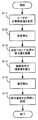
図2は、ユーザが目標輝度値を設定する際の本実施形態における画像表示装置の動作を示すフローチャートである。 FIG. 2 is a flowchart showing the operation of the image display apparatus in the present embodiment when the user sets the target luminance value.
図2のステップS11において、ユーザが目標輝度値を変更すると、目標輝度値設定部180は変更後の目標輝度値を記憶部140に送信し、記憶部140は変更後の目標輝度値を記憶する。
When the user changes the target luminance value in step S11 of FIG. 2, the target luminance
ステップS12において、温度検出部170は、光源部160を構成するLEDの周囲温度を検出する。
In step S <b> 12, the
ステップS13において、光源制御部150は、記憶部140に記憶している目標輝度値と、ステップS12において温度検出部170が検出したLEDの周囲温度(検出温度)に応じて、光源部160の発光量を調整し、光源輝度値を制御する。
In step S13, the light
図3に、検出温度と光源輝度値の関係を示す。図3において、横軸は温度検出部170の検出温度を表し、縦軸は、光源輝度値を表す。温度閾値TH(所定の閾値)は、予め設計時に定めた固定値であり、例えば、画像表示装置の推奨環境温度の上限温度で画像表示装置を使用した際に温度検出部170が検出したLEDの周囲温度とすることができる。
FIG. 3 shows the relationship between the detected temperature and the light source luminance value. In FIG. 3, the horizontal axis represents the detected temperature of the
検出温度が温度閾値TH以上の場合、光源制御部150は、光源輝度値と記憶部140が出力する目標輝度値とが一致するように、光源部160の発光量を調節する。検出温度が温度閾値THよりも低い場合、光源制御部150は、光源輝度値が目標輝度値よりも輝度増加量ΔBLだけ高くなるように光源部160の発光量を調節する。
When the detected temperature is equal to or higher than the temperature threshold TH, the light
すなわち、光源制御部150は、光源輝度値の制御における初期値を、検出温度が温度閾値TH以上の場合は、目標輝度値と等しい値に設定し、検出温度が温度閾値THより低い場合は、目標輝度値より高い値に設定する(初期値設定手段)。
That is, the light
ここで輝度増加量ΔBLについて説明する。画像表示装置が設置された環境温度が上昇するとLEDの周囲温度が上昇し、環境温度が下降するとLEDの周囲温度が下降する。一方、LEDの周囲温度は、光源部160の発光量とも関係がある。
Here, the luminance increase amount ΔBL will be described. When the environmental temperature at which the image display device is installed increases, the ambient temperature of the LED increases, and when the environmental temperature decreases, the ambient temperature of the LED decreases. On the other hand, the ambient temperature of the LED is also related to the light emission amount of the
光源部160の発光量が上がると、光源の発熱量の増加により、LEDの周囲温度は、光源部160の発光量が上がる前と比較して上昇する。光源部160の発光量が下がると、光源部160の発熱量の減少により、LEDの周囲温度は、光源部160の発光量が下がる前と比較して下降する。
When the light emission amount of the
従って、環境温度が上昇しても、光源部160の発光量を下げて光源の発熱量を減少させれば、LEDの周囲温度の上昇を抑制することが可能である。しかし、LEDの周囲温度の上昇を抑制すべく光源部160の発光量を下げると、光源輝度値が低下するので、表示輝度が低下して目標輝度値を下回ってしまう。
Therefore, even if the environmental temperature rises, if the light emission amount of the
これを回避するため、ユーザによる目標輝度値の設定時に、予め光源輝度値の初期値を目標輝度値よりも高くしておく。つまり、環境温度が上昇した際にLEDの周囲温度の上昇を抑制すべく光源部160の発光量を下げても、光源輝度値が目標輝度値を下回らないようにすることができるだけのマージンを持たせておく。このマージンが輝度増加量ΔBL(光源輝度値の初期値の目標輝度値に対する差分)である。
In order to avoid this, the initial value of the light source luminance value is set higher than the target luminance value in advance when the user sets the target luminance value. That is, there is enough margin to prevent the light source luminance value from falling below the target luminance value even if the light emission amount of the
目標輝度値の設定時に温度検出部170が検出した温度が低いほど、目標輝度値を設定した後に環境温度の上昇などに起因してLEDの周囲温度が設定時温度より上昇する可能性が高い。その場合、LEDの発光スペクトルが目標輝度値の設定時からずれることになり、表示色が変化する可能性がある。
The lower the temperature detected by the
目標輝度値を設定した後にLEDの周囲温度の上昇を検出した場合に、表示輝度の低下を抑えつつ光源部160の発光量を下げることができるように、設定時温度が低い場合は、輝度増加量ΔBLを大きな値としておく。
When an increase in ambient temperature of the LED is detected after setting the target luminance value, the luminance increases when the set temperature is low so that the light emission amount of the
反対に、目標輝度値の設定時に温度検出部170が検出した温度が十分に高ければ、目標輝度値の設定後にLEDの周囲温度がそれ以上上昇することは少ないため、輝度増加量ΔBLは小さな値とする。
On the other hand, if the temperature detected by the
つまり、輝度増加量ΔBLは、目標輝度値の設定後に、LEDの周囲温度の上昇を抑制するために光源部160の発光量を減らして光源輝度値を下げた場合に、表示輝度の低下を抑制できるように予め設ける光源輝度値の余裕分である。光源輝度値が目標輝度値より高い場合は、画像信号補正部120がゲイン値を下げる(輝度値を低下させる補正の補正量を大きくする)。
That is, the luminance increase amount ΔBL suppresses a decrease in display luminance when the light source luminance value is decreased by reducing the light emission amount of the
これにより、光源輝度値の目標輝度値に対する超過分(差分)が相殺され、表示輝度値が目標輝度値に一致するようにできる。しかしながら、光源輝度値が目標輝度値より低くなってしまうと、ゲイン値を最大(1)にしても、表示輝度値は目標輝度値を下回ってしまう。LEDの周囲温度の上昇を抑制すべく光源輝度値を低下させる制御を行った場合に、光源輝度値が目標輝度値より低くなってしまうことを回避できるように、予め光源輝度値を目標輝度値より輝度増加量ΔBLだけ高くしておく。 Thereby, the excess (difference) of the light source luminance value with respect to the target luminance value is canceled, and the display luminance value can be made to match the target luminance value. However, if the light source luminance value becomes lower than the target luminance value, the display luminance value will be lower than the target luminance value even if the gain value is maximized (1). In order to prevent the light source luminance value from becoming lower than the target luminance value when control is performed to reduce the light source luminance value so as to suppress an increase in the ambient temperature of the LED, the light source luminance value is set in advance to the target luminance value. The luminance is increased by the amount of increase ΔBL.
光源制御部150は、光源部160に出力するPWM信号のディーティ比を変更して光源部160の発光量を制御し、光源部160の発光量に応じた光源輝度値を画像信号補正部120に出力する。
The light
設定時温度が温度閾値THより低い場合には、光源輝度値が目標輝度値より高い値に設定されるため、この段階では表示輝度値が目標輝度値より高いことになる。設定時温度が温度閾値TH以上である場合には、光源輝度値が目標輝度値と等しい値に設定されるため
、この段階で表示輝度値は目標輝度値に一致する。
When the set temperature is lower than the temperature threshold TH, the light source luminance value is set to a value higher than the target luminance value, and therefore the display luminance value is higher than the target luminance value at this stage. When the set temperature is equal to or higher than the temperature threshold TH, the light source luminance value is set to a value equal to the target luminance value, and at this stage, the display luminance value matches the target luminance value.
ステップS14において、画像信号補正部120は、表示輝度が目標輝度値と一致するように画像信号の輝度値を補正する。ステップS13において、検出温度がTH以上の場合は、光源制御部150が出力する光源輝度値が目標輝度値と一致することから画像信号補正部120はゲイン値を1にする。すなわち、画像信号補正部120は、画像信号の輝度値を低下させる補正は行わない。
In step S14, the image
ステップS13において、検出温度がTHよりも低い場合は、光源制御部150が出力する光源輝度値は目標輝度値より輝度増加量ΔBLだけ高いことから、画像信号補正部120は画像信号の輝度値を下げる補正を行う。この場合、画像信号補正部120は、例えば、目標輝度値がL、光源輝度値がBLの場合、ゲイン値GをL/BLとする。画像信号補正部120は、算出したゲイン値Gを画像信号の各画素に乗算し、画像信号の輝度値を補正する。
In step S13, when the detected temperature is lower than TH, the light source luminance value output from the light
以上のステップS14の処理により、表示輝度は目標輝度値と一致する。このように、設定時温度に応じて決定された光源輝度値に応じて、表示輝度値が目標輝度値と等しくなるように、画像信号の輝度値を低下させる補正量の初期値を設定する画像信号補正部120は、本発明の初期値設定手段として機能している。
Through the processing in step S14 described above, the display luminance matches the target luminance value. In this manner, an image for setting an initial value of a correction amount for reducing the luminance value of the image signal so that the display luminance value becomes equal to the target luminance value according to the light source luminance value determined according to the set temperature. The
ステップS15において、温度検出部170は、光源部160を構成するLEDの周囲温度を検出する。
In step S <b> 15, the
ステップS16において、記憶部140は、ステップS15において温度検出部170が検出した検出温度を設定時温度として記憶する。
In step S16, the
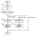
続いて、ユーザが目標輝度値を設定した後の画像表示装置の動作例を説明する。図4は、画像表示装置の定常処理の動作内容を示すフローチャートである。画像表示装置は、ユーザが目標輝度値を設定した後、図4に示す処理を周期的に実行する。 Subsequently, an operation example of the image display device after the user sets the target luminance value will be described. FIG. 4 is a flowchart showing the operation content of the steady process of the image display apparatus. After the user sets the target luminance value, the image display device periodically executes the process shown in FIG.
ステップS21において、温度検出部170は光源部160を構成するLEDの周囲温度を検出する。
In step S <b> 21, the
ステップS22において、光源制御部150は、ステップS21にて温度検出部170が検出した温度と、目標輝度値の設定時に記憶部140に記憶した設定時温度と、を比較する。比較の結果、検出温度が設定時温度よりも高い場合、光源制御部150は、ステップS23に進み、検出温度が設定時温度より低い場合、光源制御部150は、ステップS25へ進む。また、検出温度が設定時温度と等しい場合、光源制御部150は、図4に示すフローチャートの処理を終了する。
In step S22, the light
検出温度が設定時温度よりも高い場合、光源制御部150は、ステップS23において、LEDの周囲温度を下げるために、光源輝度値を低下させる制御を行う。具体的には、光源制御部150は、光源部160に出力するPWM信号のディーティ比を変更することで、光源部160の発光量を下げる。このとき、光源制御部150は、光源輝度値が目標輝度値を下回らない範囲内で光源部160の発光量を下げる。また、光源制御部150は、変更した光源輝度値を画像信号補正部120に出力する。
If the detected temperature is higher than the set temperature, the light
ステップS24において、画像信号補正部120は、ステップS23において、光源制御部150が変更した光源輝度値を元にゲイン値を算出する。画像信号補正部120は、例えば、目標輝度値がL1、ステップS23にて光源制御部150が変更した後の光源輝
度値がBL1の場合、ゲイン値G1をL1/BL1とする。画像信号補正部120は、算出したゲイン値G1を画像信号の各画素に乗算し、画像信号の輝度値を補正する。その結果、表示輝度は、目標輝度値と一致する。
In step S24, the image
一方、検出温度が設定時温度よりも低い場合、光源制御部150は、ステップS25において、LEDの周囲温度を上げるために、光源輝度値を増加させる制御を行う。具体的には、光源制御部150は、光源部160に出力するPWM信号のディーティ比を変更することで、光源部160の発光量を上げる。また、光源制御部150は、変更した光源輝度値を画像信号補正部120に出力する。
On the other hand, when the detected temperature is lower than the preset temperature, the light
ステップS26において、画像信号補正部120は、ステップS25において、光源制御部150が変更した光源輝度値を元にゲイン値を算出する。画像信号補正部120は、例えば、目標輝度値がL2、ステップS25にて光源制御部150が変更した後の光源輝度値がBL2の場合、ゲイン値G2をL2/BL2とする。画像信号補正部120は、算出したゲイン値G2を画像信号の各画素に乗算し、画像信号の輝度値を補正する。その結果、表示輝度は、目標輝度値と一致する。
In step S26, the image
以上のように図4に示すフローチャートの制御が実行されることで、検出温度が設定時温度よりも高いときには、光源部160の発光量が下げられるので、光源の発熱量が減少し、LEDの周囲温度が下がる。また、検出温度が設定時温度よりも低いときには、光源部160の発光量が上げられるので、光源の発熱量が増加し、LEDの周囲温度が上がる。
By executing the control of the flowchart shown in FIG. 4 as described above, when the detected temperature is higher than the set temperature, the light emission amount of the
図4に示すフローチャートの処理を周期的に実行することにより、検出温度を設定時温度に近付けるように光源輝度値が制御される。したがって、ユーザが目標輝度値を設定した後、環境温度の変化などのLEDの周囲温度に対する外乱があった場合でも、それに起因してLEDの周囲温度が設定時温度から大きく変化することが抑制される。よって、ユーザが目標輝度値を設定した後、LEDの発光スペクトルが変化することが抑制され、表示色の変化が抑制される。 By periodically executing the process of the flowchart shown in FIG. 4, the light source luminance value is controlled so that the detected temperature approaches the set temperature. Therefore, even if there is a disturbance with respect to the ambient temperature of the LED such as a change in the environmental temperature after the user sets the target brightness value, the ambient temperature of the LED is prevented from greatly changing from the set temperature due to the disturbance. The Therefore, after the user sets the target luminance value, the change in the emission spectrum of the LED is suppressed, and the change in display color is suppressed.
上記の制御では、検出温度が設定時温度より上昇すると光源部160の発光量が下げられるが、画像信号補正部120がゲイン値を1に近付く方向に上昇させて画像信号の輝度値を低下させる補正量を減らすため、結果として表示輝度の低下を招くことを抑制できる。
In the above control, when the detected temperature rises above the set temperature, the light emission amount of the
ユーザによる目標輝度値の設定時に、設定時温度が温度閾値THより低い場合は、図2に示すフローチャートにより、光源輝度値の初期値は目標輝度値よりも明るく設定されている。従って、図4のフローチャートにより光源部160の発光量が下げられても、ゲイン値の調整により、表示輝度が目標輝度値を下回らないようにすることができる。
If the set temperature is lower than the temperature threshold TH when the user sets the target luminance value, the initial value of the light source luminance value is set to be brighter than the target luminance value according to the flowchart shown in FIG. Therefore, even if the light emission amount of the
また、検出温度が設定時温度より低くなったときは、光源部160の発光量が上げられるが、画像信号補正部120が光源部160の発光量の上昇による光源輝度値の上昇を相殺するようにゲイン値を低下させる。よって画像信号の輝度値を低下させる補正の補正量が大きくなるため、結果として表示輝度は上昇しない。
Further, when the detected temperature becomes lower than the set temperature, the light emission amount of the
続いて、ユーザが目標輝度値を設定した後、一旦、画像表示装置の電源をオフにし、その後、電源を投入した時の画像表示装置の動作を説明する。 Subsequently, after the user sets the target luminance value, the operation of the image display apparatus when the power of the image display apparatus is once turned off and then turned on will be described.
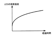
画像表示装置の電源が投入されると、画像表示装置の内部の電源部分などが発熱し始める。また、光源部160のLEDが点灯するので、光源部160が発熱し始める。図5は
、従来の画像表示装置において、電源をオフの状態から電源を投入した後のLEDの周囲温度の変化の一例を示す。
When the power of the image display device is turned on, the power supply portion inside the image display device starts to generate heat. Moreover, since the LED of the
図5において、横軸は、電源を投入にしてからの経過時間であり、縦軸は、LEDの周囲温度である。電源を投入にしてからディスプレイ内部の発熱が始まるため、LEDの周囲温度は時間が経過するごとに少しずつ上昇する。LEDの周囲温度が収束するまでの間は、LEDの温度特性により表示色が変化してしまう。また、LEDの周囲温度の収束値が、ユーザが目標輝度値の設定を行った時のLEDの周囲温度(設定時温度)と等しくない場合、目標輝度値を設定したときに対して表示色がずれてしまう。 In FIG. 5, the horizontal axis represents the elapsed time since the power was turned on, and the vertical axis represents the ambient temperature of the LED. Since the heat generation inside the display starts after the power is turned on, the ambient temperature of the LED gradually increases as time elapses. Until the ambient temperature of the LED converges, the display color changes due to the temperature characteristics of the LED. In addition, when the convergence value of the ambient temperature of the LED is not equal to the ambient temperature of the LED when the user sets the target brightness value (setting temperature), the display color is different from when the target brightness value is set. It will shift.
本実施形態における画像表示装置では、電源を投入した直後から周期的に(一定時間毎に)図4に示すフローチャートの処理が実行される。 In the image display apparatus according to the present embodiment, the process of the flowchart shown in FIG. 4 is executed periodically (at regular intervals) immediately after the power is turned on.
図4のステップS21において、温度検出部170は光源部160を構成するLEDの周囲温度を検出する。
In step S <b> 21 of FIG. 4, the
ステップS22において、光源制御部150は、ステップS21にて温度検出部170が検出した温度と、目標輝度値の設定時に記憶部140に記憶した設定時温度と、を比較する。比較の結果、現在の検出温度が設定時温度よりも高い場合、光源制御部150は、ステップS23に進み、検出温度が設定時温度より低い場合、光源制御部150は、ステップS25へ進む。また、検出温度が設定時温度と等しい場合、光源制御部150は、図4に示すフローチャートの処理を終了する。
In step S22, the light
電源を投入した直後は、ディスプレイの内部が徐々に発熱し始めた途中であるため、LEDの周囲温度もまだ低い状態にある。したがって、検出温度は設定時温度よりも低いため、光源制御部150は、ステップS25に進む。
Immediately after the power is turned on, the inside of the display is in the middle of gradually starting to generate heat, so the ambient temperature of the LED is still low. Accordingly, since the detected temperature is lower than the set temperature, the light
ステップS25において、光源制御部150は、LEDの周囲温度を上昇させて設定時温度に近付けるために、光源輝度値を増加させる制御を行う。具体的には、光源制御部150は、光源部160に出力するPWM信号のディーティ比を変更し、光源部160の発光量を上げる。また、光源制御部150は、光源部160の発光量を上げた後の光源輝度値を画像信号補正部120に出力する。
In step S <b> 25, the light
ステップS26において、画像信号補正部120は、ステップS25において、光源制御部150が変更した光源輝度値を元にゲイン値を算出する。画像信号補正部120は、例えば、目標輝度値がL3、ステップS25にて光源制御部150が変更した後の光源輝度値がBL3の場合、ゲイン値G3をL3/BL3とする。画像信号補正部120は、算出したゲイン値G3を画像信号の各画素に乗算し、画像信号の輝度値を補正する。ここでは、光源輝度値が上げられるので、ゲイン値が下げられる。その結果、光源輝度値の上昇がゲイン値の低下により相殺されて、表示輝度は、目標輝度値と一致する。
In step S26, the image
図6に、本実施形態の画像表示装置において、電源がオフの状態から電源を投入した後、上記の制御が行われた場合の、光源部160を構成するLEDの周囲温度の変化を示す。図6において、横軸は、電源を投入にしてからの経過時間であり、縦軸は、温度検出部170が検出するLEDの周囲温度である。
FIG. 6 shows a change in ambient temperature of the LEDs constituting the
電源が投入された直後は、検出温度が設定時温度よりも低いため、図4に示すフローチャートの処理が実行されることにより、画像表示装置は光源の発光量を上げるように動作する。したがって、光源の発熱量が増加することになり、図5に示す従来の画像表示装置における電源投入後のLEDの周囲温度の変化と比べて、LEDの周囲温度が速やかに上
昇し、設定時温度に近づくまでの時間が短縮される。
そのため、LEDの周囲温度の設定時温度との相違に起因する表示色のずれが発生する期間が従来の画像表示装置よりも短くなる。
Immediately after the power is turned on, since the detected temperature is lower than the set temperature, the processing of the flowchart shown in FIG. 4 is executed, so that the image display device operates to increase the light emission amount of the light source. Therefore, the amount of heat generated by the light source is increased, and the ambient temperature of the LED rapidly increases compared to the change in ambient temperature of the LED after power-on in the conventional image display device shown in FIG. Time to approach is shortened.
Therefore, the period during which the display color shift occurs due to the difference between the ambient temperature of the LED and the set temperature is shorter than that of the conventional image display device.
また、本実施例の画像表示装置では、図4に示す処理により光源輝度値が制御されることで、図6に示すように、LEDの周囲温度が設定時温度に収束する。従って、LEDの発光スペクトルが、ユーザが目標輝度値を設定した時のLEDの発光スペクトルから乖離することが抑制され、表示色が安定する。 In the image display apparatus according to the present embodiment, the light source luminance value is controlled by the process shown in FIG. 4, so that the ambient temperature of the LED converges to the set temperature as shown in FIG. 6. Therefore, the LED emission spectrum is prevented from deviating from the LED emission spectrum when the user sets the target luminance value, and the display color is stabilized.
温度検出部170が複数存在する場合、画面の輝度値にムラがないように調整した時に、個々の温度検出部170において図2のステップS12以下のフローの処理を行う。画面の輝度値にムラがない状態での検出温度を、図4のフローにおける設定時温度として記憶部140に記憶し、個々の温度検出部170にて上記の制御を行うことで、画面の輝度ムラを抑えつつ、環境温度が変化した場合でも表示色の変動を低減することができる。
When there are a plurality of
以上説明したように本実施形態によれば、画像表示装置の設置された環境温度が変化する場合においても、表示色の変動を低減することができる。また、LEDの周囲温度の制御をLEDの発光量の調整により行うので、ファン等の冷却装置を必要とせず、画像表示装置本体の薄型化に有利である。 As described above, according to this embodiment, even when the environmental temperature in which the image display device is installed changes, the variation in display color can be reduced. Further, since the ambient temperature of the LED is controlled by adjusting the light emission amount of the LED, a cooling device such as a fan is not required, which is advantageous for making the image display device main body thin.
また、本実施例の画像表示装置は、電源投入後、速やかに表示色が目標輝度値調整時の表示色に近付き、且つ、その表示色で安定して表示が行われるので、正確な色の表示が要求される用途に好適である。
また、LEDの周囲温度は、ユーザが目標輝度値を設定したときの温度である設定時温度と近づくように動作するため、ユーザが目標輝度値を設定したときの表示色を保つことができる。
In the image display apparatus of this embodiment, the display color approaches the display color at the time of target luminance value adjustment immediately after the power is turned on, and stable display is performed with the display color. Suitable for applications that require display.
Further, since the ambient temperature of the LED operates so as to approach the set temperature which is the temperature when the user sets the target brightness value, the display color when the user sets the target brightness value can be maintained.
120 画像信号補正部、130 表示部、150 光源制御部、160 光源部、170 温度検出部、180 目標輝度値設定部 120 image signal correction unit, 130 display unit, 150 light source control unit, 160 light source unit, 170 temperature detection unit, 180 target luminance value setting unit
Claims (7)
入力する画像信号に応じて前記バックライトから入射する光の透過率を画素毎に変更することで画像を表示する表示パネルと、
前記発光素子の発光量を調節することによりバックライトの輝度値である光源輝度値を制御するバックライト制御手段と、
前記表示パネルに入力される画像信号に対し輝度値の補正を行う画像処理手段と、
前記バックライトの発光素子の周囲の温度を検出する温度検出手段と、
前記表示パネルの表示輝度の目標値である目標輝度値を設定する設定手段と、
前記設定手段により目標輝度値が設定された時に前記温度検出手段により検出される前記発光素子の周囲の温度である設定時温度が、所定の閾値より低い場合、前記バックライト制御手段により制御される光源輝度値の初期値を目標輝度値より高い値に設定するとともに、当該光源輝度値の初期値の目標輝度値に対する差分に応じて、表示輝度が目標輝度値と等しくなるように、前記画像処理手段による画像信号の輝度値を低下させる補正量の初期値を設定する初期値設定手段と、
を有し、
前記設定手段により目標輝度値が設定された後、
前記バックライト制御手段は、光源輝度値が目標輝度値を下回らない範囲内で前記発光素子の発光量を調節することにより、前記温度検出手段により検出される前記発光素子の周囲の温度を前記設定時温度に近付けるように光源輝度値を制御し、
前記画像処理手段は、前記バックライト制御手段により制御される光源輝度値の目標輝度値に対する差分に応じて、表示輝度が目標輝度値と等しくなるように、画像信号の輝度値を低下させる補正量を調節する、
ことを特徴とする画像表示装置。 A backlight having one or more light emitting elements;
A display panel for displaying an image by changing the transmittance of light incident from the backlight for each pixel according to an input image signal;
Backlight control means for controlling a light source luminance value, which is a luminance value of a backlight, by adjusting a light emission amount of the light emitting element;
Image processing means for correcting a luminance value for an image signal input to the display panel;
Temperature detecting means for detecting the temperature around the light emitting element of the backlight; and
Setting means for setting a target luminance value which is a target value of the display luminance of the display panel;
When the set temperature, which is the ambient temperature of the light emitting element detected by the temperature detecting means when the target brightness value is set by the setting means, is lower than a predetermined threshold, it is controlled by the backlight control means. The image processing is performed such that the initial value of the light source luminance value is set to a value higher than the target luminance value, and the display luminance is equal to the target luminance value according to a difference between the initial value of the light source luminance value and the target luminance value. Initial value setting means for setting an initial value of a correction amount for reducing the luminance value of the image signal by the means;
Have
After the target brightness value is set by the setting means,
The backlight control unit adjusts the light emission amount of the light emitting element within a range where the light source luminance value does not fall below the target luminance value, thereby setting the temperature around the light emitting element detected by the temperature detecting unit. Control the light source brightness value so that it approaches the hourly temperature,
The image processing means is a correction amount for reducing the brightness value of the image signal so that the display brightness becomes equal to the target brightness value in accordance with a difference between the light source brightness value controlled by the backlight control means and the target brightness value. Adjust the
An image display device characterized by that.
前記温度検出手段により検出される前記発光素子の周囲の温度が前記設定時温度より高くなった場合、発光素子の発光量を低下させることにより光源輝度値を低下させ、
前記温度検出手段により検出される前記発光素子の周囲の温度が前記設定時温度より低くなった場合、発光素子の発光量を増加させることにより光源輝度値を増加させ、
前記画像処理手段は、
前記バックライト制御手段が光源輝度値を低下させた場合、画像信号の輝度値を低下させる補正量を小さくし、
前記バックライト制御手段が光源輝度値を増加させた場合、画像信号の輝度値を低下させる補正量を大きくする
ことを特徴とする請求項1に記載の画像表示装置。 The backlight control means includes
When the ambient temperature of the light emitting element detected by the temperature detecting means becomes higher than the set temperature, the light source luminance value is reduced by reducing the light emission amount of the light emitting element,
When the ambient temperature of the light emitting element detected by the temperature detecting means is lower than the set temperature, the light source luminance value is increased by increasing the light emission amount of the light emitting element,
The image processing means includes
When the backlight control means decreases the light source luminance value, the correction amount for decreasing the luminance value of the image signal is reduced,
The image display apparatus according to claim 1, wherein when the backlight control unit increases the light source luminance value, the correction amount for decreasing the luminance value of the image signal is increased.
画像表示装置に電源が投入された直後、
前記バックライト制御手段は、光源輝度値の初期値として前記記憶手段から読み出した光源輝度値の初期値を用い、前記温度検出手段により検出される前記発光素子の周囲の温度を前記記憶手段から読み出した設定時温度に近付けるように光源輝度値を制御し、
前記画像処理手段は、画像信号の輝度値を低下させる補正量の初期値として前記記憶手段から読み出した画像信号の輝度値を低下させる補正量の初期値を用い、前記バックラ
イト制御手段により制御される光源輝度値の前記記憶手段から読み出した目標輝度値に対する差分に応じて、表示輝度が当該目標輝度値と等しくなるように、画像信号の輝度値を低下させる補正量を調節する、
ことを特徴とする請求項1から3のいずれか1項に記載の画像表示装置。 Storage means for storing a target luminance value, a set temperature, an initial value of the light source luminance value, and an initial value of a correction amount for reducing the luminance value of the image signal;
Immediately after the image display device is turned on,
The backlight control means uses the initial value of the light source luminance value read from the storage means as the initial value of the light source luminance value, and reads the ambient temperature of the light emitting element detected by the temperature detection means from the storage means. Control the light source brightness value to approach the set temperature
The image processing means uses the initial value of the correction amount for reducing the luminance value of the image signal read from the storage means as the initial value of the correction amount for reducing the luminance value of the image signal, and is controlled by the backlight control means. Adjusting the correction amount for reducing the luminance value of the image signal so that the display luminance is equal to the target luminance value according to the difference of the light source luminance value with respect to the target luminance value read from the storage unit.
The image display device according to claim 1, wherein the image display device is an image display device.
入力する画像信号に応じて前記バックライトから入射する光の透過率を画素毎に変更することで画像を表示する表示パネルと、
を有する画像表示装置の制御方法であって、
前記発光素子の発光量を調節することによりバックライトの輝度値である光源輝度値を制御するバックライト制御工程と、
前記表示パネルに入力される画像信号に対し輝度値の補正を行う画像処理工程と、
前記バックライトの発光素子の周囲の温度を検出する温度検出工程と、
前記表示パネルの表示輝度の目標値である目標輝度値を設定する設定工程と、
前記設定工程により目標輝度値が設定された時に前記温度検出工程により検出される前記発光素子の周囲の温度である設定時温度が、所定の閾値より低い場合、前記バックライト制御工程により制御される光源輝度値の初期値を目標輝度値より高い値に設定するとともに、当該光源輝度値の初期値の目標輝度値に対する差分に応じて、表示輝度が目標輝度値と等しくなるように、前記画像処理工程による画像信号の輝度値を低下させる補正量の初期値を設定する初期値設定工程と、
を有し、
前記設定工程により目標輝度値が設定された後、
前記バックライト制御工程は、光源輝度値が目標輝度値を下回らない範囲内で前記発光素子の発光量を調節することにより、前記温度検出工程により検出される前記発光素子の周囲の温度を前記設定時温度に近付けるように光源輝度値を制御し、
前記画像処理工程は、前記バックライト制御工程により制御される光源輝度値の目標輝度値に対する差分に応じて、表示輝度が目標輝度値と等しくなるように、画像信号の輝度値を低下させる補正量を調節する、
ことを特徴とする画像表示装置の制御方法。 A backlight having one or more light emitting elements;
A display panel for displaying an image by changing the transmittance of light incident from the backlight for each pixel according to an input image signal;
A method for controlling an image display device comprising:
A backlight control step of controlling a light source luminance value, which is a luminance value of a backlight, by adjusting a light emission amount of the light emitting element;
An image processing step of correcting a luminance value for an image signal input to the display panel;
A temperature detection step of detecting a temperature around the light emitting element of the backlight; and
A setting step of setting a target luminance value that is a target value of the display luminance of the display panel;
When the set temperature, which is the ambient temperature of the light emitting element detected by the temperature detecting step when the target luminance value is set by the setting step, is lower than a predetermined threshold value, it is controlled by the backlight control step. The image processing is performed such that the initial value of the light source luminance value is set to a value higher than the target luminance value, and the display luminance is equal to the target luminance value according to a difference between the initial value of the light source luminance value and the target luminance value. An initial value setting step for setting an initial value of a correction amount for reducing the luminance value of the image signal in the process;
Have
After the target brightness value is set by the setting step,
The backlight control step adjusts the light emission amount of the light emitting element within a range where the light source luminance value does not fall below the target luminance value, thereby setting the temperature around the light emitting element detected by the temperature detecting step. Control the light source brightness value so that it approaches the hourly temperature,
The image processing step includes a correction amount for reducing the luminance value of the image signal so that the display luminance becomes equal to the target luminance value according to a difference between the light source luminance value controlled by the backlight control step and the target luminance value. Adjust the
And a control method for the image display device.
Priority Applications (1)
| Application Number | Priority Date | Filing Date | Title |
|---|---|---|---|
| JP2011015251A JP2012155194A (en) | 2011-01-27 | 2011-01-27 | Image display device and its control method |
Applications Claiming Priority (1)
| Application Number | Priority Date | Filing Date | Title |
|---|---|---|---|
| JP2011015251A JP2012155194A (en) | 2011-01-27 | 2011-01-27 | Image display device and its control method |
Publications (1)
| Publication Number | Publication Date |
|---|---|
| JP2012155194A true JP2012155194A (en) | 2012-08-16 |
Family
ID=46836959
Family Applications (1)
| Application Number | Title | Priority Date | Filing Date |
|---|---|---|---|
| JP2011015251A Withdrawn JP2012155194A (en) | 2011-01-27 | 2011-01-27 | Image display device and its control method |
Country Status (1)
| Country | Link |
|---|---|
| JP (1) | JP2012155194A (en) |
-
2011
- 2011-01-27 JP JP2011015251A patent/JP2012155194A/en not_active Withdrawn
Similar Documents
| Publication | Publication Date | Title |
|---|---|---|
| US9699861B2 (en) | Light emitting apparatus and method for controlling the same | |
| JP5615226B2 (en) | LIGHT CONTROL DEVICE, ITS CONTROL METHOD, AND DISPLAY DEVICE | |
| JP5542409B2 (en) | Multi-screen display device | |
| JP4438722B2 (en) | Backlight driving device, backlight driving method, and liquid crystal display device | |
| JP2008501136A (en) | Display device having light source | |
| JP5525783B2 (en) | Light source driving device and display device including the same | |
| US9262968B2 (en) | Image display apparatus and control method thereof | |
| WO2009000182A1 (en) | Methods and apparatus for backlight calibration | |
| JP2007287422A (en) | Backlight system, liquid-crystal display device, and backlight adjusting method | |
| JP2010145773A (en) | Display device and method of controlling display device | |
| TWI488171B (en) | Image processing method of display device and display device thereof | |
| JP2007148095A (en) | Liquid crystal display device | |
| JP6138932B2 (en) | Display device, display system, video output device, and control method of display device | |
| JP2015018051A (en) | Image projection device and image display system | |
| JP2007156157A (en) | Apparatus for adjusting image quality, display apparatus, and method for adjusting image quality | |
| JP5297986B2 (en) | Light source driving method and display device using the same | |
| JP2008203769A (en) | Image display | |
| JP2010033096A (en) | Backlight driving device, backlight driving method, and liquid crystal display device | |
| JP5870173B2 (en) | LIGHT CONTROL DEVICE, ITS CONTROL METHOD, AND DISPLAY DEVICE | |
| JP4887598B2 (en) | Display device and display method | |
| JP5830530B2 (en) | Device and method for improving response time of liquid crystal display | |
| JP6288972B2 (en) | Image display apparatus and control method thereof | |
| JP2012155194A (en) | Image display device and its control method | |
| KR20090131115A (en) | Method of driving a light source, back light assembly for performing the method and display apparatus having the back light assembly | |
| JP6256997B2 (en) | Backlight device, display device, and backlight control method |
Legal Events
| Date | Code | Title | Description |
|---|---|---|---|
| A300 | Withdrawal of application because of no request for examination |
Free format text: JAPANESE INTERMEDIATE CODE: A300 Effective date: 20140401 |