JP2010145773A - Display device and method of controlling display device - Google Patents
Display device and method of controlling display device Download PDFInfo
- Publication number
- JP2010145773A JP2010145773A JP2008323366A JP2008323366A JP2010145773A JP 2010145773 A JP2010145773 A JP 2010145773A JP 2008323366 A JP2008323366 A JP 2008323366A JP 2008323366 A JP2008323366 A JP 2008323366A JP 2010145773 A JP2010145773 A JP 2010145773A
- Authority
- JP
- Japan
- Prior art keywords
- luminance
- light
- rgb
- light source
- unit
- Prior art date
- Legal status (The legal status is an assumption and is not a legal conclusion. Google has not performed a legal analysis and makes no representation as to the accuracy of the status listed.)
- Pending
Links
Images


Classifications
-
- G—PHYSICS
- G09—EDUCATION; CRYPTOGRAPHY; DISPLAY; ADVERTISING; SEALS
- G09G—ARRANGEMENTS OR CIRCUITS FOR CONTROL OF INDICATING DEVICES USING STATIC MEANS TO PRESENT VARIABLE INFORMATION
- G09G3/00—Control arrangements or circuits, of interest only in connection with visual indicators other than cathode-ray tubes
- G09G3/20—Control arrangements or circuits, of interest only in connection with visual indicators other than cathode-ray tubes for presentation of an assembly of a number of characters, e.g. a page, by composing the assembly by combination of individual elements arranged in a matrix no fixed position being assigned to or needed to be assigned to the individual characters or partial characters
- G09G3/34—Control arrangements or circuits, of interest only in connection with visual indicators other than cathode-ray tubes for presentation of an assembly of a number of characters, e.g. a page, by composing the assembly by combination of individual elements arranged in a matrix no fixed position being assigned to or needed to be assigned to the individual characters or partial characters by control of light from an independent source
- G09G3/3406—Control of illumination source
- G09G3/3413—Details of control of colour illumination sources
-
- G—PHYSICS
- G09—EDUCATION; CRYPTOGRAPHY; DISPLAY; ADVERTISING; SEALS
- G09G—ARRANGEMENTS OR CIRCUITS FOR CONTROL OF INDICATING DEVICES USING STATIC MEANS TO PRESENT VARIABLE INFORMATION
- G09G2320/00—Control of display operating conditions
- G09G2320/06—Adjustment of display parameters
- G09G2320/0626—Adjustment of display parameters for control of overall brightness
- G09G2320/064—Adjustment of display parameters for control of overall brightness by time modulation of the brightness of the illumination source
-
- G—PHYSICS
- G09—EDUCATION; CRYPTOGRAPHY; DISPLAY; ADVERTISING; SEALS
- G09G—ARRANGEMENTS OR CIRCUITS FOR CONTROL OF INDICATING DEVICES USING STATIC MEANS TO PRESENT VARIABLE INFORMATION
- G09G2320/00—Control of display operating conditions
- G09G2320/06—Adjustment of display parameters
- G09G2320/0666—Adjustment of display parameters for control of colour parameters, e.g. colour temperature
-
- G—PHYSICS
- G09—EDUCATION; CRYPTOGRAPHY; DISPLAY; ADVERTISING; SEALS
- G09G—ARRANGEMENTS OR CIRCUITS FOR CONTROL OF INDICATING DEVICES USING STATIC MEANS TO PRESENT VARIABLE INFORMATION
- G09G2360/00—Aspects of the architecture of display systems
- G09G2360/14—Detecting light within display terminals, e.g. using a single or a plurality of photosensors
- G09G2360/145—Detecting light within display terminals, e.g. using a single or a plurality of photosensors the light originating from the display screen
Landscapes
- Engineering & Computer Science (AREA)
- Physics & Mathematics (AREA)
- Computer Hardware Design (AREA)
- General Physics & Mathematics (AREA)
- Theoretical Computer Science (AREA)
- Control Of Indicators Other Than Cathode Ray Tubes (AREA)
- Liquid Crystal (AREA)
- Liquid Crystal Display Device Control (AREA)
Abstract
Description
本発明は、表示装置および表示装置の制御方法に関する。詳しくは、光変調部に光を供給する光源の色温度および輝度を制御する表示装置および表示装置の制御方法に関する。 The present invention relates to a display device and a display device control method. Specifically, the present invention relates to a display device that controls color temperature and luminance of a light source that supplies light to a light modulation unit, and a control method for the display device.
従来、液晶表示装置の光源であるバックライトとして、一般的に冷陰極管(CCFL:Cold Cathode Fluorescent Lamp)が用いられている。CCFLはHCFL(Hot Cathode Fluorescent Lamp)に比べて管径を細くできるとともに長寿命であることから、液晶表示装置のバックライトに適している。ここで、バックライトを備えた表示装置の制御について、特許文献1〜5が開示されている。 Conventionally, a cold cathode fluorescent lamp (CCFL: Cold Cathode Fluorescent Lamp) is generally used as a backlight which is a light source of a liquid crystal display device. CCFL is suitable for a backlight of a liquid crystal display device because it has a long tube life and a smaller tube diameter than HCFL (Hot Cathode Fluorescent Lamp). Here, patent documents 1-5 are indicated about control of a display provided with a back light.
しかしながら、輝度の変更によって色域が変化する光源では、ユーザが光源の輝度を任意に変更した場合、光源のRGBの色度点が変化し、色温度もずれてしまうという問題が生じる。 However, in a light source whose color gamut changes due to a change in luminance, there is a problem that when the user arbitrarily changes the luminance of the light source, the RGB chromaticity point of the light source changes and the color temperature also shifts.
本発明は、光源の光量を変更しても予め設定された色温度および輝度に制御される技術の提供を目的とする。 An object of the present invention is to provide a technique that is controlled to a preset color temperature and luminance even when the light amount of a light source is changed.
本発明は、映像信号により光を変調する光変調部と、光変調部に光を供給する光源と、光源の光量を検出する検出部と、検出部で検出した光量から予め設定された色温度および輝度になるよう映像信号を補正する制御を行う制御部とを有する表示装置である。 The present invention relates to a light modulation unit that modulates light by a video signal, a light source that supplies light to the light modulation unit, a detection unit that detects the light amount of the light source, and a color temperature that is set in advance from the light amount detected by the detection unit And a control unit that performs control to correct the video signal so as to obtain luminance.
また、本発明は、光源から供給した光を映像信号により変調して表示するにあたり、光源の光量を検出する工程と、検出した光量から予め設定された色温度および輝度になるよう映像信号を補正する制御を行う工程とを有する表示装置の制御方法である。 The present invention also provides a step of detecting the light amount of the light source when the light supplied from the light source is modulated and displayed by the video signal, and corrects the video signal so as to obtain a preset color temperature and luminance from the detected light amount. And a control method for the display device.
このような本発明では、光源の光量を検出し、予め設定された色温度および輝度になるよう映像信号に補正を施すことから、光源の輝度の変更による色度の変化が生じても予め設定された色温度を維持できるようになる。 In the present invention, since the light amount of the light source is detected and the video signal is corrected so as to have a preset color temperature and brightness, even if a change in chromaticity due to a change in the brightness of the light source occurs, it is set in advance. The maintained color temperature can be maintained.
ここで、検出部は、光源の光量をR(赤)、G(緑)、B(青)の各々について検出するものである。これにより、制御部は、検出部で検出したRGBの各々の光量から予め設定された色温度および輝度になるよう映像信号のRGBの調整値を算出し、この調整値によって映像信号を補正する。 Here, a detection part detects the light quantity of a light source about each of R (red), G (green), and B (blue). Thereby, the control unit calculates the RGB adjustment value of the video signal so as to obtain a preset color temperature and luminance from the respective RGB light amounts detected by the detection unit, and corrects the video signal by this adjustment value.
制御部は、検出部で検出したRGBの各々の光量を色度情報および輝度情報に変換し、この変換されたRGBの各々の色度情報および輝度情報から予め設定された色温度および輝度となるよう映像信号のRGB各々の調整値を算出する。 The control unit converts each light amount of RGB detected by the detection unit into chromaticity information and luminance information, and the color temperature and luminance set in advance are obtained from the converted chromaticity information and luminance information of each of RGB. The adjustment value for each of RGB of the video signal is calculated.
光源は、例えば冷陰極管(CCFL)のように、輝度の変動で色度が変化するものが用いられる。光変調部は、例えば液晶によって光を変調するものが用いられる。 As the light source, for example, a cold cathode fluorescent lamp (CCFL) whose chromaticity changes due to luminance fluctuation is used. As the light modulating unit, for example, a device that modulates light with liquid crystal is used.
本発明によれば、光源の光量を変更して色度が変化しても、予め設定された色温度および輝度を合わせることが可能となる。 According to the present invention, even if the chromaticity is changed by changing the light amount of the light source, it is possible to match the preset color temperature and luminance.
以下、本発明を実施するための最良の形態(以下、「実施形態」と言う。)について説明する。なお、説明は以下の順序で行う。
1.表示装置の概略構成(各部構成の配置状態、ブロック構成、表示動作(制御方法))
2.第1実施形態(ブロック構成、動作)
3.第2実施形態(ブロック構成、動作)
4.第3実施形態(ブロック構成、動作)
5.具体例
The best mode for carrying out the present invention (hereinafter referred to as “embodiment”) will be described below. The description will be given in the following order.
1. Schematic configuration of display device (arrangement state of each part configuration, block configuration, display operation (control method))
2. First embodiment (block configuration, operation)
3. Second embodiment (block configuration, operation)
4). Third embodiment (block configuration, operation)
5). Concrete example
<1.表示装置の概略構成>
[各部構成の配置状態]
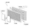
図1は、本実施形態に係る表示装置の概略構成を説明する分解斜視図である。本実施形態に係る表示装置1は、光変調部10、光源20、検出部30および制御部40を備えている。
<1. Schematic configuration of display device>
[Arrangement of components]
FIG. 1 is an exploded perspective view illustrating a schematic configuration of a display device according to the present embodiment. The
光変調部10は、映像信号により光を変調する。例えば、液晶パネルから成り、映像信号に応じて光源20の光を画素単位で変調し、映像表示を行う。
The
光源20は、光変調部に光を供給する。例えば、例えば冷陰極管(CCFL:Cold Cathode Fluorescent Lamp)が用いられる。本実施形態では、特に、輝度の変動によって色度が変化する光源20を用いる場合に有効である。
The
検出部30は、光源20から出射される光の量を検出する部分である。制御部40は、検出部30で検出した光量から輝度を求め、予め設定された色温度および輝度になるよう光変調部10へ供給する映像信号を補正する制御を行う。
The
表示装置1において、光変調器10は複数の画素がマトリクス状に配置されたパネル形状となっている。また、光源20も光変調器10の大きさに対応したパネル形状となっている。光源20としてCCFLを適用する場合、複数本のCCFLがパネル面に所定ピッチで配列され、光変調部10の全面について光を供給できるようになっている。光源20は、光変調部10の背面(映像表示面と反対側)に配置され、光変調部10の背面から光を供給する。
In the
検出部30は、光源20の背面(光変調部10が配置される面と反対側)に配置され、光源20の光量を検出する。また、光源20の背面には制御部40が設けられている。制御部40は各種回路を基板に備えた構成となっている。
The
これら光変調部10、光源20、検出部30および制御部40は、図示しない筐体内に組み込まれている。
The
[ブロック構成]
図2は、表示装置のブロック構成を説明する図である。先に説明した光変調部10と光源20とは重ね合わせて配置されることで表示ユニットを構成している。表示ユニットにおける光源20の背面側に検出部30が配置され、光源20の背面側に照射される光の量を検出する。光源20の背面側に照射される光は、光変調部10が配置される表面側に照射される光と同様な光であり、背面側の光量を検出することで光変調部10への光量を検出することと等しくなる。なお、光源20の背面側に反射膜が設けられている場合には、反射膜を透過した光を検出するか、検出器30の受光部分だけ反射膜に穴を開けておき、この穴を介して光源20から照射される光を検出することになる。
[Block configuration]
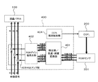
FIG. 2 is a diagram illustrating a block configuration of the display device. The
制御部40は、光源制御部41と映像制御部42とを備えている。検出部30で検出した信号は光源制御部41の演算部41aに送られ、色温度や輝度への変換、調整値等の算出など、各種の演算が行われる。光源制御部41は、光源20に対して制御信号を送り、光源20の発光量(輝度)を制御する。制御信号は、例えばPWM(Pulse Width Modulation)による信号である。
The
光源制御部40は、演算部41aで演算した調整値を映像制御部42へ送り、映像信号を補正する制御を行う。映像制御部42は、外部の映像入力端子(例えば、HDMI(High-Definition Multimedia Interface)、DVI(Digital Visual Interface)、拡張スロット)から入力される映像信号に基づき光変調器10の画素ごとの変調を制御する。
The light
光源制御部41および映像制御部42には電源制御部43から電源が供給される。電源制御部43から送られる電源電位は光源制御部41を介して光源10に与えられ、映像制御部42を介して光変調部10に与えられる。
Power is supplied from the
[表示動作(制御方法)]
図1、図2に示す表示装置1の表示動作を説明する。先ず、外部の映像入力端子(HDMI/DVI、拡張スロット等)から映像信号が入力されると、これを受けた映像制御部42はR(赤)、G(緑)、B(青)に対応した画素に対して駆動のための信号を与える。
[Display operation (control method)]
The display operation of the
一方、光源制御部41は、光源20に制御信号を与えて所定の輝度で光源20から光変調部10に光を供給する。光変調部10に供給された光は、映像信号に応じて駆動される画素ごと変調が行われ、RGBの各色に応じた強度となって出力される。これにより映像が表示されることになる。
On the other hand, the light
また、本実施形態の表示装置1では、光源20の光量を検出部30で検出し、光源制御部41の演算部41aで予め設定された色温度および輝度になるよう映像信号の調整値を算出している。この調整値は映像制御部42に送られ、映像制御部42から光変調部10に送られる映像信号に調整が加えられる。これにより、光源20の輝度が変更された場合でも、その輝度の変更によるRGBの色度のずれを調整し、予め定められた色温度および輝度に設定することが可能となる。
Further, in the
以下、本実施形態の表示装置1における具体的な実施形態を説明する。
Hereinafter, specific embodiments of the
<2.第1実施形態>
[ブロック構成]
図3は、第1実施形態に係る表示装置を説明するブロック図である。第1実施形態では、光変調部として液晶パネル100、光源としてCCFL200、検出部として光センサ300、制御部として制御ユニット400を用いている。
<2. First Embodiment>
[Block configuration]
FIG. 3 is a block diagram illustrating the display device according to the first embodiment. In the first embodiment, the
この表示装置では、CCFL200をバックライトとして液晶パネル100に光を供給する。液晶パネル100は制御ユニット400から送られる映像信号に基づく駆動信号によって画素毎の液晶が駆動される。これにより、CCFL200から供給された光を変調し、映像出力を行う。
In this display device, light is supplied to the
光センサ300は、CCFL200の光量を検出し、制御ユニット400に送る。制御ユニット400には、光源制御部41および映像制御部42(図2参照)が設けられている。これにより、光センサ300で検出した光量から色度情報および輝度情報を算出し、予め設定された色温度および輝度になるよう映像信号を補正する。また、この補正によってCCFL200の輝度が変化した分、CCFL200の輝度を補正する制御を行う。
The
[動作]
第1実施形態に係る表示装置は、次のような動作となる。先ず、制御ユニット400は、外部から映像信号が与えられると、この映像信号に基づき液晶パネル100の各画素を駆動する。これにより、液晶パネル100に映像を表示される。
[Operation]
The display device according to the first embodiment operates as follows. First, when a video signal is given from the outside, the
映像表示を行うにあたり、液晶パネル100のバックライトとして用いられるCCFL200は、制御ユニット400から送られる制御信号(例えば、PWMによる信号)によって光量が制御される。
In displaying video, the
CCFL200から液晶パネル100に光を供給する際、光センサ300でCCFL200の光量を検出する。光センサ300で検出した光量は、制御ユニット400に送られる。制御ユニット400は、光センサ300から送られた検出光量から色度情報および輝度情報を算出する。
When light is supplied from the
制御ユニット400は、予め設定された色温度(例えば、D65、D50といったホワイトバランス)および輝度と、検出光量から算出した色度情報および輝度情報とから調整値を算出する。また、制御ユニット400は、算出した調整値によって映像信号を補正し、液晶パネル100に与える。さらに、制御ユニット400は、調整値による映像信号の補正分で変化する輝度を補うため、CCFL200の輝度を補正する。
The
このCCFL200の補正後の輝度を光センサ300で検出し、制御ユニット400へ帰還する。このようなCCFL200の光量検出、色度調整、輝度補正を繰り返し実施することで、CCFL200を予め設定された色温度および輝度に合わせることができる。
The corrected brightness of the
<3.第2実施形態>
[ブロック構成]
図4は、第2実施形態に係る表示装置を説明するブロック図である。第2実施形態では、光変調部として液晶パネル100、光源としてCCFL200、検出部としてRGBセンサ301、制御部として制御ユニット400を用いている。
<3. Second Embodiment>
[Block configuration]
FIG. 4 is a block diagram illustrating a display device according to the second embodiment. In the second embodiment, the
この表示装置では、CCFL200をバックライトとして液晶パネル100に光を供給する。液晶パネル100は制御ユニット400から送られる映像信号に基づく駆動信号によって画素毎の液晶が駆動される。これにより、CCFL200から供給された光を変調し、映像出力を行う。
In this display device, light is supplied to the
RGBセンサ301は、CCFL200の光量をR(赤)、G(緑)、B(青)の各色ごとに検出し、制御ユニット400に送る。制御ユニット400には、検出値/色度・輝度変換部401と、RGBゲイン値算出部402と、RGBアンプ部403と、CCFL輝度制御部404とが設けられている。
The
これにより、CCFL輝度制御部404から送られる制御信号によってCCFL200の輝度が調整される。また、RGBセンサ301で検出したRGB各色の光量が、検出値/色度・輝度変換部401でRGB各色の色度情報および輝度情報に変換される。このRGB各色の色度情報および輝度情報が予め設定された色温度および輝度になるようRGB映像信号のゲイン値がRGBゲイン値算出部402で算出される。このゲイン値によりRGBアンプ部403でRGB映像信号が調整され、調整後の映像信号が液晶パネル100に送られる。
Thereby, the brightness of
[動作]
第2実施形態に係る表示装置は、次のような動作となる。先ず、制御ユニット400のRGBアンプ部403は、外部からRGB各色の映像信号が与えられると、このRGB映像信号に基づき液晶パネル100のRGBに対応した各画素を駆動する。これにより、液晶パネル100に映像を表示される。
[Operation]
The display device according to the second embodiment operates as follows. First, the
映像表示を行うにあたり、液晶パネル100のバックライトとして用いられるCCFL200は、制御ユニット400のCCFL輝度制御部404から送られる制御信号(例えば、PWMによる信号)によって光量が制御される。
When performing video display, the amount of light of
CCFL200から液晶パネル100に光を供給する際、RGBセンサ301でCCFL200の光量をRGB各色ごとに分けて検出する。RGBセンサ301で検出したRGB各色の光量は、制御ユニット400の検出値/色度・輝度変換部401に送られる。
When light is supplied from the
検出値/色度・輝度変換部401は、RGBセンサ301から送られたRGBの各検出光量からRGB各々についての色度情報(例えば、xy表色系における単色色度の座標(x,y))および輝度情報(例えば、単色輝度の値Y)を算出する。RGB各色ごとの色度情報および輝度情報はRGBゲイン値算出部402に送られる。
The detection value / chromaticity /
RGBゲイン値算出部402は、検出値/色度・輝度変換部401から送られてきたRGB各色の色度情報および輝度情報と、予め設定された色温度(例えば、D65、D50といったホワイトバランス)および輝度との相違からRGB各色の映像信号のレベルを補正するゲイン(調整値)を算出する。このゲインはRGBアンプ部403に送られる。
The RGB gain
RGBアンプ部403は、RGBゲイン値算出部402から送られたRGB各色のゲインを入力されるRGB各色の映像信号に各々与え、映像信号に補正を施す。補正後のRGB映像信号は液晶パネル100に送られ、これによって予め設定された色温度および輝度の映像表示が行われる。
The
<4.第3実施形態>
[ブロック構成]
図5は、第3実施形態に係る表示装置を説明するブロック図である。第3実施形態では、光変調部として液晶パネル100、光源としてCCFL200、検出部としてRGBセンサ301、制御部として制御ユニット400を用いている。
<4. Third Embodiment>
[Block configuration]
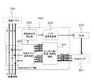
FIG. 5 is a block diagram illustrating a display device according to the third embodiment. In the third embodiment, the
この表示装置では、CCFL200をバックライトとして液晶パネル100に光を供給する。液晶パネル100は制御ユニット400から送られる映像信号に基づく駆動信号によって画素毎の液晶が駆動される。これにより、CCFL200から供給された光を変調し、映像出力を行う。
In this display device, light is supplied to the
RGBセンサ301は、CCFL200の光量をR(赤)、G(緑)、B(青)の各色ごとに検出し、制御ユニット400に送る。制御ユニット400には、検出値/色度・輝度変換部401と、RGBゲイン値算出部402と、RGBアンプ部403と、CCFL輝度制御部404と、輝度補正率算出部405とが設けられている。
The
これにより、CCFL輝度制御部404から送られる制御信号によってCCFL200の輝度が調整される。また、RGBセンサ301で検出したRGB各色の光量が、検出値/色度・輝度変換部401でRGB各色の色度情報および輝度情報に変換される。このRGB各色の色度情報および輝度情報が予め設定された色温度および輝度になるようRGB映像信号のゲイン値がRGBゲイン値算出部402で算出される。
Thereby, the brightness of
このゲイン値によりRGBアンプ部403でRGB映像信号が調整され、調整後の映像信号が液晶パネル100に送られる。さらに、映像信号の調整によって輝度が変動する分を補うよう輝度補正率算出部405が輝度の補正率を算出する。この補正率を用いてCCFL輝度制御部404がCCFL200の輝度を制御する。
The
[動作]
第3実施形態に係る表示装置は、次のような動作となる。先ず、制御ユニット400のRGBアンプ部403は、外部からRGB各色の映像信号が与えられると、このRGB映像信号に基づき液晶パネル100のRGBに対応した各画素を駆動する。これにより、液晶パネル100に映像を表示される。
[Operation]
The display device according to the third embodiment operates as follows. First, the
映像表示を行うにあたり、液晶パネル100のバックライトとして用いられるCCFL200は、制御ユニット400のCCFL輝度制御部404から送られる制御信号(例えば、PWMによる信号)によって光量が制御される。
When performing video display, the amount of light of
CCFL200から液晶パネル100に光を供給する際、RGBセンサ301でCCFL200の光量をRGB各色ごとに分けて検出する。RGBセンサ301で検出したRGB各色の光量は、制御ユニット400の検出値/色度・輝度変換部401に送られる。検出値/色度・輝度変換部401は、RGBセンサ301から送られたRGBの各検出光量からRGB各々についての色度情報(例えば、xy表色系における単色色度の座標(x,y))および輝度情報(例えば、単色輝度の値Y)を算出する。RGB各色ごとの色度情報および輝度情報はRGBゲイン値算出部402に送られる。
When light is supplied from the
RGBゲイン値算出部402は、検出値/色度・輝度変換部401から送られてきたRGB各色の色度情報および輝度情報と、予め設定された色温度(例えば、D65、D50といったホワイトバランス)および輝度との相違からRGB各色の映像信号のレベルを補正するゲイン(調整値)を算出する。このゲインはRGBアンプ部403に送られる。
The RGB gain
RGBアンプ部403は、RGBゲイン値算出部402から送られたRGB各色のゲインを入力されるRGB各色の映像信号に各々与え、映像信号に補正を施す。補正後のRGB映像信号は液晶パネル100に送る。
The
また、RGBゲイン値算出部402で算出したゲインは、輝度補正率算出部405にも送られる。輝度補正率算出部405は、RGBゲイン値算出部402から送られたRGB各色のゲインから調整後のRGB映像信号より輝度の変化分を求め、これを補うよう補正率を算出する。この補正率を用いて、CCFL輝度制御部404はCCFL200の輝度を制御する。
The gain calculated by the RGB gain
CCFL200の光量は、逐次RGBセンサ301によって検出される。したがって、CCFL輝度制御部404によるCCFL200の輝度の補正が行われた後も、補正後の光量をRGBセンサ301で検出する。この検出値は再度制御ユニット400に送られる。そして、検出値/色度・輝度変換部401による変換演算、RGBゲイン値算出部402によるゲイン値算出、RGBアンプ部403によるRGB映像信号の調整が繰り返し行われることになる。これによって予め設定された色温度および輝度の映像表示が行われる。
The light quantity of the
<5.具体例>
[ブロック構成]
図6は、本実施形態に係る表示装置の具体例を説明する機能ブロック図である。この図6では、主として図5に示す第3実施形態に係る表示装置の制御ユニット400内での各部の動作を機能ブロック(括弧内符号参照)として示したものである。
<5. Specific example>
[Block configuration]
FIG. 6 is a functional block diagram illustrating a specific example of the display device according to the present embodiment. In FIG. 6, the operation of each unit in the
[各部の機能の説明]
(1)…外部からの映像信号を赤色(R)映像信号、緑色(G)映像信号、青色(B)映像信号に変換する処理を行う。
(2)…デガンマにより、映像信号のγカーブをリニアな信号に変換する処理を行う。
(3)…RGB映像信号にゲインをかけて、RGB各色の信号レベルを補正する処理を行う。
(4)…液晶パネルのγカーブを加味して、リニアな映像信号をγカーブの信号に変換する処理を行う。
(5)…液晶パネルの表示におけるユニフォミティ(均一性)を補正する処理を行う。
(6)…設定色度輝度とRGBセンサからの色度輝度情報より、映像信号を補正するためのRGB各色のゲインを各々算出する処理を行う。
(7)…RGB各色のゲインにより変化する輝度量およびRGBセンサからの輝度情報により、輝度を補正するためのゲインを算出する処理を行う。
(8)…RGBセンサからの輝度情報を色度情報に変換する処理を行う。
(9)…(7)で算出されたゲインにより、目標輝度値を求める処理を行う。
(10)…(7)で算出されたゲインにより、目標PWM値を求める処理を行う。
(11)…目標輝度値とRGBセンサからの輝度値との比率より、フィードバック係数を算出する処理を行う。
(12)…発振防止のため、フィードバック係数のフィルタを施す。
(13)…目標PWM値にフィードバック係数を掛けて、CCFLへのPWM値を算出する処理を行う。
(14)…RGB各色の輝度を合成して白輝度を算出する処理を行う。
(15)…RGBセンサの出力値をRGB各色の輝度情報に変換する処理を行う。
[Description of functions of each part]
(1)... Processing for converting an external video signal into a red (R) video signal, a green (G) video signal, and a blue (B) video signal.
(2)... A process of converting the γ curve of the video signal into a linear signal by degamma.
(3)... A process of applying a gain to the RGB video signal to correct the signal level of each RGB color.
(4)... Processing for converting a linear video signal into a γ curve signal in consideration of the γ curve of the liquid crystal panel.
(5) A process for correcting uniformity (uniformity) in the display of the liquid crystal panel is performed.
(6)... Processing for calculating each RGB gain for correcting the video signal from the set chromaticity luminance and the chromaticity luminance information from the RGB sensor.
(7)... A process for calculating a gain for correcting the luminance is performed based on the luminance amount changing with the gain of each RGB color and the luminance information from the RGB sensor.
(8)... Processing for converting luminance information from the RGB sensor into chromaticity information.
(9)... Processing for obtaining the target luminance value is performed using the gain calculated in (7).
(10)... Processing for obtaining the target PWM value is performed using the gain calculated in (7).
(11)... Processing for calculating a feedback coefficient is performed based on the ratio between the target luminance value and the luminance value from the RGB sensor.
(12)... A feedback coefficient filter is applied to prevent oscillation.
(13)... Processing for calculating the PWM value to the CCFL by multiplying the target PWM value by the feedback coefficient.
(14)... Processing for calculating the white luminance by combining the luminances of the RGB colors.
(15)... Processing for converting the output value of the RGB sensor into luminance information of each color of RGB.
上記の機能のうち(8)、(14)、(15)は図5に示す検出値/色度・輝度変換部401で行われる。また、上記の機能うち(6)は図5に示すRGBゲイン値算出部402で行われる。また、上記の機能のうち(3)は図5に示すRGBアンプ部403で行われる。また、上記の機能のうち(9)、(10)は図5に示すCCFL輝度制御部404で行われる。また、上記の機能のうち(7)は図5に示す輝度補正率算出部405で行われる。
Of the above functions, (8), (14), and (15) are performed by the detection value / chromaticity /
[動作]
次に、図6に示す表示装置の具体例における動作を説明する。
[Operation]
Next, the operation of the specific example of the display device shown in FIG. 6 will be described.
(動作1)
RGBセンサで検出した値を(15)にて、RGB3原色の各色の輝度情報に変換する。変換は予め色毎に用意した定数aおよびbを使用し、以下の一次式より算出する。なお、ここで、赤色についての定数a、bをそれぞれar、br、緑色についての定数a、bをそれぞれag、bg、青色についての定数a、bをそれぞれab、bbとする。
(Operation 1)
The value detected by the RGB sensor is converted into luminance information of each of the three primary colors of RGB at (15). The conversion uses constants a and b prepared for each color in advance, and is calculated from the following linear expression. Here, constants a and b for red are a r and b r , constants a and b for green are a g and b g , and constants a and b for blue are a b and b b , respectively. To do.
赤色輝度情報=赤色輝度定数ar×赤色センサ値+赤色輝度定数br
緑色輝度情報=緑色輝度定数ag×緑色センサ値+緑色輝度定数bg
青色輝度情報=青色輝度定数ab×青色センサ値+青色輝度定数bb
Red luminance information = red luminance constant a r × red sensor value + red luminance constant b r
Green luminance information = green luminance constant a g × green sensor value + green luminance constant b g
Blue luminance information = blue luminance constant a b × blue sensor value + blue luminance constant b b
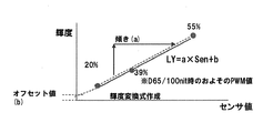
ここで、定数の求め方を図7を用いて説明する。図7は、横軸がRGBセンサの検出値(「RGBセンサ値」とも言う。)、縦軸が輝度を示している。先ず、表示装置の組立調整時にCCFLのPWM値を20%と39%、55%の3ポイントに設定し、各ポイントでのRGBセンサ値を求める。ここで、PWM39%は、白基準D65、光量100nitでのおおよそのPWM値である。
Here, how to obtain the constant will be described with reference to FIG. In FIG. 7, the horizontal axis indicates the detection value of the RGB sensor (also referred to as “RGB sensor value”), and the vertical axis indicates the luminance. First, at the time of assembly adjustment of the display device, the PWM value of CCFL is set to 3 points of 20%, 39% and 55%, and RGB sensor values at each point are obtained. Here,
そして、RGB各単色の映像信号を液晶パネルに入力した際の液晶パネルの映像表示面での輝度を測定する。図7には、3ポイントにおけるRGBセンサ値と液晶パネル表示面での輝度との関係がプロットされている。この3ポイントのプロットのうち、PWM値20%と55%との値を直線で結び、この直線から傾きを求めて定数aとする。また、この傾きでPWM39%の値を通過する直線の輝度軸上での切片をオフセット値の定数bとする。
Then, the luminance on the video display surface of the liquid crystal panel when the RGB single color video signals are input to the liquid crystal panel is measured. FIG. 7 plots the relationship between the RGB sensor values at three points and the luminance on the liquid crystal panel display surface. Among the three-point plots, the PWM values of 20% and 55% are connected by a straight line, and the slope is obtained from the straight line to obtain a constant a. Further, an intercept on the luminance axis of a straight line passing through a value of
このような定数aおよびbをRGB各色について求めておき、不揮発性メモリ等に記憶しておく。RGB各色についての定数a、bはCCFLと液晶パネルとの組み合わせ(図2に示す表示ユニット)ごとに求められるもので、求められたRGB各色の定数a、bは、例えば図2に示す構成における光源制御部41の演算部41a内に設けられる不揮発性メモリに記憶される。したがって、表示ユニットが交換された場合には、不揮発性メモリの内容を予め求めておいたその表示ユニットに対応した定数a、bに書き替えるようにする。なお、不揮発性メモリが表示ユニット内に設けられており、その表示ユニットに対応した定数a、bが記憶されている場合には、表示ユニットの交換のみでよい。
Such constants a and b are obtained for each color of RGB and stored in a nonvolatile memory or the like. Constants a and b for each of the RGB colors are obtained for each combination of the CCFL and the liquid crystal panel (display unit shown in FIG. 2). The obtained constants a and b for each of the RGB colors are, for example, in the configuration shown in FIG. It is stored in a nonvolatile memory provided in the
(動作2)
次に、動作1で算出したRGB各色の輝度を合成して白色の輝度を算出する。すなわち、算出した値は、RGBセンサによって検出した光量より得たCCFLの輝度情報となる。
(Operation 2)
Next, the luminance of each of the RGB colors calculated in
(動作3)
次に、動作2で求めた白色輝度から(8)によってRGB各色の色度座標(x、y)に変換する。変換は予め色毎に用意した定数AおよびBを使用し、以下の一次式より算出する。なお、ここで、赤色色度xについての定数A、BをそれぞれAxr、Bxr、赤色色度yについての定数A、BをそれぞれAyr、Byr、緑色色度xについての定数A、BをそれぞれAxg、Bxg、緑色色度yについての定数A、BをそれぞれAyg、Byg、青色色度xについての定数A、BをそれぞれAxb、Bxb、青色色度yについての定数A、BをそれぞれAyb、Bybとする。
(Operation 3)
Next, the white luminance obtained in the
赤色色度x=赤色色度x定数Axr×白色輝度値+赤色色度x定数Bxr
赤色色度y=赤色色度y定数Ayr×白色輝度値+赤色色度y定数Byr
緑色色度x=緑色色度x定数Axg×白色輝度値+緑色色度x定数Bxg
緑色色度y=緑色色度y定数Ayg×白色輝度値+緑色色度y定数Byg
青色色度x=青色色度x定数Axb×白色輝度値+青色色度x定数Bxb
青色色度y=青色色度y定数Ayb×白色輝度値+青色色度y定数Byb
Red chromaticity x = red chromaticity x constant A xr × white luminance value + red chromaticity x constant B xr
Red chromaticity y = red chromaticity y constant A yr × white luminance value + red chromaticity y constant B yr
Green chromaticity x = green chromaticity x constant A xg × white luminance value + green chromaticity x constant B xg
Green chromaticity y = green chromaticity y constant A yg × white luminance value + green chromaticity y constant B yg
Blue chromaticity x = blue chromaticity x constant A xb × white luminance value + blue chromaticity x constant B xb
Blue chromaticity y = blue chromaticity y constant A yb × white luminance value + blue chromaticity y constant B yb
ここで、定数の求め方を図8を用いて説明する。図8は、横軸が白色輝度、縦軸が色度を示している。先ず、表示装置の組立調整時にCCFLのPWM値を20%と39%、55%の3ポイントに設定し、各ポイントでのRGBセンサ値を求める。ここで、PWM39%は、白基準D65、光量100nitでのおおよそのPWM値である。
Here, how to obtain the constant will be described with reference to FIG. In FIG. 8, the horizontal axis represents white luminance, and the vertical axis represents chromaticity. First, at the time of assembly adjustment of the display device, the PWM value of CCFL is set to 3 points of 20%, 39% and 55%, and RGB sensor values at each point are obtained. Here,
そして、RGB各単色の映像信号を液晶パネルに入力した際の液晶パネルの映像表示面での色度を測定する。また、各ポイントで求めたRGBセンサ値から上記動作1〜2の処理によって、各ポイントでの白色輝度を算出する。図8には、3ポイントにおける白色輝度と液晶パネル表示面での色度との関係がプロットされている。この3ポイントのプロットのうち、PWM値20%と55%との値を直線で結び、この直線から傾きを求めて定数Aとする。また、この傾きでPWM39%の値を通過する直線の色度軸上での切片をオフセット値の定数Bとする。
Then, the chromaticity on the video display surface of the liquid crystal panel when the RGB single color video signals are input to the liquid crystal panel is measured. Further, the white luminance at each point is calculated from the RGB sensor values obtained at each point by the processes of the
このような定数AおよびBをRGB各色のx、y各色度について求めておき、不揮発性メモリ等に記憶しておく。定数A、Bは、定数a、bと同様、CCFLと液晶パネルとの組み合わせ(図2に示す表示ユニット)ごとに求められるもので、例えば図2に示す演算部41a内や表示ユニット内に設けられる不揮発性メモリに記憶される。
Such constants A and B are obtained for the x and y chromaticities of the RGB colors and stored in a nonvolatile memory or the like. The constants A and B are obtained for each combination of the CCFL and the liquid crystal panel (display unit shown in FIG. 2) like the constants a and b. For example, the constants A and B are provided in the
(動作4)
次に、算出したRGB各色の色度情報および輝度情報より、(6)にてCCFLが変動したことによる色度・輝度を補正するため、映像信号へ掛けるゲインを算出する。このゲインはRGBの各映像信号にそれぞれに掛けるため、Rゲイン、Gゲイン、Bゲインとして3種類を求める。RGBの各ゲインは次のような手順で求める。
(Operation 4)
Next, in order to correct the chromaticity / brightness due to the change of the CCFL in (6) from the calculated chromaticity information and luminance information of each RGB color, a gain to be applied to the video signal is calculated. Since this gain is applied to each of the RGB video signals, three types of R gain, G gain, and B gain are obtained. Each gain of RGB is obtained by the following procedure.
図9は、RGBの各ゲインの算出を説明する図で、xy色空間上での設定色度とRGBセンサの検出値による各色の色度との関係を示している。
「1」…目標とする色度xと赤色色度xとの距離Aを算出する。
距離A=設定色度x−RGBセンサからの赤色色度x
「2」…目標とする色度xと緑色色度xとの距離Bを算出する。
距離B=設定色度x−RGBセンサからの緑色色度x
「3」…目標とする色度xと青色色度xとの距離Cを算出する。
距離C=設定色度x−RGBセンサからの青色色度x
FIG. 9 is a diagram for explaining the calculation of each gain of RGB, and shows the relationship between the set chromaticity in the xy color space and the chromaticity of each color based on the detection value of the RGB sensor.
“1”: A distance A between the target chromaticity x and the red chromaticity x is calculated.
Distance A = set chromaticity x-red chromaticity x from RGB sensor
“2”: A distance B between the target chromaticity x and the green chromaticity x is calculated.
Distance B = set chromaticity x-green chromaticity x from RGB sensor
“3”: The distance C between the target chromaticity x and the blue chromaticity x is calculated.
Distance C = set chromaticity x-blue chromaticity x from RGB sensor
「4」…目標とする色度yと赤色色度yとの距離Dを算出する。
距離D=RGBセンサからの赤色色度y−設定色度y
「5」…目標とする色度yと緑色色度yとの距離Eを算出する。
距離E=RGBセンサからの緑色色度y−設定色度y
「6」…目標とする色度yと青色色度yとの距離Fを算出する。
距離F=RGBセンサからの青色色度y−設定色度y
“4”... Distance D between target chromaticity y and red chromaticity y is calculated.
Distance D = Red chromaticity y from RGB sensor−set chromaticity y
“5”... Distance E between target chromaticity y and green chromaticity y is calculated.
Distance E = green chromaticity y from RGB sensor−set chromaticity y
“6”: The distance F between the target chromaticity y and the blue chromaticity y is calculated.
Distance F = Blue chromaticity y from RGB sensor−set chromaticity y
「7」…赤と青との色度yの差Gを算出する。
差G=RGBセンサからの青色色度y−RGBセンサからの赤色色度y
「8」…赤と緑との色度yの差Hを算出する。
差H=RGBセンサからの緑色色度y−RGBセンサからの赤色色度y
「9」…青と緑との色度yの差Iを算出する。
差I=RGBセンサからの青色色度y−RGBセンサからの緑色色度y
“7”... The difference G of chromaticity y between red and blue is calculated.
Difference G = Blue chromaticity y from RGB sensor-Red chromaticity y from RGB sensor
“8”: The difference H in chromaticity y between red and green is calculated.
Difference H = Green chromaticity y from RGB sensor-Red chromaticity y from RGB sensor
“9”: The difference I in chromaticity y between blue and green is calculated.
Difference I = Blue chromaticity y from RGB sensor−Green chromaticity y from RGB sensor
「10」…RGB3原色を合成した際に設定色度になるような赤の輝度Yrを算出する。
輝度Yr=−1×RGBセンサからの赤色色度y×(C×E−B×F)÷(設定色度y×(B×G−C×H−A×I))
「11」…RGB3原色を合成した際に設定色度になるような緑の輝度Ygを算出する。
輝度Yg=1×RGBセンサからの緑色色度y×(C×D−A×F)÷(設定色度y×(B×G−C×H−A×I))
「12」…RGB3原色を合成した際に設定色度になるような青の輝度Ybを算出する。
輝度Yb=1−Yr−Yg
“10”... Red luminance Yr is calculated so that the set chromaticity is reached when the three primary colors RGB are synthesized.
Luminance Yr = −1 × Red chromaticity y × (C × EB × F) ÷ (set chromaticity y × (B × GC−HA × I)) from RGB sensor
“11”... Green luminance Yg is calculated such that the set chromaticity is obtained when the RGB three primary colors are combined.
Luminance Yg = 1 × green chromaticity y × (C × D−A × F) ÷ (set chromaticity y × (B × GC × H−A × I)) from RGB sensor
“12”... Blue luminance Yb is calculated so that the set chromaticity is obtained when the three primary colors RGB are synthesized.
Luminance Yb = 1−Yr−Yg
「13」…RGBセンサから取得した現在のRGB各色の輝度と、「10」〜「12」で計算より求めた輝度と比率から、R、G、Bの各ゲインを求める。
Rゲイン=Yr×RGBセンサ値から求めた白色輝度÷RGBセンサ値から求めた赤色輝度
Gゲイン=Yg×RGBセンサ値から求めた白色輝度÷RGBセンサ値から求めた緑色輝度
Bゲイン=Yb×RGBセンサ値から求めた白色輝度÷RGBセンサ値から求めた青色輝度
“13”: R, G, and B gains are obtained from the brightness of each current RGB color acquired from the RGB sensor and the brightness and ratio obtained by calculation from “10” to “12”.
R gain = Yr × white luminance obtained from RGB sensor value ÷ red luminance obtained from RGB sensor value G gain = white luminance obtained from Yg × RGB sensor value ÷ green luminance obtained from RGB sensor value B gain = Yb × RGB White luminance obtained from sensor value ÷ Blue luminance obtained from RGB sensor value
その後、算出されたRGB各色のゲインが上限で1倍となるようにRGB3つのゲイン値を同じ比率で調整する。図10はRGBゲインの比率調整を説明する図である。この図では、算出されたRGB3つのゲインのうち、最も大きいRのゲインに合わせている例を示している。すなわち、Rのゲインを1倍にする際の比率をGおよびBのゲインにも掛けて、最大のゲインが1倍となるよう調整する。 Thereafter, the three RGB gain values are adjusted at the same ratio so that the calculated gains of the respective RGB colors become 1 times at the upper limit. FIG. 10 is a diagram for explaining the RGB gain ratio adjustment. This figure shows an example in which the calculated gain is set to the largest R gain among the three gains of RGB. In other words, the ratio for multiplying the gain of R by 1 is also multiplied by the gains of G and B, and the maximum gain is adjusted to be 1.
(動作5)
次に、外部から入力された映像信号は(1)にてRGBに変換され、(2)にてデガンマされる。そのRGBの各映像信号に対して、先に算出したRGBゲインをRGBそれぞれの映像信号に対して(3)にて掛け合わせる。その後、(4)のガンマ補正、(5)のユニフォーミティ補正を行い液晶パネルに出力する。
(Operation 5)
Next, the video signal input from the outside is converted into RGB in (1) and de-gammad in (2). For each of the RGB video signals, the previously calculated RGB gain is multiplied by each of the RGB video signals in (3). Thereafter, (4) gamma correction and (5) uniformity correction are performed and output to the liquid crystal panel.
(動作6)
この時、RGBゲインにより表示パネルの映像表示面での輝度が変化することになる。そこで、(7)にてその輝度の変化率を求め、輝度の補正量(輝度補正ゲイン)を求める。実際には、映像信号に最大で1倍のゲインを掛けているので、輝度は下がる方向に働く。低下した輝度および輝度補正ゲインは次の式によって計算する。
(Operation 6)
At this time, the luminance on the video display surface of the display panel changes due to the RGB gain. Therefore, the luminance change rate is obtained in (7), and the luminance correction amount (luminance correction gain) is obtained. Actually, since the video signal is multiplied by a gain of 1 times at the maximum, the luminance works in a decreasing direction. The reduced brightness and brightness correction gain are calculated by the following formula.
低下した赤色輝度=RGBセンサでの検出値に基づく赤色輝度×Rゲイン
低下した緑色輝度=RGBセンサでの検出値に基づく緑色輝度×Gゲイン
低下した青色輝度=RGBセンサでの検出値に基づく青色輝度×Bゲイン
低下した白色輝度=低下した赤色輝度+低下した緑色輝度+低下した青色輝度
輝度補正ゲイン=輝度補正ゲイン×設定輝度÷低下した白色輝度
(但し、輝度補正ゲインの初期値は1とする)
Reduced red luminance = red luminance based on detection value at RGB sensor × R gain Reduced green luminance = green luminance × G gain based on detection value at RGB sensor Reduced blue luminance = blue based on detection value at RGB sensor Brightness x B gain Reduced white brightness = Reduced red brightness + Decreased green brightness + Reduced blue brightness Brightness correction gain = Brightness correction gain x Set brightness ÷ Decreased white brightness (However, the initial value of the brightness correction gain is 1. To do)
(動作7)
次に、輝度補正ゲインを(9)にて基準輝度値と掛け合わせ、目標輝度値を算出する。また、これと同時に(10)にて基準PWM値と掛け合わせ、目標PWM値を算出する。
(Operation 7)
Next, the luminance correction gain is multiplied by the reference luminance value in (9) to calculate a target luminance value. At the same time, the target PWM value is calculated by multiplying the reference PWM value in (10).
(動作8)
次に、目標輝度値と(14)からの白色輝度値の比率を(11)で求め、その値を輝度フィードバック係数とする。
(Operation 8)
Next, the ratio of the target luminance value and the white luminance value from (14) is obtained in (11), and that value is used as the luminance feedback coefficient.
(動作9)
次に、(13)にて目標PWM値に輝度フィードバック係数を掛けて、CCFLへ与えるPWM値を算出する。ここで、CCFLの輝度が上がり、それによりCCFLの色度も変わるが、その情報は白色輝度として反映され、それによりRGB各色の色度情報が変わることで自動的に補正されることになる。
(Operation 9)
Next, in (13), the target PWM value is multiplied by the luminance feedback coefficient to calculate the PWM value to be given to the CCFL. Here, the luminance of the CCFL increases, and the chromaticity of the CCFL also changes. However, the information is reflected as white luminance, and is automatically corrected by changing the chromaticity information of each color of RGB.
(動作10)
以上の動作をリアルタイムに繰り返し行うことにより、CCFLの色度や輝度が変動しても液晶パネルから出力される映像には影響を与えず、安定した色温度および輝度を実現することが可能となる。
(Operation 10)
By repeating the above operation in real time, even if the chromaticity and brightness of the CCFL fluctuate, it is possible to realize a stable color temperature and brightness without affecting the video output from the liquid crystal panel. .
<他の適用例>
上記説明した実施形態では、いずれの表示装置の例を示したが、図1および図2に示す光変調部10、光源20、検出器30および制御部40が全て表示ユニット内に組み込まれた構成であっても適用可能である。また、光源20のパネル内に検出器30および制御部40が組み込まれた表示装置用光源を構成してもよい。
<Other application examples>
In the above-described embodiment, an example of any display device is shown, but the configuration in which the
また、上記説明した各種計算式では色空間としてxy色空間による座標値を用いているが、他の色空間の座標値(例えば、La*b*におけるa*b*座標)を用いるようにしてもよい。 In the above-described various calculation formulas, coordinate values in the xy color space are used as the color space, but coordinate values in other color spaces (for example, a * b * coordinates in La * b * ) are used. Also good.
1…表示装置、10…光変調器、20…光源、30…検出部、40…制御部、41…光源制御部、41a…演算部、42…映像制御部、43…電源制御部、100…液晶パネル、200…CCFL、300…光センサ、301…RGBセンサ、400…制御ユニット
DESCRIPTION OF
Claims (9)
前記光変調部に光を供給する光源と、
前記光源の光量を検出する検出部と、
前記検出部で検出した光量から予め設定された色温度および輝度になるよう前記映像信号を補正する制御を行う制御部と
を有する表示装置。 An optical modulation unit that modulates light by a video signal;
A light source for supplying light to the light modulator;
A detection unit for detecting the light quantity of the light source;
A control unit that performs control to correct the video signal so that a color temperature and luminance set in advance from a light amount detected by the detection unit.
前記制御部は、前記検出部で検出したRGBの各々の光量から前記予め設定された色温度および輝度になるよう前記映像信号のRGBの調整値を算出し、当該調整値によって前記映像信号を補正する制御を行う
請求項1記載の表示装置。 The detection unit detects the light amount of the light source for each of R (red), G (green), and B (blue),
The control unit calculates an RGB adjustment value of the video signal from the RGB light amounts detected by the detection unit so as to be the preset color temperature and luminance, and corrects the video signal by the adjustment value. The display device according to claim 1, wherein control is performed.
前記検出部で検出したRGBの各々の光量を色度情報および輝度情報に変換する変換部と、
前記変換部で変換されたRGBの各々の色度情報および輝度情報から前記予め設定された色温度および輝度となるようRGB各々の前記調整値を算出する算出部とを有する
請求項2記載の表示装置。 The controller is
A conversion unit that converts each light quantity of RGB detected by the detection unit into chromaticity information and luminance information;
The display unit according to claim 2, further comprising: a calculation unit that calculates the adjustment values for each of RGB so as to obtain the preset color temperature and luminance from the chromaticity information and luminance information of each of RGB converted by the conversion unit. apparatus.
前記映像信号を補正した後の映像信号による映像出力についての輝度の変動分と前記予め設定された輝度との差から輝度の補正値を算出する輝度補正値算出部と、
前記輝度補正値算出部で算出した前記輝度の補正値により前記光源の輝度を制御する光源輝度制御部と
を有する請求項1から3のうちいずれか1項に記載の表示装置。 The controller is
A luminance correction value calculation unit that calculates a luminance correction value from a difference between a luminance variation of the video output by the video signal after correcting the video signal and the preset luminance;
The display device according to claim 1, further comprising: a light source luminance control unit that controls luminance of the light source based on the luminance correction value calculated by the luminance correction value calculation unit.
請求項4記載の表示装置。 The display device according to claim 4, further comprising: a configuration in which the light amount of the light source controlled by the light source luminance control unit is detected by the detection unit and returned to the control unit.
請求項1から5のうちいずれか1項に記載の表示装置。 The display device according to claim 1, wherein the light source has a chromaticity that changes due to a change in luminance.
請求項6記載の表示装置。 The display device according to claim 6, wherein the light source is a cold cathode tube.
請求項1から7のうちいずれか1項に記載の表示装置。 The display device according to claim 1, wherein the light modulation unit modulates light with liquid crystal.
検出した前記光量から予め設定された色温度および輝度になるよう前記映像信号を補正する制御を行う工程と
を有する表示装置の制御方法。 A step of detecting the amount of light from the light source when displaying the light supplied from the light source by modulating the video signal;
And a step of performing control to correct the video signal so that the detected light amount has a preset color temperature and luminance.
Priority Applications (3)
| Application Number | Priority Date | Filing Date | Title |
|---|---|---|---|
| JP2008323366A JP2010145773A (en) | 2008-12-19 | 2008-12-19 | Display device and method of controlling display device |
| US12/639,499 US8421813B2 (en) | 2008-12-19 | 2009-12-16 | Display device and method of controlling display device |
| CN200910261917.6A CN101751868B (en) | 2008-12-19 | 2009-12-21 | Display device and method of controlling display device |
Applications Claiming Priority (1)
| Application Number | Priority Date | Filing Date | Title |
|---|---|---|---|
| JP2008323366A JP2010145773A (en) | 2008-12-19 | 2008-12-19 | Display device and method of controlling display device |
Publications (2)
| Publication Number | Publication Date |
|---|---|
| JP2010145773A true JP2010145773A (en) | 2010-07-01 |
| JP2010145773A5 JP2010145773A5 (en) | 2011-12-08 |
Family
ID=42265370
Family Applications (1)
| Application Number | Title | Priority Date | Filing Date |
|---|---|---|---|
| JP2008323366A Pending JP2010145773A (en) | 2008-12-19 | 2008-12-19 | Display device and method of controlling display device |
Country Status (3)
| Country | Link |
|---|---|
| US (1) | US8421813B2 (en) |
| JP (1) | JP2010145773A (en) |
| CN (1) | CN101751868B (en) |
Cited By (5)
| Publication number | Priority date | Publication date | Assignee | Title |
|---|---|---|---|---|
| WO2012011169A1 (en) * | 2010-07-21 | 2012-01-26 | Necディスプレイソリューションズ株式会社 | Chromaticity correcting circuit, display device, and chromaticity correcting method |
| WO2013038560A1 (en) * | 2011-09-16 | 2013-03-21 | Necディスプレイソリューションズ株式会社 | Display device and method for correcting variations in display device |
| WO2014188533A1 (en) * | 2013-05-22 | 2014-11-27 | Necディスプレイソリューションズ株式会社 | Display device, display system, image output device, and method for controlling display device |
| JP2015114547A (en) * | 2013-12-12 | 2015-06-22 | 株式会社デンソー | Chromaticity correction device |
| WO2021033581A1 (en) * | 2019-08-21 | 2021-02-25 | 株式会社Jvcケンウッド | Light quantity control device, projection device, and light quantity control method |
Families Citing this family (10)
| Publication number | Priority date | Publication date | Assignee | Title |
|---|---|---|---|---|
| KR101861795B1 (en) * | 2011-03-24 | 2018-05-29 | 삼성디스플레이 주식회사 | Luminance Correction System for Organic Light Emitting Display Device |
| US20170295369A1 (en) * | 2014-10-06 | 2017-10-12 | Sony Corporation | Image processing device and method |
| CN104601971B (en) * | 2014-12-31 | 2019-06-14 | 小米科技有限责任公司 | Color adjustment method and device |
| CN105957471A (en) * | 2016-07-14 | 2016-09-21 | 武汉华星光电技术有限公司 | Color temperature adjustable display system and color temperature adjusting method |
| CN107154247A (en) * | 2017-06-19 | 2017-09-12 | 广东欧珀移动通信有限公司 | Color temperature adjusting method, device and its equipment reconstructed based on rgb light spectrum energy |
| CN107065274B (en) * | 2017-06-19 | 2020-03-10 | 上海天马微电子有限公司 | Array substrate, display panel and display device |
| TWI701950B (en) * | 2019-05-16 | 2020-08-11 | 鈺緯科技開發股份有限公司 | A display auto calibration device and the calibration method thereof |
| CN111951745A (en) * | 2019-05-16 | 2020-11-17 | 钰纬科技开发股份有限公司 | Image adjusting device of display and adjusting method thereof |
| CN110827769B (en) * | 2019-11-12 | 2021-09-21 | 昆山龙腾光电股份有限公司 | Adaptation device and display device |
| KR20210061038A (en) * | 2019-11-19 | 2021-05-27 | 삼성전자주식회사 | Display apparatus and control method thereof |
Citations (1)
| Publication number | Priority date | Publication date | Assignee | Title |
|---|---|---|---|---|
| JP2008116850A (en) * | 2006-11-07 | 2008-05-22 | Necディスプレイソリューションズ株式会社 | Liquid crystal display device and method for controlling liquid crystal display device |
Family Cites Families (9)
| Publication number | Priority date | Publication date | Assignee | Title |
|---|---|---|---|---|
| JPH07294889A (en) | 1994-04-27 | 1995-11-10 | Kansei Corp | Color liquid crystal display device |
| JP4050802B2 (en) | 1996-08-02 | 2008-02-20 | シチズン電子株式会社 | Color display device |
| JP2001265296A (en) | 2000-01-14 | 2001-09-28 | Sharp Corp | Transmission type liquid crystal display device and picture processing method |
| JP2002149135A (en) | 2000-11-13 | 2002-05-24 | Advanced Display Inc | Transmission type image display device, and device and method for adjustment |
| US7595811B2 (en) * | 2001-07-26 | 2009-09-29 | Seiko Epson Corporation | Environment-complaint image display system, projector, and program |
| US7893903B2 (en) * | 2004-06-21 | 2011-02-22 | Hitachi Displays, Ltd. | Liquid crystal display apparatus capable of maintaining high color purity |
| JP4182930B2 (en) | 2004-07-12 | 2008-11-19 | ソニー株式会社 | Display device and backlight device |
| JP4757577B2 (en) * | 2005-09-14 | 2011-08-24 | 日本電気株式会社 | Light source device, display device, terminal device, light source unit, and driving method of light source device |
| JP2008158454A (en) | 2006-12-26 | 2008-07-10 | Sony Corp | Liquid crystal display device |
-
2008
- 2008-12-19 JP JP2008323366A patent/JP2010145773A/en active Pending
-
2009
- 2009-12-16 US US12/639,499 patent/US8421813B2/en not_active Expired - Fee Related
- 2009-12-21 CN CN200910261917.6A patent/CN101751868B/en not_active Expired - Fee Related
Patent Citations (1)
| Publication number | Priority date | Publication date | Assignee | Title |
|---|---|---|---|---|
| JP2008116850A (en) * | 2006-11-07 | 2008-05-22 | Necディスプレイソリューションズ株式会社 | Liquid crystal display device and method for controlling liquid crystal display device |
Cited By (9)
| Publication number | Priority date | Publication date | Assignee | Title |
|---|---|---|---|---|
| WO2012011169A1 (en) * | 2010-07-21 | 2012-01-26 | Necディスプレイソリューションズ株式会社 | Chromaticity correcting circuit, display device, and chromaticity correcting method |
| JP5665147B2 (en) * | 2010-07-21 | 2015-02-04 | Necディスプレイソリューションズ株式会社 | Chromaticity correction circuit, display device, and chromaticity correction method |
| WO2013038560A1 (en) * | 2011-09-16 | 2013-03-21 | Necディスプレイソリューションズ株式会社 | Display device and method for correcting variations in display device |
| WO2014188533A1 (en) * | 2013-05-22 | 2014-11-27 | Necディスプレイソリューションズ株式会社 | Display device, display system, image output device, and method for controlling display device |
| US9812071B2 (en) | 2013-05-22 | 2017-11-07 | Nec Display Solutions, Ltd. | Display device, display system, video output device, and control method of display device |
| JP2015114547A (en) * | 2013-12-12 | 2015-06-22 | 株式会社デンソー | Chromaticity correction device |
| WO2021033581A1 (en) * | 2019-08-21 | 2021-02-25 | 株式会社Jvcケンウッド | Light quantity control device, projection device, and light quantity control method |
| JP2021032970A (en) * | 2019-08-21 | 2021-03-01 | 株式会社Jvcケンウッド | Amount-of-light adjustment device, projection device, and amount-of-light adjustment method |
| JP7284915B2 (en) | 2019-08-21 | 2023-06-01 | 株式会社Jvcケンウッド | Light quantity adjustment device, projection device, and light quantity adjustment method |
Also Published As
| Publication number | Publication date |
|---|---|
| CN101751868B (en) | 2014-05-07 |
| CN101751868A (en) | 2010-06-23 |
| US20100156927A1 (en) | 2010-06-24 |
| US8421813B2 (en) | 2013-04-16 |
Similar Documents
| Publication | Publication Date | Title |
|---|---|---|
| JP2010145773A (en) | Display device and method of controlling display device | |
| JP4539492B2 (en) | Backlight device, backlight driving method, and liquid crystal display device | |
| EP1650736A1 (en) | Backlight modulation for display | |
| WO2011043290A1 (en) | Liquid crystal display device | |
| WO2010146735A1 (en) | Display device and display control method | |
| JP5615226B2 (en) | LIGHT CONTROL DEVICE, ITS CONTROL METHOD, AND DISPLAY DEVICE | |
| JP4882657B2 (en) | Backlight control device, backlight control method, and liquid crystal display device | |
| US20090115720A1 (en) | Liquid crystal display, liquid crystal display module, and method of driving liquid crystal display | |
| JP2008304907A (en) | Liquid crystal display, and image display method used therefor | |
| JP2008203859A (en) | Image display device | |
| JP2005128254A (en) | Display characteristic calibration method, display characteristic calibration system, and computer program | |
| JP2010262288A (en) | Method for driving light source module | |
| KR101441383B1 (en) | Liquid crystal display device and method for driving the same | |
| KR101073006B1 (en) | Display device and method for controling brightness of images in display device | |
| US9779648B2 (en) | Display device for correcting white balance based on degradation and chromaticity control method thereof | |
| US7948499B2 (en) | Color control algorithm for use in display systems | |
| JP2008262032A (en) | Liquid crystal display device | |
| JP2019113653A (en) | Liquid crystal display device | |
| JP2008102490A (en) | Liquid crystal display device and liquid crystal television | |
| JP2006030416A (en) | Device and method for image display | |
| JP2006243576A (en) | Liquid crystal display device | |
| JP5076787B2 (en) | Image display device and image display method | |
| WO2014188531A1 (en) | Backlight device, display device, method for controlling backlight | |
| JP2014197038A (en) | Image display device and image display method | |
| JP2010117578A (en) | Display device, liquid crystal display device, and display method |
Legal Events
| Date | Code | Title | Description |
|---|---|---|---|
| A521 | Request for written amendment filed |
Free format text: JAPANESE INTERMEDIATE CODE: A523 Effective date: 20111026 |
|
| A621 | Written request for application examination |
Free format text: JAPANESE INTERMEDIATE CODE: A621 Effective date: 20111026 |
|
| A977 | Report on retrieval |
Free format text: JAPANESE INTERMEDIATE CODE: A971007 Effective date: 20120907 |
|
| A131 | Notification of reasons for refusal |
Free format text: JAPANESE INTERMEDIATE CODE: A131 Effective date: 20130312 |
|
| A521 | Request for written amendment filed |
Free format text: JAPANESE INTERMEDIATE CODE: A523 Effective date: 20130513 |
|
| A02 | Decision of refusal |
Free format text: JAPANESE INTERMEDIATE CODE: A02 Effective date: 20130604 |
|
| A521 | Request for written amendment filed |
Free format text: JAPANESE INTERMEDIATE CODE: A523 Effective date: 20130904 |
|
| A911 | Transfer to examiner for re-examination before appeal (zenchi) |
Free format text: JAPANESE INTERMEDIATE CODE: A911 Effective date: 20130911 |