JP2012154702A - Density measuring device - Google Patents
Density measuring device Download PDFInfo
- Publication number
- JP2012154702A JP2012154702A JP2011012440A JP2011012440A JP2012154702A JP 2012154702 A JP2012154702 A JP 2012154702A JP 2011012440 A JP2011012440 A JP 2011012440A JP 2011012440 A JP2011012440 A JP 2011012440A JP 2012154702 A JP2012154702 A JP 2012154702A
- Authority
- JP
- Japan
- Prior art keywords
- float
- elastic member
- floats
- density
- stem
- Prior art date
- Legal status (The legal status is an assumption and is not a legal conclusion. Google has not performed a legal analysis and makes no representation as to the accuracy of the status listed.)
- Granted
Links
Images


Abstract
Description
本発明は、給油設備の燃料貯蔵容器の燃料等の密度を検出することができる液面測定装置に付属する密度測定機能、特にフロートと弾性部材の構造に関する。 The present invention relates to a density measuring function attached to a liquid level measuring device capable of detecting the density of fuel or the like in a fuel storage container of a fueling facility, and more particularly to the structure of a float and an elastic member.
給油設備の燃料貯蔵容器の燃料の密度を検出する装置は、例えば特許文献1に見られるように駆動体と、この駆動体に係止し、自身の弾性変位が駆動体の駆動力を示す尺度であるバネと、例えば特許文献2に示されたようなバネの弾性変位を取得するための磁歪位置計測システムとより構成されている。
An apparatus for detecting the density of fuel in a fuel storage container of a fueling facility is, for example, as shown in
しかしながら、密度測定のためだけにマグネットを有するストッパを余分に必要とするため構造が複雑になるという問題がある。
このような問題を解消するため、出願人は特願2010−136930に示したような容器の底部に存在する水の深さに対応して移動する水フロートを磁歪線に摺動自在に配設し、一端に設けられた発信用スイッチにより前記磁歪線の他端に向けて電気信号を発信し、水フロートに設けられたマグネットとの磁気的に相互作用により生じる信号の到達時間を計測する磁歪式液面計測装置において、液の密度に対応して浮沈し、かつ磁歪線と磁気的に相互作用する密度フロートを水フロートの上部に弾性部材により連結して配置した密度測定装置を提案した。
However, there is a problem that the structure becomes complicated because an extra stopper having a magnet is required only for density measurement.
In order to solve such a problem, the applicant arranges a water float that moves in accordance with the depth of water present at the bottom of the container as shown in Japanese Patent Application No. 2010-136930 in a slidable manner on the magnetostrictive wire. The magnetostriction transmits an electrical signal to the other end of the magnetostrictive wire by a transmission switch provided at one end, and measures the arrival time of the signal generated by magnetic interaction with the magnet provided in the water float. In the liquid level measuring apparatus, a density measuring apparatus was proposed in which a density float that floats and sinks in accordance with the density of the liquid and that interacts magnetically with the magnetostrictive line is connected to the upper part of the water float by an elastic member.
これによれば既存の磁歪線式液面計の構造を利用して簡単な構造の密度度測定機能を有する液面計測装置を提供できるものの、フロートと弾性部材との結合構造が明確に規定されていないため、タンクへの注油に伴う激しい液面の変化や、液面計測装置の運搬時に構成部品に過剰な力が作用してフロート間に配置された弾性部材に塑性変形を生じさせるという不都合が見られた。 According to this, a liquid level measuring device having a simple density measurement function can be provided by using the structure of an existing magnetostrictive liquid level gauge, but the coupling structure between the float and the elastic member is clearly defined. Inconveniences such as drastic changes in the liquid level due to oiling to the tank and excessive deformation of the component parts during transportation of the liquid level measuring device, causing plastic deformation of the elastic members arranged between the floats. It was observed.
また、複数のフロートが弾性部材を介して同一軸上に上下関係となるように配置されているため、フロート間にオフセットが生じ、フロート間の最小距離に限界があり、計測可能な最小値に限界があった。 In addition, since multiple floats are arranged on the same axis in a vertical relationship via elastic members, there is an offset between floats, there is a limit on the minimum distance between floats, and the minimum measurable value. There was a limit.
本発明はこのような問題に鑑みてなされたものであってその目的とするところは、フロートと弾性部材との接触構造を改良して弾性部材の変形を防止することである。
また本発明の他の目的は、計測可能な最小値を可及的に最小化することである。
The present invention has been made in view of such problems, and an object of the present invention is to improve the contact structure between the float and the elastic member to prevent deformation of the elastic member.
Another object of the present invention is to minimize the minimum value that can be measured.
このような課題を解決するために請求項1の発明は、ステムに案内されて燃料油の密度に対応して浮沈する第一のフロートと、前記ステムに案内されて水の液位に対応して移動する第二のフロートと、第一と第二のフロートの間に位置し、前記第一のフロートの位置に対応して伸縮する弾性部材と、前記弾性部材の伸縮を検出する手段とを備え、前記第一と第二のフロートとのそれぞれの相対向する端部に、前記弾性部材の最大収縮時の全長程度の収容部材が設けられている。
In order to solve such a problem, the invention of
請求項2の発明は、前記収容部材の一方がフロートの本体に収まるように形成されている。 The invention according to claim 2 is formed so that one of the housing members is accommodated in the main body of the float.
請求項1の発明によれば収容部材により弾性部材が保護される。
According to the invention of
請求項2の発明によれば、請求項1の発明の効果に加えて第一と第二のフロートとの最小距離を、一方の収容部材の長さだけ短くできる。
According to the invention of claim 2, in addition to the effect of the invention of
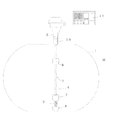
図1は本発明の一実施例を示すものであって、地下タンク1には地上に設けられたピットとの間にライザパイプ3が接続されていて、本発明が特徴とする液面検出装置4がタンク1に設置されている。
FIG. 1 shows an embodiment of the present invention, in which a
液面検出装置4は、駆動手段を収容したヘッド部10と、磁歪線や検出部の収容体を兼ねる管により構成されたステム5と、貯油領域に位置しステム5に摺動可能に挿入された油面検出用フロート6で構成されている。
The liquid
ステム5は、収容している磁歪線の張力や、外力に抗することができる程度の剛性を備えた非磁性体金属、この実施例では不錆鋼のパイプにより構成されている。なお、符号11はデータ処理部を示す。
The
このように構成されたシステムにおけるフロート6の変位(位置)は、特許文献3の発明に見られるように、ステム内の磁歪線と圧電素子、及びフロートのマグネットとを相互作用させるように配置し、先端側からコイルにパルス信号を供給すると、磁歪線、圧電素子、及びマグネットとの相互作用により信号が発生し、この信号の到達時間から計測できる。
The displacement (position) of the
本発明が特徴とする密度フロート7は、水検出用フロート8と上下関係となるように弾性部材9を介挿した状態でステム5に摺動自在に配置されている。これら2つのフロート7,8には油面検出用フロート6と同様にステム内の磁歪線との相互作用によりその位置を検出するための位置検出用の図示しないマグネットがそれぞれ設けられている。
The
この実施例において、密度フロート7は、油液の密度に対応し浮力が作用するから水検出用フロート8との間の弾性体9に相応の張力、押圧力を印加するから、両フロート間の距離Lが油液の密度に対応して変化する。この距離Lは、水検出用フロート8及び密度フロート7のそれぞれのマグネットに到達する磁歪信号の時間差として検出することができる。
In this embodiment, the
なお、水フロート8はタンクに水が浸入した時にその水位に応じて上昇移動する。この移動量は、水フロートに設けられているマグネットにより磁歪信号として検出される。
The
図2及び図3は、それぞれ密度フロート、水検出用フロート及び弾性部材の相互の構造を示すものであって、それぞれのフロートは、水には浮き、また燃料油には沈殿する程度の密度、比重に調整された筒状体として構成されており、それぞれが相対向する端部には、ステム5が貫通可能な内径を有するコイルばねからなる弾性部材9の縮小時の長さの1/2程度の筒状の収容部材71、81が取り付けられている。
なお、この実施例では各フロートにステム内の磁歪線、圧電素子と相互作用するマグネットMが装着されている。
2 and 3 show the mutual structure of the density float, the water detection float, and the elastic member, respectively. Each float floats in the water and has a density enough to precipitate in the fuel oil. It is configured as a cylindrical body adjusted to a specific gravity, and at the ends facing each other, the
In this embodiment, each float is equipped with a magnetostrictive wire in the stem and a magnet M that interacts with the piezoelectric element.
これら収容部材71、81は、それぞれ非対向側を各フロートのそれぞれの相対向側に嵌合して固定され、また対向する側の先端は対向する側が広くなるようにテーパ部72、82が設けられている。なお、図中符号7a、8aは、それぞれステム5の貫通穴を示す。
These
この実施例によれば水検出用フロート8が下方となり、弾性部材9を介装するように密度フロート7をステム5に装着すると、弾性部材9は、その両端の外周が各フロート7、8の収容部材71,81の先端のテーパ72、82にガイドされて、各フロートの収容部材71、81にスムースに進入する。
According to this embodiment, when the
今状態で、液位の急激な変動や、輸送時の衝撃で各フロートがステム上を激しく摺動しても、それぞれのフロートの収容部材7,8の相対向する先端が衝突して少なくとも弾性部材9の収縮時程度の空間が確保されるから、弾性部材9が座屈するようなことはなく永久変形することがない。
In this state, even if each float slides violently on the stem due to a sudden change in the liquid level or an impact during transportation, the opposing tips of the
また、水の浸入や密度の変化により各フロート7、8が上下に移動する際にも弾性部材9は、その外周を各フロートの収容部材71、81のテーパ72、82にガイドされるため、各フロートの収容部材71、81にスムースに収容され、フロート7、8が燃料油の密度や侵入した水液位に正確に追従する。
Further, when the
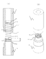
図4、図5は本発明の他の実施例を示すもので、この実施例においては前述の実施例の一方のフロート、この実施例においては密度フロート7の収容部材71’を、フロート7の下部の円筒状の凹部7bに埋め込んだものである。
4 and 5 show another embodiment of the present invention. In this embodiment, one of the floats of the above-described embodiment, in this embodiment, the accommodating member 71 'of the
そしてこの実施例においては各収容部材71’、81は、奥側に弾性部材を固定する複数の突起またはリブなどからなる弾性部材受け73,83が形成されており、弾性部材9はその端部をこれらの弾性部材受け73,83よりも奥側に押し込まれて抜けを防止されている。 また前述の実施例と同様に収容部の先端に内周面が対向する側が広くなるようにテーパ72、82が形成されている。
In this embodiment, each
この実施例によれば、一方の弾性部材収容部材71’をフロート7の内部に収容したので、フロート7の可動範囲を収容部材の長さL分だけ最小側に拡大することができ、密度の計測範囲を拡大できる。
According to this embodiment, since one elastic
図6(A)(B))は、それぞれ本発明の第三の実施例を示すもので、この実施例においては前述の第二実施例の外部に突出している収容部材81の先端にリブ84を、また他方の収容部材71の先端には収容部材81程度の長さ程度の突起74を形成し、その先端に抜け止め75が形成されている。
FIGS. 6 (A) and 6 (B) show a third embodiment of the present invention. In this embodiment, a
この実施例によれば突起74によりステムの軸線に垂直な方向の運動を制限するとともに、抜け止め75により2つのフロート7、8が大きく離間し過ぎて弾性部材9に変形が生じるのを防止できる。
また、フロート7とフロート8とが衝突しても弾性部材9が座屈するようなことがなく、永久変形するのを防止できる。
According to this embodiment, the
Further, even if the
1 地下タンク
3 ライザパイプ
4 液面検出装置
5 ステム
6 油面検出用フロート
7 密度フロート
8 水検出用フロート
9 弾性部材
M マグネット
DESCRIPTION OF
Claims (5)
Priority Applications (1)
| Application Number | Priority Date | Filing Date | Title |
|---|---|---|---|
| JP2011012440A JP5445477B2 (en) | 2011-01-25 | 2011-01-25 | Density measuring device |
Applications Claiming Priority (1)
| Application Number | Priority Date | Filing Date | Title |
|---|---|---|---|
| JP2011012440A JP5445477B2 (en) | 2011-01-25 | 2011-01-25 | Density measuring device |
Publications (2)
| Publication Number | Publication Date |
|---|---|
| JP2012154702A true JP2012154702A (en) | 2012-08-16 |
| JP5445477B2 JP5445477B2 (en) | 2014-03-19 |
Family
ID=46836591
Family Applications (1)
| Application Number | Title | Priority Date | Filing Date |
|---|---|---|---|
| JP2011012440A Active JP5445477B2 (en) | 2011-01-25 | 2011-01-25 | Density measuring device |
Country Status (1)
| Country | Link |
|---|---|
| JP (1) | JP5445477B2 (en) |
Cited By (3)
| Publication number | Priority date | Publication date | Assignee | Title |
|---|---|---|---|---|
| WO2014117666A1 (en) * | 2013-01-31 | 2014-08-07 | 张家港易化设备科技有限公司 | Dynamic and static oil-water separation apparatus and oil-water separation method |
| CN109764929A (en) * | 2019-03-14 | 2019-05-17 | 长沙学院 | A kind of piezoelectric type intelligence solution deep measuring device and measuring method |
| CN109764928A (en) * | 2019-03-14 | 2019-05-17 | 长沙学院 | A kind of measuring device and measuring method of strain-type intelligence solution deep and density |
Citations (5)
| Publication number | Priority date | Publication date | Assignee | Title |
|---|---|---|---|---|
| JPH01182753A (en) * | 1988-01-16 | 1989-07-20 | Shinji Kasai | Apparatus for measuring moisture in soil |
| US5253522A (en) * | 1991-07-11 | 1993-10-19 | Mts Systems Corporation | Apparatus for determining fluid level and fluid density |
| JP3307610B2 (en) * | 1999-06-23 | 2002-07-24 | 株式会社タツノ・メカトロニクス | Tank liquid level measurement device |
| JP2009525484A (en) * | 2006-01-30 | 2009-07-09 | フランクリン フューエリング システムズ インコーポレーテッド | Equipment for measuring liquid level and density |
| JP2009229377A (en) * | 2008-03-25 | 2009-10-08 | Showa Kiki Kogyo Co Ltd | Vibration-prevention structure of detection section of magnetostrictive liquid-level meter |
-
2011
- 2011-01-25 JP JP2011012440A patent/JP5445477B2/en active Active
Patent Citations (5)
| Publication number | Priority date | Publication date | Assignee | Title |
|---|---|---|---|---|
| JPH01182753A (en) * | 1988-01-16 | 1989-07-20 | Shinji Kasai | Apparatus for measuring moisture in soil |
| US5253522A (en) * | 1991-07-11 | 1993-10-19 | Mts Systems Corporation | Apparatus for determining fluid level and fluid density |
| JP3307610B2 (en) * | 1999-06-23 | 2002-07-24 | 株式会社タツノ・メカトロニクス | Tank liquid level measurement device |
| JP2009525484A (en) * | 2006-01-30 | 2009-07-09 | フランクリン フューエリング システムズ インコーポレーテッド | Equipment for measuring liquid level and density |
| JP2009229377A (en) * | 2008-03-25 | 2009-10-08 | Showa Kiki Kogyo Co Ltd | Vibration-prevention structure of detection section of magnetostrictive liquid-level meter |
Cited By (5)
| Publication number | Priority date | Publication date | Assignee | Title |
|---|---|---|---|---|
| WO2014117666A1 (en) * | 2013-01-31 | 2014-08-07 | 张家港易化设备科技有限公司 | Dynamic and static oil-water separation apparatus and oil-water separation method |
| CN109764929A (en) * | 2019-03-14 | 2019-05-17 | 长沙学院 | A kind of piezoelectric type intelligence solution deep measuring device and measuring method |
| CN109764928A (en) * | 2019-03-14 | 2019-05-17 | 长沙学院 | A kind of measuring device and measuring method of strain-type intelligence solution deep and density |
| CN109764929B (en) * | 2019-03-14 | 2023-10-13 | 长沙学院 | Piezoelectric intelligent solution depth measuring device and measuring method |
| CN109764928B (en) * | 2019-03-14 | 2023-10-13 | 长沙学院 | Device and method for measuring depth and density of strain type intelligent solution |
Also Published As
| Publication number | Publication date |
|---|---|
| JP5445477B2 (en) | 2014-03-19 |
Similar Documents
| Publication | Publication Date | Title |
|---|---|---|
| JP5257625B2 (en) | Liquid level measuring device with density measuring function | |
| JP5618187B2 (en) | Liquid level measuring device with density measuring function | |
| JP5445477B2 (en) | Density measuring device | |
| KR20060116734A (en) | Flowmeter | |
| JP2013015521A (en) | Fluid level sensor | |
| JP6013618B2 (en) | A device that measures the liquid level and specific gravity at the same time | |
| JP2013029337A (en) | Liquid level detection device | |
| JP3307610B2 (en) | Tank liquid level measurement device | |
| JP5995654B2 (en) | Float type liquid level sensor | |
| JP6109590B2 (en) | Flowmeter | |
| JP5986882B2 (en) | Float type level gauge | |
| JP2014085138A (en) | Liquid level detector | |
| JP4466461B2 (en) | Liquid level detector | |
| JP5669620B2 (en) | Liquid level detector | |
| JP5669621B2 (en) | Float and liquid level detector | |
| JP5529656B2 (en) | Liquid level detector | |
| JP2010197228A (en) | Inclination amount detection sensor | |
| RU2603948C1 (en) | Device and method for determining liquid density | |
| RU2580902C1 (en) | Acceleration limit sensor | |
| JP4058062B2 (en) | Float type magnetostrictive liquid level detector | |
| JP5621517B2 (en) | Liquid level detector | |
| JP6668225B2 (en) | Liquid level detector | |
| JP2016183905A (en) | Liquid level detection device | |
| KR20140005396U (en) | Apparatus for Measuring Level | |
| US11535228B2 (en) | Filling level sensing device |
Legal Events
| Date | Code | Title | Description |
|---|---|---|---|
| A621 | Written request for application examination |
Free format text: JAPANESE INTERMEDIATE CODE: A621 Effective date: 20130131 |
|
| A977 | Report on retrieval |
Free format text: JAPANESE INTERMEDIATE CODE: A971007 Effective date: 20131023 |
|
| A131 | Notification of reasons for refusal |
Free format text: JAPANESE INTERMEDIATE CODE: A131 Effective date: 20131028 |
|
| A521 | Written amendment |
Free format text: JAPANESE INTERMEDIATE CODE: A523 Effective date: 20131105 |
|
| TRDD | Decision of grant or rejection written | ||
| A01 | Written decision to grant a patent or to grant a registration (utility model) |
Free format text: JAPANESE INTERMEDIATE CODE: A01 Effective date: 20131126 |
|
| A61 | First payment of annual fees (during grant procedure) |
Free format text: JAPANESE INTERMEDIATE CODE: A61 Effective date: 20131209 |
|
| R150 | Certificate of patent or registration of utility model |
Ref document number: 5445477 Country of ref document: JP Free format text: JAPANESE INTERMEDIATE CODE: R150 Free format text: JAPANESE INTERMEDIATE CODE: R150 |