JP2012152180A - Paddy field working vehicle - Google Patents

Paddy field working vehicle Download PDF

Info

Publication number
JP2012152180A
JP2012152180A JP2011016076A JP2011016076A JP2012152180A JP 2012152180 A JP2012152180 A JP 2012152180A JP 2011016076 A JP2011016076 A JP 2011016076A JP 2011016076 A JP2011016076 A JP 2011016076A JP 2012152180 A JP2012152180 A JP 2012152180A
Authority
JP
Japan
Prior art keywords
fertilizer
remaining amount
discharge
amount
opening
Prior art date
Legal status (The legal status is an assumption and is not a legal conclusion. Google has not performed a legal analysis and makes no representation as to the accuracy of the status listed.)
Withdrawn
Application number
JP2011016076A
Other languages
Japanese (ja)
Inventor
Kazuhiko Ishii
和彦 石井
Manabu Takahashi
学 高橋
Yoshihiro Tai
義浩 田井
Current Assignee (The listed assignees may be inaccurate. Google has not performed a legal analysis and makes no representation or warranty as to the accuracy of the list.)
Iseki and Co Ltd
Iseki Agricultural Machinery Mfg Co Ltd
Original Assignee
Iseki and Co Ltd
Iseki Agricultural Machinery Mfg Co Ltd
Priority date (The priority date is an assumption and is not a legal conclusion. Google has not performed a legal analysis and makes no representation as to the accuracy of the date listed.)
Filing date
Publication date
Application filed by Iseki and Co Ltd, Iseki Agricultural Machinery Mfg Co Ltd filed Critical Iseki and Co Ltd
Priority to JP2011016076A priority Critical patent/JP2012152180A/en
Publication of JP2012152180A publication Critical patent/JP2012152180A/en
Withdrawn legal-status Critical Current

Links

Images

Classifications

    • YGENERAL TAGGING OF NEW TECHNOLOGICAL DEVELOPMENTS; GENERAL TAGGING OF CROSS-SECTIONAL TECHNOLOGIES SPANNING OVER SEVERAL SECTIONS OF THE IPC; TECHNICAL SUBJECTS COVERED BY FORMER USPC CROSS-REFERENCE ART COLLECTIONS [XRACs] AND DIGESTS
    • Y02TECHNOLOGIES OR APPLICATIONS FOR MITIGATION OR ADAPTATION AGAINST CLIMATE CHANGE
    • Y02PCLIMATE CHANGE MITIGATION TECHNOLOGIES IN THE PRODUCTION OR PROCESSING OF GOODS
    • Y02P60/00Technologies relating to agriculture, livestock or agroalimentary industries
    • Y02P60/12Technologies relating to agriculture, livestock or agroalimentary industries using renewable energies, e.g. solar water pumping

Abstract

PROBLEM TO BE SOLVED: To provide a paddy field working vehicle brought to be able to automatically discharge fertilizer remaining in the hopper of a fertilizing device to the outside.SOLUTION: The paddy field working vehicle includes a delivery device 61 for receiving the fertilizer from a fertilizer hopper 60 for storing the fertilizer and discharging a predetermined amount of the same to a farm field or the like and a blower 67 for blowing and conveying the fertilizer. In the vehicle, a freely rotative shutter 84 and a motor 111 for rotating the shutter 84 are installed to a fertilizer discharge port 83 for discharging the fertilizer from the fertilizer hopper 60 with facing a recovery part, and the vehicle is equipped with a control mechanism for bringing the wind power of the blower 67 to be stronger by increasing the shutter opening of the shutter 84 to be larger than a case when a controller 100 conveys the fertilizer to the delivery device 61 and also increasing the number of rotation of an engine, when an operation switch 112 for switching the fertilizer to move to either one of the delivery device 61 and the fertilizer discharge port 83 from the hopper 60 is operated to the side of fertilizer discharge.

Description

本発明は、施肥機や薬剤散布装置等の粉粒体繰出装置を備えた水田作業車両に関する。   The present invention relates to a paddy field work vehicle equipped with a granular material feeding device such as a fertilizer applicator or a chemical spraying device.

水田作業車両の粉粒体繰出装置は、粉粒体を貯めたホッパを備えている。粉粒体ホッパは、その上面を開閉する蓋を備え、該蓋を開けてホッパ内部に肥料や薬剤などの粉粒体を収納し、必要なときに外部に取り出して使用する。たとえば、粉粒体ホッパ内の粉粒体をその下側に設けた繰出部によって繰り出し、繰り出された粉粒体をエアチャンバから供給される加圧エアによって圃場まで搬送するようにした粉粒体繰出装置の一部として利用する。前記粉粒体繰出装置は田植機などに付属した施肥装置として用いることがある。
なお、本明細書では水田作業車両の操縦者が前進方向を向いて左右方向をそれぞれ左、右と言い、前進方向を前、後退方向を後と言うことにする。
The granular material feeding device of the paddy field work vehicle includes a hopper that stores the granular material. The powder hopper is provided with a lid that opens and closes its upper surface, and the lid is opened to store powder particles such as fertilizers and drugs in the hopper, and are taken out and used when necessary. For example, a granular material in which the granular material in the granular hopper is fed out by a feeding portion provided below, and the fed granular material is conveyed to the field by pressurized air supplied from an air chamber. Used as part of the feeding device. The granular material feeding device may be used as a fertilizer attached to a rice transplanter or the like.
In this specification, the operator of the paddy field work vehicle faces the forward direction, the left and right directions are respectively referred to as left and right, the forward direction is referred to as front, and the reverse direction is referred to as rear.

特開2006−166820号公報JP 2006-166820 A 特開2007−075059号公報Japanese Patent Laid-Open No. 2007-075059

上記特許文献1及び特許文献2の水田作業車両では、施肥装置のホッパに残った肥料を排出する際、肥料の移動経路を変更して排出することができるが、自動的にブロワの出力が変更されないため、肥料の排出量が少ないときには作業者がエンジン出力を変更する必要があり、作業者は排出作業中機体から離れられない問題がある。     In the paddy field work vehicle of the above-mentioned patent documents 1 and patent documents 2, when discharging the fertilizer remaining in the hopper of the fertilizer applicator, the fertilizer movement route can be changed and discharged, but the output of the blower is automatically changed. Therefore, when the amount of fertilizer discharged is small, the worker needs to change the engine output, and there is a problem that the worker cannot leave the machine body during the discharging work.

また、施肥ホッパに残る肥料の量が多い場合には、肥料の排出にかかる時間が長くなり、その分余分に燃料や電気を消費してしまう問題がある。
さらに、湿度が高い場合や、雨等の水がホッパ内に入り込む環境では、肥料が水分を吸収して大きな塊となり、肥料がホッパ内に詰まってしまい、作業者が手作業で肥料をホッパ内から取り除かねばならず、作業者の労力が増大する問題がある。
In addition, when the amount of fertilizer remaining in the fertilizer hopper is large, there is a problem that the time required for discharging the fertilizer becomes longer, and fuel and electricity are consumed in excess.
In addition, when the humidity is high or rain or other water enters the hopper, the fertilizer absorbs moisture and becomes a large lump, and the fertilizer is clogged in the hopper. There is a problem that the labor of the worker increases.

そこで、本発明の課題は、施肥装置のホッパに残った肥料を自動的に外部に排出することができるようにした水田作業車両を提供することである。   Then, the subject of this invention is providing the paddy field vehicle which enabled it to discharge | emit the fertilizer which remained in the hopper of the fertilizer applying apparatus automatically outside.

本発明の上記課題は、次の解決手段で解決される。
請求項1記載の発明は、回転数を変更自在なエンジン(20)と、エンジン(20)の回転数の変更を制御する制御装置(100)と、機体の後部に肥料を貯留する施肥貯留部(施肥ホッパ)(60)と、施肥貯留部(60)から肥料を受けて所定量ずつ圃場へ放出する繰出装置(61)と、繰出装置(61)から放出される肥料を搬送させる風を発生させる起風装置(施肥ブロワ)(67)で構成する圃場に肥料を供給する施肥装置(5)を設けた水田作業車両において、施肥貯留部(60)から肥料を排出するための肥料排出口(83)を繰出装置(61)から分岐して設け、該肥料排出口(83)には、該肥料排出口(83)の開度を変更する排出開閉板(84)を回動自在に設け、排出開閉板(84)を回動させて肥料の排出量を変更する排出切替駆動体(排出切替モータ)(111)と、施肥貯留部(60)から繰出装置(61)と肥料排出口(83)のどちらに肥料が移動するかを切り替える切替操作装置(112)を設け、切替操作装置(112)を肥料排出側に操作すると、制御装置(100)は繰出装置(61)へ肥料を搬送する場合より排出切替駆動体(111)による排出開閉板(84)の開度を大きくし、且つエンジン回転数を上げて起風装置(67)の風力を強くする制御構成を備えたことを特徴とする水田作業車両である。
The above-mentioned problem of the present invention is solved by the following means.
The invention according to claim 1 is an engine (20) whose rotation speed can be freely changed, a control device (100) for controlling change of the rotation speed of the engine (20), and a fertilizer storage section for storing fertilizer at the rear part of the fuselage. (Fertilizer hopper) (60), a feeding device (61) that receives fertilizer from the fertilizer storage section (60) and releases the fertilizer to the field by a predetermined amount, and generates a wind that conveys the fertilizer released from the feeding device (61) In a paddy field work vehicle provided with a fertilizer application device (5) for supplying fertilizer to a field composed of a wind-up device (fertilizer blower) (67) to be used, a fertilizer discharge port for discharging fertilizer from a fertilizer storage section (60) 83) is branched from the feeding device (61), and the fertilizer discharge port (83) is provided with a discharge opening / closing plate (84) for changing the opening of the fertilizer discharge port (83), Rotate the discharge opening / closing plate (84) to change the amount of fertilizer discharged And a switching operation device (112) for switching whether the fertilizer moves from the fertilizer storage section (60) to the feeding device (61) or the fertilizer discharge port (83). When the switching operation device (112) is operated to the fertilizer discharge side, the control device (100) is provided with the discharge opening / closing plate (84) by the discharge switching drive body (111) than when the fertilizer is conveyed to the feeding device (61). It is a paddy field work vehicle provided with the control structure which enlarges an opening degree and raises an engine speed, and strengthens the wind force of a wind generator (67).

請求項2記載の発明は、前記施肥貯留部(60)内に肥料の残量を検出する残量検知部材(肥料残量センサ)(113)を設け、切替操作装置(112)を肥料排出側に操作した際、前記制御装置(100)は、残量検知部材(113)が施肥貯留部(60)内での肥料残量が残量設定量の範囲にあることを検知すると、該残量検知部材(113)が施肥貯留部(60)内の肥料残量が残量設定量の範囲にないことを検知した場合に比べて、制御装置(100)はエンジン回転数を増加させて起風装置(67)の風力を強くすると共に、前記排出開閉板(84)の開度を大きくし、残量検知部材(113)が施肥貯留部(60)内の肥料残量が残量設定量の下限値未満になったことを検知すると、残量検知部材(113)が肥料残量が残量設定量の範囲にあることを検知する場合に比べてエンジン回転数を減少させて起風装置(67)の風力を弱めると共に、前記排出開閉板(84)の開度を小さくする制御構成を備えたことを特徴とする請求項1記載の水田作業車両である。   The invention according to claim 2 is provided with a remaining amount detection member (fertilizer remaining amount sensor) (113) for detecting the remaining amount of fertilizer in the fertilizer storage section (60), and the switching operation device (112) is disposed on the fertilizer discharge side. When the control device (100) detects that the remaining amount of fertilizer in the fertilizer storage section (60) is within the range of the remaining amount setting amount when the control device (100) is operated, Compared with the case where the detection member (113) detects that the remaining amount of fertilizer in the fertilizer storage part (60) is not within the range of the remaining amount setting amount, the control device (100) increases the engine speed and raises the wind. The wind force of the device (67) is strengthened, the opening degree of the discharge opening / closing plate (84) is increased, and the remaining amount detection member (113) is set to the remaining amount of fertilizer in the fertilizer storage part (60). When it is detected that the value is less than the lower limit, the remaining amount detecting member (113) sets the remaining amount of fertilizer. Compared to the case where it is detected that the amount is within the range, the engine speed is decreased to weaken the wind force of the wind-up device (67), and the control structure to reduce the opening degree of the discharge opening / closing plate (84) is provided. The paddy field work vehicle according to claim 1.

請求項3記載の発明は、残量検知部材(113)が、施肥貯留部(60)内の肥料残量が設定量の上限値を超えたことを検知すると、残量検知部材(113)が施肥貯留部(60)内の肥料残量が設定量の範囲にあることを検知する場合に比べて、制御装置(100)はエンジン回転数を減少させて起風装置(67)の風力を弱めると共に排出開閉板(84)の開度を小さくする制御構成を備えたことを特徴とする請求項2記載の水田作業車両である。   When the remaining amount detecting member (113) detects that the remaining amount of fertilizer in the fertilizer storage part (60) exceeds the upper limit value of the set amount, the remaining amount detecting member (113) Compared with the case where it is detected that the fertilizer remaining amount in the fertilizer storage part (60) is within the set amount range, the control device (100) decreases the engine speed and weakens the wind force of the wind generator (67). A paddy work vehicle according to claim 2, further comprising a control structure for reducing the opening degree of the discharge opening / closing plate (84).

請求項4記載の発明は、前記残量検知部材(113)が、施肥貯留部(60)内の肥料残量が設定量の範囲内にあることを検知すると作動するタイマー(114)と、該タイマー(114)で設定した排出時間が経過すると作動する報知手段(116)を設け、該報知手段(116)作動後の一定時間内に切替操作装置(肥料排出スイッチ)(112)を操作すると、制御装置(100)は前記排出開閉板(84)の開度を維持すると共に、報知手段(116)作動後の一定時間内に切替操作装置(112)が操作されないと、制御装置(100)は排出開閉板(排出シャッタ)(84)を閉じて肥料が出ない状態に切り替える制御構成としたことを特徴とする請求項2又は3に記載の水田作業車両である。   The invention according to claim 4 is characterized in that the remaining amount detecting member (113) operates when detecting that the remaining amount of fertilizer in the fertilizer storage section (60) is within a set amount range, When a notification means (116) that operates when the discharge time set by the timer (114) elapses is provided, and the switching operation device (fertilizer discharge switch) (112) is operated within a predetermined time after the notification means (116) is activated, The control device (100) maintains the opening degree of the discharge opening / closing plate (84), and if the switching operation device (112) is not operated within a certain time after the operation of the notification means (116), the control device (100) 4. The paddy field work vehicle according to claim 2, wherein the control structure is configured to close the discharge opening / closing plate (discharge shutter) and switch to a state in which no fertilizer is discharged.

請求項5記載の発明は、前記施肥貯留部(60)に肥料を受ける肥料受け部材(肥料受けマット)(117)を配置し、該肥料受け部材(117)の一端部を繰出装置(61)に接触させて配置したことを特徴とする請求項1記載の水田作業車両である。   According to the fifth aspect of the present invention, a fertilizer receiving member (fertilizer receiving mat) (117) for receiving fertilizer is disposed in the fertilizer storage section (60), and one end of the fertilizer receiving member (117) is fed out by a feeding device (61). The paddy field work vehicle according to claim 1, wherein the paddy field work vehicle is arranged in contact with the paddy field.

請求項1記載の発明によれば、切替操作装置112を肥料「排出」側に操作すると、施肥貯留部60に貯留された肥料が肥料排出口83側に移動し、排出開閉板84の開度が大きくなると共に、エンジン回転数が増加して起風装置67の風力が強くなる構成としたことにより、施肥装置5に残留する肥料を強風で肥料取出口83に移動させて高速で図示しない回収部に取り出すことができるので、肥料回収にかかる時間が短縮され、作業能率が向上する。
また、切替操作装置112を肥料「繰出」側に操作すると、従来通り圃場に所定量ずつ肥料を供給する施肥作業に切り替えることができる。
According to the first aspect of the present invention, when the switching operation device 112 is operated to the fertilizer “discharge” side, the fertilizer stored in the fertilizer storage section 60 moves to the fertilizer discharge port 83 side, and the opening degree of the discharge opening / closing plate 84 As the engine speed increases and the wind force of the wind raising device 67 increases, the fertilizer remaining in the fertilizer application device 5 is moved to the fertilizer outlet 83 by a strong wind and is not shown at high speed. Since it can be taken out to the part, the time taken for fertilizer recovery is shortened and the work efficiency is improved.
Further, when the switching operation device 112 is operated to the fertilizer “feeding” side, it is possible to switch to a fertilization work for supplying the fertilizer to the farm field by a predetermined amount as before.

請求項2記載の発明によれば、請求項1記載の発明の効果に加えて、施肥貯留部60内に肥料の残量を検出する残量検知部材113を設け、残量検知部材113が施肥貯留部60内での肥料設定量の範囲内の肥料量を検知すると、エンジン回転数を増加させて、起風装置67の風力を強くすると共に、排出開閉板84の開度が大きくなる構成としたことにより、施肥装置5に残留する肥料を高速で吹き飛ばして肥料取出口83から取り出すことができるので、施肥貯留部60からの肥料回収にかかる時間が短縮され、作業能率が向上する。   According to the invention described in claim 2, in addition to the effect of the invention described in claim 1, the remaining amount detection member 113 for detecting the remaining amount of fertilizer is provided in the fertilizer storage section 60, and the remaining amount detection member 113 is used as a fertilizer. When the fertilizer amount within the range of the fertilizer set amount in the storage unit 60 is detected, the engine speed is increased, the wind power of the wind generator 67 is increased, and the opening degree of the discharge opening / closing plate 84 is increased. As a result, the fertilizer remaining in the fertilizer application device 5 can be blown off at high speed and taken out from the fertilizer outlet 83. Therefore, the time required for fertilizer recovery from the fertilizer storage section 60 is shortened, and the work efficiency is improved.

そして、施肥貯留部60内の肥料残量が残量検知部材113の設定量下限値未満になると、エンジン回転数を減少させて起風装置67の風力を弱めると共に、排出切替駆動体111により排出開閉板84の開度が小さくなる構成としたことにより、残り少なくなった肥料を排出する際に余分なエンジン出力が必要無くなるため、燃料の節約になる。   When the remaining amount of fertilizer in the fertilizer storage section 60 becomes less than the set amount lower limit value of the remaining amount detection member 113, the engine speed is decreased to weaken the wind force of the wind generating device 67 and discharged by the discharge switching drive body 111. By adopting a configuration in which the opening degree of the opening / closing plate 84 is reduced, an extra engine output is not required when discharging the remaining less fertilizer, thereby saving fuel.

請求項3記載の発明によれば、請求項2記載の発明の効果に加えて、残量検知部材113が設定量上限値を超える量の肥料を検出すると、エンジン回転数を減少させて起風装置67の風力を弱めると共に、排出開閉板84の開度を小さくする制御構成としたことにより、施肥貯留部60から大量の肥料が肥料排出側の流路に送られて詰まってしまうことが防止されるので、肥料の排出作業が中断されることがなく作業能率が向上する。
また、作業者が詰まった肥料を除去する作業が不要となるため、作業者は他の作業を行うことができ、作業終了後の機体のメンテナンス性が向上する。
According to the invention of claim 3, in addition to the effect of the invention of claim 2, when the remaining amount detection member 113 detects fertilizer in an amount exceeding the upper limit of the set amount, the engine speed is reduced and the wind is raised. Since the wind power of the device 67 is weakened and the opening degree of the discharge opening / closing plate 84 is reduced, a large amount of fertilizer is prevented from being sent from the fertilizer storage part 60 to the flow path on the fertilizer discharge side and clogged. As a result, the work efficiency is improved without interrupting the fertilizer discharge operation.
In addition, since the operator does not need to remove the fertilizer clogged, the operator can perform other operations, and the maintainability of the machine body after the operation is improved.

請求項4記載の発明によれば、請求項2又は3記載の発明の効果に加えて、残量検知部材113が肥料設定量の範囲内の肥料量を検知するとタイマー114が作動し、このタイマー114に設定した時間が経過すると報知手段116が作動して所定時間が経過したことを作業者に知らせることができるので、作業者は施肥貯留部60からの肥料の排出中に他の作業をすることができ、作業終了後の機体のメンテナンス性やメンテナンス作業の能率が向上する。   According to the invention of claim 4, in addition to the effect of the invention of claim 2 or 3, when the remaining amount detecting member 113 detects the amount of fertilizer within the range of the fertilizer set amount, the timer 114 is activated, and this timer When the time set in 114 elapses, the notifying means 116 is activated to notify the operator that the predetermined time has elapsed, so that the operator performs other work while the fertilizer is discharged from the fertilizer storage section 60. Therefore, the maintainability of the airframe after the work is completed and the efficiency of the maintenance work are improved.

そして、報知手段116ヘの作動後、一定時間内に切替操作装置112を操作すると、排出開閉板84の開度が維持されるため、施肥貯留部60内の肥料残量が多い場合は肥料の排出量の再設定等を行うことなく肥料排出作業を継続することができるので、作業能率が向上する。   When the switching operation device 112 is operated within a certain time after the operation to the notification means 116, the opening degree of the discharge opening / closing plate 84 is maintained. Therefore, when the remaining amount of fertilizer in the fertilizer storage section 60 is large, the fertilizer Since the fertilizer discharge work can be continued without resetting the discharge amount, the work efficiency is improved.

さらに、一定時間内に切替操作装置112が操作されない場合、排出開閉板84を閉じて施肥貯留部60からの肥料排出を遮断することにより、作業者が休憩や他の作業をするために機体から離れた状態で一定時間が経過した場合、肥料の排出が完了すると排出開閉板84の開閉動作が行われなくなると共に、排出開閉板84が「閉」状態になった際に起風装置67が自動的に停止するので、電力の節約を図ることができる。   Further, when the switching operation device 112 is not operated within a certain period of time, the discharge opening / closing plate 84 is closed to shut off the fertilizer discharge from the fertilizer storage section 60, so that the operator can take a break or perform other work from the machine body. When a certain period of time has passed in the separated state, when the fertilizer is completely discharged, the opening / closing operation of the discharge opening / closing plate 84 is not performed, and the wind-up device 67 is automatically activated when the discharge opening / closing plate 84 is in the “closed” state. Therefore, power can be saved.

請求項5記載の発明によれば、請求項1記載の発明の効果に加えて、施肥貯留部60に肥料を受ける肥料受け部材117を設け、この肥料受け部材117の一端部を繰出装置61に接触させる配置にしたことにより、繰出装置61を回転させると肥料受け部材117を振動させることができるので、肥料が作業中に固まって移動しなくなることが防止され、肥料詰まりが防止される。   According to the invention described in claim 5, in addition to the effect of the invention described in claim 1, the fertilizer receiving member 117 that receives fertilizer is provided in the fertilizer storage portion 60, and one end of the fertilizer receiving member 117 is provided in the feeding device 61. When the feeding device 61 is rotated by virtue of the arrangement of contact, the fertilizer receiving member 117 can be vibrated, so that it is prevented that the fertilizer becomes hard during operation and does not move, and the fertilizer clogging is prevented.

本発明の実施例の施肥装置付き乗用型田植機の側面図である。It is a side view of the riding type rice transplanter with a fertilizer application of the example of the present invention. 図1の施肥装置付き乗用型田植機の平面図である。It is a top view of the riding type rice transplanter with a fertilizer application of FIG. 図1の施肥装置の背面図である。It is a rear view of the fertilizer application of FIG. 図1の施肥装置の平面図である。It is a top view of the fertilizer application of FIG. 図1の施肥装置の側面図である。It is a side view of the fertilizer application of FIG. 図1の施肥装置の粉粒体繰出部の側面断面図である。It is side surface sectional drawing of the granular material supply part of the fertilizer application of FIG. 図1の施肥装置の粉粒体繰出部の変形例の側面断面図である。It is side surface sectional drawing of the modification of the granular material supply part of the fertilizer application of FIG. 図6のS−S断面図である。It is SS sectional drawing of FIG. 図1の苗移植機の制御装置のブロック図である。It is a block diagram of the control apparatus of the seedling transplanter of FIG. 図1の苗移植機の肥料ホッパの内部側壁に配置した肥料残量センサと該センサによる設定された肥料充填量の範囲を示す図である。It is a figure which shows the range of the fertilizer filling amount set by the fertilizer residual amount sensor arrange | positioned in the internal side wall of the fertilizer hopper of the seedling transplanter of FIG. 1, and this sensor. 図1の苗移植機の排出切替モータのシャッタの作動機構部を示す図である。It is a figure which shows the action | operation mechanism part of the shutter of the discharge switching motor of the seedling transplanter of FIG. 図1の苗移植機の肥料ホッパ内の肥料センサの構成を示す斜視図(図12(a))とフロート付きのアームの構造図(図12(b))である。They are a perspective view (Drawing 12 (a)) which shows composition of a manure sensor in a manure hopper of a seedling transplanter of Drawing 1, and a structural diagram (Drawing 12 (b)) of an arm with a float. 図1の苗移植機の施肥ホースの内部構造図(図13a))とピースの斜視図(図13(b))と従来技術の施肥ホースの内部構造図(図13(c))である。FIG. 13 is an internal structure diagram (FIG. 13 a) of a fertilization hose of the seedling transplanter of FIG. 1, a perspective view of a piece (FIG. 13 b), and an internal structure diagram of a conventional fertilization hose (FIG. 13 c). 図1の苗移植機の施肥ホースのチューブ差込タイプの内部構造図(図14(a))と従来技術のチューブ差込タイプの内部構造図(図14(b))である。It is the internal structure figure (Fig.14 (a)) of the tube insertion type of the fertilization hose of the seedling transplanter of FIG. 1, and the internal structure figure (FIG.14 (b)) of the tube insertion type of a prior art. 図1の苗移植機として太陽光を利用するタイプの田植機の側面図(図15(a))と主要部の背面図(図15(b))である。It is the side view (FIG. 15 (a)) of the rice transplanter of the type which uses sunlight as a seedling transplanter of FIG. 1, and the rear view (FIG.15 (b)) of the principal part. 図1の苗移植機の予備苗載台支持枠の機体内側にパラソル立てを取り付けた場合の要部構造図である。It is a principal part structure figure at the time of attaching the parasol stand to the inner side of the body of the preliminary seedling support frame of the seedling transplanter of FIG. 苗移植機の予備苗載台支持枠の機体内側にパラソル立てを取り付けた場合の側面図である。It is a side view at the time of attaching the parasol stand inside the body of the preliminary seedling support stand of a seedling transplanter. 図1の苗移植機のリンクベースフレームにパラソル立てを設ける構成を示す説明図である。It is explanatory drawing which shows the structure which provides a parasol stand in the link base frame of the seedling transplanter of FIG. 苗移植機の予備苗載台支持枠の機体内側にパラソル立てを取り付けた場合の側面図である。It is a side view at the time of attaching the parasol stand inside the body of the preliminary seedling support stand of a seedling transplanter.

以下、図面に基づき、本発明の好ましい実施の形態について説明する。
図1及び図2は本発明を用いた一実施例である粉粒体繰出装置を有する施肥装置を装着した施肥装置付き乗用型田植機を表している。この施肥装置付き乗用型田植機1は、走行車体2の後側に昇降リンク装置3を介して苗植付部4が昇降可能に装着され、走行車体2の後部上側に施肥装置5の本体部分が設けられている。
Hereinafter, preferred embodiments of the present invention will be described with reference to the drawings.
FIG.1 and FIG.2 represents the riding type rice transplanter with a fertilizer applicator equipped with the fertilizer applicator which has a granular material feeding apparatus which is one Example using this invention. In this riding type rice transplanter 1 with a fertilizer application, a seedling planting portion 4 is mounted on the rear side of the traveling vehicle body 2 via an elevating link device 3 so that the seedling planting portion 4 can be moved up and down. Is provided.

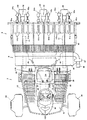
走行車体2は、駆動輪である左右一対の前輪10,10及び左右一対の後輪11,11を備えた四輪駆動車両であって、機体の前部にミッションケース12が配置され、そのミッションケース12の左右側方に前輪ファイナルケース13,13が設けられ、該左右前輪ファイナルケース13,13の操向方向を変更可能な各々の前輪支持部から外向きに突出する左右前輪車軸に左右前輪10,10が各々取り付けられている。また、ミッションケース12の背面部にメインフレーム15の前端部が固着されており、そのメインフレーム15の後端左右中央部に前後水平に設けた後輪ローリング軸を支点にして後輪ギヤケース18,18がローリング自在に支持され、その後輪ギヤケース18,18から外向きに突出する後輪車軸に後輪11,11が取り付けられている。   The traveling vehicle body 2 is a four-wheel drive vehicle including a pair of left and right front wheels 10 and 10 and a pair of left and right rear wheels 11 and 11 as drive wheels, and a transmission case 12 is disposed at the front of the fuselage. Front wheel final cases 13, 13 are provided on the left and right sides of the case 12, and the left and right front wheels are mounted on the left and right front wheel axles projecting outward from the respective front wheel support portions capable of changing the steering direction of the left and right front wheel final cases 13, 13. 10 and 10 are respectively attached. Further, the front end portion of the main frame 15 is fixed to the rear portion of the transmission case 12, and a rear wheel gear case 18, with a rear wheel rolling shaft provided horizontally in the front and rear sides at the rear left and right center of the main frame 15 as a fulcrum. The rear wheels 11 and 11 are attached to a rear wheel axle that is supported in a freely rolling manner and projects outwardly from the rear wheel gear cases 18 and 18.

エンジン20はメインフレーム15の上に搭載されており、該エンジン20の回転動力が、第一ベルト伝動装置21及びHST23を介してミッションケース12に伝達される。ミッションケース12に伝達された回転動力は、該ケース12内のトランスミッションにより変速された後、走行動力と外部取出動力に分離して取り出される。そして、走行動力は、一部が前輪ファイナルケース13,13に伝達されて前輪10,10を駆動すると共に、残りが後輪ギヤケース18,18に伝達されて後輪11,11を駆動する。また、外部取出動力は、走行車体2の後部に設けた植付クラッチケース25に伝達され、それから植付伝動軸26によって苗植付部4へ伝動されるとともに、施肥伝動機構27によって施肥装置5へ伝動される。   The engine 20 is mounted on the main frame 15, and the rotational power of the engine 20 is transmitted to the transmission case 12 via the first belt transmission device 21 and the HST 23. The rotational power transmitted to the mission case 12 is shifted by a transmission in the case 12 and then separated into traveling power and external power to be extracted. A part of the traveling power is transmitted to the front wheel final cases 13 and 13 to drive the front wheels 10 and 10, and the rest is transmitted to the rear wheel gear cases 18 and 18 to drive the rear wheels 11 and 11. Further, the external take-out power is transmitted to a planting clutch case 25 provided at the rear part of the traveling vehicle body 2, and then transmitted to the seedling planting unit 4 by the planting transmission shaft 26, and also the fertilizer application device 5 by the fertilization transmission mechanism 27. Is transmitted to.

エンジン20の上部はエンジンカバー30で覆われており、その上に座席31が設置されている。座席31の前方には各種操作機構を内蔵するフロントカバー32があり、その上方に前輪10,10を操向操作するハンドル34が設けられている。エンジンカバー30及びフロントカバー32の下端左右両側は水平状のフロアステップ35になっている。フロアステップ35は一部格子状になっており(図2参照)、該ステップ35を歩く作業者の靴についた泥が圃場に落下するようになっている。フロアステップ35上の後部は、後輪フェンダを兼ねるリヤステップ36となっている。
また、走行車体2の前部左右両側には、補給用の苗を載せておく予備苗載台38,38が機体よりも側方に張り出す位置と内側に収納した位置とに回動可能に設けられている。
The upper part of the engine 20 is covered with an engine cover 30, and a seat 31 is installed thereon. A front cover 32 incorporating various operation mechanisms is provided in front of the seat 31, and a handle 34 for steering the front wheels 10 and 10 is provided above the front cover 32. The engine cover 30 and the front cover 32 have horizontal floor steps 35 on the left and right sides of the lower end. The floor step 35 is partly grid-shaped (see FIG. 2), and mud on the shoe of the worker walking through the step 35 falls on the field. The rear part on the floor step 35 is a rear step 36 that also serves as a rear wheel fender.
Further, on both the left and right sides of the front part of the traveling vehicle body 2, the spare seedling platforms 38, 38 on which the replenishment seedlings are placed can be pivoted to a position projecting laterally from the machine body and a position housed inside. Is provided.

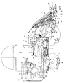
昇降リンク装置3は平行リンク構成であって、1本の上リンク40と左右一対の下リンク41,41を備えている。これらリンク40,41,41は、その基部側がメインフレーム15の後端部に立設した背面視門形のリンクベースフレーム42に回動自在に取り付けられ、その先端側に縦リンク43が連結されている。そして、縦リンク43の下端部に苗植付部4に回転自在に支承された連結軸44が挿入連結され、連結軸44を中心として苗植付部4がローリング自在に連結されている。メインフレーム15に固着した支持部材と上リンク40に一体形成したスイングアーム45の先端部との間に昇降油圧シリンダ46が設けられており、該シリンダを油圧で伸縮させることにより、上リンク40が上下に回動し、苗植付部4がほぼ一定姿勢のまま昇降する。   The elevating link device 3 has a parallel link configuration, and includes one upper link 40 and a pair of left and right lower links 41, 41. These links 40, 41, 41 are pivotally attached to a rear-view portal-shaped link base frame 42 erected on the rear end of the main frame 15, and a vertical link 43 is connected to the tip side thereof. ing. And the connecting shaft 44 rotatably supported by the seedling planting part 4 is inserted and connected to the lower end part of the vertical link 43, and the seedling planting part 4 is connected so as to be able to roll around the connecting shaft 44. An elevating hydraulic cylinder 46 is provided between a support member fixed to the main frame 15 and a tip of a swing arm 45 formed integrally with the upper link 40, and the upper link 40 is expanded and contracted by hydraulically extending the cylinder. It rotates up and down and the seedling planting part 4 moves up and down while maintaining a substantially constant posture.

苗植付部4は6条植の構成で、フレームを兼ねる伝動ケース50、マット苗を載せて左右往復動し苗を一株分ずつ各条の苗取出口51a,…に供給するとともに横一列分の苗を全て苗取出口51a,…に供給すると苗送りベルト51b,…により苗を下方に移送する苗載台51、苗取出口51a,…に供給された苗を苗植付具52aで圃場に植付ける苗植付装置52,…、次行程における機体進路を表土面に線引きする左右一対の線引きマーカ(図示せず)等を備えている。苗植付部4の下部には中央にセンターフロート55、その左右両側にサイドフロート56,56がそれぞれ設けられている。これらフロート55,56,56を圃場の泥面に接地させた状態で機体を進行させると、フロート55,56,56が泥面を整地しつつ滑走し、その整地跡に苗植付装置52,…により苗が植え付けられる。各フロート55,56,56は圃場表土面の凹凸に応じて前端側が上下動するように回動自在に取り付けられており、植付作業時にはセンターフロート55の前部の上下動が上下動検出機構57により検出され、その検出結果に応じ前記昇降油圧シリンダ46を制御する油圧バルブを切り替えて苗植付部4を昇降させることにより、苗の植付深さを常に一定に維持する。   The seedling planting section 4 has a six-row planting structure, a transmission case 50 that also serves as a frame, a mat seedling, and a left and right reciprocating motion to supply seedlings one by one to the seedling outlets 51a,. When all the seedlings are supplied to the seedling outlet 51a,..., The seedling mount 51 for transferring the seedling downward by the seedling feeding belt 51b,..., And the seedling supplied to the seedling outlet 51a,. A seedling planting device 52 to be planted in a farm field, and a pair of left and right drawing markers (not shown) for drawing the aircraft path in the next stroke to the topsoil surface are provided. In the lower part of the seedling planting part 4, a center float 55 is provided in the center, and side floats 56, 56 are provided on the left and right sides thereof. When the aircraft is advanced with these floats 55, 56, 56 in contact with the mud surface of the field, the floats 55, 56, 56 slide while leveling the mud surface, and the seedling planting device 52, ... to plant seedlings. Each of the floats 55, 56, and 56 is pivotally attached so that the front end side moves up and down according to the unevenness of the field topsoil surface, and the vertical movement of the front part of the center float 55 is detected as a vertical movement detection mechanism during planting work. The planting depth of the seedling is always maintained constant by switching the hydraulic valve that controls the lifting hydraulic cylinder 46 according to the detection result to raise and lower the seedling planting unit 4.

また、上記センターフロート55及び左右のサイドフロート56,56の前側に、回転しながら圃場面に接触し、苗の植付位置の周辺を平坦に整地する整地ロータ24を設ける。該整地ロータ24は、前記センターフロート55の前方を整地するセンターロータ24aと、前記左右のサイドフロート56,56の前方を整地する左右のサイドロータ24b,24bで構成する。   Further, on the front side of the center float 55 and the left and right side floats 56, 56, a leveling rotor 24 is provided that contacts the field scene while rotating and levels the periphery of the seedling planting position. The leveling rotor 24 includes a center rotor 24a for leveling the front of the center float 55 and left and right side rotors 24b, 24b for leveling the front of the left and right side floats 56, 56.

なお、整地ロータ24は、上下位置調節機構(図示省略)により、作業者が圃場の深さや固さ等の作業条件に合わせて上下位置を調節可能に構成すると、圃場面への整地ロータ24、即ちセンターロータ24aと左右のサイドロータ24b,24bがしっかりと圃場に接地して圃場面の凹凸を平坦に均すことができるので、苗の植付深さが一定に揃い、苗の生育が安定する。   The leveling rotor 24 is configured so that the vertical position adjustment mechanism (not shown) allows the operator to adjust the vertical position according to work conditions such as the depth and hardness of the farm field. That is, since the center rotor 24a and the left and right side rotors 24b, 24b can be securely grounded to the field and the unevenness of the field can be leveled, the planting depth of the seedling is uniform and the growth of the seedling is stable. To do.

一方、圃場の土質が柔らかい場合は、整地ロータ24を若干上方に移動させて圃場面への接触を弱くすることにより、泥土が整地ロータ24の回転に巻き込まれて水に溶け込み、泥水流となって植え付けられた苗を押し流したり、植付軌跡を視認しにくくすることを防止できるので、苗を植え直す必要が無く作業者の労力が軽減されると共に、作業者が植付軌跡を随時視認しやすくなり、植付列の歪みを抑えて植付精度を高めることができる。   On the other hand, when the soil quality is soft, the soil leveling rotor 24 is moved slightly upward to weaken the contact with the field scene, so that the mud is caught in the rotation of the leveling rotor 24 and melts into the water, resulting in a muddy water flow. This prevents the planted seedlings from being swept away and making it difficult to see the planting trajectory, reducing the labor of the operator without having to replant the seedling, and allowing the worker to view the planting trajectory from time to time. It becomes easy and can suppress the distortion of the planting row and increase the planting accuracy.

前記センターロータ24a及び左右のサイドロータ24b,24bの上部には、回転により泥土や水が植付部4の各部材に飛散することを防止するロータカバー24cがそれぞれ配置されている。   A rotor cover 24c that prevents mud and water from splashing on each member of the planting part 4 due to rotation is disposed on the center rotor 24a and the left and right side rotors 24b and 24b.

施肥装置5は、肥料ホッパ60に貯留されている粒状の肥料を繰出部61,…によって一定量ずつ繰り出し、その肥料を施肥ホース62,…でセンターフロート55及びサイドフロート56,56の左右両側に取り付けた施肥ガイド63,…まで導き、施肥ガイド63,…の前側に設けた作溝体64,…によって苗植付条の側部近傍に形成される施肥構内に落とし込むようになっている。電動モータ66で駆動のブロア67で発生させたエアが、左右方向に長いエアチャンバ68を経由して施肥ホース62,…に吹き込まれ、施肥ホース62,…内の肥料を風圧で強制的に搬送するようになっている。   The fertilizer applicator 5 feeds the granular fertilizer stored in the fertilizer hopper 60 by a fixed amount by the feeding sections 61,... And the fertilizer is fed to the left and right sides of the center float 55 and the side floats 56, 56 by the fertilizer hose 62,. It guide | induces to the installed fertilizer guide 63, ..., and it drops in the fertilizer structure formed in the side part vicinity of a seedling planting row | line | column by the groove body 64, ... provided in the front side of the fertilizer guide 63, .... The air generated by the blower 67 driven by the electric motor 66 is blown into the fertilizer hose 62,... Via the air chamber 68 that is long in the left-right direction, and the fertilizer in the fertilizer hose 62,. It is supposed to be.

以下、図3〜図14に示す施肥装置5の各部の構成について説明する。
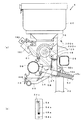
肥料ホッパ60は各条共用で、上部に開閉可能な蓋60aが取り付けられている。肥料ホッパ60の下部は施肥条数分に分岐して漏斗状になっており、その下部が繰出部61、…の上端に接続されている。肥料ホッパ60は、左右方向に長い施肥装置側フレーム49に支持された左右2箇所の回動アーム71に取り付けられていて、この回動アーム71の下端部を支点に後方に回動させて繰出部61,…から分離させられるようになっている。回動アーム71は外側から1条目の繰出部と2条目の繰出部との間に配置されている(左右対称位置に2つ設けられている)。肥料ホッパ60の下部を肥料繰出部61,…の上端に接続した通常位置では、係止具72により肥料ホッパ60を固定しておく。
Hereinafter, the structure of each part of the fertilizer applicator 5 shown in FIGS. 3-14 is demonstrated.
The fertilizer hopper 60 is shared by each strip, and a lid 60a that can be opened and closed is attached to the top. The lower part of the fertilizer hopper 60 is branched into the number of fertilizer strips and has a funnel shape, and the lower part is connected to the upper ends of the feeding parts 61. The fertilizer hopper 60 is attached to two left and right rotating arms 71 supported by a fertilizer application side frame 49 that is long in the left-right direction. It can be separated from the parts 61. The rotating arm 71 is disposed between the first feeding portion and the second feeding portion from the outside (two are provided at symmetrical positions). At the normal position where the lower part of the fertilizer hopper 60 is connected to the upper ends of the fertilizer feeding parts 61,...

図6、図8に示すように繰出部61は、肥料ホッパ60内の肥料を下方に繰り出す2個の繰出ロール73A,73Bを内蔵している。これらの繰出ロール73A,73Bは、外周部に溝状の凹部74,…が形成された回転体で、左右方向に設けた共通の繰出軸75の角軸部75a(図示例は四角軸)にそれぞれ一体回転するように嵌合している。繰出ロール73A,73Bが図6の矢印方向に回転することにより、肥料ホッパ60から落下供給される肥料が凹部74に収容されて下方に繰り出される。両繰出ロール73A,73Bにより繰り出された肥料は、下端の吐出口61aから吐出される。   As shown in FIGS. 6 and 8, the feeding unit 61 includes two feeding rolls 73 </ b> A and 73 </ b> B that feed the fertilizer in the fertilizer hopper 60 downward. These feeding rolls 73A, 73B are rotating bodies having groove-shaped recesses 74,... Formed on the outer peripheral portion thereof, and are provided on a corner shaft portion 75a (square shaft in the illustrated example) of a common feeding shaft 75 provided in the left-right direction. They are fitted so as to rotate together. As the feed rolls 73A and 73B rotate in the direction of the arrow in FIG. 6, the fertilizer dropped and supplied from the fertilizer hopper 60 is accommodated in the recess 74 and fed downward. The fertilizer fed out by both the feeding rolls 73A and 73B is discharged from the discharge port 61a at the lower end.

図示例の繰出ロール73A,73Bの凹部74の数は6個であり、両者の凹部の位相を異ならせてある。このため、両繰出ロール73A,73Bの凹部74が交互に肥料を繰り出すこととなり、吐出口61aから吐出される肥料の量が時間的に均等化されている。いずれかの繰出ロール73A又は73Bを繰出軸75から外して位相を適当に変更して付け直すことにより、両繰出ロール73A,73Bの凹部74の位相を等しくすることもできる。これで、圃場に点状に肥料を散布する場合に適用可能となる。   The number of the concave portions 74 of the feeding rolls 73A and 73B in the illustrated example is six, and the phases of the concave portions are different from each other. For this reason, the concave portions 74 of the feeding rolls 73A and 73B alternately feed the fertilizer, and the amount of the fertilizer discharged from the discharge port 61a is equalized in terms of time. The phase of the concave portions 74 of both the feeding rolls 73A and 73B can be made equal by removing any one of the feeding rolls 73A or 73B from the feeding shaft 75 and changing the phase appropriately. This makes it possible to apply fertilizer to the field in the form of dots.

また、繰出部61の内部には、凹部74が下方に移動する側(前側)の繰出ロール73の外周面に摺接するブラシ76が着脱自在に設けられている。このブラシ76によって繰出ロール73A,73Bの凹部74に肥料が摺り切り状態で収容され、繰出ロール73A,73Bによる肥料繰出量が一定に保たれる。
また、肥料詰まり時の繰出ロール73とカプセル摩耗防止板82の下部接触部分(S)を図7に示すように鈍角状に接触する構成すると、繰出駆動ギヤ108aと繰出従動ギヤ108b(図5)の破損が防止できる。
In addition, a brush 76 slidably in contact with the outer peripheral surface of the feeding roll 73 on the side (front side) where the concave portion 74 moves downward is detachably provided inside the feeding portion 61. The fertilizer is housed in the recesses 74 of the feeding rolls 73A and 73B by the brush 76 in a state of being scraped, and the amount of fertilizer fed by the feeding rolls 73A and 73B is kept constant.
Further, when the feed roller 73 and the lower contact portion (S) of the capsule wear prevention plate 82 at the time of fertilizer clogging are configured to contact at an obtuse angle as shown in FIG. 7, the feed drive gear 108a and the feed driven gear 108b (FIG. 5). Can be prevented from being damaged.

さらに、ブラシ76の上側には、繰出ロール73A,73Bの上方に突出して肥料ホッパ60から繰出部61に肥料が落下供給されないようにする繰出停止シャッタ77A,77B(図8)が設けられている。繰出停止シャッタ77A,77Bは、繰出部ケース78のスライド支持部79(図6)にスライド自在に支持されていて、ケース外の前端部に形成された把手77aをつかんでスライドさせるようになっている。   Further, on the upper side of the brush 76, feeding stop shutters 77A and 77B (FIG. 8) are provided so as to prevent the fertilizer from dropping from the fertilizer hopper 60 to the feeding portion 61 so as to protrude above the feeding rolls 73A and 73B. . The feeding stop shutters 77A and 77B are slidably supported by a slide support portion 79 (FIG. 6) of the feeding portion case 78, and are slid by grasping a handle 77a formed at the front end portion outside the case. Yes.

繰出部61の吐出口61aには、前後方向に連通する接続管80(図3)が接続されている。そして、この接続管80の後端部に施肥ホース62(図5)が接続されている。施肥ホース62の外周螺旋溝に施肥装置側フレーム49(図5)の下端部が係合しているので、施肥ホース62が接続管80から抜けにくい。一方、各条の接続管80の前端部はエアチャンバ68(図4、図5)の背面部に挿入連結されている。エアチャンバ68の左端部はエア切替管81を介してブロア67(図3、図4)に接続されており、該ブロア67からのエアがエアチャンバ68を経由し接続管80から施肥ホース62に吹き込まれるようになっている。なお、ブロア67は、そのエア吐出口をエア切替管81から外して機体内方に回動収納できる構成としている。   A connecting pipe 80 (FIG. 3) communicating in the front-rear direction is connected to the discharge port 61 a of the feeding portion 61. A fertilizer hose 62 (FIG. 5) is connected to the rear end of the connection pipe 80. Since the lower end portion of the fertilizer application side frame 49 (FIG. 5) is engaged with the outer peripheral spiral groove of the fertilizer hose 62, the fertilizer hose 62 is difficult to come off from the connection pipe 80. On the other hand, the front end portion of each connecting pipe 80 is inserted and connected to the back surface portion of the air chamber 68 (FIGS. 4 and 5). The left end of the air chamber 68 is connected to a blower 67 (FIGS. 3 and 4) via an air switching pipe 81, and the air from the blower 67 passes from the connection pipe 80 to the fertilizer hose 62 via the air chamber 68. It comes to be blown. Note that the blower 67 is configured such that its air discharge port can be removed from the air switching pipe 81 and rotated and housed inside the machine body.

エアチャンバ68は、接続管80が取り付けられたゴム管68aと、中間部分の樹脂管68bとを交互に繋ぎ合わせて構成されている。この構成とすると、エアチャンバ68を簡単に分解、組み立てできるので、繰出部61を一体的に取り外してのメンテナンスが容易である。ゴム管68aの長さを一対の繰出部の間隔よりも長くしておくと、樹脂管68bからゴム管68aを抜きやすい。   The air chamber 68 is configured by alternately connecting a rubber pipe 68a to which a connecting pipe 80 is attached and a resin pipe 68b at an intermediate portion. With this configuration, the air chamber 68 can be easily disassembled and assembled, so that the maintenance with the feeding portion 61 removed as a whole is easy. If the length of the rubber tube 68a is made longer than the distance between the pair of feeding portions, the rubber tube 68a can be easily removed from the resin tube 68b.

また、図6に示すように、繰出部ケース78の背面部には、肥料ホッパ60内の肥料を取り出すための肥料排出口83が形成されている。この肥料排出口83には、上端側を支点にして開閉自在な排出シャッタ84が取り付けられている。各繰出部61の肥料排出口83は、繰出部61の後方に設けた左右方向に長い肥料回収管85に接続されている。肥料回収管85の左端部は、前記エア切替管81を介してブロア67に接続されている。エア切替管81は二股状の管であって、一方にエアチャンバ68が接続され、他方に肥料回収管85が接続されている。エア切替管81にはエア切替部としてのエア切替シャッタ86が設けられ、ブロア67から吹き出されるエアをエアチャンバ68側に供給する状態と肥料回収管85側に供給する状態とに切り替えられようになっている。エア切替シャッタ86はエアチャンバ68と肥料回収管85の間の前後中央部にあるので、両者へのエア供給が安定している。肥料回収管85の右端部は肥料回収口87になっている。   Further, as shown in FIG. 6, a fertilizer discharge port 83 for taking out the fertilizer in the fertilizer hopper 60 is formed on the back surface portion of the feeding portion case 78. The fertilizer discharge port 83 is provided with a discharge shutter 84 that can be opened and closed with the upper end side as a fulcrum. The fertilizer discharge port 83 of each feeding part 61 is connected to a fertilizer collecting pipe 85 that is provided in the rear of the feeding part 61 and that is long in the left-right direction. The left end portion of the fertilizer collection pipe 85 is connected to the blower 67 through the air switching pipe 81. The air switching pipe 81 is a bifurcated pipe, and an air chamber 68 is connected to one side and a fertilizer collection pipe 85 is connected to the other side. The air switching pipe 81 is provided with an air switching shutter 86 as an air switching section, and can be switched between a state where air blown from the blower 67 is supplied to the air chamber 68 side and a state where air is supplied to the fertilizer recovery pipe 85 side. It has become. Since the air switching shutter 86 is located in the front and rear central portion between the air chamber 68 and the fertilizer collecting pipe 85, the air supply to both is stable. The right end portion of the fertilizer collection pipe 85 is a fertilizer collection port 87.

本発明の制御ブロック図を図9に示す。
また、図10に示すように、肥料ホッパ60の内部側壁に肥料残量センサ113を配置し、肥料ホッパ60内の肥料に該センサ113に接触する位置を検知することで、肥料ホッパ60内の肥料残量を常に把握しておく。
A control block diagram of the present invention is shown in FIG.
Further, as shown in FIG. 10, a fertilizer remaining amount sensor 113 is arranged on the inner side wall of the fertilizer hopper 60, and the position of the fertilizer in the fertilizer hopper 60 contacting the sensor 113 is detected, so that Keep track of the remaining fertilizer.

また、肥料残量センサ113は肥料ホッパ60の内部側壁の上下方向に配置した複数の接触センサ113で構成してもよく、この場合は肥料ホッパ60内の肥料に接触している該センサ113の中で一番高い位置にあるセンサ113により肥料ホッパ60内での肥料の充填量が分かる。   Further, the fertilizer remaining amount sensor 113 may be constituted by a plurality of contact sensors 113 arranged in the vertical direction of the inner side wall of the fertilizer hopper 60, and in this case, the sensor 113 that is in contact with the fertilizer in the fertilizer hopper 60. The amount of fertilizer filled in the fertilizer hopper 60 can be determined by the sensor 113 at the highest position.

また、座席31の近傍には肥料排出スイッチ112を配置しておき、該スイッチ112が押されるとシャッタ84を回動させて肥料の排出量を変更する肥料排出モータ111が作動して、肥料の流路(排出口)83の開度を肥料排出量に応じて開く。該シャッタ84の開閉は図示しない手動レバーで行うこともできるが、ここではコントローラ100により作動制御される電動式の肥料排出モータ111(図11)で行う。また、そのときシャッタ84の開閉度合いに応じてブロア67も同時に作動開始する。該ブロア67の作動動力はエンジン回転数で調整する。   In addition, a fertilizer discharge switch 112 is arranged near the seat 31, and when the switch 112 is pressed, a fertilizer discharge motor 111 that rotates the shutter 84 to change the discharge amount of the fertilizer is operated, and the fertilizer is discharged. The opening degree of the flow path (discharge port) 83 is opened according to the fertilizer discharge amount. The shutter 84 can be opened and closed by a manual lever (not shown), but here, it is operated by an electric fertilizer discharge motor 111 (FIG. 11) that is controlled by the controller 100. At that time, the blower 67 also starts to operate simultaneously in accordance with the degree of opening and closing of the shutter 84. The operating power of the blower 67 is adjusted by the engine speed.

電動式の肥料排出モータ111によるシャッタ84の作動機構部は図11に示すように該モータ111に設けられたギヤ120と噛合するギヤ121aと一体のシャッタ開閉板121が回転軸121bを中心に作動することでシャッタ84の開閉度合いが決まる。   As shown in FIG. 11, the operating mechanism of the shutter 84 by the electric fertilizer discharge motor 111 is operated with a shutter opening / closing plate 121 integrated with a gear 121a meshing with a gear 120 provided in the motor 111 about a rotating shaft 121b. As a result, the degree of opening and closing of the shutter 84 is determined.

このとき、肥料残量センサ113により検知される肥料ホッパ60内の肥料の残量により、シャッタ84の開閉度を、例えば図7の一点鎖線位置と点線位置の2段に変化させることができる。   At this time, the open / closed degree of the shutter 84 can be changed, for example, in two stages of a one-dot chain line position and a dotted line position in FIG. 7 according to the remaining amount of the fertilizer in the fertilizer hopper 60 detected by the fertilizer remaining amount sensor 113.

すなわち、肥料残量センサ113が肥料ホッパ60内での肥料残量が残量設定量の範囲にあることを検知すると、肥料残量センサ113が肥料ホッパ60内の肥料残量が残量設定量の範囲にないことを検知した場合に比べて、制御装置100はエンジン回転数を増加させてブロア67の風力を強くすると共に、排出シャッタ84の開度を大きくし(例えば図7の一点鎖線位置)、肥料残量センサ113が肥料ホッパ60内の肥料残量が残量設定量の下限値未満になったことを検知すると、肥料残量センサ113が肥料残量が残量設定量の範囲にあることを検知する場合に比べてエンジン回転数を減少させてブロア67の風力を弱めると共に、排出シャッタ84の開度を小さくする(例えば図7の点線位置)。   That is, when the fertilizer remaining amount sensor 113 detects that the fertilizer remaining amount in the fertilizer hopper 60 is within the range of the remaining amount setting amount, the fertilizer remaining amount sensor 113 indicates that the fertilizer remaining amount in the fertilizer hopper 60 is the remaining amount setting amount. The control device 100 increases the engine speed to increase the wind force of the blower 67 and increase the opening degree of the discharge shutter 84 (for example, the position of the one-dot chain line in FIG. 7). ) When the fertilizer remaining amount sensor 113 detects that the fertilizer remaining amount in the fertilizer hopper 60 is less than the lower limit value of the remaining amount setting amount, the fertilizer remaining amount sensor 113 falls within the range of the remaining amount setting amount. Compared to the case where it is detected, the engine speed is decreased to weaken the wind force of the blower 67, and the opening degree of the discharge shutter 84 is reduced (for example, the dotted line position in FIG. 7).

図10に斜線部で示す施肥ホッパ60の設定肥料充填量の上限値以上の肥料残量を肥料残量センサ113が検出すると、エンジン回転数を減少させてブロア67の風力を弱めると共に図7に点線位置で示すようにシャッタ84による肥料の流路(排出口)83の開度を小として、一定量以上の肥料を排出させないようにしている。   When the fertilizer remaining amount sensor 113 detects the remaining amount of fertilizer equal to or higher than the upper limit of the set fertilizer filling amount of the fertilizer hopper 60 indicated by the hatched portion in FIG. 10, the engine speed is decreased to weaken the wind force of the blower 67 and to FIG. As indicated by the dotted line position, the opening of the fertilizer flow path (discharge port) 83 by the shutter 84 is made small so that a certain amount or more of fertilizer is not discharged.

これはシャッタ84の開度を大きくする(図7の一点鎖線位置)と大量の肥料が排出口83に送られて詰まってしまうが、これを防止するので、肥料の排出作業が中断されることがなく作業能率が向上する。また、作業者が詰まった肥料を除去する作業が不要となるため、作業者は他の作業を行うことができ、作業終了後の機体のメンテナンス性が向上する。   This increases the degree of opening of the shutter 84 (the one-dot chain line position in FIG. 7), and a large amount of fertilizer is sent to the discharge port 83 and becomes clogged. This prevents this, so that the fertilizer discharge operation is interrupted. Work efficiency is improved. In addition, since the operator does not need to remove the fertilizer clogged, the operator can perform other operations, and the maintainability of the machine body after the operation is improved.

また、図10に示す斜線部で示す設定量の下限値未満の肥料残量になったことを肥料残量センサ113が検知してからエンジン回転数を減少させてブロア67の風力を弱めると共にシャッタ84の開度を小さくして肥料の排出速度を弱める。このとき、図10に示す斜線部で示す設定量の下限値未満の肥料残量になったことを肥料残量センサ113が検知してから所定の時間(例えば10〜30分)経過すると、ブロア67を停止させ、ブザーを鳴らすと共に肥料排出スイッチ112を光らせるランプ(図示せず)を点滅させて肥料排出完了を作業者に知らせる報知手段116を設ける構成としても良い。こうして作業者は、肥料ホッパ60からの肥料の排出が完了したことを知ることができると同時に、作業者は肥料の排出中に他の作業をすることができ、作業終了後の機体メンテナンス作業の能率が向上する。
なお、前記報知手段116のブザーとランプのいずれか一方だけが作動する構成でも良い。
Further, after the fertilizer remaining amount sensor 113 detects that the remaining amount of fertilizer is less than the lower limit value of the set amount shown by the hatched portion shown in FIG. 10, the engine speed is decreased to weaken the wind force of the blower 67 and the shutter. Decrease the opening of 84 to reduce the fertilizer discharge rate. At this time, when a predetermined time (for example, 10 to 30 minutes) elapses after the fertilizer remaining amount sensor 113 detects that the fertilizer remaining amount is less than the lower limit value of the set amount indicated by the hatched portion shown in FIG. It is good also as a structure which provides the alerting | reporting means 116 which informs an operator completion of manure discharge | emission by blinking the lamp | ramp (not shown) which stops 67, sounds a buzzer, and makes the manure discharge switch 112 light. Thus, the operator can know that the discharge of the fertilizer from the fertilizer hopper 60 has been completed, and at the same time, the operator can perform other operations during the discharge of the fertilizer, and the machine maintenance work after the completion of the work can be performed. Efficiency is improved.
Note that only one of the buzzer and the lamp of the notification unit 116 may be activated.

前記報知手段(ブザー、ランプ)116の作動後、一定時間内に肥料排出スイッチ112が操作されると排出駆動を再開されることにより、肥料ホッパ60に残る肥料が多い場合はすぐに排出作業に移行することができるので、作業能率が向上する。   When the fertilizer discharge switch 112 is operated within a predetermined time after the notification means (buzzer, lamp) 116 is operated, the discharge drive is resumed, so that when there is a large amount of fertilizer remaining in the fertilizer hopper 60, the discharge operation is immediately started. Since it can be transferred, work efficiency is improved.

また、肥料排出スイッチ112が操作されない場合は肥料の排出作業(施肥装置5の駆動)を停止する。こうして作業者が休憩や他の作業をするために機体から離れた状態で一定時間が経過した場合、肥料の排出が完了したにもかかわらず施肥装置5が動き続けることが防止されるので、燃料や電力の節約を図ることができる。   Further, when the fertilizer discharge switch 112 is not operated, the fertilizer discharge operation (driving of the fertilizer application device 5) is stopped. In this way, when a certain period of time elapses while the worker is away from the machine body for a break or other work, it is prevented that the fertilizer application device 5 continues to move despite the completion of the discharge of the fertilizer. And saving electricity.

また図7に示すように繰出部61に肥料を受ける肥料受けマット117を取り付けておき、該肥料受けマット117の一端部が繰出ロール73A,73Bのロール溝(凹部)74内に達する大きさとして、回転中のロール溝74に接触させておくと、ロール溝74内に達したマット117の一端が繰出ロール73A,73Bの回転で肥料受けマット117を振動させることができるので、肥料が排出作業中に肥料ブリッジを形成して移動しなくなることが防止され、肥料詰まりが防止される。   Further, as shown in FIG. 7, a fertilizer receiving mat 117 for receiving fertilizer is attached to the feeding portion 61, and one end of the fertilizer receiving mat 117 reaches a size within the roll grooves (recesses) 74 of the feeding rolls 73A and 73B. If the roll 117 is kept in contact with the rotating roll groove 74, one end of the mat 117 reaching the roll groove 74 can vibrate the fertilizer receiving mat 117 by the rotation of the feeding rolls 73A and 73B. It is prevented that the fertilizer bridge is formed inside and cannot move, and the clogging of the fertilizer is prevented.

前記肥料センサ113の代わりに図12(a)に斜視図で示す肥料ホッパ内に取り付けたフロート付きのアーム124を用いることもできる。図12(b)に示すフロート付きのアーム124の下端部をトルクスプリング125を付設した回動支点として肥料ホッパ60内の側壁に回動自在に取り付ける。トルクスプリング125によりフロート付きのアーム124の上端部に設けたフロート124aは肥料ホッパ60内に充填した肥料表面側に常時当接した状態となり、該フロート付きのアーム124の回動角度をポテンショメータ(図示せず)で計測し、その結果を肥料ホッパ60内の残量モニタ(図示せず)に表示する構成である。   Instead of the fertilizer sensor 113, an arm 124 with a float attached in a fertilizer hopper shown in a perspective view in FIG. A lower end portion of the arm 124 with a float shown in FIG. 12B is pivotally attached to a side wall in the fertilizer hopper 60 as a pivotal fulcrum provided with a torque spring 125. The float 124a provided at the upper end of the arm 124 with the float by the torque spring 125 is always in contact with the fertilizer surface side filled in the fertilizer hopper 60, and the rotation angle of the arm 124 with the float is determined by a potentiometer (FIG. (Not shown), and the result is displayed on a remaining amount monitor (not shown) in the fertilizer hopper 60.

またフロート付きのアーム124の回動支点に近いアーム部分にフック126が係止させ、該フック126を肥料ホッパ60のフタ60aの内側に取り付けている。従ってフタ60aを開けるとフック126がフロート付きのアーム124を引っ張り、押し上げるのでアーム124の上端部に設けた浮き124aは肥料ホッパ60内に充填した肥料表面からはずれる。フタ60aを開ける動作で該アーム124が鉛直方向に向くまで回動可能にしておくと、フロート付きのアーム124をフタ60aの開き止めとしても利用できる。   A hook 126 is engaged with an arm portion close to the pivot point of the arm 124 with a float, and the hook 126 is attached to the inside of the lid 60 a of the fertilizer hopper 60. Therefore, when the lid 60a is opened, the hook 126 pulls and pushes up the arm 124 with the float, so that the float 124a provided at the upper end of the arm 124 is detached from the fertilizer surface filled in the fertilizer hopper 60. If the arm 124 can be rotated until the arm 124 is oriented in the vertical direction by opening the lid 60a, the arm 124 with a float can be used as an opening stopper for the lid 60a.

図12に示す肥料センサ113は肥料ホッパ60内に設置した位置に対応した、ある一点しか検知できない現行の各種センサ(感圧式のセンサ又は静電容量による近接センサなど)はピンポイントでしか検知できないので、肥料が偏ってセンサを避ける形で排出されてしまうと、補充が不要な段階で「肥料切れ」と判断してしまう。また、各ホッパに一つのセンサが必要となるので、植付条数が増えれば増えるほどコストアップになってしまう。このように、現行の各種センサに比べて、本実施例は肥料ホッパ60内に一個設置するだけで肥料充填量が変化しても連続的にモニタリングできる長所がある。   The fertilizer sensor 113 shown in FIG. 12 corresponds to the position installed in the fertilizer hopper 60, and various current sensors (such as pressure-sensitive sensors or proximity sensors based on capacitance) that can detect only one point can be detected only pinpoint. Therefore, if the fertilizer is biased and discharged so as to avoid the sensor, it is determined that “fertilizer has run out” at the stage where replenishment is unnecessary. Moreover, since one sensor is required for each hopper, the cost increases as the number of planting strips increases. As described above, compared to various sensors, the present embodiment has an advantage that it can be continuously monitored even if the fertilizer filling amount is changed by installing only one in the fertilizer hopper 60.

図13(a)に内部構造図を示す各施肥ホース62(図4参照)へ送風搬送する肥料のエア切替管(ブロアダクト)81の各施肥ホース62への肥料吐出口81aに対向する切替管81の内部壁面に傾斜のついたピース128を取り付けることで各施肥ホース62毎に風圧(風量)が均一になるよう調整する構成を採用してもよい。図13(b)には2つの異なった形状のピース128の斜視図を示す。   Switching pipe 81 facing fertilizer discharge port 81a to each fertilizer hose 62 of fertilizer air switching pipe (blower duct) 81 blown and conveyed to each fertilizer hose 62 (see FIG. 4) whose internal structure is shown in FIG. A configuration may be adopted in which an air pressure (air volume) is adjusted to be uniform for each fertilization hose 62 by attaching an inclined piece 128 to the inner wall surface. FIG. 13B shows a perspective view of two differently shaped pieces 128.

図13(c)に従来技術のエア切替管(ブロアダクト)81の各施肥ホース62への肥料吐出口81aの内部構造図を示す。各施肥ホース62では苗の植付条毎の肥料供給量にムラをなくすためには各施肥ホース62への切替管(ブロアダクト)81の肥料吐出口81aの大きさを下流側ほど大きくする必要があったが、図13(a)に示す構成では、そのような複雑な作製が不要となる。   FIG. 13C shows an internal structure diagram of the fertilizer discharge port 81a to each fertilization hose 62 of the air switching pipe (blower duct) 81 of the prior art. In each fertilizer hose 62, in order to eliminate unevenness in the fertilizer supply amount for each seedling planting line, it is necessary to increase the size of the fertilizer discharge port 81a of the switching pipe (blower duct) 81 to each fertilizer hose 62 toward the downstream side. However, in the configuration shown in FIG. 13A, such a complicated production becomes unnecessary.

また図14(a)に内部構造図を示す各施肥ホース62への切替管(ブロアダクト)81の肥料吐出口81aにタップを切っておき、該タップの外周部にねじを切ったチューブ129を差し込み、該チューブ129の差し込みの程度に応じて各施肥ホース62毎に風圧(風量)が均一になるよう調整する構成を採用してもよい。   14A, a tap is cut in the fertilizer discharge port 81a of the switching pipe (blower duct) 81 to each fertilization hose 62 whose internal structure is shown in FIG. 14A, and a threaded tube 129 is inserted into the outer periphery of the tap. A configuration may be adopted in which the wind pressure (air volume) is adjusted to be uniform for each fertilization hose 62 according to the degree of insertion of the tube 129.

図14(b)に内部構造図を示す従来技術の各施肥ホース62への切替管(ブロアダクト)81の肥料吐出口81aにチューブ130を差し込む場合は、チューブ130を溶接接続していたので、各施肥ホース62毎に風圧(風量)が均一になるよう調整することができない構成であった。   When inserting the tube 130 into the fertilizer discharge port 81a of the switching pipe (blower duct) 81 to each fertilization hose 62 of the prior art whose internal structure is shown in FIG. 14 (b), the tube 130 is welded and connected. It was the structure which cannot be adjusted so that a wind pressure (air volume) may become uniform for every fertilizer hose 62. FIG.

太陽光を利用する田植機として図15(a)に田植機の側面図と図15(b)の苗載台の背面図に示す太陽光パネル131を苗載台51に支持させた構成を用いることができる。太陽光パネル131を苗載台51に間隔をあけて支持させることで、太陽光パネル131が苗載台51上の苗床の風よけにもなるので、晴天時に田植えをする事が多いために、苗が乾燥し難くなり、有効である。   As a rice transplanter using sunlight, FIG. 15 (a) uses a configuration in which the seedling platform 51 supports the solar panel 131 shown in the side view of the rice transplanter and the rear view of the seedling platform in FIG. 15 (b). be able to. By supporting the solar panel 131 on the seedling stage 51 with a space, the solar panel 131 also serves as a windbreak for the nursery bed on the seedling stage 51, so that rice planting is often done in fine weather. The seedlings are difficult to dry and effective.

図16と図17に示すとおり、予備苗載台38の支持枠133の機体内側に、日光や雨から作業者を保護するパラソル136を支持する、パラソル立て135を取り付ける構成とすると、強風や機体の振動で作業中にパラソル136が外れ、作業者が直射日光や雨にさらされることが防止されるため、作業者の疲労や労力が軽減される。
予備苗載台38の支持枠133は複数の苗を積載すべく、強度の高い部材で構成しているため、パラソル立て135を取り付けてもパラソル136は十分支持可能である。
As shown in FIGS. 16 and 17, if the parasol stand 135 is installed inside the body of the support frame 133 of the preliminary seedling stand 38 to support the parasol 136 that protects the worker from sunlight and rain, strong winds and the body Since the parasol 136 is detached during the work due to the vibration of the motor and the worker is prevented from being exposed to direct sunlight or rain, the worker's fatigue and labor are reduced.
Since the support frame 133 of the preliminary seedling stage 38 is made of a high-strength member so as to load a plurality of seedlings, the parasol 136 can be sufficiently supported even if the parasol stand 135 is attached.

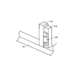
図18と図19に示すとおり、メインフレーム15の後方のリンクベースフレーム42に支持されたスイングアーム45にパラソル立て135を設ける構成としても、強固なパラソル立てとすることができるので、強風や機体の振動で作業中にパラソル136が外れ、作業者が直射日光や雨にさらされることが防止され、作業者の疲労や労力が軽減される。   As shown in FIGS. 18 and 19, even if the parasol stand 135 is provided on the swing arm 45 supported by the link base frame 42 behind the main frame 15, a strong parasol stand can be obtained. Due to this vibration, the parasol 136 is detached during the work, so that the worker is prevented from being exposed to direct sunlight and rain, and the worker's fatigue and labor are reduced.

1 施肥装置付き乗用型田植機 2 走行車体
3 昇降リンク装置 4 苗植付部
5 施肥装置 10 前輪
11 後輪 12 ミッションケース
13 前輪ファイナルケース 15 メインフレーム
18 後輪ギヤケース 20 エンジン
21 第一ベルト伝動装置 23 HST
24(24a、24b) 整地ロータ
24c ロータカバー 25 植付クラッチケース
26 植付伝動軸 27 施肥伝動機構
30 エンジンカバー 31 座席
32 フロントカバー 34 ハンドル
35 フロアステップ 36 リヤステップ(フェンダ)
38 予備苗載台 40 上リンク
41 下リンク 42 リンクベースフレーム
43 縦リンク 44 連結軸
45 スイングアーム 46 昇降油圧シリンダ
47 固定プレート 48 機体側フレーム
48a ピン 49 施肥装置側フレーム
49a パッチン錠 50 伝動ケース
51 苗載台 51a 苗取出口
51b 苗送りベルト 52 苗植付装置
52a 苗植付具
54 傾動位置ロック用プレート
54a 長孔 54b 孔
54c 回動支点 55 センターフロート
56 サイドフロート 57 上下動検出機構
58 繰出量調節ロッド支持プレート
60 肥料ホッパ 60a 蓋
61 繰出部 61a 吐出口
62 施肥ホース 63 施肥ガイド
64 作溝体 66 電動モータ
67 ブロア 68 エアチャンバ
68a ゴム管 68b 樹脂管
71 回動アーム 72 係止具
73A,73B 繰出ロール 74 凹部
75 繰出軸 75a 角軸部
76 ブラシ
77A,77B 繰出停止シャッタ
77a 把手 78 繰出部ケース
78a 固定部分 78b 離脱部分
79 スライド支持部 80 接続管
81 エア切替管 82 カプセル摩耗防止板
82a 回動軸 83 肥料排出口
84 排出シャッタ 84a 回動軸
85 肥料回収管 86 エア切替シャッタ
86a 回動軸 87 肥料回収口
90 肥料回収レバー 90a 回動支点軸
90b ピン 91 シャッタ開閉伝達軸
92 扇形プレート 92a 長穴
93 開閉ギヤ 94 半円形ギヤ
94a ストッパ部 95 エア切替ワイヤ
96 アーム 97 スプリング
98 レバーガイド 98a,98b ガイド穴
100 制御装置 105 繰出駆動軸
108a,108b 繰出伝動ギヤ
111 肥料排出モータ 112 肥料排出スイッチ
113 肥料残量センサ 116 報知手段
117 肥料受けマット 120,121a ギヤ
121 シャッタ開閉板 124 フロート付きのアーム
124a フロート(浮き) 125 トルクスプリング
126 フック 128 ピース
129,130 チューブ
131 太陽光パネル 133 支持枠
135 パラソル立て 157 繰出量調節ロッド
159 電動モータ
DESCRIPTION OF SYMBOLS 1 Riding type rice transplanter with fertilizer 2 Traveling vehicle body 3 Elevating link device 4 Seedling planting part 5 Fertilizer 10 Front wheel 11 Rear wheel 12 Transmission case 13 Front wheel final case 15 Main frame 18 Rear wheel gear case 20 Engine 21 First belt transmission device 23 HST
24 (24a, 24b) Leveling rotor 24c Rotor cover 25 Planting clutch case 26 Planting transmission shaft 27 Fertilizer transmission mechanism 30 Engine cover 31 Seat 32 Front cover 34 Handle 35 Floor step 36 Rear step (fender)
38 Preliminary seedling stage 40 Upper link 41 Lower link 42 Link base frame 43 Vertical link 44 Connecting shaft 45 Swing arm 46 Lifting hydraulic cylinder 47 Fixed plate 48 Airframe side frame 48a Pin 49 Fertilizer application side frame 49a Patchon lock 50 Transmission case 51 Seedling Platform 51a Seedling outlet 51b Seedling feed belt 52 Seedling planting device 52a Seedling planting tool 54 Tilt position locking plate 54a Long hole 54b Hole 54c Rotating fulcrum 55 Center float 56 Side float 57 Vertical movement detection mechanism 58 Feeding amount adjustment Rod support plate 60 Fertilizer hopper 60a Lid 61 Feed part 61a Discharge port 62 Fertilizer hose 63 Fertilizer guide 64 Groove body 66 Electric motor 67 Blower 68 Air chamber 68a Rubber tube 68b Resin tube 71 Rotating arm 72 Locking tools 73A, 73B B 74 Recess 75 Conveying shaft 75a Square shaft 76 Brush
77A, 77B Feeding stop shutter 77a Handle 78 Feeding part case 78a Fixing part 78b Separating part 79 Slide support part 80 Connection pipe 81 Air switching pipe 82 Capsule wear prevention plate 82a Rotating shaft 83 Fertilizer discharge port 84 Discharge shutter 84a Rotating shaft 85 Fertilizer recovery pipe 86 Air switching shutter 86a Rotating shaft 87 Fertilizer recovery port 90 Fertilizer recovery lever 90a Rotating fulcrum shaft 90b Pin 91 Shutter opening / closing transmission shaft 92 Fan-shaped plate 92a Long hole 93 Opening / closing gear 94 Semi-circular gear 94a Stopper section 95 Air switching Wire 96 Arm 97 Spring 98 Lever guide 98a, 98b Guide hole 100 Control device 105 Feeding drive shaft 108a, 108b Feeding transmission gear 111 Fertilizer discharge motor 112 Fertilizer discharge switch 113 Fertilizer remaining amount sensor 116 Notification means 117 Fertilizer receiver DOO 120,121a gear 121 shutter opening and closing plate 124 floats with the arm 124a float (float) 125 Torque spring 126 hooks 128 pieces 129, 130 tube 131 Solar panel 133 supporting frame 135 parasol stand 157 out amount adjusting rod 159 electric motor

Claims (5)

回転数を変更自在なエンジン(20)と、エンジン(20)の回転数の変更を制御する制御装置(100)と、機体の後部に肥料を貯留する施肥貯留部(60)と、施肥貯留部(60)から肥料を受けて所定量ずつ圃場へ放出する繰出装置(61)と、繰出装置(61)から放出される肥料を搬送させる風を発生させる起風装置(67)で構成する圃場に肥料を供給する施肥装置(5)を設けた水田作業車両において、
施肥貯留部(60)から肥料を排出するための肥料排出口(83)を繰出装置(61)から分岐して設け、該肥料排出口(83)には、該肥料排出口(83)の開度を変更する排出開閉板(84)を回動自在に設け、
排出開閉板(84)を回動させて肥料の排出量を変更する排出切替駆動体(111)と、
施肥貯留部(60)から繰出装置(61)と肥料排出口(83)のどちらに肥料が移動するかを切り替える切替操作装置(112)を設け、
切替操作装置(112)を肥料排出側に操作すると、制御装置(100)は繰出装置(61)へ肥料を搬送する場合より排出切替駆動体(111)による排出開閉板(84)の開度を大きくし、且つエンジン回転数を上げて起風装置(67)の風力を強くする制御構成を備えた
ことを特徴とする水田作業車両。
An engine (20) capable of changing the rotational speed, a control device (100) for controlling the change of the rotational speed of the engine (20), a fertilizer storage section (60) for storing fertilizer at the rear of the machine body, and a fertilizer storage section In a field constituted by a feeding device (61) that receives fertilizer from (60) and releases it to the field by a predetermined amount, and a wind-up device (67) that generates wind for conveying the fertilizer released from the feeding device (61). In a paddy field work vehicle provided with a fertilizer supply device (5) for supplying fertilizer,
A fertilizer discharge port (83) for discharging fertilizer from the fertilizer storage part (60) is branched from the feeding device (61), and the fertilizer discharge port (83) is opened with the fertilizer discharge port (83) open. A discharge opening / closing plate (84) for changing the degree of rotation is provided,
A discharge switching drive body (111) for rotating the discharge opening / closing plate (84) to change the discharge amount of the fertilizer;
A switching operation device (112) for switching the fertilizer from the fertilizer storage section (60) to the feeding device (61) or the fertilizer discharge port (83) is provided,
When the switching operation device (112) is operated to the fertilizer discharge side, the control device (100) increases the opening degree of the discharge opening / closing plate (84) by the discharge switching drive body (111) than when the fertilizer is conveyed to the feeding device (61). A paddy field work vehicle comprising a control configuration for increasing the engine speed and increasing the wind force of the wind generator (67).
前記施肥貯留部(60)内に肥料の残量を検出する残量検知部材(113)を設け、
切替操作装置(112)を肥料排出側に操作した際、前記制御装置(100)は、残量検知部材(113)が施肥貯留部(60)内での肥料残量が残量設定量の範囲にあることを検知すると、該残量検知部材(113)が施肥貯留部(60)内の肥料残量が残量設定量の範囲にないことを検知した場合に比べて、制御装置(100)はエンジン回転数を増加させて起風装置(67)の風力を強くすると共に、前記排出開閉板(84)の開度を大きくし、残量検知部材(113)が施肥貯留部(60)内の肥料残量が残量設定量の下限値未満になったことを検知すると、残量検知部材(113)が肥料残量が残量設定量の範囲にあることを検知する場合に比べてエンジン回転数を減少させて起風装置(67)の風力を弱めると共に、前記排出開閉板(84)の開度を小さくする制御構成を備えたことを特徴とする請求項1記載の水田作業車両。
A remaining amount detection member (113) for detecting the remaining amount of fertilizer is provided in the fertilizer storage part (60),
When the switching operation device (112) is operated to the fertilizer discharge side, the control device (100) indicates that the remaining amount of fertilizer in the fertilizer storage section (60) is within the range of the remaining amount set amount. When the remaining amount detecting member (113) detects that the remaining amount of fertilizer in the fertilizer storage part (60) is not within the range of the remaining amount setting amount, the control device (100) is detected. Increases the engine speed and strengthens the wind power of the wind-up device (67), increases the opening of the discharge opening / closing plate (84), and the remaining amount detection member (113) is placed in the fertilizer storage section (60). When it is detected that the remaining amount of fertilizer is less than the lower limit of the remaining amount setting amount, the remaining amount detecting member (113) is compared with the case where the remaining amount of fertilizer is detected within the range of the remaining amount setting amount. The rotational speed is decreased to weaken the wind force of the wind generator (67) and the exhaust opening is reduced. Paddy working vehicle according to claim 1, further comprising a control arrangement for reducing the degree of opening of the plate (84).
残量検知部材(113)が、施肥貯留部(60)内の肥料残量が設定量の上限値を超えたことを検知すると、残量検知部材(113)が施肥貯留部(60)内の肥料残量が設定量の範囲にあることを検知する場合に比べて、制御装置(100)はエンジン回転数を減少させて起風装置(67)の風力を弱めると共に排出開閉板(84)の開度を小さくする制御構成を備えた
ことを特徴とする請求項2記載の水田作業車両。
When the remaining amount detection member (113) detects that the remaining amount of fertilizer in the fertilizer storage unit (60) exceeds the upper limit value of the set amount, the remaining amount detection member (113) in the fertilizer storage unit (60) Compared to the case where it is detected that the remaining amount of fertilizer is within the set amount range, the control device (100) reduces the engine speed to weaken the wind force of the wind-up device (67) and the discharge opening / closing plate (84). The paddy field work vehicle according to claim 2, further comprising a control structure for reducing the opening degree.
前記残量検知部材(113)が、施肥貯留部(60)内の肥料残量が設定量の範囲内にあることを検知すると作動するタイマー(114)と、該タイマー(114)で設定した排出時間が経過すると作動する報知手段(116)を設け、
該報知手段(116)作動後の一定時間内に切替操作装置(112)を操作すると、制御装置(100)は前記排出開閉板(84)の開度を維持すると共に、
報知手段(116)作動後の一定時間内に切替装置(112)が操作されないと、制御装置(100)は排出開閉板(84)を閉じて肥料が出ない状態に切り替える制御構成としたことを特徴とする請求項2又は3に記載の水田作業車両。
A timer (114) that operates when the remaining amount detecting member (113) detects that the remaining amount of fertilizer in the fertilizer storage section (60) is within a set amount range, and a discharge set by the timer (114) Providing a notification means (116) which is activated when time passes;
When the switching operation device (112) is operated within a predetermined time after the operation of the notification means (116), the control device (100) maintains the opening degree of the discharge opening / closing plate (84), and
When the switching device (112) is not operated within a certain time after the operation of the notification means (116), the control device (100) is configured to switch to a state in which the fertilizer is not released by closing the discharge opening / closing plate (84). The paddy field work vehicle according to claim 2 or 3, characterized by the above-mentioned.
前記施肥貯留部(60)に肥料を受ける肥料受け部材(117)を配置し、該肥料受け部材(117)の一端部を繰出装置(61)に接触させて配置したことを特徴とする請求項1記載の水田作業車両。   The fertilizer receiving member (117) for receiving fertilizer is disposed in the fertilizer storage section (60), and one end of the fertilizer receiving member (117) is disposed in contact with the feeding device (61). The paddy field work vehicle according to 1.
JP2011016076A 2011-01-28 2011-01-28 Paddy field working vehicle Withdrawn JP2012152180A (en)

Priority Applications (1)

Application Number Priority Date Filing Date Title
JP2011016076A JP2012152180A (en) 2011-01-28 2011-01-28 Paddy field working vehicle

Applications Claiming Priority (1)

Application Number Priority Date Filing Date Title
JP2011016076A JP2012152180A (en) 2011-01-28 2011-01-28 Paddy field working vehicle

Publications (1)

Publication Number Publication Date
JP2012152180A true JP2012152180A (en) 2012-08-16

Family

ID=46834624

Family Applications (1)

Application Number Title Priority Date Filing Date
JP2011016076A Withdrawn JP2012152180A (en) 2011-01-28 2011-01-28 Paddy field working vehicle

Country Status (1)

Country Link
JP (1) JP2012152180A (en)

Cited By (3)

* Cited by examiner, † Cited by third party
Publication number Priority date Publication date Assignee Title
JP2017006075A (en) * 2015-06-24 2017-01-12 井関農機株式会社 Seedling transplanter
CN112658025A (en) * 2020-12-25 2021-04-16 芜湖斯质设计有限公司 Efficient centrifugal spraying type restoration liquid spraying device for ecological protection
CN116420485A (en) * 2023-06-12 2023-07-14 大同市现代农业发展中心 Intelligent variable fertilizing device based on Internet of things

Cited By (5)

* Cited by examiner, † Cited by third party
Publication number Priority date Publication date Assignee Title
JP2017006075A (en) * 2015-06-24 2017-01-12 井関農機株式会社 Seedling transplanter
CN112658025A (en) * 2020-12-25 2021-04-16 芜湖斯质设计有限公司 Efficient centrifugal spraying type restoration liquid spraying device for ecological protection
CN112658025B (en) * 2020-12-25 2022-07-12 东至绿丰景观园林绿化有限公司 Efficient centrifugal spraying type restoration liquid spraying device for ecological protection
CN116420485A (en) * 2023-06-12 2023-07-14 大同市现代农业发展中心 Intelligent variable fertilizing device based on Internet of things
CN116420485B (en) * 2023-06-12 2023-08-25 大同市现代农业发展中心 Intelligent variable fertilizing device based on Internet of things

Similar Documents

Publication Publication Date Title
JP2012152180A (en) Paddy field working vehicle
JP2010136629A (en) Direct seeding machine
JP2014121280A (en) Seedling transplanter
JP2011101615A (en) Fertilizing device
JP5209553B2 (en) Supply control mechanism for work equipment
JP5716308B2 (en) Granule dispenser
JP2013066449A (en) Seedling transplanter
JP2007174930A (en) Seedling transplanter with ground working apparatus
JP6458496B2 (en) Fertilizer
TWI625093B (en) A fertilizing apparauts
JP4082156B2 (en) Powder and particle dispenser
JP6617795B2 (en) Fertilizer
JP5464254B2 (en) Direct seeding machine
JP5387654B2 (en) Seedling transplanter with ground working device
JP2016010321A (en) Seedling transplanter
JP2010000014A (en) Seedling transplanter
JP3968488B2 (en) Seedling transplanter
JP3726838B2 (en) Fertilizer applicator
JP2019106896A (en) Seedling transplanter
JP2006034175A (en) Seedling transplanter
JP3661457B2 (en) Agricultural work machine with fertilizer
JP5056746B2 (en) Multi-purpose agricultural machine
JP2006081464A (en) Apparatus for delivering granule
JP2006115779A (en) Storage tank
JP2006129838A (en) Granular powder-sending out device

Legal Events

Date Code Title Description
A300 Withdrawal of application because of no request for examination

Free format text: JAPANESE INTERMEDIATE CODE: A300

Effective date: 20140401