JP2012152134A - Variable-diameter roll baler - Google Patents

Variable-diameter roll baler Download PDF

Info

Publication number
JP2012152134A
JP2012152134A JP2011013868A JP2011013868A JP2012152134A JP 2012152134 A JP2012152134 A JP 2012152134A JP 2011013868 A JP2011013868 A JP 2011013868A JP 2011013868 A JP2011013868 A JP 2011013868A JP 2012152134 A JP2012152134 A JP 2012152134A
Authority
JP
Japan
Prior art keywords
roll
variable
molding
roll bale
roller
Prior art date
Legal status (The legal status is an assumption and is not a legal conclusion. Google has not performed a legal analysis and makes no representation as to the accuracy of the status listed.)
Granted
Application number
JP2011013868A
Other languages
Japanese (ja)
Other versions
JP5799456B2 (en
Inventor
Yasuhiro Tachibana
保宏 橘
Tetsuo Kawade
哲生 川出
Hirokatsu Shito
博克 志藤
Shinya Harada
伸也 原田
Hiroshi Yokouchi
博史 横内
Current Assignee (The listed assignees may be inaccurate. Google has not performed a legal analysis and makes no representation or warranty as to the accuracy of the list.)
National Agriculture and Food Research Organization
IHI Star Machinery Corp
Original Assignee
National Agriculture and Food Research Organization
IHI Star Machinery Corp
Priority date (The priority date is an assumption and is not a legal conclusion. Google has not performed a legal analysis and makes no representation as to the accuracy of the date listed.)
Filing date
Publication date
Application filed by National Agriculture and Food Research Organization, IHI Star Machinery Corp filed Critical National Agriculture and Food Research Organization
Priority to JP2011013868A priority Critical patent/JP5799456B2/en
Publication of JP2012152134A publication Critical patent/JP2012152134A/en
Application granted granted Critical
Publication of JP5799456B2 publication Critical patent/JP5799456B2/en
Expired - Fee Related legal-status Critical Current
Anticipated expiration legal-status Critical

Links

Images

Landscapes

  • Storage Of Harvested Produce (AREA)

Abstract

PROBLEM TO BE SOLVED: To efficiently form a well-formed tight roll bale.SOLUTION: A roll baler is provided, including: a conveyor 3 for charging a roll bale-forming chamber 4 with a to-be-formed material; and the roll bale-forming chamber 4 functioning to make a compressive forming such a to-be-formed material as to have been charged by the conveyor 3 into roll bales R1 and R2 using one or more belts 6, 7 and 8. In this roll baler, the roll bale-forming chamber 4 has: a charging port 40 for such a to-be-formed material; and a variable roller wound with the belts 6, 7 and 8 and axially supported variably in its position off the center of the roll bale-forming chamber 4 so as to expand the chamber 4 according to the respective diameters of the to-be-formed roll bales R1 and R2; wherein the charging port is provided so that its opening direction represents such a direction as not to face each other on the variable direction of the variable roller.

Description

本発明は、径の異なるロールベールの成形が可能な可変径ロールベーラに関する。   The present invention relates to a variable diameter roll baler capable of forming roll bales having different diameters.

径の異なるロールベールの成形が可能なロールベーラは、成形室に投入された被成形材料が円柱状のロールベールに成形される際に、このロールベールの径の拡大に伴って、成形室の径を拡大するようにしたものが知られている。   A roll baler capable of forming roll balers with different diameters is produced when the material to be molded put into the molding chamber is formed into a cylindrical roll bale. It is known to expand.

下記特許文献1に記載の成形室は、投入口が被成形材料のピックアップ部と連続するように下向きに開口され、ピックアップ部から投入口を経て成形室に投入された被成形材料が、相互に対面して反対方向に動くベルトによって、円柱状のロールベールに成形するようになっている。そして、このロールベールの径の拡大に伴う圧力がベルトに作用し、この圧力でベルトを巻掛けたローラを、投入口の開口方向と対向する上方に変位させることによって、成形室を拡大するようになっている。   The molding chamber described in the following Patent Document 1 is opened downward so that the inlet is continuous with the pickup portion of the molding material, and the molding materials introduced into the molding chamber through the inlet from the pickup portion are mutually connected. It is formed into a cylindrical roll bale by a belt that faces and moves in the opposite direction. And the pressure accompanying the enlargement of the diameter of the roll bale acts on the belt, and the roller around which the belt is wound by this pressure is displaced upward to oppose the opening direction of the inlet, so that the molding chamber is enlarged. It has become.

特許文献2に記載の成形室は、投入口が成形室の中心よりもやや下側、且つ斜め下向きに開口され、この投入口に向けて配したコンベアから成形室に投入される被成形材料が、タイトバーの回転によって、円柱状のロールベールに成形されるようになっている。そして、このロールベールの径の拡大に伴う圧力がタイトバーに作用し、この圧力でタイトバーを径方向外側に変位させることによって、成形室をロールベールの径及び形状に伴って拡大するようになっている。   In the molding chamber described in Patent Document 2, the input port is opened slightly below the center of the molding chamber and obliquely downward, and a molding material to be input into the molding chamber from a conveyor disposed toward the input port is provided. A cylindrical roll bale is formed by the rotation of the tight bar. And the pressure accompanying the expansion of the diameter of the roll bale acts on the tight bar, and by displacing the tight bar radially outward with this pressure, the molding chamber is expanded with the diameter and shape of the roll bale. Yes.

これら特許文献1及び特許文献2の成形室は、この成形室の径が拡大すると同時に、径を縮小させる方向(ロールベールを圧縮する方向)に力が作用するようになっており、この径を縮小させる方向の力によって、ロールベールを圧縮しながら成形するようになっている。   In the molding chambers of these patent documents 1 and 2, the force acts in the direction of reducing the diameter (the direction in which the roll bale is compressed) at the same time that the diameter of the molding chamber is increased. The roll bale is molded while being compressed by the force in the reducing direction.

特開昭60−188013号公報Japanese Patent Laid-Open No. 60-188013 特開2007−267675号公報JP 2007-267675 A

特許文献1及び特許文献2の従来技術によると、成形室がロールベールの径及び形状に伴って拡大し、この拡大と同時に成形室を縮小する方向に力が生じるようにしているので、小径のロールベールから大径のロールベールまで、固く締まったロールベールを無段階で成形することができる。   According to the prior arts of Patent Document 1 and Patent Document 2, the molding chamber expands with the diameter and shape of the roll bale, and force is generated in the direction of contracting the molding chamber simultaneously with this expansion. From a roll bale to a large diameter roll bale, a tight roll bale can be formed in a stepless manner.

しかしながら、前述の被成形材料には、細断されたものがあるが、このような被成形材料は、まとまり難くロールベール成形時において崩れ易いということがある。特に、特許文献1の従来技術では、ロールベールの上方への変位によって生じる下方への圧縮力が、成形室の全体の内、最も強くなるため、投入口の開口部に向かう方向に作用する圧縮力によって、被成形材料が投入口に向けて崩れながらこの投入口から漏れ出してしまうという問題があった。   However, some of the above-mentioned molding materials are chopped, but such molding materials are difficult to be organized and may easily collapse during roll bale molding. In particular, in the prior art of Patent Document 1, the downward compressive force generated by the upward displacement of the roll bale is the strongest in the entire molding chamber, so that the compression acts in the direction toward the opening of the inlet. There is a problem in that the material to be molded leaks out from the inlet while being collapsed toward the inlet due to the force.

特許文献2の従来技術では、成形されるロールベールに対して、投入口を除くロールベールの周囲面から径方向に圧縮力を平均的に作用させる構成であるが、このような成形室においても、斜め下向きの投入口に向かう圧縮力によって、被成形材料の種類によっては、成形室が満量近くになったとき、被成形材料が成形室に入らなくなる現象が生じてしまうという問題があった。   In the prior art of Patent Document 2, it is a configuration in which a compressive force acts on the roll bale to be formed in the radial direction from the peripheral surface of the roll bale excluding the inlet, but also in such a molding chamber. Depending on the type of molding material, there is a problem that the molding material does not enter the molding chamber when the molding chamber is almost full due to the compressive force directed diagonally downward. .

そのため、特許文献1及び特許文献2のような成形室を備えるロールベーラの場合、ロールベールの成形において、前述のように被成形材料が成形室に入らなくなることによって、被成形材料の成形室外への漏れ出しが生じ、この漏れ出しによって被成形材料が無駄になる、或いは、形状の良い締まったロールベールの成形、効率よいロールベールの成形ができないという問題があった。   Therefore, in the case of a roll baler having a molding chamber such as Patent Document 1 and Patent Document 2, in the molding of the roll bale, the molding material does not enter the molding chamber as described above, so that the molding material is moved out of the molding chamber. There was a problem that leakage occurred, and the material to be molded was wasted due to this leakage, or that a roll veil having a good shape and tightening could not be formed efficiently.

本発明は、このような問題に対処することを課題とするものである。すなわち、ロールベール成形中における被成形材料の投入口からの漏れ出しを防止できるようにすること、投入口からの被成形材料の漏れ出しを防止することで、被成形材料を無駄なく有効に使用できるとともに、成形室が満量近くになったときにも、被成形材料を成形室に円滑に入れることができ、且つ形状の良い締まったロールベールの成形、効率よいロールベールの成形ができること等、が本発明の目的である。   An object of the present invention is to deal with such a problem. In other words, the molding material can be effectively used without waste by preventing the molding material from leaking from the inlet during roll bale molding and preventing the molding material from leaking from the inlet. In addition, the molding material can be smoothly put into the molding chamber even when the molding chamber is almost full, and a well-shaped and tight roll bale can be formed, and an efficient roll bale can be formed. Is the object of the present invention.

このような目的を達成するために、本発明による可変径ロールベーラは、以下の構成を少なくとも具備するものである。   In order to achieve such an object, the variable diameter roll baler according to the present invention has at least the following configuration.

ロールベール成形室に被成形材料を投入する投入コンベアと、該投入コンベアにより投入された被成形材料を、一つ又は複数のベルトを用いてロールベールに圧縮成形するロールベール成形室と、を備え、前記ロールベール成形室は、前記被成形材料の投入口と、前記ベルトが巻回され、成形される前記ロールベールの径に応じて、前記ロールベール成形室を拡開するように、該ロールベール成形室の中心からの位置を可変に軸支された可変ローラと、を備え、前記投入口を、該投入口の開口方向が前記可変ローラの可変方向と正対しない方向となるように設けたことを特徴とする。   A feed conveyor for charging the material to be molded into the roll bale molding chamber, and a roll bale molding chamber for compressing and molding the material to be molded charged by the charging conveyor into a roll bale using one or a plurality of belts. The roll bale molding chamber is configured to expand the roll bale molding chamber according to the diameter of the roll bale to be formed by charging the inlet of the molding material and the belt. A variable roller rotatably supported at a position from the center of the bale molding chamber, and the input port is provided so that the opening direction of the input port does not face the variable direction of the variable roller It is characterized by that.

このような特徴を有することで本発明は以下の効果を奏する。すなわち、成形される前記ロールベールの径に応じて、前記ロールベール成形室を拡開するように、該ロールベール成形室の中心からの位置を可変に軸支された可変ローラと、を備え、前記投入口を、該投入口の開口方向が前記可変ローラの可変方向と正対しない方向となるように設けたので、ロールベール成形中における被成形材料の投入口からの漏れ出しを防止できる。投入口からの被成形材料の漏れ出しを防止することで、被成形材料を無駄なく有効に使用できるとともに、成形室が満量近くになったときにも、被成形材料を成形室に円滑に入れることができ、且つ形状の良い締まったロールベールの成形、効率よいロールベールの成形ができる。   By having such characteristics, the present invention has the following effects. In other words, according to the diameter of the roll bale to be molded, a variable roller that is pivotally supported by a variable position from the center of the roll bale molding chamber so as to expand the roll bale molding chamber, Since the input port is provided so that the opening direction of the input port does not face the variable direction of the variable roller, leakage of the molding material from the input port during roll bale molding can be prevented. By preventing the molding material from leaking from the inlet, the molding material can be used effectively without waste, and when the molding chamber is nearly full, the molding material can be smoothly transferred to the molding chamber. It is possible to form a roll veil that can be inserted and has a good shape, and to efficiently form a roll bale.

本発明に係る可変径ロールベーラの第1実施形態を示す概略構成図。The schematic block diagram which shows 1st Embodiment of the variable diameter roll baler which concerns on this invention. 図1におけるロールベール成形室の拡大図で最小のロールベール成形状態を示す。FIG. 1 is an enlarged view of the roll bale molding chamber in FIG. 1 and shows the minimum roll bale molding state. 図1におけるロールベール成形室の拡大図で最大のロールベール成形状態を示す。The largest roll bale molding state is shown in the enlarged view of the roll bale molding chamber in FIG. 本発明に係る可変径ロールベーラの第2実施形態を示す概略構成図。The schematic block diagram which shows 2nd Embodiment of the variable diameter roll baler which concerns on this invention. 本発明に係る可変径ロールベーラの第3実施形態を示すロールベール成形室の拡大概略構成図。The expansion schematic block diagram of the roll bale molding room which shows 3rd Embodiment of the variable diameter roll baler which concerns on this invention. 図5におけるロールベール成形室において最小のロールベール成形状態を示す。The minimum roll bale molding state is shown in the roll bale molding chamber in FIG.

本発明の可変径ロールベーラがロールベールを成形することが可能な被成形材料は、青刈りトウモロコシや牧草等の飼料作物、食品加工後の食品残渣、粗飼料や濃厚飼料等を混合調整した混合飼料等の家畜用飼料に用いる各種材料、籾殻、麦殻、木屑、おがくず、敷料、家畜糞等の肥料に用いる各種材料等である。本発明の可変径ロールベーラは、特に、前述の各種材料を細断してなる被成形材料をロールベールに成形するのに効果的な細断型のものである。   The molding material that the variable diameter roll baler of the present invention can form a roll bale includes feed crops such as green corn and pasture, mixed food such as food residues after food processing, rough feed and concentrated feed, etc. Various materials used for livestock feed, various materials used for fertilizers such as rice husks, wheat husks, wood chips, sawdust, litter, and livestock manure. The variable diameter roll baler of the present invention is of a chopping type that is particularly effective for forming a material to be formed by chopping the above-mentioned various materials into a roll bale.

前述の可変径ロールベーラは、トラクター等の走行車に牽引される牽引式、自走式、据置式を含む。また、この可変径ロールベーラは、成形したロールベールにネット、トワイン(ロープ)、シート等の結束資材や梱包資材を巻回して圃場に排出するもの、この結束資材や梱包資材が巻回されたロールベールをラップするラッピングマシンを備えた複合型のものを含む。   The aforementioned variable-diameter roll baler includes a towed type, a self-propelled type, and a stationary type that are pulled by a traveling vehicle such as a tractor. In addition, this variable diameter roll baler is a roll in which binding materials and packing materials such as nets, twains (ropes) and sheets are wound around the formed roll bale and discharged to the field, and rolls in which the binding materials and packing materials are wound Including composite type with wrapping machine for wrapping bale.

投入口は、成形されるロールベールの最大径の中心位置より下部にあっても、前述の構成により被成形材料の湧き出し現象を防止できるが、より好ましくは、成形される前記ロールベールの最大径の中心位置よりも上部である。   Even if the charging port is below the center position of the maximum diameter of the roll bale to be molded, the above-described configuration can prevent the phenomenon of the material to be molded, but more preferably, the maximum size of the roll bale to be molded is maximum. It is above the center position of the diameter.

被成形材料をロールベール成形室内により確実に投入して、この被成形材料を無駄なく有効に使用するという点において、投入コンベアの上流側端部を、投入口の下端部と重畳するように配置することが好ましい。   Arranged so that the upstream end of the input conveyor overlaps with the lower end of the input port in that the material to be molded is reliably charged into the roll bale molding chamber and used efficiently without waste. It is preferable to do.

本発明の可変径ロールベーラは、可変ローラが、ロールベールの周方向に向かい合って軸支された第1可動ローラ及び第2可動ローラと、該第1可動ローラ及び第2可動ローラよりも可変方向外側に軸支された第3可動ローラと、を備え、ベルトを、第1可動ローラ及び第2可動ローラに対して、ロールベール成形室とは反対側の面を接触させて巻回するとともに、第3可動ローラに対して、ロールベール成形室側の面を接触させて巻回することで、ロールベール成形室と連通する凹部が構成され、この凹部内に、該凹部内への前記被成形材料の侵入を抑制するスクレーパを備えることが好ましい。   The variable-diameter roll baler of the present invention includes a first movable roller and a second movable roller in which the variable roller is pivotally supported facing the circumferential direction of the roll bale, and the outer side in the variable direction than the first movable roller and the second movable roller. A belt that is wound around the first movable roller and the second movable roller with the surface opposite to the roll bale molding chamber in contact with the third movable roller. A concave portion communicating with the roll bale molding chamber is formed by contacting the surface of the roll veil molding chamber with the three movable rollers, and the material to be molded into the concave portion is formed in the concave portion. It is preferable to provide a scraper that suppresses intrusion.

更に、本発明の可変径ロールベーラは、複数のベルトを有するロールベール成形室を備えた可変径ロールベーラであって、ロールベール成形室の下部に配置されるベルトが、ロールベール成形室を構成する他のローラより投入コンベア側に突出して設けられていることが好ましい。   Furthermore, the variable diameter roll baler of the present invention is a variable diameter roll baler provided with a roll bale forming chamber having a plurality of belts, and the belt disposed at the lower part of the roll bale forming chamber constitutes the roll bale forming chamber. It is preferable that the roller is provided so as to protrude from the roller to the input conveyor side.

以下、可変径ロールベーラ(以下、ロールベーラという)1の第1実施形態を図面に基づいて説明する。本実施形態において例示するロールベーラ1は、青刈りトウモロコシや牧草等の飼料作物を細断した被成形材料(図示せず)をロールベールに成形するのに適した細断型のロールベーラ1である。   Hereinafter, a first embodiment of a variable diameter roll baler (hereinafter referred to as a roll baler) 1 will be described with reference to the drawings. The roll baler 1 exemplified in the present embodiment is a chopped roll baler 1 suitable for forming a molding material (not shown) obtained by chopping feed crops such as green corn and pasture into a roll bale.

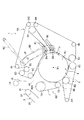
ロールベーラ1の基本構成は、上流側からホッパ2、投入コンベア3、ロールベール成形室(以下、成形室という)4を備えており、ホッパ2に貯留された被成形材料を、投入コンベア3を介して成形室4に投入し、この成形室4の成形駆動によってロールベールR1、R2(図2、図3参照)を成形するようになっている。ロールベールR1、R2が所定径に成形されると、投入コンベア3の駆動を停止するとともに、ネット10をネット供給部1Aから成形室4に供給し、この成形室4の成形駆動によってロールベールR1、R2に巻付け、このネット10の巻付け終了後に、成形室4の下流側半部4Aを開いて(図示せず)ロールベールR1、R2を機外に排出するようになっている。ネット10は、成形室4に確保された投入口40から供給されるようになっている。   The basic configuration of the roll baler 1 includes a hopper 2, a charging conveyor 3, and a roll bale molding chamber (hereinafter referred to as a molding chamber) 4 from the upstream side, and the molding material stored in the hopper 2 is passed through the charging conveyor 3. The roll bales R1 and R2 (see FIGS. 2 and 3) are molded by the molding chamber 4 being driven by the molding drive. When the roll bales R1 and R2 are formed to have a predetermined diameter, the input conveyor 3 is stopped and the net 10 is supplied from the net supply unit 1A to the forming chamber 4, and the roll bale R1 is driven by the forming drive of the forming chamber 4. After the winding of the net 10 is finished, the downstream half 4A of the molding chamber 4 is opened (not shown) and the roll bales R1 and R2 are discharged out of the machine. The net 10 is supplied from an input port 40 secured in the molding chamber 4.

尚、本実施形態では、ホッパ2側(図1において左側)を上流側とし、成形室4側(図1において右側)を下流側として説明する。また、本実施形態では、ロールベールR1、R2に対してネット10を巻付ける形態を例示したが、本発明のロールベーラは、ネット10に換えてロールベールR1、R2に対してトワインを巻付ける形態も含まれ、この場合、ネット供給部1Aに換えてトワイン供給部が設置される(図示せず)。   In the present embodiment, the hopper 2 side (left side in FIG. 1) is the upstream side, and the molding chamber 4 side (right side in FIG. 1) is the downstream side. Moreover, although the form which winds the net | network 10 around roll bale R1, R2 was illustrated in this embodiment, the roll baler of this invention replaces with the net | network 10 and forms the twain wound around roll bale R1, R2. In this case, a twain supply unit is installed in place of the net supply unit 1A (not shown).

ホッパ2は、成形室4と間にホッパ2の一部を構成するように設置された投入コンベア3により区切られた、ロールベーラ1の最上流側(図1において左側)の空間であり、図1において逆三角形状を呈する空間である。このようなホッパ2に貯留される被成形材料は、投入コンベア3により運搬され、投入口40から成形室4内に投入される。   The hopper 2 is a space on the uppermost stream side (left side in FIG. 1) of the roll baler 1, which is partitioned by a charging conveyor 3 installed so as to constitute a part of the hopper 2 between the molding chamber 4 and FIG. Is a space having an inverted triangular shape. The molding material stored in the hopper 2 is transported by the input conveyor 3 and is input into the molding chamber 4 from the input port 40.

投入コンベア3は、ホッパ2の最下部20よりも下側の位置から投入口40にわたって傾斜状に設置されている。投入コンベア3のコンベアベルト30の表面には、被成形材料を支持する複数の支持突起31が突設されており、この支持突起31が運搬される被成形材料を支持することによって、この被成形材料を投入コンベア3の傾斜に沿って滑り落ちるのを防止できるようになっている。また、投入コンベア3の下流側端部32を、投入口40の下端部40Aと上下方向で重畳するように配置して、被成形材料の投入口40への投入時に、この被成形材料のこぼれ落ちを抑制している。また、投入コンベア3の上流側端部33をホッパ2の最下部20の直下に配置している。   The input conveyor 3 is installed in an inclined shape from a position below the lowermost part 20 of the hopper 2 to the input port 40. A plurality of support protrusions 31 are provided on the surface of the conveyor belt 30 of the input conveyor 3 so as to support the material to be molded. The support protrusions 31 support the material to be transported to support the material to be molded. It is possible to prevent the material from sliding down along the inclination of the input conveyor 3. Further, the downstream end portion 32 of the input conveyor 3 is arranged so as to overlap the lower end portion 40A of the input port 40 in the vertical direction, and when the material to be molded is input to the input port 40, the material to be molded is spilled down. Is suppressed. Further, the upstream end portion 33 of the charging conveyor 3 is disposed directly below the lowermost portion 20 of the hopper 2.

成形室4は、投入される被成形材料を複数のベルト6、7、8を用いてロールベールR1、R2に圧縮成形するとともに、成形されるロールベールR1、R2の径に応じて、ベルト6の成形室4の中心Cからの位置を可変に設けた構成のものであり、ベルト6とベルト7との間に投入口40が確保されている。   The molding chamber 4 compresses and molds the material to be molded into roll bales R1 and R2 using a plurality of belts 6, 7, and 8, and the belt 6 according to the diameter of the roll bales R1 and R2 to be molded. The position from the center C of the molding chamber 4 is variably provided, and an insertion port 40 is secured between the belt 6 and the belt 7.

この成形室4は、ベルト6、7、8をロールベールの周方向に沿うように配置することにより構成されている。尚、成形室4は、実際には、ホッパ2から成形室4にわたって設けられた側板(図示せず)を含んで成形室4が構成されている。また、ホッパ2についても同様であり、前述の側板を含んで構成されている。   The molding chamber 4 is configured by arranging belts 6, 7, and 8 along the circumferential direction of the roll bale. Note that the molding chamber 4 actually includes a side plate (not shown) provided from the hopper 2 to the molding chamber 4. The same applies to the hopper 2 and includes the aforementioned side plate.

ベルト6は、投入口40を境として成形室4の下流側半部4Aを構成するものであり、可変ローラの一例である第1可動ローラ6A及び第2可動ローラ6Bと、8個の固定ローラ6C〜6E及び固定ローラ6G〜6Kと1個の可動テンションローラ6Fとにわたりエンドレス状に巻回して張設されている。可動ローラ6A、第2可動ローラ6B及び固定ローラ6C〜6Kは、その軸線をロールベールR1、R2の軸線と平行として回転可能に軸支されている。   The belt 6 constitutes the downstream half 4A of the molding chamber 4 with the insertion port 40 as a boundary. The first movable roller 6A and the second movable roller 6B, which are examples of variable rollers, and eight fixed rollers. 6C to 6E and fixed rollers 6G to 6K and one movable tension roller 6F are wound and stretched endlessly. The movable roller 6A, the second movable roller 6B, and the fixed rollers 6C to 6K are rotatably supported with their axis lines parallel to the axis lines of the roll bales R1 and R2.

第1可動ローラ6A、第2可動ローラ6Bは、一端側が、軸線をロールベールR1、R2の軸線と平行とする回転軸Pに軸支された可動アーム60に軸支され、他端側が、前述の側板に開孔された長孔61、61に軸支されている。この第1可動ローラ6A、第2可動ローラ6Bは、成形中のロールベールR1、R2のベルト6に対する押圧力が、このベルト6を介して作用するようになっており、この押圧力により、長孔61、61に沿って、成形室4の中心Cから下流側へ移動するようになっている。この第1可動ローラ6A、第2可動ローラ6Bの下流側への移動によって、ベルト6の成形室4の中心Cからの位置を可変にすることができる。   One end of each of the first movable roller 6A and the second movable roller 6B is pivotally supported by a movable arm 60 that is pivotally supported by a rotation axis P whose axis is parallel to the axis of the roll bail R1 or R2, and the other end is previously described. Are supported by long holes 61, 61 opened in the side plate. The first movable roller 6A and the second movable roller 6B are configured such that the pressing force against the belt 6 of the roll bales R1 and R2 being formed acts via the belt 6, and the pressing force causes a long time. It moves from the center C of the molding chamber 4 to the downstream side along the holes 61 and 61. By moving the first movable roller 6A and the second movable roller 6B to the downstream side, the position of the belt 6 from the center C of the molding chamber 4 can be made variable.

この長孔61、61は、長手方向が可動アーム60の回転軸Pと同心とする円弧となるように形成されている。可動アーム60は、第1可動ローラ6A、第2可動ローラ6Bの移動に伴って、回転軸Pを回転中心として回転するようになっている。   The long holes 61 and 61 are formed so that the longitudinal direction is an arc concentric with the rotation axis P of the movable arm 60. The movable arm 60 is configured to rotate about the rotation axis P with the movement of the first movable roller 6A and the second movable roller 6B.

可動アーム60の回転軸Pを境とする上側の端部には、油圧シリンダ62が連結されている。油圧シリンダ62は、収縮する方向に圧力が作用しており、第1可動ローラ6A、第2可動ローラ6Bの移動に伴う可動アーム60の回転に伴って、前述の圧力に抗して伸長するようになっている。この油圧シリンダ62は、可動アーム60の回転位置にかかわらず、一定の圧力となるように制御されている。また、可動アーム60の回転軸Pには、角度計が設置されており、設定した角度に達すると、投入コンベア3の運搬駆動が停止するとともに、ネット10の供給が開始されるように制御されている。   A hydraulic cylinder 62 is connected to the upper end of the movable arm 60 with the rotation axis P as a boundary. The hydraulic cylinder 62 is applied with pressure in the direction of contraction, and expands against the aforementioned pressure as the movable arm 60 rotates as the first movable roller 6A and the second movable roller 6B move. It has become. The hydraulic cylinder 62 is controlled to have a constant pressure regardless of the rotational position of the movable arm 60. Further, an angle meter is installed on the rotation axis P of the movable arm 60, and when the set angle is reached, the conveyance drive of the input conveyor 3 is stopped and the supply of the net 10 is started. ing.

すなわち、ロールベールが目的の径に至ったときに投入コンベア3の運搬駆動が停止するように制御されているので、目的の径のロールベールを確実に成形することができる。また、ベルト6の位置が成形室4の中心から外側へ変化する際に、油圧シリンダ62の収縮方向への圧力が可動アーム60を介してベルト6に作用し、このベルト6に作用する収縮方向への圧力をロールベールに作用させることによって、形状良く締まった状態のロールベールを成形することができる。   That is, since the conveyance drive of the input conveyor 3 is controlled to stop when the roll bale reaches the target diameter, the roll bale with the target diameter can be reliably formed. Further, when the position of the belt 6 changes from the center of the molding chamber 4 to the outside, the pressure in the contraction direction of the hydraulic cylinder 62 acts on the belt 6 via the movable arm 60, and the contraction direction that acts on the belt 6. By applying a pressure to the roll bale, a roll bale with a good shape can be formed.

また、長孔61、61は、その長手方向が投入口40の開口方向とほぼ直角に交差するように開孔されており、この長孔61、61に沿って移動する第1可動ローラ6A、第2可動ローラ6Bの移動方向を投入口40の開口方向と正対させないようになっている。すなわち、可動アーム60を介して油圧シリンダ62の圧力が第1可動ローラ6A、第2可動ローラ6Bに作用したとき、成形室4で成形されるロールベールR1、R2に対する第1可動ローラ6A、第2可動ローラ6Bの成形室4の中心C方向への圧力が、投入口40の開口方向と交差する方向に作用し、ロールベールR1、R2を投入口40の開口方向と正対しない方向から圧縮するため、ロールベールR1、R2の最も崩れ易い投入口40付近の崩れを抑制することができ、しかも、被成形材料が成形室4に入らなくなる現象を防止することができる。   Further, the long holes 61 and 61 are opened such that the longitudinal direction thereof intersects the opening direction of the charging port 40 substantially at right angles, and the first movable roller 6A that moves along the long holes 61 and 61, The moving direction of the second movable roller 6B is not made to face the opening direction of the insertion port 40. That is, when the pressure of the hydraulic cylinder 62 acts on the first movable roller 6A and the second movable roller 6B via the movable arm 60, the first movable roller 6A and the first movable roller 6A for the roll bales R1 and R2 formed in the molding chamber 4 2 The pressure of the movable roller 6B in the direction of the center C of the molding chamber 4 acts in a direction intersecting the opening direction of the charging port 40, and compresses the roll bales R1 and R2 from the direction not facing the opening direction of the charging port 40. Therefore, it is possible to suppress the collapse of the roll bales R1 and R2 in the vicinity of the inlet 40 that is most likely to collapse, and to prevent a phenomenon that the molding material does not enter the molding chamber 4.

尚、成形されたロールベールR1、R2に対してネット10が所定量で巻付けられたとき、駆動源の駆動を停止させるように制御してもよいし、駆動源の駆動停止がされたときに、この駆動停止をランプ等の点灯又は点滅によって知らせたり、ブザー等の音声によって知らせたりするように制御してもよい(図示せず)。また、駆動源が駆動停止したときに、成形室4が自動的に開くように制御してもよいし、前述のランプ等やブザー等で駆動源の駆動停止を知らされたときに、手動操作によって成形室4を開くようにしてもよい。   It should be noted that when the net 10 is wound around the formed roll bale R1, R2 by a predetermined amount, the driving source may be controlled to stop driving, or when the driving source driving is stopped. In addition, this drive stop may be notified by lighting or blinking of a lamp or the like, or by a sound of a buzzer or the like (not shown). Further, the molding chamber 4 may be controlled to automatically open when the drive source stops driving, or manually operated when the drive source is stopped by the lamp or the buzzer described above. The molding chamber 4 may be opened by

ベルト7は、投入口40を境として成形室4の上流側半部4Bの投入口40側を構成するものであり、2個の固定ローラ7A、7Bにわたって巻回して張設されている。固定ローラ7A、7Bは、その軸線を固定ローラ6C〜6Kの軸線と平行にされている。   The belt 7 constitutes the inlet 40 side of the upstream half 4B of the molding chamber 4 with the inlet 40 as a boundary, and is wound and stretched around two fixed rollers 7A and 7B. The fixed rollers 7A and 7B have their axes parallel to the axes of the fixed rollers 6C to 6K.

固定ローラ7Aは、投入口40の下端部40Aを構成するとともに、固定ローラ7Bの上側の位置にあって、ロールベーラ1が成形できる最小径のロールベールR1の中心位置P1から最大径のロールベールR2の中心位置P2よりも上部に配置されている(図2、図3参照)。すなわち、このような位置に固定ローラ7Aを配置したことにより、投入口40を成形されるロールベールR1、R2の中心位置P1よりも上部に配置することができる。このような位置に投入口40を配置したので、前述したような第1可動ローラ6A、第2可動ローラ6Bの投入口40の開口方向と交差する方向への圧縮による、被成形材料の崩れ防止効果及び湧き出し現象防止効果をより確実なものとすることができる。   The fixed roller 7A constitutes the lower end portion 40A of the charging port 40, and is located above the fixed roller 7B, and the maximum diameter roll bale R2 from the center position P1 of the minimum diameter roll bale R1 on which the roll baler 1 can be formed. It is arrange | positioned rather than the center position P2 (refer FIG. 2, FIG. 3). That is, by disposing the fixed roller 7A at such a position, the insertion port 40 can be disposed above the center position P1 of the roll balers R1 and R2 to be formed. Since the charging port 40 is disposed at such a position, the material to be molded is prevented from collapsing due to compression in the direction intersecting the opening direction of the charging port 40 of the first movable roller 6A and the second movable roller 6B as described above. The effect and the effect of preventing the springing phenomenon can be further ensured.

ベルト8は、成形室4の上流側半部の下側を構成するものであり、固定ローラ7Bの下側から固定ローラ6Jと隣接する位置に配置されている。ベルト8は、3個の固定ローラ8A〜8Cにわたって巻回して張設されている。固定ローラ8A〜8Cは、その軸線を固定ローラ6C〜6Kの軸線と平行にされている。   The belt 8 constitutes the lower side of the upstream half of the molding chamber 4, and is disposed at a position adjacent to the fixed roller 6J from the lower side of the fixed roller 7B. The belt 8 is wound and stretched around three fixed rollers 8A to 8C. The fixed rollers 8A to 8C have their axes parallel to the axes of the fixed rollers 6C to 6K.

固定ローラ8Aは、投入コンベア3の下側で、且つ固定ローラ7A、7Bよりも下流側に位置するように配置されている。固定ローラ8Bは、固定ローラ7Bの下方に離間して、ベルト8とベルト7との間に隙間80が確保できる位置に配置されている。固定ローラ8Cは、固定ローラ6Jとその下流側で隣接する位置に配置されている。本実施形態では、固定ローラ6Jと固定ローラ8Cの間が、成形室4の上流側半部4Bと下流側半部4Aの境部であり、この境部で下流側半部4A上方に開くことにより、成形されてネット10が巻付けられたロールベールR1、R2が排出されるようになっている。   The fixed roller 8A is arranged to be positioned below the input conveyor 3 and downstream of the fixed rollers 7A and 7B. The fixed roller 8B is spaced below the fixed roller 7B, and is disposed at a position where a gap 80 can be secured between the belt 8 and the belt 7. The fixed roller 8C is disposed at a position adjacent to the fixed roller 6J on the downstream side. In the present embodiment, the space between the fixed roller 6J and the fixed roller 8C is the boundary between the upstream half 4B and the downstream half 4A of the molding chamber 4, and opens above the downstream half 4A at this boundary. Thus, the roll bales R1 and R2 formed and wound with the net 10 are discharged.

すなわち、このように配置されたベルト8によると、投入コンベア3が被成形材料を投入口40から投入するときに、この被成形材料が成形室4外にこぼれた場合に、こぼれた被成形材料を受け止めることができる。また、各ベルト6、7、8は、成形室4内においてロールベールを反時計方向に回転させる方向に駆動するようになっているため、ベルト8上の被成形材料は、このベルト8により隙間80を介して成形室4内に投入され、各ベルト6、7、8の回転により、ロールベールR1、R2に成形される。したがって、被成形材料のロールベーラ1外へのこぼれやロールベーラ1内の滞留を防止することができるので、被成形材料を無駄なく有効に使用することができる。   That is, according to the belt 8 arranged in this way, when the material to be molded spills out of the molding chamber 4 when the input conveyor 3 inputs the material to be molded from the input port 40, the material to be spilled is spilled. You can catch it. In addition, since the belts 6, 7, and 8 are driven in a direction in which the roll bale is rotated counterclockwise in the molding chamber 4, the molding material on the belt 8 is separated by the belt 8. It is put into the forming chamber 4 through 80 and formed into roll bales R1 and R2 by the rotation of the belts 6, 7 and 8. Therefore, the molding material can be prevented from spilling out of the roll baler 1 or staying in the roll baler 1, so that the molding material can be used effectively without waste.

尚、各ベルト6、7、8は、固定ローラ6C〜6E及び固定ローラ6G〜6Kのいずれか一つ以上、固定ローラ7A、7Bのいずれか一つ以上、固定ローラ8A〜8Cのいずれか一つ以上を、モータ等の駆動源(図示せず)からチェーン等の回転伝達機構(図示せず)を介して伝達される駆動力によって駆動回転させることで、夫々に巻回されたベルト6、7、8を駆動回転させるようになっている。   Each of the belts 6, 7, and 8 includes at least one of the fixed rollers 6C to 6E and the fixed rollers 6G to 6K, one or more of the fixed rollers 7A and 7B, and any one of the fixed rollers 8A to 8C. One or more belts 6 wound around each of the belts 6 by being driven and rotated by a driving force transmitted from a drive source (not shown) such as a motor via a rotation transmission mechanism (not shown) such as a chain, 7 and 8 are driven to rotate.

このロールベーラ1には、投入コンベア3からこぼれ落ちる被成形材料をホッパ2側に戻し、この戻した被成形材料を投入コンベア3が再び成形室4へ運搬できるようにする戻し装置Aが備えられている。戻し装置Aは、投入コンベア3の戻り側(下側)に沿って傾斜状に設けられた傾斜板A1と、傾斜板A1の下側(ホッパ2側)で連続して設けられ、この傾斜板A1の傾斜に沿って滑り落ちる被成形材料を貯留する貯留部A2と、傾斜板A1の上端部A10から連続してベルト8に至るように配置した第2傾斜板A3とを備えている。   The roll baler 1 is provided with a return device A that returns the molding material spilled from the input conveyor 3 to the hopper 2 side, and enables the input molding material 3 to transport the returned molding material to the molding chamber 4 again. Yes. The return device A is continuously provided on the inclined plate A1 provided in an inclined manner along the return side (lower side) of the input conveyor 3, and on the lower side (hopper 2 side) of the inclined plate A1. The storage part A2 which stores the molding material which slides along the inclination of A1 and the 2nd inclination board A3 arrange | positioned so that it may reach from the upper end part A10 of inclination board A1 to the belt 8 are provided.

傾斜板A1は、上端部A10がベルト8の突出側の端部と重畳するように位置し、この上端部A10とベルト7の外側との間に、投入コンベア3が被成形材料投入時にこぼれ落ちる被成形材料をベルト8上に落とすための空間Sを確保して設けられている。すなわち、投入口40又は投入コンベア3の投入口40近く側からこぼれ落ちる被成形材料は、空間Sを通ってベルト8に受け止められるとともに、成形室4に投入され、投入コンベア3の投入口40近く側を除く部位からこぼれ落ちる被成形材料は、傾斜板A1に受け止められて、貯留部A2に滑り落ちるようになっている。   The inclined plate A1 is positioned so that the upper end portion A10 overlaps the end portion on the protruding side of the belt 8, and between the upper end portion A10 and the outside of the belt 7, the input conveyor 3 spills when the material to be molded is charged. A space S for dropping the molding material onto the belt 8 is secured. That is, the molding material spilling from the side near the input port 40 of the input port 40 or the input conveyor 3 is received by the belt 8 through the space S and also input into the molding chamber 4, near the input port 40 of the input conveyor 3. The molding material that spills from the portion other than the side is received by the inclined plate A1 and slides down to the storage portion A2.

尚、傾斜板A1の材質は、少なくとも、被成形材料を滑り落とすことができる程度の摩擦係数のものであって、耐食性を有するものが好ましく、例えば、ステンレス等の非鉄金属材、防錆加工を施した金属材、合成樹脂材等が挙げられる。また、本発明は、傾斜板A1の角度を投入コンベア3の角度と同角度とすること、傾斜板A1と投入コンベア3間の距離、傾斜板A1の位置等を限定するものでなく、こぼれ落ちた被成形材料を貯留部A2に滑り落とせる構成であればよい。   The material of the inclined plate A1 is at least a coefficient of friction that allows the material to be molded to slide down, and preferably has corrosion resistance. For example, non-ferrous metal materials such as stainless steel, rust prevention processing, etc. Examples thereof include applied metal materials and synthetic resin materials. Further, the present invention does not limit the angle of the inclined plate A1 to the angle of the input conveyor 3, the distance between the inclined plate A1 and the input conveyor 3, the position of the inclined plate A1, etc. What is necessary is just the structure which can slide a molding material to storage part A2.

貯留部A2は、傾斜板A1の下側から連続し、投入コンベア3の上流側端部33の周りを円弧で囲んでホッパ2の下端を塞ぐように設けられている。この円弧は、投入コンベア3の上流側端部33における反転部分と同心とする円弧であり、上流側端部33が貯留部3内に配置される円弧である。このような貯留部A2は、上流側端部33との間に、コンベアベルト30の支持突起31の先端が円弧に近接する程度の空間を確保してあり、コンベアベルト30の反転時に支持突起31が貯留部A2に貯留された被成形材料をすくい上げるとともに、投入コンベア3の運搬面側で支持できるようになっている。   The storage portion A2 is continuous from the lower side of the inclined plate A1, and is provided so as to surround the upstream end portion 33 of the input conveyor 3 with an arc and close the lower end of the hopper 2. This arc is an arc that is concentric with the inverted portion of the upstream end portion 33 of the input conveyor 3, and the upstream end portion 33 is disposed in the storage portion 3. Such a reservoir A2 secures a space between the upstream end 33 and the tip of the support protrusion 31 of the conveyor belt 30 close to the arc, and the support protrusion 31 when the conveyor belt 30 is reversed. While scooping up the molding material stored in the storage part A2, it can be supported on the conveying surface side of the input conveyor 3.

第2傾斜板A3は、傾斜板A1と同材質のものであり、ベルト8側の先端が、このベルト8に対して近接又は接触するように設置されており、運搬コンベア3及び投入口40からこぼれ落ちる被成形材料をベルト8上に案内するようになっている。   The second inclined plate A3 is made of the same material as the inclined plate A1, and the tip on the side of the belt 8 is installed so as to be close to or in contact with the belt 8, and from the conveyor 3 and the insertion port 40 The material to be spilled is guided onto the belt 8.

このような戻し装置Aによると、傾斜板A1から滑り落ちて貯留部A2に貯留された被成形材料を、投入コンベア3及びベルト8によって再び成形室4に投入することができる。したがって、被成形材料のロールベーラ1外へのこぼれやロールベーラ1内の滞留を防止することができるので、被成形材料を無駄なく有効に使用することができる。   According to such a returning device A, the molding material that has slipped down from the inclined plate A1 and stored in the storage portion A2 can be input again into the molding chamber 4 by the input conveyor 3 and the belt 8. Therefore, the molding material can be prevented from spilling out of the roll baler 1 or staying in the roll baler 1, so that the molding material can be used effectively without waste.

このようなロールベーラ1によると、成形中における被成形材料の投入口40からの湧き出し現象を抑制し、投入動作中の投入コンベア3や投入されるときに投入口40からこぼれ落ちる被成形材料を、ベルト8や戻し装置Aによって成形室4に投入するようにしているので、被成形材料を無駄なく有効に使用できるようにした上で、形状の良い締まったロールベールの成形、効率よいロールベールの成形をすることができる。   According to such a roll baler 1, the phenomenon of the material to be squeezed out from the charging port 40 during molding is suppressed, and the material to be molded that spills from the charging port 40 when being charged or when being charged. In addition, since the belt 8 and the return device A are put into the molding chamber 4, the material to be molded can be used effectively without waste, and a well-shaped and compact roll bale can be formed and an efficient roll bale can be used. Can be formed.

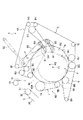
次に、図4に基づいてロールベーラ1の第2実施形態を説明する。本実施形態では、前述した第1実施形態と重複する部位についての説明は同符号を付すことにより省略する。   Next, a second embodiment of the roll baler 1 will be described with reference to FIG. In the present embodiment, the description of the same parts as those in the first embodiment will be omitted by attaching the same reference numerals.

本実施形態のロールベーラ1は、ベルト8が固定ローラ8Bと固定ローラ8Cとにわたって巻回して張設された成形室4を備えている。すなわち、ベルト8が固定ローラ7A、7Bよりも下流側に突出した部分がない成形室4を備えたものであり、投入口40への投入時にこぼれ落ちる被成形材料をベルト8によって成形室4に戻す機能を備えていないものである。そのため、本実施形態のロールベーラ1では、傾斜板A1の上端部A10をベルト7の外側面に近接する程度に延長することで、投入口40への投入時にこぼれ落ちる被成形材料を、傾斜板A1で受け止めることにより、戻し装置Aを経て成形室4に再び投入することができる。したがって、本実施形態のロールベーラによっても、前述の第1実施形態のロールベーラ1と同等の作用効果が期待できる。   The roll baler 1 of this embodiment includes a forming chamber 4 in which a belt 8 is wound around a fixed roller 8B and a fixed roller 8C. In other words, the belt 8 is provided with a molding chamber 4 having no portion protruding downstream from the fixed rollers 7A and 7B, and the molding material that spills when it is introduced into the inlet 40 is transferred to the molding chamber 4 by the belt 8. It does not have a function to return. Therefore, in the roll baler 1 of this embodiment, the upper end portion A10 of the inclined plate A1 is extended to the extent that it is close to the outer surface of the belt 7, so that the molding material that spills when being introduced into the inlet 40 is inclined plate A1. In this case, it can be recharged into the molding chamber 4 via the return device A. Therefore, the roll baler of this embodiment can be expected to have the same effect as the roll baler 1 of the first embodiment.

次に、図5及び図6に基づいてロールベーラ1の第3実施形態を説明する。本実施形態では、前述した第1実施形態と重複する部位についての説明は同符号を付すことにより省略する。   Next, a third embodiment of the roll baler 1 will be described based on FIGS. 5 and 6. In the present embodiment, the description of the same parts as those in the first embodiment will be omitted by attaching the same reference numerals.

本実施形態のロールベーラ1は、第1実施形態における固定ローラ6Kに代えて、第1可動ローラ6A、第2可動ローラ6Bに伴って長孔61に沿って移動する可変ローラの一例である第3可動ローラ6Lを備えたものである。第3可動ローラ6Lは、可動アーム60に軸支されるとともに、第2可動ローラ6Bが軸支された長孔61に、第2可動ローラ6Bよりも移動方向外側に軸支されている。また、第3可動ローラ6Lは、第1可動ローラ6A、第2可動ローラ6B間の隙間の中心線上に、且つ第1可動ローラ6A、第2可動ローラ6Bに近接するように配置されている。   The roll baler 1 of the present embodiment is an example of a variable roller that moves along the long hole 61 along with the first movable roller 6A and the second movable roller 6B instead of the fixed roller 6K in the first embodiment. A movable roller 6L is provided. The third movable roller 6L is pivotally supported by the movable arm 60, and is pivotally supported outside the second movable roller 6B in the moving direction by a long hole 61 in which the second movable roller 6B is pivotally supported. The third movable roller 6L is arranged on the center line of the gap between the first movable roller 6A and the second movable roller 6B and close to the first movable roller 6A and the second movable roller 6B.

このような、第1可動ローラ6A、第2可動ローラ6Bにベルト6の成形室4とは反対側の面を接触させて巻回し、第3可動ローラ6Lには、ベルト6の成形室4側の面を接触させて巻回することで、第1可動ローラ6A、第2可動ローラ6B間に形成される凹部63の深さを浅くすることができる。すなわち、凹部63の深さを浅くすることで、ロールベールR1、R2の成形中における被成形材料の凹部63への侵入量を少なくすることができるので、成形室4内の被成形材料の残留量を低減することができる。凹部63には、この凹部63に侵入しようとする被成形材料を阻んだり、ベルト6にこびりついた被成形材料をこそぎ落としたりするスクレーパ64が設けられており、このスクレーパ64によって、凹部63への被成形材料の侵入を抑制することができる。   The first movable roller 6A and the second movable roller 6B are wound with the surface opposite to the molding chamber 4 of the belt 6 in contact with the first movable roller 6A, and the third movable roller 6L is wound around the molding chamber 4 side of the belt 6. When the surface is brought into contact with each other and wound, the depth of the recess 63 formed between the first movable roller 6A and the second movable roller 6B can be reduced. That is, by reducing the depth of the recess 63, the amount of the molding material entering the recess 63 during molding of the roll bales R1 and R2 can be reduced, so that the molding material remaining in the molding chamber 4 remains. The amount can be reduced. The concave portion 63 is provided with a scraper 64 that prevents the molding material from entering the concave portion 63 or scrapes the molding material stuck to the belt 6. Intrusion of the molding material can be suppressed.

尚、本発明では、前述の第1実施形態〜第3実施形態のような、こぼれ落ちる被成形材料を再び成形室4に投入する機能を備えず、投入口40がロールベールR1、R2の中心位置P1、P2よりも上方に配置されたロールベーラ1も含み、このようなロールベーラ1によっても、被成形材料が成形室4に入らなくなる現象を防止することができるので、形状の良い締まったロールベールの成形、効率よいロールベールの成形をすることができる(図示せず)。   In the present invention, unlike the first to third embodiments described above, the material to be spilled is not provided with a function of again being fed into the molding chamber 4, and the inlet 40 is the center of the roll bales R1 and R2. The roll baler 1 disposed above the positions P1 and P2 is also included. The roll baler 1 can also prevent the phenomenon that the material to be molded does not enter the molding chamber 4, so that the roll bale with a good shape can be tightened. And efficient roll bale can be formed (not shown).

1:ロールベーラ(可変径ロールベーラ)
3:投入コンベア
4:成形室(ロールベール成形室)
6:ベルト
7:ベルト
8:ベルト
32:下流側端部
33:上流側端部
40:投入口
40A:下端部
6A:第1可動ローラ(可変ローラ)
6B:第2可動ローラ(可変ローラ)
6L:第3可動ローラ(可変ローラ)
7A:固定ローラ
8A:固定ローラ
R1:ロールベール
R2:ロールベール
63:凹部
64:スクレーパ
1: Roll baler (variable diameter roll baler)
3: Loading conveyor 4: Molding chamber (roll bale molding chamber)
6: Belt 7: Belt 8: Belt 32: Downstream end 33: Upstream end 40: Input port 40A: Lower end 6A: First movable roller (variable roller)
6B: Second movable roller (variable roller)
6L: Third movable roller (variable roller)
7A: Fixed roller 8A: Fixed roller R1: Roll bale R2: Roll bale 63: Concave portion 64: Scraper

Claims (5)

被成形材料を一つ又は複数のベルトを用いてロールベールに圧縮成形するロールベール成形室と、前記ロールベール成形室被成形材料を投入する投入コンベアとを備え、前記ロールベール成形室は、前記被成形材料の投入口と、前記ベルトが巻回され、成形される前記ロールベールの径に応じて、前記ロールベール成形室を拡開するように、該ロールベール成形室の中心からの位置を可変に軸支された可変ローラと、を備え、前記投入口を、該投入口の開口方向が前記可変ローラの可変方向と正対しない方向となるように設けたことを特徴とする可変径ロールベーラ。   A roll bale molding chamber for compressing and molding the molding material into a roll bale using one or a plurality of belts; and a roll conveyor molding chamber for charging the molding material, and the roll bale molding chamber includes: The position from the center of the roll bale molding chamber is set so as to expand the roll bale molding chamber in accordance with the diameter of the roll veil to be molded and the belt is wound and molded. A variable-diameter roll baler comprising: a variable roller that is variably supported by an axis; and the input port is provided such that an opening direction of the input port does not face a variable direction of the variable roller . 前記投入口が、成形される前記ロールベールの最大径の中心位置よりも上部に設けられていることを特徴とする請求項1記載の可変径ロールベーラ。   The variable diameter roll baler according to claim 1, wherein the charging port is provided above a center position of the maximum diameter of the roll bale to be molded. 前記投入コンベアの上流側端部を、前記投入口の下端部と重畳するように配置したことを特徴とする請求項1又は2記載の可変径ロールベーラ。   The variable diameter roll baler according to claim 1 or 2, wherein an upstream end portion of the charging conveyor is arranged so as to overlap with a lower end portion of the charging port. 前記可変ローラが、ロールベールの周方向に向かい合って軸支された第1可動ローラ及び第2可動ローラと、該第1可動ローラ及び第2可動ローラよりも前記可変方向外側に軸支された第3可動ローラと、を備え、前記ベルトを、前記第1可動ローラ及び前記第2可動ローラに対して、ロールベール成形室とは反対側の面を接触させて巻回するとともに、前記第3可動ローラに対して、前記ロールベール成形室側の面を接触させて巻回することで、前記ロールベール成形室と連通する凹部が構成され、前記凹部内に、該凹部内への前記被成形材料の侵入を抑制するスクレーパを備えたことを特徴とする請求項1乃至3いずれか1項記載の可変径ロールベーラ。   The variable roller includes a first movable roller and a second movable roller that are pivotally supported facing each other in a circumferential direction of the roll bale, and a first movable roller that is pivotally supported on the outer side in the variable direction than the first movable roller and the second movable roller. And a third movable roller, and the belt is wound around the first movable roller and the second movable roller with the surface opposite to the roll bale molding chamber in contact with the third movable roller. The roller bale molding chamber side surface is brought into contact with the roller and wound to form a recess communicating with the roll bale molding chamber, and the molding material into the recess is formed in the recess. The variable-diameter roll baler according to any one of claims 1 to 3, further comprising a scraper that suppresses intrusion. 複数のベルトを有するロールベール成形室を備えた可変径ロールベーラであって、前記ロールベール成形室の下部に配置される前記ベルトが、該ロールベール成形室を構成する他のローラより投入コンベア側に突出して設けられていることを特徴とする請求項2乃至4いずれか1項記載の可変径ロールベーラ。   A variable diameter roll baler provided with a roll bale forming chamber having a plurality of belts, wherein the belt arranged at the lower part of the roll bale forming chamber is closer to the input conveyor side than the other rollers constituting the roll bale forming chamber. The variable diameter roll baler according to any one of claims 2 to 4, wherein the roll baler is provided so as to protrude.
JP2011013868A 2011-01-26 2011-01-26 Variable diameter roll baler Expired - Fee Related JP5799456B2 (en)

Priority Applications (1)

Application Number Priority Date Filing Date Title
JP2011013868A JP5799456B2 (en) 2011-01-26 2011-01-26 Variable diameter roll baler

Applications Claiming Priority (1)

Application Number Priority Date Filing Date Title
JP2011013868A JP5799456B2 (en) 2011-01-26 2011-01-26 Variable diameter roll baler

Publications (2)

Publication Number Publication Date
JP2012152134A true JP2012152134A (en) 2012-08-16
JP5799456B2 JP5799456B2 (en) 2015-10-28

Family

ID=46834581

Family Applications (1)

Application Number Title Priority Date Filing Date
JP2011013868A Expired - Fee Related JP5799456B2 (en) 2011-01-26 2011-01-26 Variable diameter roll baler

Country Status (1)

Country Link
JP (1) JP5799456B2 (en)

Cited By (2)

* Cited by examiner, † Cited by third party
Publication number Priority date Publication date Assignee Title
KR101433298B1 (en) * 2012-11-19 2014-08-22 주식회사 라이브맥 Round baler having variable chamber for minute-cut plant
JP2015039363A (en) * 2013-08-23 2015-03-02 株式会社Ihiスター Roll baler

Citations (7)

* Cited by examiner, † Cited by third party
Publication number Priority date Publication date Assignee Title
JPS59191145U (en) * 1983-06-03 1984-12-18 金子農機株式会社 Roll baler
US4517795A (en) * 1979-11-28 1985-05-21 Deere & Company Bale-shape gauge for baler for forming cylindrical bales
JPS62148031U (en) * 1986-03-13 1987-09-18
JP2000139197A (en) * 1998-11-09 2000-05-23 Lely Welger Maschinenfabrik Gmbh Roll-type baler for agricultural crop
US6094900A (en) * 1998-05-08 2000-08-01 New Holland North America, Inc. Tension control system for round bale forming apparatus
JP2007267612A (en) * 2006-03-30 2007-10-18 Star Farm Machinery Mfg Co Ltd Roll baler
JP2010284108A (en) * 2009-06-11 2010-12-24 Ihi Star Machinery Corp Roll baler

Patent Citations (7)

* Cited by examiner, † Cited by third party
Publication number Priority date Publication date Assignee Title
US4517795A (en) * 1979-11-28 1985-05-21 Deere & Company Bale-shape gauge for baler for forming cylindrical bales
JPS59191145U (en) * 1983-06-03 1984-12-18 金子農機株式会社 Roll baler
JPS62148031U (en) * 1986-03-13 1987-09-18
US6094900A (en) * 1998-05-08 2000-08-01 New Holland North America, Inc. Tension control system for round bale forming apparatus
JP2000139197A (en) * 1998-11-09 2000-05-23 Lely Welger Maschinenfabrik Gmbh Roll-type baler for agricultural crop
JP2007267612A (en) * 2006-03-30 2007-10-18 Star Farm Machinery Mfg Co Ltd Roll baler
JP2010284108A (en) * 2009-06-11 2010-12-24 Ihi Star Machinery Corp Roll baler

Cited By (2)

* Cited by examiner, † Cited by third party
Publication number Priority date Publication date Assignee Title
KR101433298B1 (en) * 2012-11-19 2014-08-22 주식회사 라이브맥 Round baler having variable chamber for minute-cut plant
JP2015039363A (en) * 2013-08-23 2015-03-02 株式会社Ihiスター Roll baler

Also Published As

Publication number Publication date
JP5799456B2 (en) 2015-10-28

Similar Documents

Publication Publication Date Title
US3722197A (en) Method and machine for forming a large round bale of a fibrous material
US8627765B2 (en) Baling device to form bales of crop material
US11277971B2 (en) Agricultural baler including a bale chamber with a low traction rotary compression element
US5553446A (en) Apparatus for baling bulk fibrous material
JP5799456B2 (en) Variable diameter roll baler
CA2409550C (en) Round baler having simplified bale discharge structure
CA2410079C (en) Light discharge gate for large round baler
JPH08252025A (en) Bale diameter variable type roll baler
JP5863004B2 (en) Variable diameter roll baler
US10028438B2 (en) Pickup unit with a windrow conditioning roll for an agricultural baler
US20060243143A1 (en) Cylindrical baling press
CN116076247A (en) Adjustable storage feeding device
JP5373543B2 (en) Roll baler
US20110289882A1 (en) Mid-size baler
EP2570022A1 (en) A baler and a combined baler/bale wrapper
JP5373542B2 (en) Roll baler
JP4595049B2 (en) Roll baler
JP5476045B2 (en) Roll baler
JPS60262534A (en) Roll baler for weed
JP6210787B2 (en) Roll baler
JPH0923739A (en) Bale-molding sensor of roll baler
JP2001333630A (en) Bale forming apparatus for packing device
JPH08252026A (en) Twine feeder for roll baler
NZ727357B2 (en) Agricultural baler
EA008301B1 (en) Roll forming device

Legal Events

Date Code Title Description
A621 Written request for application examination

Free format text: JAPANESE INTERMEDIATE CODE: A621

Effective date: 20131122

A521 Written amendment

Free format text: JAPANESE INTERMEDIATE CODE: A821

Effective date: 20131122

A977 Report on retrieval

Free format text: JAPANESE INTERMEDIATE CODE: A971007

Effective date: 20140822

A131 Notification of reasons for refusal

Free format text: JAPANESE INTERMEDIATE CODE: A131

Effective date: 20140916

A521 Written amendment

Free format text: JAPANESE INTERMEDIATE CODE: A523

Effective date: 20141114

TRDD Decision of grant or rejection written
A01 Written decision to grant a patent or to grant a registration (utility model)

Free format text: JAPANESE INTERMEDIATE CODE: A01

Effective date: 20150714

A61 First payment of annual fees (during grant procedure)

Free format text: JAPANESE INTERMEDIATE CODE: A61

Effective date: 20150806

R150 Certificate of patent or registration of utility model

Ref document number: 5799456

Country of ref document: JP

Free format text: JAPANESE INTERMEDIATE CODE: R150

S111 Request for change of ownership or part of ownership

Free format text: JAPANESE INTERMEDIATE CODE: R313115

R350 Written notification of registration of transfer

Free format text: JAPANESE INTERMEDIATE CODE: R350

R250 Receipt of annual fees

Free format text: JAPANESE INTERMEDIATE CODE: R250

R250 Receipt of annual fees

Free format text: JAPANESE INTERMEDIATE CODE: R250

LAPS Cancellation because of no payment of annual fees