JP2012149935A - Residual fuel amount measuring apparatus - Google Patents
Residual fuel amount measuring apparatus Download PDFInfo
- Publication number
- JP2012149935A JP2012149935A JP2011007598A JP2011007598A JP2012149935A JP 2012149935 A JP2012149935 A JP 2012149935A JP 2011007598 A JP2011007598 A JP 2011007598A JP 2011007598 A JP2011007598 A JP 2011007598A JP 2012149935 A JP2012149935 A JP 2012149935A
- Authority
- JP
- Japan
- Prior art keywords
- float
- fuel
- fuel tank
- amount measuring
- flow path
- Prior art date
- Legal status (The legal status is an assumption and is not a legal conclusion. Google has not performed a legal analysis and makes no representation as to the accuracy of the status listed.)
- Granted
Links
Images


Abstract
Description
本発明は、燃料残量測定装置にかかり、特に、車両が車両前後方向または左右方向に傾斜した場合にも、燃料タンク内の燃料の液面高さを正確に検出できる燃料残量測定装置に関する。 The present invention relates to a fuel remaining amount measuring device, and more particularly to a fuel remaining amount measuring device that can accurately detect the level of fuel in a fuel tank even when the vehicle is tilted in the vehicle front-rear direction or the left-right direction. .
従来、自動車等の燃料タンクに設けられた燃料残量測定装置には種々の形式が存在するが、その一つとして車両上下方向に延設された縦長形状の検出電極(センサ)を用いて、燃料に検出電極が接する位置を検知し、液位を検出する構成が採用されている。 Conventionally, there are various types of fuel remaining amount measuring devices provided in a fuel tank of an automobile or the like, and as one of them, using a vertically long detection electrode (sensor) extending in the vehicle vertical direction, A configuration is employed in which the position where the detection electrode contacts the fuel is detected to detect the liquid level.
例えば検出部が常に液中に浸漬される基準電極と、常に液外にある気層電極と、液面と交差する液面電極とを組み合わせ、電極と液との接触/非接触による静電容量の変化から液面を検出する構成が提案されている(特許文献1)。 For example, a combination of a reference electrode in which the detection unit is always immersed in the liquid, a gas-phase electrode that is always outside the liquid, and a liquid surface electrode that intersects the liquid surface, and the capacitance due to contact / non-contact between the electrode and the liquid The structure which detects a liquid level from the change of is proposed (patent document 1).
しかし、図8に示すように燃料タンク100の形状によっては燃料タンク100の中央(平面視)近傍に挿入口122が設けられているなどの理由で、満タン時の液面Fが燃料タンク100の中央に存在せず、液位センサ114を燃料タンク100の中央に設置すると満タン時の液面を検出できない場合が考えられる。
However, depending on the shape of the
このために、図9に示すように、燃料タンク100の中央を避けて前後方向、左右方向などの端部に液位センサ114を設置すると、車体の傾斜時やコーナリング時など燃料タンクの内部で液面が傾斜した際に、端部に設けられた液位センサ114では正確な液面検知を行うことができず、しかも大きなメータ針振れが生じるという問題があった。
For this reason, as shown in FIG. 9, if the
この問題を回避した燃料タンクの液面検出器としては、たとえば、タンクに連通する液面モニタ室を形成する筐体と、前記液面も似た室の液面高さを検出する検出手段と、前記液面モニタ室と前記タンクとの間の連通路を開閉する開閉手段とからなり、前記開閉手段は可動錐体と、前位可動錐体が基準位置から変位した時前記連通路を閉塞する開閉弁機構とからなる液面検出器がある(特許文献2)。 As a liquid level detector for a fuel tank that avoids this problem, for example, a housing that forms a liquid level monitor chamber that communicates with the tank, and a detection means that detects the liquid level of a chamber similar to the liquid level, And an opening / closing means for opening / closing a communication path between the liquid level monitoring chamber and the tank. The opening / closing means closes the communication cone and the communication path when the front movable cone is displaced from a reference position. There is a liquid level detector comprising an open / close valve mechanism (Patent Document 2).
しかしながら、前記液面検出器は、弁機構が弁体、球状錐体、およびハウジングから構成されているため、構造が複雑であるという問題があった。 However, the liquid level detector has a problem that its structure is complicated because the valve mechanism is composed of a valve body, a spherical cone, and a housing.
本発明は、上記問題を解決すべく成されたもので、構造が単純であって、しかも車両が車両前後方向または左右方向に傾斜した場合にも、燃料タンク内の燃料の液面高さを正確に検出できる燃料残量測定装置の提供を目的とする。 The present invention has been made to solve the above problem, and has a simple structure. Even when the vehicle is tilted in the vehicle front-rear direction or the left-right direction, the liquid level of the fuel in the fuel tank can be reduced. An object of the present invention is to provide a fuel remaining amount measuring device that can be accurately detected.
請求項1に記載の発明は、車両に備えられ、燃料が貯留される燃料タンクの底面に立設された筒状の本体部と、前記本体部の内部に配設され、前記本体内部の燃料の液位を測定する液位センサと、前記本体部の下端部に設けられ、前記本体部と前記燃料タンクとを連通する流路を有するフロート収容室と、前記フロート収容室に移動または回転可能に収容され、前記燃料タンクの水平からの傾きが所定角度以上になると前記フロート収容室内において移動または回転して前記フロート収容室の流路を閉止するフロートと、を備える燃料残量測定装置に関する。 The invention according to claim 1 is provided in a vehicle and has a cylindrical main body portion standing on a bottom surface of a fuel tank in which fuel is stored, a fuel disposed inside the main body portion, and disposed inside the main body portion. A liquid level sensor for measuring the liquid level of the liquid, a float storage chamber provided at a lower end portion of the main body, and having a flow path communicating the main body with the fuel tank; and movable or rotatable to the float storage chamber And a float that moves or rotates in the float housing chamber to close a flow path of the float housing chamber when the inclination of the fuel tank from a horizontal angle exceeds a predetermined angle.
前記燃料残量測定装置においては、車両が傾斜していないときは、前記フロート収容室の流路は開成された状態にあるから、燃料タンクと本体部とは前記フロート収容室の流路によって連通されている。したがって、燃料タンク内と本体部の内部とで燃料の液位が同一になるから、液位センサで測定された燃料の液位はそのまま燃料タンク内の液位となる。 In the fuel remaining amount measuring device, when the vehicle is not inclined, the flow path of the float accommodation chamber is in an open state, so that the fuel tank and the main body communicate with each other through the flow path of the float accommodation chamber. Has been. Accordingly, the fuel level in the fuel tank is the same as that in the main body, so that the fuel level measured by the level sensor is the same as the level in the fuel tank.
ここで、燃料タンクが水平から所定の角度以上傾斜すると、前記フロート収容室内においてフローとが移動または回転して前記流路が閉止するから、燃料タンクと本体部との間の燃料の流れが実質的に断たれる。したがって、本体部においては、燃料タンク内の液面が傾斜することによる液位の変動が抑制される Here, when the fuel tank is inclined from the horizontal by a predetermined angle or more, the flow moves or rotates in the float housing chamber and the flow path is closed, so that the flow of fuel between the fuel tank and the main body is substantially reduced. Refused. Therefore, in the main body, the fluctuation of the liquid level due to the inclination of the liquid level in the fuel tank is suppressed.
請求項2に記載の発明は、前記フロートが、中心点を通る直線状の流路が形成され、前記流路の一端部近傍に錘が設けられた球状フロートであり、前記フロート収容室における流路が、前記球状フロートの回転角が前記所定角度より小さいときに前記球状フロートの流路と連通するように形成されている請求項1に記載の燃料残量測定装置に関する。 According to a second aspect of the present invention, the float is a spherical float in which a linear flow path passing through a center point is formed, and a weight is provided in the vicinity of one end of the flow path. The fuel remaining amount measuring apparatus according to claim 1, wherein a path is formed so as to communicate with a flow path of the spherical float when a rotation angle of the spherical float is smaller than the predetermined angle.
前記燃料残量測定装置においては、車両が傾斜していないときは、前記フロート収容室の流路と前記球状フロートの流路とが連通しているから、燃料タンクと本体部とは連通した状態にある。 In the fuel remaining amount measuring device, when the vehicle is not inclined, the flow path of the float housing chamber and the flow path of the spherical float are in communication with each other, so that the fuel tank and the main body are in communication with each other. It is in.
ここで、燃料タンクが水平から所定の角度以上傾斜すると、前記フロート収容室内において前記球状フロートが中心周りに回転して前記フロート収容室の流路が前記球状フロートによって閉止される。これによって本体部と燃料タンクとの間の連通が断たれるから、本体部においては、燃料タンク内の液面が傾斜することによる液位の変動が抑制される。 Here, when the fuel tank is inclined from the horizontal by a predetermined angle or more, the spherical float rotates around the center in the float accommodating chamber, and the flow path of the float accommodating chamber is closed by the spherical float. As a result, the communication between the main body and the fuel tank is interrupted, so that fluctuations in the liquid level due to the inclination of the liquid level in the fuel tank are suppressed in the main body.
請求項3に記載の発明は、前記球状フロートが、燃料の比重に近似する比重を有する材料から形成されている請求項2に記載の燃料残量測定装置に関する。 A third aspect of the present invention relates to the fuel remaining amount measuring apparatus according to the second aspect, wherein the spherical float is made of a material having a specific gravity approximate to the specific gravity of the fuel.
前記燃料残量測定装置においては、球状フロートが燃料の比重に近似する比重を有する材料から形成されているから、球状フロートが燃料から受ける浮力を極小にできる。したがって、前記浮力によって球状フロートがフロート収容室の天井面に押圧されることによる摺動抵抗を低減できる。 In the fuel remaining amount measuring apparatus, since the spherical float is made of a material having a specific gravity that approximates the specific gravity of the fuel, the buoyancy that the spherical float receives from the fuel can be minimized. Therefore, sliding resistance due to the spherical float being pressed against the ceiling surface of the float housing chamber by the buoyancy can be reduced.
請求項4の発明は、前記フロートが、厚さ方向に沿って1または複数の流路が形成された板状フロートであり、前記フロート収容室が、前記板状フロートを面方向に沿って移動可能に収容するとともに、前記フロート収容室の流路が、前記燃料タンクの傾斜が前記所定角度以下のときに前記板状フロートの流路と連通するように形成されている請求項1に記載の燃料残量測定装置に関する。 According to a fourth aspect of the present invention, the float is a plate-like float in which one or a plurality of flow paths are formed along the thickness direction, and the float housing chamber moves along the surface direction of the plate-like float. 2. The storage according to claim 1, wherein the flow path of the float storage chamber is configured to communicate with the flow path of the plate-like float when the inclination of the fuel tank is equal to or less than the predetermined angle. The present invention relates to a fuel remaining amount measuring device.
前記燃料残量測定装置においては、車両が傾斜していないときは、前記フロート収容室の流路と前記板状フロートの流路とが連通しているから、燃料タンクと本体部とは連通した状態にある。 In the fuel remaining amount measuring device, when the vehicle is not inclined, the flow path of the float housing chamber and the flow path of the plate-like float communicate with each other, so that the fuel tank and the main body communicate with each other. Is in a state.
ここで、車両を傾斜地に駐車した場合のように、燃料タンクが所定の角度以上傾斜すると、前記板状フロートは、前記フロート収容室内において燃料から受ける浮力によって面方向に沿って移動することにより、前記フロート収容室の流路が前記板状フロートによって閉止される。これによって本体部と燃料タンクとの間の連通が断たれるから、本体部においては、燃料タンク内の液面が傾斜することによる液位の変動が抑制される。 Here, when the fuel tank is inclined at a predetermined angle or more as in the case where the vehicle is parked on a sloping ground, the plate-like float moves along the surface direction by the buoyancy received from the fuel in the float housing chamber, The flow path of the float storage chamber is closed by the plate float. As a result, the communication between the main body and the fuel tank is interrupted, so that fluctuations in the liquid level due to the inclination of the liquid level in the fuel tank are suppressed in the main body.
請求項5の発明は、前記フロートの上面が上方に向かって凹陥した球面状とされ、前記フロート収容室の天井面は、前記フロートの上面の曲率に対応し、且つ上方に向かって凹陥した球面状とされている請求項4に記載の燃料残量測定装置に関する。 According to a fifth aspect of the present invention, the upper surface of the float has a spherical shape recessed upward, and the ceiling surface of the float accommodation chamber corresponds to the curvature of the upper surface of the float and is concaved upward. The present invention relates to a fuel remaining amount measuring device according to claim 4.
前記燃料残量測定装置においては、燃料タンクが所定の角度以上傾斜すると、前記板状フロートは、前記フロート収容室内において、前記板状フロートの上面がその一部をなす仮想球体の中心点の周りを回転する運動をする。これにより、前記フロート収容室の流路が前記板状フロートによって閉止される。 In the fuel remaining amount measuring device, when the fuel tank is inclined at a predetermined angle or more, the plate-like float is around the center point of the virtual sphere in which the upper surface of the plate-like float forms a part in the float housing chamber. Make a rotating motion. Thereby, the flow path of the float accommodation chamber is closed by the plate-like float.
請求項1の発明によれば、構造が単純であって、しかも車両が車両前後方向または左右方向に傾斜した場合にも、燃料タンク内の燃料の液面高さを正確に検出できる燃料残量測定装置が提供される。 According to the first aspect of the present invention, the remaining amount of fuel that has a simple structure and that can accurately detect the level of the fuel in the fuel tank even when the vehicle is tilted in the front-rear direction or the left-right direction of the vehicle. A measuring device is provided.
請求項2の発明によれば、フロートとして球状フロートを用いているから、フロート収容室内部におけるフロートの動作がよりスムースであり、車両が車両前後方向または左右方向に傾斜した場合に本体部と燃料タンクとの連通をより確実に遮断できる燃料残量測定装置が提供される。 According to the second aspect of the present invention, since the spherical float is used as the float, the operation of the float in the float accommodation chamber is smoother, and the main body and the fuel when the vehicle tilts in the vehicle front-rear direction or the left-right direction. Provided is a fuel remaining amount measuring device that can more reliably block communication with a tank.
請求項3の発明によれば、球状フロートと燃料との比重差が大きな燃料残量測定装置と比較して球状フロートがフロート収容室内で回転するときの摺動抵抗がより小さな燃料残量測定装置が提供される。 According to the invention of claim 3, the fuel remaining amount measuring device having a smaller sliding resistance when the spherical float rotates in the float housing chamber as compared with the fuel remaining amount measuring device having a large specific gravity difference between the spherical float and the fuel. Is provided.
請求項4の発明によれば、フロートとして球状フロートを有する燃料残量測定装置と比較して構成のより単純な燃料残量測定装置が提供される。 According to the fourth aspect of the present invention, there is provided a fuel remaining amount measuring device having a simpler structure as compared with a fuel remaining amount measuring device having a spherical float as a float.
請求項5の燃料残量測定装置においては、燃料タンクが所定の角度以上傾斜すると、前記板状フロートは、前記フロート収容室内において、前記板状フロートの上面がその一部をなす仮想球体の中心点の周りを回転する運動をする。 6. The fuel remaining amount measuring apparatus according to claim 5, wherein when the fuel tank is inclined at a predetermined angle or more, the plate-like float is centered on a virtual sphere in which the upper surface of the plate-like float forms a part in the float housing chamber. Move around the point.
したがって、請求項5の発明によれば、前記板状フロートが面方向に沿って移動する形態の燃料残量測定装置と比較して板状フロートが移動する際の抵抗が少ない燃料残量測定装置が提供される。 Therefore, according to the fifth aspect of the present invention, the remaining fuel amount measuring device with less resistance when the plate-like float moves compared to the remaining fuel amount measuring device in which the plate-like float moves along the surface direction. Is provided.
1.実施形態1
以下、本発明の燃料残量測定装置を備える燃料ランクの一例について図面を用いて説明する。図1以下において矢印UPは車体上方方向を示す。
1. Embodiment 1
Hereinafter, an example of a fuel rank provided with the fuel remaining amount measuring device of the present invention will be described with reference to the drawings. In FIG. 1 and subsequent figures, the arrow UP indicates the upward direction of the vehicle body.
燃料タンク10は、図1に示すように略箱形形状とされた容器であり、設置される車体などの形状や部品配置によってその形状が決定される。また燃料タンク10は燃料(ガソリンなど)による腐食への耐性、機械的強度、耐衝撃性や衝突の際の安全性などを考慮して素材が選定される。
The
燃料タンク10の車体上側にはポンプモジュール等の取付口22が設けられており、取付口22を外側から閉塞する蓋部28で、内部の燃料が外へ漏れ出さないように密閉される。車両上方に筒状に突出した取付口22は蓋部28で密閉され、取付口22の外周面に設けられた雄ネジと螺号する螺子蓋120で蓋部28が固定される。
A mounting
このとき、取付口22が箱状の燃料タンク10から突出していると、車体に組み付ける際にスペース効率が低下する虞があるので、取付口22を燃料タンク10の内側に沈めるように設ける方が望ましい。この場合、取付口22および螺子蓋120をクリアできる空間を燃料タンク10の内部に設ける必要がある。
At this time, if the mounting
これにより燃料タンク10の車体上側面は外面が凹んだ凹部24が形成されており、凹部24の内側は燃料タンク10内部の車体下側に向けて突出した凸部26として形成されている。このため燃料タンク10の内部に燃料を充填していくと液面Fは凸部26の高さを超え、凸部26は燃料に浸漬する。
Accordingly, a
燃料タンク10は一般的に鋼板または樹脂で形成され、図1に示すように車体上側面に凹凸を設けるなどの方法で、ベーパー層を確保している。すなわち、揮発性を備えた燃料は外気温やエンジンなどの熱により蒸発し、燃料タンク10内の空隙に揮発ガス(ベーパー)となって充満する。このとき燃料をタンク全体に満たしてしまった場合、発生した燃料の揮発ガスは逃げ場を失い、燃料タンク10内が加圧される。これを防ぐため、ある程度の空隙(ベーパー層)を燃料タンク10内の上部に設定することで、揮発ガスの圧力の逃げ場を確保している。
The
また、上記のようにベーパー層を確保している燃料タンク10では、燃料温度の上下(気温、路面や排気管などからの熱の影響)と燃料消費により、加圧と減圧が絶えず繰り返され、機械的ストレスが印加され続ける。このため、燃料タンク10の上面を複雑な凹凸形状にする事は燃料タンク10自体の機械的強度を増し、内部圧力の変化に対する対策とする意味も備わっている。
Further, in the
また燃料タンク10の内部には図示しないポンプユニットが設けられ、内部の燃料をポンプで汲み出し、図示しない燃料ホースで外部へ送り出す構成とされていてもよい。
Further, a pump unit (not shown) may be provided inside the
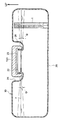
図1に示すように、燃料タンク10の底面20における凸部26をクリアできる位置から車両上方に向かって本発明の燃料残量測定装置の一例としての液面計1が立設されている。液面計1は、図1に示すように、上端が、燃料タンク10が水平のときの満タン時の液面Fよりも車両上方に突出する高さとされている。
As shown in FIG. 1, a liquid level gauge 1 as an example of the fuel remaining amount measuring device of the present invention is erected from a position where the
液面計1は、図2に示すように、円筒状の本体部11と、本体部11の内部に設けられた液位センサ14と、本体部11の下端部に設けられ、後述する球状フロート12を中心点の周りに回転自在に収容するフロート収容室13と、を備える。本体部における液位センサ14が設けられた部分である液位測定室15と、フロート収容室13と液位測定室15とを区画する隔壁16と、を備える。
As shown in FIG. 2, the liquid level gauge 1 is provided with a cylindrical
球状フロート12は、全体としてポリアセタール樹脂やポリフェニレンスルフィド樹脂、脂肪族ポリアミド樹脂など、比重が燃料とほぼ同一であり、且つ燃料で膨潤しない樹脂材料から形成されている。そして、図2に示すように、中心点を通る直線状の流路12Aが形成され、流路12Aの一端部近傍には錘12Bが埋包されている。
The
フロート収容室13の車両下方側は導通孔18Aを設けた蓋18で塞がれている。
The vehicle lower side of the
隔壁16には、水平からの燃料タンク10の傾きθが、図1に示すように燃料計の針の振れが許容できる角度である許容角度φ以下のときに球状フロート12の流路12Aと連通する流路17が穿設されている。
The
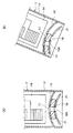
液位センサ14は、例えば図3(A)に示すように車両上下方向を長手とする樹脂フィルムなど折り曲げ可能な絶縁体で形成されたベース14Eの表面に電極14Dが設けられた構造とされ、電極14Dのうちガソリンなどの燃料と接している部分の長さと、空気と接している部分の長さとによって変動する電気容量などから、燃料タンク10の内部に残った燃料の残量を検出する静電容量センサである。
The
液位センサ14において、電極14Dは、常に燃料に浸かっている燃料リファレンス測定部14Aと、満タン時の液面Fよりも常に上方に位置するように形成された基準測定部14Cと、燃料リファレンス測定部14Aと基準測定部14Cとの間に位置し、燃料タンク10の燃料の液位を測定する液位測定部14Bとに区分されている。
In the
電極14Dは、図3(B)に示すように、燃料リファレンス測定部14Aと液位測定部14Bと基準測定部14Cとを接続する共通リード線14Fと、燃料リファレンス測定部14Aと液位測定部14Bと基準測定部14Cとの夫々における静電容量を出力する出力側リード線14Gと、共通リード線14Fから所定の間隔で水平方向に突設された櫛状電極14Hと、出力側リード線14Gから所定の間隔で水平方向に突設された櫛状電極14Iと、を有する。櫛状電極14Hと櫛状電極14Iとは交互に配列されている。
As shown in FIG. 3B, the
電気的に液面高さを検出する方法には、たとえば電極14D間の静電容量を測定する方法がある。燃料タンクの燃料が使い尽くされると、電極14Dの間の空間は、それまで燃料によって占められていたものが空気によって占められるようになるため、静電容量は減少する。従って、静電容量の減少を検出することにより、燃料が空になったことを検出できる。このとき、予め空気中に設けられた基準測定部14Cと、常に液中に存在する燃料リファレンス測定部14Aとで検出された値を基準として、測定値を比較することでさらに正確な検出を行うことができる。
As a method of electrically detecting the liquid level, for example, there is a method of measuring the capacitance between the
電極14Dにおける共通リード線14Fおよび出力側リード線14Gは、液位センサ14の端部に設けられた端子14Jで外部と電気的に接続され、例えば外部に設けられた電気回路にて検出された液位は燃料量情報として燃料タンク10の外へ伝達される。
The
以下、液面計1の作用について図4を用いて説明する。
球状フロート12は、フロート収容室13内に、中心点の周りに自由に回転可能に収容されている。そして、流路12Aの一端近傍には錘12Bが埋包されている。したがって、図4(A)および図4(B)に示すように、球状フロート12は、フロート収容室13の内部で、常に錘12Bが埋包された側が下側に位置するように回転するから、流路12Aは常に垂直方向を向く。
Hereinafter, the operation of the liquid level gauge 1 will be described with reference to FIG.
The
したがって、燃料タンク10が水平のときは、図4(A)に示すように本体部11の隔壁16に設けられた流路17と球状フロート12の流路12Aが連通するから、フロート収容室13を介して液位測定室15と燃料タンク10内部とが連通する。これにより、液面計1における燃料の液位と燃料タンク10内の燃料の液位とは等しくなる。
Therefore, when the
車両が何らかの理由で傾斜して燃料タンク10が水平から傾きθだけ傾くと、液面計1の本体部11も図4(A)の状態から角度θだけ傾く。一方、球状フロート12は、フロート収容室13の内部で、流路12Aが常に垂直方向を向くように回転する。したがって、燃料タンク10の傾きθが許容角度φを超えると、図4(B)に示すように、隔壁16の流路17が球状フロート12によって閉じられて液位測定室15と燃料タンク10内部との連通が断たれる。これにより、燃料タンク10が傾いても、液位測定室15内部の燃料の液面は、燃料タンク10の傾きθが許容角度φを超えないときの高さに保持される。
When the vehicle inclines for some reason and the
2.実施形態2
以下、本発明の燃料残量測定装置を備える燃料ランクの別の例について図面を用いて説明する。図5以下において図1〜図4と同一の符号は特に断らない限り前記符号が図1〜図4において示すのと同一の構成要素を示す。
2.
Hereinafter, another example of the fuel rank provided with the fuel remaining amount measuring device of the present invention will be described with reference to the drawings. In FIG. 5 and subsequent figures, the same reference numerals as those in FIGS. 1 to 4 indicate the same components as those shown in FIGS.
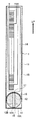
図5に示すように、燃料タンク10の底面20における凸部26をクリアできる位置から車両上方に向かって本発明の燃料残量測定装置の別の例としての液面計2が立設されている。液面計2は、図5に示すように、上端が、燃料タンク10が水平のときの満タン時の液面Fよりも車両上方に突出する高さとされている。
As shown in FIG. 5, a
液面計1は、図6に示すように、円筒状の本体部11と、本体部11の内部に設けられた液位センサ14と、本体部11の下端部に設けられ、後述する板状フロート19を収容するフロート収容室13と、本体部における液位センサ14が設けられた部分である液位測定室15と、フロート収容室13と液位測定室15とを区画する隔壁16と、を備える。
As shown in FIG. 6, the liquid level gauge 1 is provided at a cylindrical
隔壁16は、上方に突出する球面状とされている。隔壁16の頂部には流路17が開口している。
The
フロート収容室13には、隔壁16に対応する上方に突出する球面上とされた、フロート19を面方向にガイドするためのガイド21が設けられている。
The
板状フロート19は、フロート収容室13の内径よりも小さな外径を有する略円板状であり、燃料よりも比重の小さな材料で形成されている。そして、上面は、隔壁16の下側の面の形状に対応する球面状とされ、下面はガイド21の上面に対応する球面状とされている。板状フロート19の中央部には、厚さ方向に沿って流路19Aが形成されている。
The plate-
液位センサ14については実施形態1のところで述べたとおりである。
The
以下、液面計2の作用について図5を用いて説明する。
上述のように板状フロート19は、燃料よりも比重の小さな材料で形成されているとともに、フロート収容室13の内径よりも小さな外径を有する。したがって、図7の(A)に示すように、燃料からの浮力によってフロート収容室13内において、上面が隔壁16の下面に接した状態で浮いている。
Hereinafter, the operation of the
As described above, the plate-
したがって、燃料タンク10が水平のときは、図7(A)に示すように板状フロート19と流路19Aと隔壁16の流路17とが連通した状態になるから、液面計2の液位測定室15と燃料タンク10の内部とが連通するから、液面計2における燃料の液位と燃料タンク10内の燃料の液位とは等しくなる。
Therefore, when the
車両が何らかの理由で傾斜して燃料タンク10も水平から傾きθだけ傾くと、液面計2の本体部11も図7(A)の状態から角度θだけ傾く。一方、板状フロート19は、隔壁16の下面に沿ってフロート収容室13の内部を上方に移動することにより、フロート収容室13の中央部から側壁に向かって移動する。したがって、燃料タンク10の傾きθが許容角度φを超えると、図7(B)に示すように、隔壁16の流路17が板状フロート19によって閉じられて液位測定室15と燃料タンク10内部との連通が断たれる。これにより、燃料タンク10が傾いても、液位測定室15内部の燃料の液面は、燃料タンク10の傾きθが許容角度φを超えないときの高さに保持される。
When the vehicle inclines for some reason and the
実施形態2における液面計2は、フロートとして均質な材料からなる板状フロート19を用いているから、フロートとして球状フロート12を用いる実施形態1の液面計1と比較してフローとの構成が単純化できる。
Since the
1 液面計
2 液面計
10 燃料タンク
11 本体部
12 球状フロート
12A 流路
12B 錘
13 フロート収容室
14 液位センサ
14A 燃料リファレンス測定部
14B 液位測定室
14C 基準測定部
14D 電極
14E ベース
14F 共通リード線
14G 出力側リード線
14H 櫛状電極
14I 櫛状電極
14J 端子
15 液位測定室
16 隔壁
17 流路
19 板状フロート
19A 流路
20 底面
DESCRIPTION OF SYMBOLS 1
Claims (5)
前記本体部の内部に配設され、前記本体部の内部の燃料の液位を測定する液位センサと、
前記本体部の下端部に設けられ、前記本体部と前記燃料タンクとを連通する流路を有するフロート収容室と、
前記フロート収容室に移動または回転可能に収容され、前記燃料タンクの水平からの傾きが所定角度以上になると前記フロート収容室内において移動または回転して前記フロート収容室の流路を閉止するフロートと、
を備える燃料残量測定装置。 A cylindrical main body provided on a vehicle and standing on the bottom of a fuel tank in which fuel is stored;
A liquid level sensor which is disposed inside the main body and measures the liquid level of the fuel inside the main body;
A float housing chamber provided at a lower end of the main body, and having a flow path communicating the main body with the fuel tank;
A float that is movably or rotatably housed in the float housing chamber, and that moves or rotates in the float housing chamber to close the flow path of the float housing chamber when the inclination of the fuel tank from a horizontal angle exceeds a predetermined angle;
A fuel remaining amount measuring device.
前記フロート収容室は、球状フロートを中心周りに回転可能に収容すると共に、前記フロート収容室における流路は、前記球状フロートの回転格が前記所定角度より小さいときに前記球状フロートの流路と連通するように形成されている請求項1に記載の燃料残量測定装置。 The float is a spherical float in which a linear flow path passing through a center point is formed, and a weight is provided near one end of the flow path,
The float accommodation chamber accommodates the spherical float so as to be rotatable around the center, and the flow path in the float accommodation chamber communicates with the flow path of the spherical float when the rotational rating of the spherical float is smaller than the predetermined angle. The fuel remaining amount measuring device according to claim 1, wherein the fuel remaining amount measuring device is configured to do so.
前記フロート収容室は、前記板状フロートを面方向に沿って移動可能に収容するとともに、前記フロート収容室の流路は、前記燃料タンクの傾斜が前記所定角度以下のときに前記板状フロートの流路と連通する
請求項1に記載の燃料残量測定装置。 The float is a plate-like float in which one or a plurality of flow paths are formed along the thickness direction,
The float accommodation chamber accommodates the plate-like float so as to be movable along a plane direction, and the flow path of the float accommodation chamber is configured so that the inclination of the fuel tank is equal to or less than the predetermined angle. The fuel remaining amount measuring device according to claim 1, wherein the fuel remaining amount measuring device communicates with the flow path.
Priority Applications (1)
| Application Number | Priority Date | Filing Date | Title |
|---|---|---|---|
| JP2011007598A JP5561181B2 (en) | 2011-01-18 | 2011-01-18 | Fuel level measuring device |
Applications Claiming Priority (1)
| Application Number | Priority Date | Filing Date | Title |
|---|---|---|---|
| JP2011007598A JP5561181B2 (en) | 2011-01-18 | 2011-01-18 | Fuel level measuring device |
Publications (2)
| Publication Number | Publication Date |
|---|---|
| JP2012149935A true JP2012149935A (en) | 2012-08-09 |
| JP5561181B2 JP5561181B2 (en) | 2014-07-30 |
Family
ID=46792320
Family Applications (1)
| Application Number | Title | Priority Date | Filing Date |
|---|---|---|---|
| JP2011007598A Expired - Fee Related JP5561181B2 (en) | 2011-01-18 | 2011-01-18 | Fuel level measuring device |
Country Status (1)
| Country | Link |
|---|---|
| JP (1) | JP5561181B2 (en) |
Cited By (1)
| Publication number | Priority date | Publication date | Assignee | Title |
|---|---|---|---|---|
| KR20220162355A (en) | 2021-06-01 | 2022-12-08 | 현대건설기계 주식회사 | Detecting device for residual fuel of fuel tank |
Citations (2)
| Publication number | Priority date | Publication date | Assignee | Title |
|---|---|---|---|---|
| JPS53147155U (en) * | 1977-04-22 | 1978-11-20 | ||
| JPS6372524U (en) * | 1986-10-29 | 1988-05-14 |
-
2011
- 2011-01-18 JP JP2011007598A patent/JP5561181B2/en not_active Expired - Fee Related
Patent Citations (2)
| Publication number | Priority date | Publication date | Assignee | Title |
|---|---|---|---|---|
| JPS53147155U (en) * | 1977-04-22 | 1978-11-20 | ||
| JPS6372524U (en) * | 1986-10-29 | 1988-05-14 |
Cited By (1)
| Publication number | Priority date | Publication date | Assignee | Title |
|---|---|---|---|---|
| KR20220162355A (en) | 2021-06-01 | 2022-12-08 | 현대건설기계 주식회사 | Detecting device for residual fuel of fuel tank |
Also Published As
| Publication number | Publication date |
|---|---|
| JP5561181B2 (en) | 2014-07-30 |
Similar Documents
| Publication | Publication Date | Title |
|---|---|---|
| US20070205907A1 (en) | Switch assembly and system for high-level monitoring | |
| US6029514A (en) | Device for measuring the volume of liquid in a container | |
| EP2962076B1 (en) | Reservoir assembly for storing hydrogen peroxide for use with a hydrogen peroxide vaporizer in association with a filler | |
| JP2017198157A (en) | Fuel supply system | |
| JP5561181B2 (en) | Fuel level measuring device | |
| JP2016088167A (en) | Fluid storage device | |
| KR20160024190A (en) | Apparatus for sensing fuel level | |
| KR20210032819A (en) | Fuel tank with level measurement | |
| JP4005569B2 (en) | Fuel supply device | |
| KR101145607B1 (en) | Liquid level detecting apparatus of high-pressure vessel | |
| JP2014006128A (en) | Gas sensor and gas sensing method | |
| JP2017075853A (en) | Liquid level sensor | |
| JP5741399B2 (en) | Fuel tank structure | |
| JP2014142240A (en) | Liquid level measuring apparatus | |
| JP5609756B2 (en) | Liquid level detector | |
| KR20230081145A (en) | Apparatus for measuring amount of fuel | |
| JP5510344B2 (en) | Fuel level measuring device | |
| JP5626186B2 (en) | Fuel tank structure | |
| JP2018017661A (en) | Liquid surface level detector | |
| JP2009115749A (en) | Water gauge | |
| JP2014145630A (en) | Fuel tank structure | |
| RU2603948C1 (en) | Device and method for determining liquid density | |
| JP6057576B2 (en) | Content capacity estimation apparatus and content capacity estimation system having the same | |
| KR101491882B1 (en) | Manless watering device | |
| JP2013116673A (en) | Fuel tank structure |
Legal Events
| Date | Code | Title | Description |
|---|---|---|---|
| A621 | Written request for application examination |
Free format text: JAPANESE INTERMEDIATE CODE: A621 Effective date: 20130704 |
|
| A977 | Report on retrieval |
Free format text: JAPANESE INTERMEDIATE CODE: A971007 Effective date: 20140213 |
|
| A131 | Notification of reasons for refusal |
Free format text: JAPANESE INTERMEDIATE CODE: A131 Effective date: 20140218 |
|
| A521 | Written amendment |
Free format text: JAPANESE INTERMEDIATE CODE: A523 Effective date: 20140421 |
|
| TRDD | Decision of grant or rejection written | ||
| A01 | Written decision to grant a patent or to grant a registration (utility model) |
Free format text: JAPANESE INTERMEDIATE CODE: A01 Effective date: 20140513 |
|
| A61 | First payment of annual fees (during grant procedure) |
Free format text: JAPANESE INTERMEDIATE CODE: A61 Effective date: 20140526 |
|
| LAPS | Cancellation because of no payment of annual fees |