JP2012149083A - Stable and efficient electroluminescent material - Google Patents
Stable and efficient electroluminescent material Download PDFInfo
- Publication number
- JP2012149083A JP2012149083A JP2012076267A JP2012076267A JP2012149083A JP 2012149083 A JP2012149083 A JP 2012149083A JP 2012076267 A JP2012076267 A JP 2012076267A JP 2012076267 A JP2012076267 A JP 2012076267A JP 2012149083 A JP2012149083 A JP 2012149083A
- Authority
- JP
- Japan
- Prior art keywords
- ring
- alkyl
- aryl
- metal
- independently
- Prior art date
- Legal status (The legal status is an assumption and is not a legal conclusion. Google has not performed a legal analysis and makes no representation as to the accuracy of the status listed.)
- Granted
Links
- 0 C*c1*(C(*)(C*2)Cc3c2c(*)c(*)c(*)c3-2)c-2c(*)c(O)c1*(C)* Chemical compound C*c1*(C(*)(C*2)Cc3c2c(*)c(*)c(*)c3-2)c-2c(*)c(O)c1*(C)* 0.000 description 14
- JSYRVFMYSXJSPK-UHFFFAOYSA-N Cc1ccc(-c2cccc(-c3cc(F)ccc3F)c2)nc1 Chemical compound Cc1ccc(-c2cccc(-c3cc(F)ccc3F)c2)nc1 JSYRVFMYSXJSPK-UHFFFAOYSA-N 0.000 description 1
- IWUVCNQOYRJIAB-UHFFFAOYSA-N Cc1ccc(-c2cccc(Br)c2)nc1 Chemical compound Cc1ccc(-c2cccc(Br)c2)nc1 IWUVCNQOYRJIAB-UHFFFAOYSA-N 0.000 description 1
Images


Classifications
-
- C—CHEMISTRY; METALLURGY
- C07—ORGANIC CHEMISTRY
- C07F—ACYCLIC, CARBOCYCLIC OR HETEROCYCLIC COMPOUNDS CONTAINING ELEMENTS OTHER THAN CARBON, HYDROGEN, HALOGEN, OXYGEN, NITROGEN, SULFUR, SELENIUM OR TELLURIUM
- C07F15/00—Compounds containing elements of Groups 8, 9, 10 or 18 of the Periodic System
- C07F15/0006—Compounds containing elements of Groups 8, 9, 10 or 18 of the Periodic System compounds of the platinum group
- C07F15/006—Palladium compounds
-
- C—CHEMISTRY; METALLURGY
- C07—ORGANIC CHEMISTRY
- C07F—ACYCLIC, CARBOCYCLIC OR HETEROCYCLIC COMPOUNDS CONTAINING ELEMENTS OTHER THAN CARBON, HYDROGEN, HALOGEN, OXYGEN, NITROGEN, SULFUR, SELENIUM OR TELLURIUM
- C07F15/00—Compounds containing elements of Groups 8, 9, 10 or 18 of the Periodic System
- C07F15/0006—Compounds containing elements of Groups 8, 9, 10 or 18 of the Periodic System compounds of the platinum group
- C07F15/0033—Iridium compounds
-
- C—CHEMISTRY; METALLURGY
- C09—DYES; PAINTS; POLISHES; NATURAL RESINS; ADHESIVES; COMPOSITIONS NOT OTHERWISE PROVIDED FOR; APPLICATIONS OF MATERIALS NOT OTHERWISE PROVIDED FOR
- C09K—MATERIALS FOR MISCELLANEOUS APPLICATIONS, NOT PROVIDED FOR ELSEWHERE
- C09K11/00—Luminescent, e.g. electroluminescent, chemiluminescent materials
- C09K11/06—Luminescent, e.g. electroluminescent, chemiluminescent materials containing organic luminescent materials
-
- H—ELECTRICITY
- H05—ELECTRIC TECHNIQUES NOT OTHERWISE PROVIDED FOR
- H05B—ELECTRIC HEATING; ELECTRIC LIGHT SOURCES NOT OTHERWISE PROVIDED FOR; CIRCUIT ARRANGEMENTS FOR ELECTRIC LIGHT SOURCES, IN GENERAL
- H05B33/00—Electroluminescent light sources
- H05B33/12—Light sources with substantially two-dimensional radiating surfaces
- H05B33/14—Light sources with substantially two-dimensional radiating surfaces characterised by the chemical or physical composition or the arrangement of the electroluminescent material, or by the simultaneous addition of the electroluminescent material in or onto the light source
-
- H—ELECTRICITY
- H10—SEMICONDUCTOR DEVICES; ELECTRIC SOLID-STATE DEVICES NOT OTHERWISE PROVIDED FOR
- H10K—ORGANIC ELECTRIC SOLID-STATE DEVICES
- H10K50/00—Organic light-emitting devices
- H10K50/10—OLEDs or polymer light-emitting diodes [PLED]
- H10K50/11—OLEDs or polymer light-emitting diodes [PLED] characterised by the electroluminescent [EL] layers
-
- H—ELECTRICITY
- H10—SEMICONDUCTOR DEVICES; ELECTRIC SOLID-STATE DEVICES NOT OTHERWISE PROVIDED FOR
- H10K—ORGANIC ELECTRIC SOLID-STATE DEVICES
- H10K85/00—Organic materials used in the body or electrodes of devices covered by this subclass
- H10K85/30—Coordination compounds
- H10K85/341—Transition metal complexes, e.g. Ru(II)polypyridine complexes
- H10K85/342—Transition metal complexes, e.g. Ru(II)polypyridine complexes comprising iridium
-
- C—CHEMISTRY; METALLURGY
- C09—DYES; PAINTS; POLISHES; NATURAL RESINS; ADHESIVES; COMPOSITIONS NOT OTHERWISE PROVIDED FOR; APPLICATIONS OF MATERIALS NOT OTHERWISE PROVIDED FOR
- C09K—MATERIALS FOR MISCELLANEOUS APPLICATIONS, NOT PROVIDED FOR ELSEWHERE
- C09K2211/00—Chemical nature of organic luminescent or tenebrescent compounds
- C09K2211/10—Non-macromolecular compounds
- C09K2211/1018—Heterocyclic compounds
- C09K2211/1025—Heterocyclic compounds characterised by ligands
- C09K2211/1029—Heterocyclic compounds characterised by ligands containing one nitrogen atom as the heteroatom
-
- C—CHEMISTRY; METALLURGY
- C09—DYES; PAINTS; POLISHES; NATURAL RESINS; ADHESIVES; COMPOSITIONS NOT OTHERWISE PROVIDED FOR; APPLICATIONS OF MATERIALS NOT OTHERWISE PROVIDED FOR
- C09K—MATERIALS FOR MISCELLANEOUS APPLICATIONS, NOT PROVIDED FOR ELSEWHERE
- C09K2211/00—Chemical nature of organic luminescent or tenebrescent compounds
- C09K2211/18—Metal complexes
- C09K2211/185—Metal complexes of the platinum group, i.e. Os, Ir, Pt, Ru, Rh or Pd
-
- H—ELECTRICITY
- H10—SEMICONDUCTOR DEVICES; ELECTRIC SOLID-STATE DEVICES NOT OTHERWISE PROVIDED FOR
- H10K—ORGANIC ELECTRIC SOLID-STATE DEVICES
- H10K2101/00—Properties of the organic materials covered by group H10K85/00
- H10K2101/10—Triplet emission
-
- Y—GENERAL TAGGING OF NEW TECHNOLOGICAL DEVELOPMENTS; GENERAL TAGGING OF CROSS-SECTIONAL TECHNOLOGIES SPANNING OVER SEVERAL SECTIONS OF THE IPC; TECHNICAL SUBJECTS COVERED BY FORMER USPC CROSS-REFERENCE ART COLLECTIONS [XRACs] AND DIGESTS
- Y02—TECHNOLOGIES OR APPLICATIONS FOR MITIGATION OR ADAPTATION AGAINST CLIMATE CHANGE
- Y02E—REDUCTION OF GREENHOUSE GAS [GHG] EMISSIONS, RELATED TO ENERGY GENERATION, TRANSMISSION OR DISTRIBUTION
- Y02E10/00—Energy generation through renewable energy sources
- Y02E10/50—Photovoltaic [PV] energy
- Y02E10/549—Organic PV cells
Abstract
Description
本発明は有機発光デバイス(OLED)、より詳細には、このようなデバイスに使用される燐光有機材料に関する。より詳細には、本発明は、OLEDに組み込まれた場合に、向上したエレクトロルミネセンス効率を有する燐光発光材料に関する。 The present invention relates to organic light emitting devices (OLEDs), and more particularly to phosphorescent organic materials used in such devices. More particularly, the invention relates to phosphorescent materials that have improved electroluminescence efficiency when incorporated into OLEDs.
有機材料を利用するオプトエレクトロニクスデバイスが多くの理由で益々望まれるようになっている。このようなデバイスを製造するのに使用される材料の多くはかなり安価であるので、有機オプトエレクトロニクスデバイスは、無機デバイスを凌ぐ価格優位性を有する可能性がある。さらに、有機材料の固有の性質、例えば柔軟性により、これらは柔軟な基材上への作製などの特定の用途に十分に適したものであり得る。有機オプトエレクトロニクスデバイスの例には、有機発光デバイス(OLED)、有機フォトトランジスター、有機光起電力セル、および有機フォトディテクターが含まれる。OLEDについては、有機材料は従来の材料を凌ぐ性能優位性を有し得る。例えば、有機発光層が発する波長は、通常、適切なドーパントによって容易に調整され得る。 Optoelectronic devices that make use of organic materials have become increasingly desirable for a number of reasons. Since many of the materials used to manufacture such devices are fairly inexpensive, organic optoelectronic devices can have a price advantage over inorganic devices. Furthermore, due to the inherent properties of organic materials, such as flexibility, they may be well suited for specific applications such as fabrication on flexible substrates. Examples of organic optoelectronic devices include organic light emitting devices (OLEDs), organic phototransistors, organic photovoltaic cells, and organic photodetectors. For OLEDs, organic materials can have a performance advantage over conventional materials. For example, the wavelength emitted by the organic light emitting layer can usually be easily adjusted by a suitable dopant.
本明細書では、「有機」という用語には、有機オプトエレクトロニクスデバイスを製造するのに使用され得るポリマー材料ならびに小分子(small molecule)有機材料が含まれる。「小分子」はポリマーではない任意の有機材料をいい、「小分子」は実際にはかなり大きいこともあり得る。小分子はいくつかの場合には繰返し単位を含み得る。例えば、置換基として長鎖アルキル基を用いても、分子は「小分子」類から除外されない。小分子はまた、例えば、ポリマー骨格のペンダント基としてまたは骨格の一部として、ポリマーに組み込まれてもよい。小分子はまた、コア部分に構築される一連の化学的殻からなるデンドリマーのコア部分としての役目を果たし得る。デンドリマーのコア部分は、小分子の蛍光または燐光発光体であり得る。デンドリマーは「小分子」であり得るし、OLEDの分野で現在使用されている全てのデンドリマーは小分子であると考えられている。一般に、小分子は、単一分子量を有する明確に定まった化学式を有するが、他方、ポリマーは分子毎に変わり得る化学式および分子量を有する。 As used herein, the term “organic” includes polymeric materials as well as small molecule organic materials that can be used to fabricate organic optoelectronic devices. “Small molecule” refers to any organic material that is not a polymer, and “small molecules” can actually be quite large. Small molecules may include repeat units in some cases. For example, using a long chain alkyl group as a substituent does not exclude a molecule from the “small molecule” class. Small molecules may also be incorporated into the polymer, for example, as a pendant group on the polymer backbone or as part of the backbone. Small molecules can also serve as the core part of a dendrimer consisting of a series of chemical shells built into the core part. The core portion of the dendrimer can be a small molecule fluorescent or phosphorescent emitter. Dendrimers can be “small molecules” and all dendrimers currently used in the field of OLED are considered to be small molecules. In general, small molecules have a well-defined chemical formula with a single molecular weight, while polymers have chemical formulas and molecular weights that can vary from molecule to molecule.
OLEDはデバイスに電圧が印加されたときに発光する有機薄膜を利用する。OLEDはフラットパネルディスプレイ、照明、およびバックライトなどの用途において用いるための益々興味ある技術になりつつある。いくつかのOLED材料および構成が米国特許第5844363号、米国特許第6303238号、および米国特許第5707745号(これらは参照により、全体として本明細書に援用する)に記載されている。 OLED utilizes an organic thin film that emits light when a voltage is applied to the device. OLEDs are becoming an increasingly interesting technology for use in applications such as flat panel displays, lighting, and backlighting. Several OLED materials and configurations are described in US Pat. No. 5,844,363, US Pat. No. 6,303,238, and US Pat. No. 5,777,745, which are hereby incorporated by reference in their entirety.
OLEDデバイスは一般に(常にではないが)電極の少なくとも1つを通して発光するように意図されており、1つまたは複数の透明電極は有機オプトエレクトロニクスデバイスにおいて有用であり得る。例えば、インジウムスズ酸化物(ITO)などの透明電極材料が、下部電極として使用され得る。米国特許第5703436号および米国特許第5707745号(これらは参照により全体として援用する)に開示されているような透明上部電極もまた使用され得る。下部電極を通してだけ発光するように意図されたデバイスでは、上部電極は透明である必要はなく、大きな電気伝導度を有する厚い反射性金属層からなっていてよい。同様に、上部電極を通してだけ発光するように意図されたデバイスでは、下部電極は不透明および/または反射性であってよい。電極が透明である必要がない場合は、より厚い層を用いると、より良い導電性が得られ、反射性電極を用いると、透明電極に向かって光を反射して戻すことにより、他方の電極を通しての発光量を増大し得る。完全に透明なデバイスもまた作製でき、この場合は両方の電極とも透明である。側面発光OLEDもまた作製でき、このようなデバイスにおいては、一方または両方の電極が不透明または反射性であってよい。 OLED devices are generally intended (though not always) to emit light through at least one of the electrodes, and one or more transparent electrodes may be useful in organic optoelectronic devices. For example, a transparent electrode material such as indium tin oxide (ITO) can be used as the lower electrode. Transparent top electrodes as disclosed in US Pat. No. 5,703,436 and US Pat. No. 5,707,745, which are incorporated by reference in their entirety, may also be used. In devices intended to emit light only through the lower electrode, the upper electrode need not be transparent, but may consist of a thick reflective metal layer with high electrical conductivity. Similarly, in devices intended to emit light only through the top electrode, the bottom electrode may be opaque and / or reflective. If the electrode does not need to be transparent, better conductivity can be obtained by using a thicker layer, and the reflective electrode can be used to reflect light back toward the transparent electrode and The amount of emitted light can be increased. A completely transparent device can also be made, in which case both electrodes are transparent. Side-emitting OLEDs can also be made, and in such devices one or both electrodes can be opaque or reflective.
本明細書で用いるように、「上部」は、基材から最も遠いことを意味し、「下部」は基材に最も近いことを意味する。例えば、2つの電極を有するデバイスでは、下部電極は基材に最も近い電極であり、通常、製造される最初の電極である。下部電極は2つの表面、すなわち、基材に最も近い下部表面、および基材からより離れた上部表面を有する。第1層が第2層の「上方に配置される」と記載される場合、この第1層は基材からより離れて配置される。第1層が第2層と物理的に接触していると明記されなければ、第1と第2の層との間に別の層が存在し得る。例えば、カソードは、様々な有機層が間に存在しているとしても、アノードの「上方に配置される」と記載され得る。 As used herein, “top” means furthest away from the substrate and “bottom” means closest to the substrate. For example, in a device having two electrodes, the bottom electrode is the electrode closest to the substrate and is usually the first electrode manufactured. The lower electrode has two surfaces: a lower surface that is closest to the substrate and an upper surface that is further away from the substrate. When the first layer is described as “disposed above” the second layer, the first layer is disposed further away from the substrate. If it is not specified that the first layer is in physical contact with the second layer, there may be another layer between the first and second layers. For example, the cathode can be described as “arranged above” the anode, even though various organic layers are present therebetween.
本明細書では、「溶液処理可能」は、溶液としてまたは懸濁した状態として、液体媒体に溶解、分散、もしくは輸送され、および/または、液体媒体から堆積させることができることを意味する。 As used herein, “solution processable” means that it can be dissolved, dispersed, or transported and / or deposited from a liquid medium as a solution or in suspension.
本明細書で用いるように、第1の「最高被占分子軌道」(HOMO)または「最低空分子軌道」(LUMO)エネルギー準位は、その第1のエネルギー準位が真空エネルギー準位により近い場合、第2のHOMOまたはLUMOエネルギー準位「よりも高い」。イオン化ポテンシャル(IP)は、真空準位に対する負(マイナス)のエネルギーとして測定されるので、より高いHOMOは、絶対値がより小さいIP(より小さな負であるIP)に対応する。同様に、より高いLUMOは、絶対値がより小さい電子親和力(EA)(より小さな負であるEA)に対応する。真空準位が一番上にある通常のエネルギー準位図で、ある材料のLUMOは同じ材料のHOMOよりも上にある。「より高い」HOMOまたはLUMOは、「より低い」HOMOまたはLUMOよりもこのような図の最上部近くに現れる。 As used herein, the first `` highest occupied molecular orbital '' (HOMO) or `` lowest unoccupied molecular orbital '' (LUMO) energy level has its first energy level closer to the vacuum energy level If the second HOMO or LUMO energy level is "higher". Since the ionization potential (IP) is measured as a negative (minus) energy with respect to the vacuum level, a higher HOMO corresponds to an IP with a smaller absolute value (a smaller negative IP). Similarly, a higher LUMO corresponds to an electron affinity (EA) with a smaller absolute value (an EA that is less negative). In the normal energy level diagram with the vacuum level at the top, the LUMO of one material is above the HOMO of the same material. A “higher” HOMO or LUMO appears closer to the top of such a diagram than a “lower” HOMO or LUMO.
燐光発光分子の1つの用途はフルカラーディスプレイである。このようなディスプレイに対する工業規格では、特定色(「飽和」色とよばれる)を発するように適合されたピクセルが必要とされる。特に、これらの規格では、飽和赤色、飽和緑色、および飽和青色のピクセルが必要とされる。色は、当技術分野において周知であるCIE座標を用いて測定されうる。 One application of phosphorescent emissive molecules is a full color display. Industry standards for such displays require pixels that are adapted to emit specific colors (called “saturated” colors). In particular, these standards require saturated red, saturated green, and saturated blue pixels. Color can be measured using CIE coordinates well known in the art.
緑色発光分子の一例は、Ir(ppy)3と表されるトリス(2-フェニルピリジン)イリジウムであり、以下の構造を有する。 An example of the green light emitting molecule is tris (2-phenylpyridine) iridium represented by Ir (ppy) 3 and has the following structure.

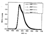
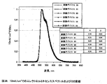
この図、および本明細書における以後の図において、窒素から金属(ここでは、Ir)への供与結合が直線として金属錯体中に描かれている。Ir(ppy)3は、CIE 0.3, 0.63でスペクトルを発し、500cd/m2の初期輝度で約10,000時間の半減期、および約6%の量子効率を有する。Kwong et al, Appl. Phys. Lett., 81, 162 (2002)。 In this figure, and in the subsequent figures herein, the donor bond from nitrogen to the metal (here Ir) is depicted as a straight line in the metal complex. Ir (ppy) 3 emits a spectrum at CIE 0.3, 0.63, has an initial brightness of 500 cd / m 2 and a half-life of about 10,000 hours, and a quantum efficiency of about 6%. Kwong et al, Appl. Phys. Lett., 81, 162 (2002).
工業規格は、フルカラーディスプレイの寿命が少なくとも約5000時間であることを要求している。さらに、高い安定性および効率は、高品質ディスプレイの重要な特性である。これらの要求に促されて、先行技術において達成されたものよりも、赤色、緑色および青色波長域において、より長い寿命、より高い安定性、より高い効率を示す燐光発光材料が求められるようになっている。本明細書において、向上したデバイス効率および安定性を有する燐光材料が開示される。 Industry standards require that the lifetime of a full color display be at least about 5000 hours. Furthermore, high stability and efficiency are important characteristics of high quality displays. Inspired by these requirements, phosphorescent materials have been sought that exhibit longer lifetime, higher stability, and higher efficiency in the red, green, and blue wavelength ranges than those achieved in the prior art. ing. Disclosed herein are phosphorescent materials with improved device efficiency and stability.
有機発光デバイスが提供される。 An organic light emitting device is provided.
前記デバイスは、アノード、カソード、およびアノードとカソードとの間に配置された発光層を有する。発光層はさらに以下の構造を有する発光材料を含む。 The device has an anode, a cathode, and a light emitting layer disposed between the anode and the cathode. The light emitting layer further includes a light emitting material having the following structure.
上記式中、
Mは、Ir、Pt、Rh、またはPdから選択される金属であり;
mは、1から、前記金属に結合し得る配位子の最大数までの値であり;
m+nは、前記金属に結合し得る配位子の最大数であり;
(X-Y)は、補助配位子であり;
環Aは、R'5の位置にアルキル置換基を有し、かつ前記金属Mに配位している少なくとも1個の窒素原子(N)を有する芳香族複素環または芳香族複素環式縮合環であり、前記環AはR'3、R'4、およびR'6の位置で1つまたは複数の置換基によって任意選択で置換されていてもよく;
加えて又は代わりに、環AのR'3およびR'4置換位置は、一緒に独立して、縮合環(任意選択で置換されていてもよい)を形成していてもよく;
環Bは、金属Mに配位している炭素原子を少なくとも1個有する芳香族環であり、環BはR3、R4、R5、およびR6の位置で1個または複数の置換基によって任意選択で置換されていてもよく;
R'3、R'4およびR'6は、それぞれ独立に、H、アルキル、アルケニル、アルキニル、ヘテロアルキル、アリール、ヘテロアリール、アラルキルであり;R'3、R'4およびR'6は1つまたは複数の置換基Zによって任意選択で置換されていてもよく;
R3、R4、R5、およびR6は、それぞれ独立に、H、アルキル、アルケニル、アルキニル、アルキルアリール、CN、CO2R、C(O)R、NR2、NO2、OR、ハロ、アリール、ヘテロアリール、置換アリール、置換ヘテロアリール、または複素環式基からなる群から選択されるが、
R'3、R'4、およびR'6が全てHである場合は、R3、R4、R5、およびR6もまた全てHであるか、
あるいは、R4、R5、およびR6の少なくとも1つが、前記金属に結合し得る最大数の配位子の2つ以上を共有結合で連結する連結基、非置換フェニル環、フルオロ置換フェニル環、
または、環Bに対して非置換フェニル環と同等もしくはそれより小さい程度でそのフェニル環を同一面上(coplanar)にする置換基で置換されているフェニル環であり;
あるいは、R'3およびR6は、-CR2-CR2-、-CR=CR-、-CR2-、-O-、-NR-、-O-CR2-、-NR-CR2-、および-N=CR-から選択される基によって架橋されていてもよく;
各Rは、独立に、H、アルキル、アルケニル、アルキニル、ヘテロアルキル、アリール、ヘテロアリール、またはアラルキルであり;Rは1つまたは複数の置換基Zによって任意選択で置換されていてもよく;
各Zは、独立に、ハロゲン、R'、OR'、N(R')2、SR'、C(O)R'、C(O)OR'、C(O)N(R')2、CN、SO2、SOR'、SO2R'、またはSO3R'であり;
各R'は、独立に、H、アルキル、アルケニル、アルキニル、ヘテロアルキル、アリール、またはヘテロアリールである。
In the above formula,
M is a metal selected from Ir, Pt, Rh, or Pd;
m is a value from 1 to the maximum number of ligands that can bind to the metal;
m + n is the maximum number of ligands that can bind to the metal;
(XY) is an auxiliary ligand;
Ring A is an aromatic heterocyclic ring or an aromatic heterocyclic condensed ring having an alkyl substituent at the position of R ′ 5 and having at least one nitrogen atom (N) coordinated to the metal M. Wherein said ring A may be optionally substituted with one or more substituents at the positions of R ′ 3 , R ′ 4 , and R ′ 6 ;
In addition or alternatively, the R ′ 3 and R ′ 4 substitution positions of ring A may independently form a fused ring (which may be optionally substituted);
Ring B is an aromatic ring having at least one carbon atom coordinated to metal M, and ring B is one or more substituents at positions R 3 , R 4 , R 5 , and R 6 Optionally substituted by
R ′ 3 , R ′ 4 and R ′ 6 are each independently H, alkyl, alkenyl, alkynyl, heteroalkyl, aryl, heteroaryl, aralkyl; R ′ 3 , R ′ 4 and R ′ 6 are 1 Optionally substituted by one or more substituents Z;
R 3 , R 4 , R 5 , and R 6 are each independently H, alkyl, alkenyl, alkynyl, alkylaryl, CN, CO 2 R, C (O) R, NR 2 , NO 2 , OR, halo Selected from the group consisting of, aryl, heteroaryl, substituted aryl, substituted heteroaryl, or heterocyclic group,
If R ′ 3 , R ′ 4 , and R ′ 6 are all H, then R 3 , R 4 , R 5 , and R 6 are also all H,
Alternatively, at least one of R 4 , R 5 , and R 6 is a linking group that covalently connects two or more of the maximum number of ligands that can be bonded to the metal, an unsubstituted phenyl ring, a fluoro-substituted phenyl ring ,
Or a phenyl ring that is substituted with a substituent that makes the phenyl ring coplanar to the same or less than the unsubstituted phenyl ring relative to ring B;
Alternatively, R '3 and R 6, -CR 2 -CR 2 -, - CR = CR -, - CR 2 -, - O -, - NR -, - O-CR 2 -, - NR-CR 2 - And may be cross-linked by a group selected from -N = CR-;
Each R is independently H, alkyl, alkenyl, alkynyl, heteroalkyl, aryl, heteroaryl, or aralkyl; R may be optionally substituted with one or more substituents Z;
Each Z is independently halogen, R ′, OR ′, N (R ′) 2 , SR ′, C (O) R ′, C (O) OR ′, C (O) N (R ′) 2 , CN, SO 2 , SOR ′, SO 2 R ′, or SO 3 R ′;
Each R ′ is independently H, alkyl, alkenyl, alkynyl, heteroalkyl, aryl, or heteroaryl.
発光材料自体もまた提供される。この発光材料は、発光デバイスに組み込まれたときに、向上した効率および安定性を有し得る。特に、本発明のデバイスは、公知のデバイスを凌ぐ、格段に向上した効率を示す。 The luminescent material itself is also provided. The luminescent material can have improved efficiency and stability when incorporated into a light emitting device. In particular, the device of the present invention exhibits a much improved efficiency over known devices.
別の態様において、発光層は以下の構造を有する発光材料を含む。 In another embodiment, the light emitting layer includes a light emitting material having the following structure.
上記式中、
Mは、Ir、Pt、Rh、またはPdから選択される金属であり;
(X-Y)は、補助配位子であり;
mは、1から、前記金属に結合し得る配位子の最大数までの値であり;
m+nは、前記金属に結合し得る配位子の最大数であり;
環Aは、前記金属Mに配位している少なくとも1個の窒素原子(N)を有する芳香族複素環または芳香族複素環式縮合環であり、前記環AはR'3、R'4、R'5、およびR'6の位置で1つまたは複数の置換基によって任意選択で置換されていてもよく;
加えて又は代わりに、環AのR'3およびR'4置換位置は、一緒に独立して、縮合環(任意選択で置換されていてもよい)を形成していてもよく;
環Bは、金属Mに配位している炭素原子を少なくとも1個有する芳香族環であり、環Bは、R3、R4、R5、およびR6の位置で1個または複数の置換基によって任意選択で置換されていてもよく;
R'3、R'4、R'5およびR'6は、それぞれ独立に、H、アルキル、アルケニル、アルキニル、ヘテロアルキル、アリール、ヘテロアリール、アラルキルであり;R'3、R'4、およびR'6は1つまたは複数の置換基Zによって任意選択で置換されていてもよく;
R3、R4、R5、およびR6は、それぞれ独立に、H、アルキル、アルケニル、アルキニル、アルキルアリール、CN、CO2R、C(O)R、NR2、NO2、OR、ハロ、アリール、ヘテロアリール、置換アリール、置換ヘテロアリール、または複素環式基からなる群から選択され、
あるいは、R'3およびR6は、-CR2-CR2-、-CR=CR-、-CR2-、-O-、-NR-、-O-CR2-、-NR-CR2-、および-N=CR-から選択される基によって架橋されていてもよく;
各Rは、独立に、H、アルキル、アルケニル、アルキニル、ヘテロアルキル、アリール、ヘテロアリール、またはアラルキルであり;Rは1つまたは複数の置換基Zによって任意選択で置換されていてもよく;
各Zは、独立に、ハロゲン、R'、OR'、N(R')2、SR'、C(O)R'、C(O)OR'、C(O)N(R')2、CN、SO2、SOR'、SO2R'、またはSO3R'であり;
各R'は、独立に、H、アルキル、アルケニル、アルキニル、ヘテロアルキル、アリール、またはヘテロアリールであり、
R3、R4、R5、R6、R'3、R'4、R'5、およびR'6の少なくとも1つは、アルキルもしくはアリール置換基である。
In the above formula,
M is a metal selected from Ir, Pt, Rh, or Pd;
(XY) is an auxiliary ligand;
m is a value from 1 to the maximum number of ligands that can bind to the metal;
m + n is the maximum number of ligands that can bind to the metal;
Ring A is an aromatic heterocyclic ring or an aromatic heterocyclic condensed ring having at least one nitrogen atom (N) coordinated to the metal M, and the ring A is R ′ 3 , R ′ 4 , R ′ 5 , and R ′ 6 may be optionally substituted with one or more substituents;
In addition or alternatively, the R ′ 3 and R ′ 4 substitution positions of ring A may independently form a fused ring (which may be optionally substituted);
Ring B is an aromatic ring having at least one carbon atom coordinated to metal M, and ring B is one or more substituted at the positions R 3 , R 4 , R 5 , and R 6 Optionally substituted by a group;
R ′ 3 , R ′ 4 , R ′ 5 and R ′ 6 are each independently H, alkyl, alkenyl, alkynyl, heteroalkyl, aryl, heteroaryl, aralkyl; R ′ 3 , R ′ 4 , and R ′ 6 may be optionally substituted with one or more substituents Z;
R 3 , R 4 , R 5 , and R 6 are each independently H, alkyl, alkenyl, alkynyl, alkylaryl, CN, CO 2 R, C (O) R, NR 2 , NO 2 , OR, halo Selected from the group consisting of, aryl, heteroaryl, substituted aryl, substituted heteroaryl, or heterocyclic groups;
Alternatively, R '3 and R 6, -CR 2 -CR 2 -, - CR = CR -, - CR 2 -, - O -, - NR -, - O-CR 2 -, - NR-CR 2 - And may be cross-linked by a group selected from -N = CR-;
Each R is independently H, alkyl, alkenyl, alkynyl, heteroalkyl, aryl, heteroaryl, or aralkyl; R may be optionally substituted with one or more substituents Z;
Each Z is independently halogen, R ′, OR ′, N (R ′) 2 , SR ′, C (O) R ′, C (O) OR ′, C (O) N (R ′) 2 , CN, SO 2 , SOR ′, SO 2 R ′, or SO 3 R ′;
Each R ′ is independently H, alkyl, alkenyl, alkynyl, heteroalkyl, aryl, or heteroaryl;
At least one of R 3 , R 4 , R 5 , R 6 , R ′ 3 , R ′ 4 , R ′ 5 , and R ′ 6 is an alkyl or aryl substituent.
この態様における発光材料もまた提供される。この発光材料は発光デバイスに組み込まれたときに、向上した効率および安定性を有し得る。 A luminescent material in this aspect is also provided. The luminescent material can have improved efficiency and stability when incorporated into a light emitting device.
好ましい態様において、発光材料はトリス化合物(この場合、m=3)である。 In a preferred embodiment, the luminescent material is a tris compound (in this case, m = 3).
〔詳細な説明〕
一般に、OLEDはアノードとカソードの間に配置され、これらに電気的に接続された少なくとも1つの有機層を備える。電流を流すと、(1つ又は複数の)有機層に、アノードは正孔を注入し、カソードは電子を注入する。注入された正孔と電子はそれぞれ、反対に帯電電した電極に向かって移動する。電子と正孔が同じ分子に局在する時、「励起子」(励起エネルギー状態を有する局在化した電子-正孔対である)が生成される。励起子が光放出機構により緩和するときに光が放出される。いくつかの場合には、励起子はエキシマーまたはエキシプレックスに局在化されることがある。非放射機構、例えば熱緩和もまた起こり得るが、通常、望ましくないと考えられている。
[Detailed explanation]
In general, an OLED comprises at least one organic layer disposed between and electrically connected to an anode and a cathode. When current is passed, the anode injects holes and the cathode injects electrons into the organic layer (s). The injected holes and electrons each move toward the charged electrode. When an electron and hole are localized in the same molecule, an “exciton” (a localized electron-hole pair with an excited energy state) is generated. Light is emitted when excitons are relaxed by the light emission mechanism. In some cases, excitons may be localized to excimers or exciplexes. Non-radiative mechanisms, such as thermal relaxation, can also occur but are generally considered undesirable.
初期のOLEDでは、例えば、米国特許第4769292号(参照により全体を援用する)に開示されているように、一重項状態から発光する(「蛍光」)発光分子を用いた。蛍光発光は一般に、10ナノ秒未満の時間範囲に起こる。 Early OLEDs used luminescent molecules that emitted light from a singlet state (“fluorescence”), as disclosed, for example, in US Pat. No. 4,476,922, which is incorporated by reference in its entirety. Fluorescence emission generally occurs in a time range of less than 10 nanoseconds.
より最近、三重項状態から発光する(「燐光」)発光材料を有するOLEDが実際に示された。Baldo et al., "Highly Efficient Phosphorescent Emission from Organic Electroluminescent Devices", Nature, vol. 395, 151-154, 1998(「Baldo-I」)、および、Baldo et al., "Very high-efficiency green organic light-emitting devices based on electrophosphorescence", Appl. Phys. Lett., vol. 75, No. 3, 4-6 (1999)(「Baldo-II」)(これらは参照により全体を援用する)。燐光は、遷移がスピン状態の変化を必要とするので「禁制」遷移といわれることがあり、量子力学はこのような遷移は好ましくないことを示している。結果として、燐光は、一般に、少なくとも10ナノ秒を超える時間範囲で起こり、典型的には100ナノ秒を超える。燐光の自然な放射寿命が余りに長いと、三重項が非放射機構により減衰して全く光が放出されないということがあり得る。有機燐光は、しばしば、非共有電子対を有するヘテロ原子を含む分子においてもまた、非常に低温で観察される。2,2'-ビピリジンはこのような分子である。非放射減衰機構は通常、温度に依存するので、液体窒素の温度で燐光を示す材料でも、室温では燐光を示さないであろう。しかし、Baldoにより実証されたように、室温で実際に燐光を発する燐光化合物を選択することによって、この問題に取り組むことができる。代表的な発光層には、ドープまたは無ドープ燐光有機-金属材料が含まれ、以下に開示されている:米国特許第6303238号、米国特許第6310360号;米国特許出願公開第2002-0034656号、米国特許出願公開第2002-0182441号;および米国特許出願公開第2003-0072964号;ならびに国際公開WO-02/074015。 More recently, OLEDs having emissive materials that emit light from triplet states (“phosphorescence”) have been shown in practice. Baldo et al., "Highly Efficient Phosphorescent Emission from Organic Electroluminescent Devices", Nature, vol. 395, 151-154, 1998 ("Baldo-I") and Baldo et al., "Very high-efficiency green organic light -emitting devices based on electrophosphorescence ", Appl. Phys. Lett., vol. 75, No. 3, 4-6 (1999) (" Baldo-II ") (these are incorporated by reference in their entirety). Phosphorescence is sometimes referred to as a “forbidden” transition because the transition requires a change in the spin state, and quantum mechanics indicates that such a transition is undesirable. As a result, phosphorescence generally occurs in a time range that exceeds at least 10 nanoseconds, and typically exceeds 100 nanoseconds. If the natural emission lifetime of phosphorescence is too long, it is possible that the triplet is attenuated by a non-radiative mechanism and no light is emitted. Organic phosphorescence is often observed at very low temperatures also in molecules containing heteroatoms with unshared electron pairs. 2,2'-bipyridine is such a molecule. Since non-radiative decay mechanisms are usually temperature dependent, materials that exhibit phosphorescence at the temperature of liquid nitrogen will not exhibit phosphorescence at room temperature. However, as demonstrated by Baldo, this problem can be addressed by selecting phosphorescent compounds that actually phosphorescence at room temperature. Exemplary light emitting layers include doped or undoped phosphorescent organo-metallic materials and are disclosed below: US Pat. No. 6,303,238, US Pat. No. 6,310,360; US Patent Application Publication No. 2002-0034656, US Patent Application Publication No. 2002-0182441; and US Patent Application Publication No. 2003-0072964; and International Publication WO-02 / 074015.
一般に、OLED中の励起子は、約3:1の比で、すなわち、約75%の三重項と約25%の一重項として、生成されると考えられている。Adachi et al., "Nearly 100% Internal Phosphorescent Efficiency In An Organic Light Emitting Device", J. Appl. Phys., 90, 5048 (2001)(参照により全体を援用する)を参照されたい。多くの場合、一重項励起子は「項間交差」を通じて三重項励起状態に容易にエネルギーを移動できるが、三重項励起子はエネルギーを一重項励起状態に容易には移動できない。結果として、燐光OLEDにより、理論的に100%の内部量子効率が可能である。蛍光デバイスにおいて、三重項励起子のエネルギーは通常、デバイスを昇温させる無放射減衰過程に費やされるので、結果的に内部量子効率はずっと小さくなる。三重項励起状態から発光する燐光材料を用いるOLEDが、例えば、米国特許第6303238号(参照により全体を援用する)に開示されている。 In general, excitons in OLEDs are believed to be generated in a ratio of about 3: 1, ie, about 75% triplets and about 25% singlets. See Adachi et al., “Nearly 100% Internal Phosphorescent Efficiency In An Organic Light Emitting Device”, J. Appl. Phys., 90, 5048 (2001) (incorporated by reference in its entirety). In many cases, singlet excitons can easily transfer energy to the triplet excited state through “intersystem crossing”, but triplet excitons cannot easily transfer energy to the singlet excited state. As a result, 100% internal quantum efficiency is theoretically possible with phosphorescent OLEDs. In fluorescent devices, triplet exciton energy is usually spent in a radiationless decay process that raises the temperature of the device, resulting in much lower internal quantum efficiency. OLEDs using phosphorescent materials that emit light from triplet excited states are disclosed, for example, in US Pat. No. 6,303,238 (incorporated by reference in its entirety).
燐光発光に先立って、三重項励起状態から、発光減衰が起こる中間の非三重項状態への遷移が起こる。例えば、ランタニド元素に配位した有機分子は、しばしば、ランタニド金属に局在化した励起状態から燐光を発する。しかし、このような材料は三重項状態から直接、燐光を発するのでなく、代わりに、ランタニド金属イオンに集中した原子励起状態から発光する。ユウロピウムジケトナート錯体はこれらのタイプの化学種の1群を例示する。 Prior to phosphorescence emission, a transition from a triplet excited state to an intermediate non-triplet state where emission decay occurs. For example, organic molecules coordinated to a lanthanide element often emit phosphorescence from an excited state localized to the lanthanide metal. However, such materials do not emit phosphorescence directly from the triplet state, but instead emit from an atomic excited state concentrated in the lanthanide metal ion. Europium diketonate complexes illustrate one group of these types of species.
三重項からの燐光は、有機分子を大きな原子番号の原子のごく近くに、好ましくは結合を通じて留めることによって蛍光を超えて増大させることができる。この現象は、重原子効果と呼ばれ、スピン-軌道カップリングとして知られている機構によって生じる。このような燐光遷移は、トリス(2-フェニルピリジン)イリジウム(III)のような有機金属分子の励起金属から配位子への電荷移動(metal-to-ligand charge transfer、MLCT)状態により観察される。 Phosphorescence from the triplet can be increased beyond fluorescence by keeping the organic molecule in close proximity to the high atomic number atom, preferably through a bond. This phenomenon is called the heavy atom effect and is caused by a mechanism known as spin-orbit coupling. Such phosphorescent transitions are observed by the metal-to-ligand charge transfer (MLCT) state of excited metal to ligand of organometallic molecules such as tris (2-phenylpyridine) iridium (III). The
本明細書では、「三重項エネルギー」という用語は、与えられた材料の燐光スペクトル中に認められる最も高いエネルギーピークに対応するエネルギーを表す。最も高いエネルギーピークは、必ずしも、燐光スペクトルにおける最大強度を有するピークではなく、例えば、このようなピークの高エネルギー側の明瞭な肩の局所的最大値であり得る。 As used herein, the term “triplet energy” refers to the energy corresponding to the highest energy peak found in the phosphorescence spectrum of a given material. The highest energy peak is not necessarily the peak with the highest intensity in the phosphorescence spectrum, but can be, for example, the local maximum of a distinct shoulder on the high energy side of such a peak.
本明細書では、「有機金属」という用語は当業者に一般に理解されている通りであり、例えば、"Inorganic Chemistry" (2nd Edition), Gary L. Miessler and Donald A. Tan, Pentice-Hall (1998)、に記載されている通りである。したがって、有機金属という用語は、炭素-金属の結合を通じて金属に結合した有機基を有する化合物を表す。有機金属それ自体には配位化合物は含まれておらず、配位化合物はヘテロ原子からの供与結合(donor bond)だけを有する物質(例えば、アミン、ハライド、擬ハライド(CNなど)の金属錯体)である。実際に、有機金属化合物は、有機化学種への炭素-金属結合の1つまたは複数以外に、ヘテロ原子からの供与結合の1つまたは複数を通常含む。有機化学種への炭素-金属結合は、金属と有機基(例えば、フェニル、アルキル、アルキニルなど)の炭素原子との間の直接結合をいうが、CNの炭素のような「無機炭素」への金属結合をいわない。 As used herein, the term “organometallic” is as commonly understood by those skilled in the art, for example, “Inorganic Chemistry” (2nd Edition), Gary L. Miessler and Donald A. Tan, Pentice-Hall (1998). ). Thus, the term organometallic refers to a compound having an organic group bonded to a metal through a carbon-metal bond. Organometallics themselves do not contain coordination compounds, which are metal complexes of substances having only donor bonds from heteroatoms (e.g. amines, halides, pseudohalides (CN, etc.)). ). In fact, organometallic compounds usually contain one or more of the donor bonds from the heteroatom, in addition to one or more of the carbon-metal bonds to the organic species. A carbon-metal bond to an organic species refers to a direct bond between a metal and a carbon atom of an organic group (e.g., phenyl, alkyl, alkynyl, etc.), but to an “inorganic carbon” such as the carbon of CN. Does not require metal bonding.
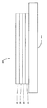
図1は有機発光デバイス100を示している。この図は、必ずしも一定の縮尺で描かれていない。デバイス100は、基材110、アノード115、正孔注入層120、正孔輸送層125、電子阻止層130、発光層135、正孔阻止層140、電子輸送層(ETL)145、電子注入層150、保護層155、およびカソード160を含み得る。カソード160は、第1導電層162および第2導電層164を有する複合カソードである。デバイス100は、記載した層を順次、堆積させることによって製造できる。
FIG. 1 shows an organic
基材110は望みの構造特性をもたせる任意の適切な基材であってもよい。基材110は柔軟であっても堅くてもよい。基材110は透明、半透明または不透明であり得る。プラスチックおよびガラスは好ましい堅い基材材料の例である。プラスチックおよび金属箔は好ましい柔軟基材材料の例である。基材110は回路の作製を容易にするために、半導体材料であってもよい。例えば、基材110は、続いて基材上に堆積されるOLEDを制御できる回路がその上に作製されているシリコンウェハであってもよい。他の基材を使用してもよい。基材110の材料および厚さは、望みの構造および光学特性が得られるように選択され得る。
アノード115は、有機層に正孔を輸送するのに十分導電性である任意の適切なアノードであってもよい。アノード115の材料は、約4eVより大きい仕事関数を有する(「高仕事関数材料」)。好ましいアノード材料には、導電性金属酸化物、例えば、インジウムスズ酸化物(ITO)およびインジウム亜鉛酸化物(IZO)、アルミニウム亜鉛酸化物(AlZnO)、および金属が含まれる。アノード115(および基材110)は、下部発光デバイスを作り出すのに十分なだけ透明であり得る。好ましい透明基材とアノードの組合せは、ガラスまたはプラスチック(基材)上に堆積された市販のITO(アノード)である。柔軟で透明な基材-アノードの組合せは、米国特許第5844363号および米国特許第6602540号B2(これらは参照により全体を援用する)に開示されている。アノード115は不透明および/または反射性であり得る。反射性アノード115は、デバイスの上部からの発光量を増加させるために、いくつかの上部発光デバイスのとって好ましいものであり得る。アノード115の材料および厚さは、望みの導電性および光学特性が得られるように選択され得る。アノード115が透明である場合は、特定の材料に対して、望みの導電性をもたせるのに十分なだけ厚いが、それでも望みの透明度をもたせるのに十分なだけ薄い、厚さの範囲があり得る。他のアノード材料および構造を用いてもよい。
The
正孔輸送層125には、正孔を輸送できる材料が含まれ得る。正孔輸送層130は真性(ドープされていない)であってもドープされていてもよい。ドーピングは導電性を増すために使用され得る。α-NPDおよびTPDは真性正孔輸送層の例である。p型ドープ正孔輸送層の例は、Forrestらの米国特許出願公開第2002-0071963号(参照により全体を援用する)に開示されているように、50:1のモル比でF4-TCNQによりドープされたm-MTDATAである。他の正孔輸送層を用いてもよい。
The
発光層135は、電流がアノード115とカソード160との間に流れたときに発光できる有機材料を含み得る。好ましくは、発光層135は燐光発光材料を含むが、蛍光発光材料もまた使用され得る。燐光材料が、このような材料に付随する高いルミネセンス効率のために好ましい。発光層135はまた、電子および/または正孔を輸送できるホスト材料(電子、正孔、および/または励起子を捕捉し得る発光材料によりドープされている)を含んでいてもよく、励起子は光放出機構により発光材料から緩和する。発光層135は、輸送および発光特性を併せもつ単一材料を含んでいてもよい。発光材料がドーパントであるか主成分であるかに関わらず、発光層135は、発光材料の発光波長を調整するドーパントのような他の材料を含み得る。発光層135は、組み合わされて、望みの光スペクトルを発光できる複数の発光材料を含んでいてもよい。燐光発光材料の例には、Ir(ppy)3が含まれる。蛍光発光材料の例には、DCMおよびDMQAが含まれる。ホスト材料の例には、Alq3、CBP、およびmCPが含まれる。発光性でホストである材料の例は、Thompsonらの米国特許第6303238号(参照により全体を援用する)に開示されている。発光材料は発光層135に多くのやり方で含まれ得る。例えば、発光性の小分子がポリマーに組み込まれていてもよい。これは、いくつかのやり方によって、例えば、小分子を、別個の独立した分子種としてポリマーにドープすることによって;あるいは、コポリマーを生成するように小分子をポリマー骨格に組み入れることによって;あるいは、小分子をポリマーにペンダント基として結合させることによって実施できる。他の発光層材料および構造を用いてもよい。例えば、小分子の発光材料はデンドリマーのコアとして存在してもよい。
The light-emitting
多くの有用な発光材料は、金属中心に結合した1種または複数の配位子を含む。配位子は、それが有機金属発光材料の光活性に直接寄与する場合、「光活性」とよぶことができる。「光活性」配位子は、金属と共同で、光子が放出されるときに、電子がそこから、またそこへ移動する複数のエネルギー準位を提供する。他の配位子は「補助」とよぶことができる。補助配位子は、例えば、光活性配位子のエネルギー準位をシフトさせることによって、分子の光活性を変化させ得るが、補助配位子は光の放出に関与するエネルギー準位を直接提供しない。1つの分子において光活性である配位子は別の分子においては補助である得る。光活性および補助のこれらの定義は非限定的な理論を意図したものである。 Many useful luminescent materials include one or more ligands bonded to a metal center. A ligand can be referred to as “photoactivity” if it directly contributes to the photoactivity of the organometallic luminescent material. “Photoactive” ligands, in conjunction with metals, provide multiple energy levels from which electrons move to and from when photons are emitted. Other ligands can be referred to as “auxiliary”. Auxiliary ligands can change the photoactivity of the molecule, for example, by shifting the energy level of the photoactive ligand, while the auxiliary ligand directly provides the energy level involved in the emission of light. do not do. A ligand that is photoactive in one molecule may be ancillary in another molecule. These definitions of photoactivity and auxiliary are intended for non-limiting theory.
電子輸送層(ETL)140は、電子を輸送できる材料を含み得る。電子輸送層140は、真性(ドープされていない)であることも、またはドープされていることもある。ドーピングは導電性を増すために使用され得る。Alq3は真性電子輸送層の例である。n型ドープ電子輸送層の例は、Forrestらの米国特許出願公開第2002-0071963号(参照により全体を援用する)に開示されているように、1:1のモル比でLiによりドープされたBPhenである。他の電子輸送層を用いてもよい。
The electron transport layer (ETL) 140 may include a material that can transport electrons. The
電子輸送層の電荷担体成分は、電子がカソードから電子輸送層のLUMO(最低空分子軌道)へ効率的に注入され得るように選択され得る。「電荷担体成分」は、実際に電子を輸送するLUMOを担う材料である。この成分は基礎(ベース)材料であるか、あるいはそれはドーパントであってもよい。有機材料のLUMO準位は一般にその材料の電子親和力により特徴付けることができ、カソードの相対的電子注入効率は一般にカソード材料の仕事関数によって特徴付けることができる。これは、電子輸送層と近くのカソードの好ましい性質は、ETLの電荷担体成分の電子親和力とカソード材料の仕事関数とによって特定できることを意味する。特に、高い電子注入効率を実現するために、カソード材料の仕事関数は、電子輸送層の電荷担体成分の電子親和力より、好ましくは約0.75eV以下であり、より好ましくは約0.5eV以下である。同様の考慮は電子が注入される如何なる層にも適用される。 The charge carrier component of the electron transport layer can be selected so that electrons can be efficiently injected from the cathode into the LUMO (lowest empty molecular orbital) of the electron transport layer. The “charge carrier component” is the material responsible for LUMO that actually transports electrons. This component may be a base material or it may be a dopant. The LUMO level of an organic material can generally be characterized by the electron affinity of the material, and the relative electron injection efficiency of the cathode can generally be characterized by the work function of the cathode material. This means that the favorable properties of the electron transport layer and the nearby cathode can be specified by the electron affinity of the charge carrier component of the ETL and the work function of the cathode material. In particular, in order to achieve high electron injection efficiency, the work function of the cathode material is preferably about 0.75 eV or less, more preferably about 0.5 eV or less than the electron affinity of the charge carrier component of the electron transport layer. Similar considerations apply to any layer into which electrons are injected.
カソード160は、当技術分野で公知の、カソード160が電子を伝導しデバイス100の有機層に注入できるような、任意の適切な材料または材料の組合せであってもよい。カソード160は透明または不透明であり、また反射性であり得る。金属および金属酸化物は適切なカソード材料の例である。カソード160は単層であるか、あるいは複合構造を有していてもよい。図1は、薄い金属層162とより厚い導電性金属酸化物層164とを有する複合カソード160を示している。複合カソードにおいて、より厚い層164の好ましい材料には、ITO、IZO、および当技術分野で公知のその他の材料が含まれる。米国特許第5703436号、米国特許第5707745号、米国特許第6548956号B2、および米国特許第6576134号B2(これらは参照により全体を援用する)は、スパッタリングにより堆積させた透明で導電性のITO層が上に重なったMg:Agのような薄い金属層を有する複合カソードを含めて、カソードの例を開示している。下にある有機層と接触しているカソード160の部分は、それが単層カソード160、複合カソードの薄い金属層162、または何らかの他の部分であるかどうかに関わらず、好ましくは、約4eVより小さい仕事関数を有する材料(「低仕事関数材料」)からなる。他のカソード材料および構造を用いてもよい。
阻止層(ブロッキング層)は、発光層から出て行く電荷担体(電子または正孔)および/または励起子の数を減らすために使用され得る。電子阻止層130は、電子が発光層135を出て正孔輸送層125に向かうことを防ぐために、発光層135と正孔輸送層125との間に配置され得る。同様に、正孔阻止層140は、正孔が発光層135を出て電子輸送層140に向かうことを防ぐために、発光層135と電子輸送層145との間に配置され得る。ブロック層はまた、励起子が発光層から拡散して出て行くのを防ぐためにも使用され得る。ブロック層の理論と使用は、より詳細に、米国特許第6097147号およびForrestらの米国特許出願公開第2002-0071963号(これらは参照により全体を援用する)に記載されている。
The blocking layer (blocking layer) can be used to reduce the number of charge carriers (electrons or holes) and / or excitons that leave the light emitting layer. The
本明細書では、「阻止層」という用語は、この層がデバイスを通しての電荷担体および/または励起子の輸送を著しく抑制するバリアを提供することを意味するが、この層が電荷担体および/または励起子を必ずしも完全にブロックすることは含んでいない。デバイスにこのような阻止層が存在することにより、阻止層のない類似のデバイスに比べて効率は相当に高くなり得る。また、阻止層は、OLEDの望ましい部分に発光を限定するためにも使用され得る。 As used herein, the term “blocking layer” means that the layer provides a barrier that significantly inhibits the transport of charge carriers and / or excitons through the device, but the layer is charge carriers and / or It does not include completely blocking excitons. The presence of such a blocking layer in the device can be much more efficient than a similar device without the blocking layer. The blocking layer can also be used to limit light emission to the desired portion of the OLED.
一般に、注入層は、1つの層、例えば電極または有機層から、近くの有機層への電荷担体の注入を促進し得る材料からなる。注入層はまた電荷輸送機能もまた果たし得る。デバイス100において、正孔注入層120は、アノード115から正孔輸送層125への正孔の注入を促進する如何なる層であってもよい。CuPcはITOアノード115、およびその他のアノードからの正孔注入層として使用され得る材料の例である。デバイス100において、電子注入層150は、電子輸送層145への電子の注入を促進する如何なる層であってもよい。LiF/Alは隣の層から電子輸送層への電子注入層として使用され得る材料の例である。他の材料または材料の組合せを注入層に用いてもよい。特定のデバイス構成に応じて、注入層はデバイス100において示されているものとは異なる位置に配置されてもよい。注入層のさらなる例は、Luらの米国特許出願第09/931948号(参照により全体を援用する)に記載されている。正孔注入層は、スピンコートされたポリマー(例えばPEDOT:PSS)のように、溶液から堆積された材料を含んでいるか、あるいは、それは気相堆積された小分子材料(例えば、CuPcまたはMTDATA)でもあり得る。
In general, an injection layer is made of a material that can facilitate the injection of charge carriers from one layer, such as an electrode or organic layer, into a nearby organic layer. The injection layer can also perform a charge transport function. In the
正孔注入層(HIL)は、アノードから正孔注入材料への正孔の注入を効率的にするために、アノード表面を平坦化するか、または濡らしてもよい。正孔注入層はまた、HILの一方の側に隣接するアノード層とHILの反対側の正孔輸送層とに、都合よく適合するHOMO(最高被占分子軌道)エネルギー準位(本明細書に記載されている相対イオン化ポテンシャル(IP)エネルギーにより定まる)を有する電荷担体成分も含み得る。「電荷担体成分」は、実際に正孔を輸送するHOMOを担う材料である。この成分はHILのベース材料あるか、あるいは、それはドーパントであってもよい。ドープされたHILを用いることにより、ドーパントをその電気的性質で選択でき、ホストをモルホロジー的性質(例えば、濡れ性、柔軟性、靱性など)で選択できる。HIL材料の好ましい性質は、正孔をアノードからHIL材料に効率的に注入できるということである。特に、HILの電荷担体成分は、好ましくは、アノード材料のIPより約0.7eVを超えて大きくはないIPを有する。より好ましくは、電荷担体成分は、アノード材料より約0.5eVを超えて大きくはないIPを有する。同様の考慮は正孔が注入される如何なる層にも適用される。このようなHIL材料が一般的な正孔輸送材料の正孔伝導度より相当に小さい正孔伝導度を有し得るという点において、HIL材料はOLEDの正孔輸送層に通常使用される一般的な正孔輸送材料からさらに区別される。本発明でのHILの厚さは、アノード層の表面を平坦化するか、または濡らすのに十分なだけの厚さであり得る。例えば、10nmのように小さいHILの厚さでも、非常に滑らかなアノード表面では許容され得る。しかし、アノード表面は非常に粗い傾向があるので、いくつかの場合には50nmまでのHILの厚さが望まれる。 A hole injection layer (HIL) may planarize or wet the anode surface in order to efficiently inject holes from the anode into the hole injection material. The hole injection layer also has a HOMO (Highest Occupied Molecular Orbital) energy level (referred to herein) that is conveniently matched to the anode layer adjacent to one side of the HIL and the hole transport layer opposite the HIL. A charge carrier component having a relative ionization potential (IP) energy as described) may also be included. The “charge carrier component” is a material responsible for HOMO that actually transports holes. This component may be a HIL base material or it may be a dopant. By using doped HIL, the dopant can be selected by its electrical properties and the host can be selected by morphological properties (eg, wettability, flexibility, toughness, etc.). A preferred property of the HIL material is that holes can be efficiently injected from the anode into the HIL material. In particular, the charge carrier component of the HIL preferably has an IP that is not greater than about 0.7 eV above the IP of the anode material. More preferably, the charge carrier component has an IP that is not greater than about 0.5 eV greater than the anode material. Similar considerations apply to any layer into which holes are injected. HIL materials are commonly used in OLED hole transport layers in that such HIL materials can have a hole conductivity substantially less than that of common hole transport materials. A further distinction from positive hole transport materials. The thickness of the HIL in the present invention may be sufficient to flatten or wet the surface of the anode layer. For example, even a HIL thickness as small as 10 nm can be tolerated on a very smooth anode surface. However, since the anode surface tends to be very rough, in some cases a HIL thickness of up to 50 nm is desired.
保護層は次の製造工程の間、下にある層を保護するために使用され得る。例えば、金属または金属酸化物の上部電極を作製するために用いられる工程は有機層を損傷し得るので、保護層はこのような損傷を減らすかまたは無くすために使用され得る。デバイス100において、保護層155は、カソード160の作製中、下にある有機層への損傷を減らすことができる。好ましくは、保護層は、それがデバイス100の駆動電圧を著しく増加させないように、それが輸送する担体のタイプ(デバイス100では電子)に対する大きな担体移動度を有する。CuPc、BCP、および様々な金属フタロシアニンは、保護層に使用され得る材料の例である。他の材料または材料の組合せを用いてもよい。好ましくは、保護層155の厚さは、有機保護層160が堆積された後に実施される製造工程によって下にある層への損傷がほとんどまたは全くないのに十分なだけ厚いが、デバイス100の駆動電圧を著しく増加させる程には厚くない。保護層155はその導電性を増すためにドープされてもよい。例えば、CuPCまたはBCPの保護層160はLiによりドープされ得る。保護層のより詳細な説明は、Luらの米国特許出願第09/931948号(参照により全体を援用する)に見出すことができる。
The protective layer can be used to protect the underlying layer during the next manufacturing process. For example, since the process used to make the metal or metal oxide top electrode can damage the organic layer, the protective layer can be used to reduce or eliminate such damage. In the
図2は上下逆(反転型)のOLED200を示している。このデバイスは、基材210、カソード215、発光層220、正孔輸送層225、およびアノード230を含む。デバイス200は記載した層を順次、堆積させることによって製造できる。最も普通のOLEDの構成はアノードの上方に配置されたカソードを有し、デバイス200はアノード230の下方に配置されたカソード215を有するので、デバイス200を「上下逆の」OLEDということができる。デバイス100に関して記載したものに類似の材料を、デバイス200の対応する層に使用できる。図2は、デバイス100の構造から如何にいくつかの層を省けるかの1つの例を提供している。
FIG. 2 shows an upside down (inverted)
図1および2に図示されている簡単な層状構造は非限定的な例として提供しており、本発明の実施形態は多様なその他の構造に関連して使用され得ることが分かる。記載されている具体的な材料および構造は事実上例示であり、他の材料および構造も使用できる。設計、性能、およびコスト要因に基づいて、様々なやり方で、記載された様々な層を結び付けて一体化することによって、作動し得るOLEDを実現しても、あるいは、いくつかの層を完全に省いてもよい。具体的に記載されていない他の層もまた含まれ得る。具体的に記載されているもの以外の材料を用いてもよい。本明細書に記載されている例の多くは単一の材料を含むものとして様々な層を記載しているが、材料の組合せ(例えばホストおよびドーパントの混合物、またはより一般的に混合物)を用いてもよい。また、層は様々な付属層(sublayer)を有し得る。本明細書において様々な層に与えられている名称は、厳格に限定しようとするものではない。例えば、デバイス200において、正孔輸送層225は正孔を輸送し、発光層220に正孔を注入するので、正孔輸送層として、あるいは正孔注入層としても記載され得る。一実施形態において、OLEDは、カソードとアノードとの間に配置された「有機層」を有するとして記載され得る。この有機層は単一の層を含むか、あるいは、例えば図1および2に関連して記載された様々な有機材料の複数の層をさらに含んでいてもよい。
It will be appreciated that the simple layered structure illustrated in FIGS. 1 and 2 is provided as a non-limiting example, and embodiments of the present invention can be used in connection with a variety of other structures. The specific materials and structures described are illustrative in nature and other materials and structures can be used. Based on design, performance, and cost factors, you can achieve an operational OLED by combining and integrating the various layers described in different ways, or even several layers completely May be omitted. Other layers not specifically described may also be included. Materials other than those specifically described may be used. Many of the examples described herein describe various layers as containing a single material, but use a combination of materials (e.g., a mixture of host and dopant, or more generally a mixture). May be. The layer can also have various sublayers. The names given to the various layers herein are not intended to be strictly limiting. For example, in the
Friendらの米国特許第5247190号(参照により全体を援用する)に開示されているようなポリマー材料で構成されるOLED(PLED)のように、具体的に記載されていない構造および材料もまた使用してよい。さらなる例として、単一の有機層を有するOLEDが使用され得る。OLEDは、例えば、Forrestらの米国特許第5707745号(参照により全体を援用する)に記載されているようにして積層できる。OLEDの構造は、図1および2に示されている簡単な層状構造から逸脱していてもよい。例えば、基材は、光取出し(out-coupling)を向上させるために、Forrestらの米国特許第6091195号(参照により全体を援用する)に記載されているメサ構造、および/または、Bulovicらの米国特許第5834893号(参照により全体を援用する)に記載されているピット構造のような、角度の付いた反射表面を含み得る。 Structures and materials not specifically described may also be used, such as OLEDs (PLEDs) composed of polymeric materials as disclosed in Friend et al. US Pat. No. 5,247,190 (incorporated by reference in their entirety). You can do it. As a further example, an OLED having a single organic layer may be used. OLEDs can be laminated, for example, as described in Forrest et al. US Pat. No. 5,777,745 (incorporated by reference in its entirety). The structure of the OLED may deviate from the simple layered structure shown in FIGS. For example, the substrate may be a mesa structure as described in Forrest et al., US Pat. No. 6,911,195 (incorporated in its entirety by reference) and / or Bulovic et al. To improve out-coupling. It may include an angled reflective surface, such as the pit structure described in US Pat. No. 5,834,893 (incorporated by reference in its entirety).
特に断らなければ、様々な実施形態の層のいずれも、何らかの適切な方法によって堆積され得る。有機層では、好ましい方法には、熱蒸着(thermal evaporation)、インクジェット(例えば、米国特許第6013982号および米国特許第6087196号(これらは参照により全体を援用する)記載されている)、有機気相成長(organic vapor phase deposition、OVPD)(例えば、Forrestらの米国特許第6337102号(参照により全体を援用する)に記載されている)、ならびに、有機気相ジェットプリンティング(organic vapor jet printing、OVJP)(例えば、米国特許出願第10/233470号(参照により全体を援用する)に記載されている)が含まれる。他の適切な堆積方法には、スピンコーティングおよび他の溶液に基づく方法が含まれる。溶液に基づく方法は、好ましくは、窒素または不活性雰囲気内で実施される。他の層では、好ましい方法には熱蒸着が含まれる。好ましいパターニング方法には、マスクを通しての堆積、低温溶接(cold welding)(例えば、米国特許第6294398号および米国特許第6468819号(これらは参照により全体を援用する)に記載されている)、ならびに、インクジェットおよびOVJPのような堆積方法のいくつかに関連するパターニングが含まれる。他の方法もまた用いてよい。堆積される材料は、それらを特定の堆積方法に適合させるために修飾されてもよい。例えば、分岐したまたは分岐のない、好ましくは少なくとも3個の炭素を含むアルキルおよびアリール基のような置換基が、溶液による処理を受ける性能を向上させるために、小分子に使用され得る。20個以上の炭素を有する置換基を用いてもよいが、3〜20個の炭素が好ましい範囲である。非対称材料は再結晶する傾向がより小さいことが多いので、非対称構造を有する材料は、対称構造を有する材料より溶液処理性が良好であり得る。デンドリマー置換基を、溶液処理を受ける小分子の性能を向上させるために用いてもよい。 Unless otherwise noted, any of the various embodiment layers may be deposited by any suitable method. For organic layers, preferred methods include thermal evaporation, ink jet (e.g., described in U.S. Patent No. 6013882 and U.S. Patent No. 6087196, which are incorporated by reference in their entirety), organic vapor phase Growth (organic vapor phase deposition, OVPD) (e.g., described in Forrest et al. U.S. Pat.No. 6,337,102, which is incorporated by reference in its entirety), and organic vapor jet printing (OVJP) (For example, described in US patent application Ser. No. 10/233470, which is incorporated by reference in its entirety). Other suitable deposition methods include spin coating and other solution based methods. Solution based methods are preferably carried out in nitrogen or an inert atmosphere. For other layers, preferred methods include thermal evaporation. Preferred patterning methods include deposition through a mask, cold welding (e.g., described in U.S. Pat.No. 6,294,398 and U.S. Pat. No. 6,688,819, which are incorporated by reference in their entirety), and Patterning associated with some of the deposition methods such as inkjet and OVJP is included. Other methods may also be used. The deposited materials may be modified to adapt them to a particular deposition method. For example, substituents such as branched or unbranched, preferably alkyl and aryl groups containing at least 3 carbons, can be used in small molecules to improve performance of being treated with solution. Substituents having 20 or more carbons may be used, but 3-20 carbons is a preferred range. Since asymmetric materials often have a lower tendency to recrystallize, materials having an asymmetric structure may have better solution processability than materials having a symmetric structure. Dendrimer substituents may be used to improve the performance of small molecules that undergo solution processing.
本発明の範囲から逸脱することなく、本明細書において開示されている分子を多くの異なるやり方で置換することができる。置換基を付加した後、連結基を通して2座配位子の2つ以上を連結して、例えば、第1配位子を第2配位子に共有結合で連結する連結基を有する4座配位子または6座配位子を生成させるようにして、3つの2座配位子を有する化合物にこれらの置換基を付け加えることができる。他の連結も生成され得る。適切な連結基および連結は、例えば、米国特許出願第10/771423号および米国特許出願第10/859796号(これらは参照により全体を援用する)に記載されている。このタイプの連結は、連結のない類似の化合物に対して安定性が増大し得ると考えられている。好ましい実施形態において、多座配位子系は、配位子への連結基の金属触媒によるカップリングによって調製される。例えば、Beeston et al., Inorg. Chem. 1998, 37, 4368-4379、を参照されたい。好ましい実施形態において、連結基Xは、連結した配位子間にπ共役を全くもたらさない。連結された配位子の間にπ共役があると、配位子および生じる金属錯体の電子特性が変わり得る(例えば、ルミネセンスのレッドシフト)。配位子および得られる金属錯体の電子特性を著しく変えることなく、配位子を互いに連結することが望ましい。非共役連結基は、π電子を全く含まない原子(例えば、sp3混成炭素またはケイ素)の少なくとも1個を連結に含む。本発明の好ましい実施形態において、連結基Xは、-(CR2)d-、-[O(CR2)]e-、または次式を有する基からなる群から選択される。 The molecules disclosed herein can be substituted in many different ways without departing from the scope of the invention. After adding a substituent, two or more of the bidentate ligands are linked through the linking group, for example, a tetradentate having a linking group that covalently links the first ligand to the second ligand. These substituents can be added to compounds with three bidentate ligands in a manner that produces a ligand or hexadentate ligand. Other connections can also be created. Suitable linking groups and linkages are described, for example, in U.S. Patent Application No. 10/771423 and U.S. Patent Application No. 10/859796, which are incorporated by reference in their entirety. It is believed that this type of linkage can increase stability over similar compounds without linkage. In a preferred embodiment, the multidentate ligand system is prepared by metal catalyzed coupling of a linking group to the ligand. See, for example, Beeston et al., Inorg. Chem. 1998, 37, 4368-4379. In preferred embodiments, the linking group X does not provide any π conjugation between the linked ligands. The presence of π conjugation between linked ligands can change the electronic properties of the ligand and the resulting metal complex (eg, luminescence red shift). It is desirable to link the ligands together without significantly changing the electronic properties of the ligand and the resulting metal complex. Non-conjugated linking groups include at least one atom (eg, sp 3 hybrid carbon or silicon) that does not contain any π electrons in the linkage. In a preferred embodiment of the present invention, the linking group X is selected from the group consisting of — (CR 2 ) d —, — [O (CR 2 )] e —, or a group having the formula:
![]()
![]()
a. 上記式中、
Aは、-(CR2)f、または-Z-(CR2)g-であり;
Zは、-O-、-NR-、または-SiR2-であり;
B1は、-O-、-NR-、-CR=CR-、アリール、ヘテロアリール、シクロアルキル、または複素環式基であり;
B2は、
a. In the above formula,
A is, - (CR 2) f or -Z- (CR 2), g - a is;
Z is —O—, —NR—, or —SiR 2 —;
B 1 is —O—, —NR—, —CR═CR—, aryl, heteroaryl, cycloalkyl, or a heterocyclic group;
B 2
![]()
![]()
、アルキル、アリール、ヘテロアリール、シクロアルキル、または複素環式基であり;
a. 各Rは、独立に、H、アルキル、アラルキル、アリール、およびヘテロアリールから選択され、
i. dはlから6であり、
ii. eは1から6であり、
iii. fは1から4であり、
iv. gは1から4である。
An alkyl, aryl, heteroaryl, cycloalkyl, or heterocyclic group;
each R is independently selected from H, alkyl, aralkyl, aryl, and heteroaryl;
i.d is from l to 6,
ii. e is 1 to 6,
iii. f is 1 to 4,
iv. g is from 1 to 4.
本発明の実施形態により製造されたデバイスは多様な消費者製品に組み込むことができ、これらの製品には、フラットパネルディスプレイ、コンピュータのモニタ、テレビ、広告板、室内および屋外の照明灯および/または信号灯、ヘッドアップディスプレイ、完全透明(fully transparent)ディスプレイ、フレキシブルディスプレイ、レーザープリンタ、電話機、携帯電話、携帯情報端末(personal digital assistant、PDA)、ラップトップコンピュータ、デジタルカメラ、カムコーダ、ビューファインダー、マイクロディスプレイ、乗り物、大面積壁面(large area wall)、映画館およびスタジアムのスクリーン、または標識が含まれる。パッシブマトリクスおよびアクティブマトリクスを含めて、様々な制御機構を用いて、本発明により製造されたデバイスを制御できる。デバイスの多くは、18℃から30℃、より好ましくは室温(20〜25℃)のような、人にとって快適な温度範囲において使用されることが意図されている。 Devices manufactured according to embodiments of the present invention can be incorporated into a variety of consumer products, including flat panel displays, computer monitors, televisions, billboards, indoor and outdoor lights, and / or Signal light, head-up display, fully transparent display, flexible display, laser printer, telephone, mobile phone, personal digital assistant (PDA), laptop computer, digital camera, camcorder, viewfinder, micro display , Vehicles, large area walls, cinema and stadium screens, or signs. Various control mechanisms can be used to control devices manufactured in accordance with the present invention, including passive and active matrices. Many of the devices are intended to be used in a temperature range comfortable to humans, such as 18 ° C. to 30 ° C., more preferably room temperature (20-25 ° C.).
本明細書に記載されている材料および構造は、OLED以外のデバイスにも用途があり得る。例えば、有機太陽電池および有機光検出器のような他のオプトエレクトロニクスデバイスはこれらの材料および構造を用い得る。より広く、有機デバイス(例えば有機トランジスタ)に、これらの材料および構造を用いることができる。 The materials and structures described herein may have applications in devices other than OLEDs. For example, other optoelectronic devices such as organic solar cells and organic photodetectors may use these materials and structures. More broadly, these materials and structures can be used in organic devices (eg, organic transistors).
本明細書では、「ハロ」または「ハロゲン」という用語には、フッ素、塩素、臭素およびヨウ素が含まれる。 As used herein, the term “halo” or “halogen” includes fluorine, chlorine, bromine and iodine.
本明細書では、「アルキル」という用語で、直鎖および分岐鎖アルキル基の両方を考えている。好ましいアルキル基は1から15個の炭素原子を含むものであり、メチル、エチル、プロピル、イソプロピル、ブチル、イソブチル、tert-ブチルなどが含まれる。さらに、アルキル基は、ハロ、CN、CO2R、C(O)R、NR2、環状アミノ、NO2、およびORから選択される1つまたは複数の置換基により任意選択で置換されていてもよい。 As used herein, the term “alkyl” contemplates both straight and branched chain alkyl groups. Preferred alkyl groups are those containing 1 to 15 carbon atoms, including methyl, ethyl, propyl, isopropyl, butyl, isobutyl, tert-butyl and the like. Further, the alkyl group is optionally substituted with one or more substituents selected from halo, CN, CO 2 R, C (O) R, NR 2 , cyclic amino, NO 2 , and OR. Also good.
本明細書では、「シクロアルキル」という用語で、環状アルキル基を考えている。好ましいシクロアルキル基は、3から7個の炭素原子を含むものであり、シクロプロピル、シクロペンチル、シクロへキシルなどが含まれる。さらに、シクロアルキル基は、ハロ、CN、CO2R、C(O)R、NR2、環状アミノ、NO2、およびORから選択される1つまたは複数の置換基により任意選択で置換されていてもよい。 In this specification, the term “cycloalkyl” contemplates cyclic alkyl groups. Preferred cycloalkyl groups are those containing 3 to 7 carbon atoms and include cyclopropyl, cyclopentyl, cyclohexyl and the like. In addition, the cycloalkyl group is optionally substituted with one or more substituents selected from halo, CN, CO 2 R, C (O) R, NR 2 , cyclic amino, NO 2 , and OR. May be.
本明細書では、「アルケニル」とい用語で、直鎖および分岐鎖の両方のアルケン基を考えている。好ましいアルケニル基は、2から15個の炭素原子を含むものである。さらに、アルケニル基は、ハロ、CN、CO2R、C(O)R、NR2、環状アミノ、NO2、およびORから選択される1つまたは複数の置換基により任意選択で置換されていてもよい。 As used herein, the term “alkenyl” contemplates both straight and branched chain alkene groups. Preferred alkenyl groups are those containing 2 to 15 carbon atoms. Further, the alkenyl group is optionally substituted with one or more substituents selected from halo, CN, CO 2 R, C (O) R, NR 2 , cyclic amino, NO 2 , and OR. Also good.
本明細書では、「アルキニル」とい用語で、直鎖および分岐鎖アルキン基の両方を考えている。好ましいアルキニル基は、2から15個の炭素原子を含むものである。さらに、アルケニル基は、ハロ、CN、CO2R、C(O)R、NR2、環状アミノ、NO2、およびORから選択される1つまたは複数の置換基により任意選択で置換されていてもよい。 As used herein, the term “alkynyl” contemplates both straight and branched chain alkyne groups. Preferred alkynyl groups are those containing 2 to 15 carbon atoms. Further, the alkenyl group is optionally substituted with one or more substituents selected from halo, CN, CO 2 R, C (O) R, NR 2 , cyclic amino, NO 2 , and OR. Also good.
本明細書では、「アルキルアリール」という用語で、置換基として芳香族基を有するアルキル基を考えている。さらに、アルキルアリール基は、ハロ、CN、CO2R、C(O)R、NR2、環状アミノ、NO2、およびORから選択される1つまたは複数の置換基により任意選択で置換されていてもよい。本明細書では、「複素環式基」とい用語で、非芳香族環状基を考えている。好ましい複素環式基は、少なくとも1個のヘテロ原子を含む3から7個の環原子を含むものであり、複素環式基には、環状アミン(例えば、モルホリノ、ピペルジノ(piperdino)、ピロリジノなど)、および環状エーテル(例えば、テトラヒドロフラン、テトラヒドロピランなど)が含まれる。 In this specification, the term “alkylaryl” refers to an alkyl group having an aromatic group as a substituent. In addition, the alkylaryl group is optionally substituted with one or more substituents selected from halo, CN, CO 2 R, C (O) R, NR 2 , cyclic amino, NO 2 , and OR. May be. In this specification, the term “heterocyclic group” refers to a non-aromatic cyclic group. Preferred heterocyclic groups are those containing 3 to 7 ring atoms containing at least one heteroatom, including heterocyclic amines such as morpholino, piperdino, pyrrolidino, etc. And cyclic ethers (eg, tetrahydrofuran, tetrahydropyran, etc.).
本明細書では、「アリール」または「芳香族基」という用語で、単環基および多環系を考えている。多環式の環は、2個の炭素が2つの隣接する環により共有されている(環が「縮合」している)2つ以上の環を有し、少なくとも1つの環が芳香族である(例えば、別の環はシクロアルキル、シクロアルケニル、アリール、複素環であってもよい)。 The term “aryl” or “aromatic group” as used herein contemplates monocyclic groups and polycyclic systems. A polycyclic ring has two or more rings in which two carbons are shared by two adjacent rings (rings are “fused”), and at least one ring is aromatic (For example, another ring may be cycloalkyl, cycloalkenyl, aryl, heterocycle).
本明細書では、「ヘテロアリール」という用語で、1から3個のヘテロ原子を含む単環の複素芳香族基、例えば、ピロール、フラン、チオフェン、イミダゾール、オキサゾール、チアゾール、トリアゾール、ピラゾール、ピリジン、ピラジン、およびピリミジンなどを考えている。ヘテロアリールという用語には、2個の原子が2つの隣接する環に共有されている(環が「縮合」している)2つ以上の環を有し、これらの環の少なくとも1つはヘテロアリールである多環式複素芳香族系もまた含まれる(例えば、別の環はシクロアルキル、シクロアルケニル、アリール、複素環および/またはヘテロアリールであってもよい)。 As used herein, the term “heteroaryl” refers to a monocyclic heteroaromatic group containing 1 to 3 heteroatoms such as pyrrole, furan, thiophene, imidazole, oxazole, thiazole, triazole, pyrazole, pyridine, Pyrazine and pyrimidine are considered. The term heteroaryl has two or more rings in which two atoms are shared by two adjacent rings (rings are “fused”), at least one of which is hetero Also included are polycyclic heteroaromatic systems that are aryl (eg, another ring may be cycloalkyl, cycloalkenyl, aryl, heterocycle and / or heteroaryl).
整数の値の範囲は全範囲にわたる両端を含んでいる。したがって、例えば、0〜4の間の範囲は、0、1、2、3および4の値を含む。 The range of integer values includes both ends over the entire range. Thus, for example, a range between 0 and 4 includes values of 0, 1, 2, 3, and 4.
予想外で例外的に高いデバイス効率を有する燐光OLEDが本明細書において開示されている。いくつかの実施形態において、使用される燐光ドーパントはIr(5'-アルキル-2-フェニルピリジン)型の金属錯体である。多くのアルキル置換Ir(2-フェニルピリジン)錯体が知られている。しかし、本発明者は、5'-アルキル置換類似体(アナログ)は、これらが有機発光デバイスに組み込まれた場合に予想外の結果が得られるという、予想外の特性を有することを発見した。いくつかの実施形態において、使用される燐光ドーパントは、Ir(5'-アルキル置換フェニル-イソキノリン)型の金属錯体である。本発明の燐光材料を有機発光デバイス(OLED)に組み込むことによって、予想外で例外的に高いデバイス効率が実際に示されている。 Disclosed herein are phosphorescent OLEDs having unexpectedly exceptionally high device efficiencies. In some embodiments, the phosphorescent dopant used is a metal complex of the Ir (5′-alkyl-2-phenylpyridine) type. Many alkyl-substituted Ir (2-phenylpyridine) complexes are known. However, the inventors have discovered that 5'-alkyl substituted analogs (analogs) have the unexpected property that when they are incorporated into an organic light emitting device, unexpected results are obtained. In some embodiments, the phosphorescent dopant used is a metal complex of the Ir (5′-alkyl substituted phenyl-isoquinoline) type. By incorporating the phosphorescent materials of the present invention into organic light emitting devices (OLEDs), unexpected and exceptionally high device efficiencies have actually been demonstrated.
本発明の一実施形態において、有機発光デバイスに組み込まれた場合に効率が向上する燐光発光材料が提供され、この発光材料は下記式Iを有する。 In one embodiment of the present invention, a phosphorescent light emitting material is provided that has improved efficiency when incorporated into an organic light emitting device, the light emitting material having the following formula I:
上記式I中、
Mは、Ir、Pt、Rh、またはPdから選択される金属であり;
環Aは、R'5の位置にアルキル置換基を有し、かつ前記金属Mに配位している少なくとも1個の窒素原子(N)を有する芳香族複素環または芳香族複素環式縮合環であり、
前記環Aは、R'3、R'4およびR'6の位置で1つまたは複数の置換基により任意選択で置換されていてもよく;加えてまたは代わりに、環AのR'3およびR'4置換位置は、一緒に独立して、縮合環(任意選択で置換されていてもよい)を形成していてもよく;
環Bは、金属Mに配位する炭素原子を少なくとも1個有する芳香族環であり、環Bは、R3、R4、R5、およびR6の位置で1個または複数の置換基により任意選択で置換されていてもよく;
R'3、R'4、およびR'6は、それぞれ独立に、H、アルキル、アルケニル、アルキニル、ヘテロアルキル、アリール、ヘテロアリール、アラルキルであり;R'3、R'4、およびR'6は1つまたは複数の置換基Zにより任意選択で置換されていてもよく;
R3、R4、R5、およびR6は、それぞれ独立に、H、アルキル、アルケニル、アルキニル、アルキルアリール、CN、CO2R、C(O)R、NR2、NO2、OR、ハロ、アリール、ヘテロアリール、置換アリール、置換ヘテロアリール、または複素環式基からなる群から選択されるが、R3、R'4、およびR'6が全てHである場合は、R3、R4、R5、およびR6もまた全てHであるか、あるいは、R4、R5、およびR6の少なくとも1つが、前記金属に結合し得る最大数の配位子の2つ以上を共有結合で連結する連結基、非置換フェニル環、フルオロ置換フェニル環、または、環Bに対して非置換フェニル環と同等かまたはそれより小さい程度でそのフェニル環を同一面上にする置換基で置換されているフェニル環であり;
あるいは、R'3およびR6は、-CR2-CR2-、-CR=CR-、-CR2-、-O-、-NR-、-O-CR2-、-NR-CR2-、および-N=CR-から選択される基により架橋されていていてもよく;
各Rは、独立に、H、アルキル、アルケニル、アルキニル、ヘテロアルキル、アリール、ヘテロアリール、またはアラルキルであり;Rは1つまたは複数の置換基Zにより任意選択で置換されていてもよく;
各Zは、独立に、ハロゲン、R'、OR'、N(R')2、SR'、C(O)R'、C(O)OR'、C(O)N(R')2、CN、SO2、SOR'、SO2R'、またはSO3R'であり;
各R'は、独立にH、アルキル、アルケニル、アルキニル、ヘテロアルキル、アリール、またはヘテロアリールであり;
(X-Y)は補助配位子である。
In the above formula I,
M is a metal selected from Ir, Pt, Rh, or Pd;
Ring A is an aromatic heterocyclic ring or an aromatic heterocyclic condensed ring having an alkyl substituent at the position of R ′ 5 and having at least one nitrogen atom (N) coordinated to the metal M. And
Said ring A may be optionally substituted with one or more substituents at the positions of R ′ 3 , R ′ 4 and R ′ 6 ; in addition or alternatively, R ′ 3 of ring A and R ′ 4 substitution positions may independently form a fused ring (which may be optionally substituted);
Ring B is an aromatic ring having at least one carbon atom coordinated to metal M, and ring B is substituted with one or more substituents at positions R 3 , R 4 , R 5 , and R 6. May be optionally substituted;
R ′ 3 , R ′ 4 , and R ′ 6 are each independently H, alkyl, alkenyl, alkynyl, heteroalkyl, aryl, heteroaryl, aralkyl; R ′ 3 , R ′ 4 , and R ′ 6 May be optionally substituted with one or more substituents Z;
R 3 , R 4 , R 5 , and R 6 are each independently H, alkyl, alkenyl, alkynyl, alkylaryl, CN, CO 2 R, C (O) R, NR 2 , NO 2 , OR, halo , Aryl, heteroaryl, substituted aryl, substituted heteroaryl, or a heterocyclic group, but when R 3 , R ′ 4 , and R ′ 6 are all H, R 3 , R 4 , R 5 , and R 6 are also all H, or at least one of R 4 , R 5 , and R 6 shares two or more of the maximum number of ligands that can bind to the metal. Substituted with a linking group linked by a bond, an unsubstituted phenyl ring, a fluoro-substituted phenyl ring, or a substituent that makes the phenyl ring coplanar with ring B to the same or lesser extent than an unsubstituted phenyl ring The phenyl ring being
Alternatively, R '3, and R 6, -CR 2 -CR 2 -, - CR = CR -, - CR 2 -, - O -, - NR -, - O-CR 2 -, - NR-CR 2 - And may be cross-linked by a group selected from -N = CR-;
Each R is independently H, alkyl, alkenyl, alkynyl, heteroalkyl, aryl, heteroaryl, or aralkyl; R may be optionally substituted with one or more substituents Z;
Each Z is independently halogen, R ′, OR ′, N (R ′) 2 , SR ′, C (O) R ′, C (O) OR ′, C (O) N (R ′) 2 , CN, SO 2 , SOR ′, SO 2 R ′, or SO 3 R ′;
Each R ′ is independently H, alkyl, alkenyl, alkynyl, heteroalkyl, aryl, or heteroaryl;
(XY) is an auxiliary ligand.
mは、1から、前記金属に結合し得る配位子の最大数までの値であり; m+nは、前記金属に結合し得る配位子の最大数である。 m is a value from 1 to the maximum number of ligands that can bind to the metal; m + n is the maximum number of ligands that can bind to the metal.
この実施形態は次の構造を有する光活性配位子を含む。 This embodiment includes a photoactive ligand having the following structure:
この配位子は、それが発光材料の光活性特性に寄与すると考えられるために、「光活性」とよばれる。発光材料は、少なくとも1つの光活性配位子および重金属イオンを含み、結果として得られる材料は、(i)環Bと金属との間の炭素-金属結合を有し、また(ii)環Aの窒素は金属に配位している。こうして、式Iの発光材料は、次式を有する部分構造を含む。 This ligand is called “photoactive” because it is believed to contribute to the photoactive properties of the luminescent material. The luminescent material comprises at least one photoactive ligand and a heavy metal ion, and the resulting material has (i) a carbon-metal bond between ring B and the metal, and (ii) ring A Nitrogen is coordinated to the metal. Thus, the luminescent material of formula I includes a partial structure having the formula:
MはIr、Pt、Rh、またはPdであり得る。好ましくは、この金属はIrまたはPtである。最も好ましくは、金属はIrである。 M can be Ir, Pt, Rh, or Pd. Preferably the metal is Ir or Pt. Most preferably, the metal is Ir.
このように、下記式Iの発光材料において、 Thus, in the luminescent material of formula I below,
m(特定のタイプの光活性配位子の数)は、1から、金属に結合し得る配位子の最大数までの任意の整数であり得る。例えば、Irでは、mは1、2または3であり得る。n(特定のタイプの「補助配位子」の数)は、ゼロから、金属に結合し得る配位子の最大数より1つ少ない数までであり得る。(X-Y)は補助配位子を表す。これらの配位子は、光活性特性に直接寄与するのとは対照的に、それらが分子の光活性特性を変化させ得ると考えられるので、「補助」とよばれる。光活性および補助の定義は非限定的な説として意図されたものである。例えば、Irでは、nは2座配位子に対して、0、1または2であり得る。発光材料に使用される補助配位子は、当技術分野において公知のものから選択され得る。補助配位子の非限定的な例は、LamanskyらのPCT出願国際公開WO 02/15645 A1(参照により本明細書に援用する)の89から90頁に見出すことができる。好ましい補助配位子には、アセチルアセトナート(acac)およびピコリナート(pic)、ならびにこれらの誘導体が含まれる。好ましい補助配位子は次の構造を有する。 m (number of specific types of photoactive ligands) can be any integer from 1 to the maximum number of ligands that can bind to the metal. For example, in Ir, m can be 1, 2 or 3. n (number of “auxiliary ligands” of a particular type) can be from zero to one less than the maximum number of ligands that can bind to the metal. (X—Y) represents an auxiliary ligand. These ligands are called “auxiliary” because they are thought to be capable of changing the photoactive properties of the molecule as opposed to directly contributing to the photoactive properties. The definitions of photoactivity and auxiliary are intended as a non-limiting theory. For example, in Ir, n can be 0, 1 or 2 for a bidentate ligand. The auxiliary ligand used in the luminescent material can be selected from those known in the art. Non-limiting examples of auxiliary ligands can be found on pages 89-90 of Lamansky et al., PCT application WO 02/15645 A1 (incorporated herein by reference). Preferred auxiliary ligands include acetylacetonate (acac) and picolinate (pic), and derivatives thereof. Preferred auxiliary ligands have the following structure:
式Iの発光材料には、nがゼロであり、mが金属に結合し得る配位子の最大数である式を有する、次の構造で表される発光材料が含まれる。 Luminescent materials of formula I include luminescent materials represented by the following structure having the formula where n is zero and m is the maximum number of ligands that can bind to the metal.
例えば、Irでは、この好ましい実施形態においてmは3であり、この構造を「トリス」構造とよぶことができる。トリス構造は特に安定であると考えられるので好ましい。R3、R4、R5、R6、R'3、R'4、R'5およびR'6は、式Iの定義に従って定められる。 For example, in Ir, in this preferred embodiment, m is 3, and this structure can be referred to as a “Tris” structure. The tris structure is preferred because it is believed to be particularly stable. R 3 , R 4 , R 5 , R 6 , R ′ 3 , R ′ 4 , R ′ 5 and R ′ 6 are defined according to the definition of formula I.
一実施形態において、m+nはその金属に結合し得る2座配位子の総数(例えばIrでは3)に等しい。別の実施形態において、m+nは金属に結合し得る2座配位子の最大数より小さくてもよく、この場合には、他の(補助、光活性、または別の)配位子もまた金属に結合し得る。 In one embodiment, m + n is equal to the total number of bidentate ligands that can bind to the metal (eg, 3 for Ir). In another embodiment, m + n may be less than the maximum number of bidentate ligands that can bind to the metal, in which case other (auxiliary, photoactive, or other) ligands are also present. It can also bind to metals.
本発明の別の実施形態において、MはIrであり、mは3であって、次式の発光材料を与える。 In another embodiment of the invention, M is Ir and m is 3 to give a luminescent material of the formula:
上記式中、R3、R4、R5、R6、R'3、R'4、R'5およびR'6は、式Iの定義に従って定められる。いくつかの好ましい実施形態において、特に、緑色の発光が望まれる実施形態において、環Aはピリジルである。別の好ましい実施形態において、特に赤色の発光が望まれる実施形態において、R'3およびR'4の置換基は縮合環を形成している。本発明の赤色発光の実施形態の例には、次の構造を有する式Iの発光材料が含まれ、 In the above formula, R 3 , R 4 , R 5 , R 6 , R ′ 3 , R ′ 4 , R ′ 5 and R ′ 6 are defined according to the definition of formula I. In some preferred embodiments, particularly in embodiments where green emission is desired, Ring A is pyridyl. In another preferred embodiment, particularly in embodiments where red emission is desired, the R ′ 3 and R ′ 4 substituents form a fused ring. Examples of red-emitting embodiments of the present invention include luminescent materials of formula I having the following structure:
これは、次の構造を有する配位子、 This is a ligand having the following structure:
および、次の発光材料の部分構造を含む。 And the partial structure of the following luminescent material is included.
Mは、Ir、Pt、Rh、またはPdであり得る。好ましくは、金属はIrまたはPtである。最も好ましくは、金属はIrである、この実施形態には、Mがイリジウムであり、R'5がメチルである次の構造式を有する発光材料が含まれる。 M can be Ir, Pt, Rh, or Pd. Preferably, the metal is Ir or Pt. Most preferably, the metal is Ir. This embodiment includes a luminescent material having the following structural formula where M is iridium and R ′ 5 is methyl.
Mがインジウムであり、R'5がメチルである別の好ましい実施形態には、次の構造式を有する発光材料が含まれる。 Another preferred embodiment where M is indium and R ′ 5 is methyl includes a luminescent material having the following structural formula:
式Iによる本発明の一実施形態において、R3、R4、R5、R6、R'3、R'4、およびR'6の少なくとも1つはフェニル置換基である。この実施形態には、nがゼロであり、mが金属に結合し得る配位子の最大数である式Iの発光材料が含まれ、次の構造式で表される。 In one embodiment of the invention according to Formula I, at least one of R 3 , R 4 , R 5 , R 6 , R ′ 3 , R ′ 4 , and R ′ 6 is a phenyl substituent. This embodiment includes a light-emitting material of Formula I where n is zero and m is the maximum number of ligands that can bind to the metal and is represented by the following structural formula:
例えば、Irでは、mはこの好ましい実施形態では3であり、この構造を「トリス」構造とよぶことができる。トリス構造は特に安定であると考えられるので好ましい。R3、R4、R5、R6、R'3、R'4、R'5、およびR'6は、式Iの定義に従って定められる。 For example, in Ir, m is 3 in this preferred embodiment, and this structure can be referred to as a “Tris” structure. The tris structure is preferred because it is believed to be particularly stable. R 3 , R 4 , R 5 , R 6 , R ′ 3 , R ′ 4 , R ′ 5 , and R ′ 6 are defined according to the definition of Formula I.
一実施形態において、m+nはその金属に結合し得る2座配位子の総数(例えばIrでは3)に等しい。別の実施形態において、m+nは金属に結合し得る2座配位子の最大数より小さくてもよく、この場合には、他の(補助、光活性、または別の)配位子もまた金属に結合し得る。 In one embodiment, m + n is equal to the total number of bidentate ligands that can bind to the metal (eg, 3 for Ir). In another embodiment, m + n may be less than the maximum number of bidentate ligands that can bind to the metal, in which case other (auxiliary, photoactive, or other) ligands are also present. It can also bind to metals.
式Iの発光材料の一実施形態において、環Aは縮合していないピリジル環であり、R3、R4、R5、R6、R'3、R'4、およびR'6の少なくとも1つはフェニル部分を含む。好ましい実施形態において、R4、R5、R6の少なくとも1つは非置換フェニル環、フッ素置換フェニル環、あるいは、環Bに対して非置換フェニル環と同等もしくはそれより小さい程度でそのフェニル環を同一面にする置換基で置換されているフェニル環である。特定の実施形態において、環Bに対して非置換フェニル環と同等もしくはそれより少ない程度でそのフェニル環を同一面にする前記置換基は、アルキル置換基である。この実施形態には、次式を有する発光材料が含まれる。 In one embodiment of the luminescent material of formula I, ring A is an unfused pyridyl ring and is at least one of R 3 , R 4 , R 5 , R 6 , R ′ 3 , R ′ 4 , and R ′ 6 . One contains a phenyl moiety. In a preferred embodiment, at least one of R 4 , R 5 , R 6 is an unsubstituted phenyl ring, a fluorine-substituted phenyl ring, or a phenyl ring thereof that is less than or equal to an unsubstituted phenyl ring with respect to ring B. Is a phenyl ring substituted with a substituent which makes the same plane. In certain embodiments, the substituent that causes the phenyl ring to be flush with Ring B to the same or lesser extent as an unsubstituted phenyl ring is an alkyl substituent. This embodiment includes a luminescent material having the formula:
上記式中、R7はH、F、または、環Bに対して環Bのフェニル置換基を非置換フェニル環と同等に同一面に、もしくはより少ない程度で同一面にする置換基である。好ましくは、R7はH、F、およびアルキルからなる群から選択される。これらの発光材料は、次式の配位子構造を含む。 In the above formula, R 7 is H, F, or a substituent that brings the phenyl substituent of ring B to ring B on the same plane as the unsubstituted phenyl ring or to the same extent to a lesser extent. Preferably R 7 is selected from the group consisting of H, F, and alkyl. These luminescent materials include a ligand structure of the following formula.
一実施形態において、R'5はメチルであり、mは3であって、次式の発光材料を与える。 In one embodiment, R ′ 5 is methyl and m is 3, giving a luminescent material of the formula:
特に好ましい実施形態においては、R5が非置換フェニルであって、次式の発光材料を与え、 In a particularly preferred embodiment, R 5 is unsubstituted phenyl, giving a luminescent material of the formula
これは、次式を有する配位子構造、 This is a ligand structure having the formula:
および、次式の発光材料部分構造を有し、R3、R4、R6、R'3、R'4、R'5およびR'6は式Iの定義に従って定められる。 And R 3 , R 4 , R 6 , R ′ 3 , R ′ 4 , R ′ 5 and R ′ 6 are defined according to the definition of formula I.
別の実施形態において、R5は非置換フェニルであり、MはIrであり、mは3であって、次式の発光材料を与える。 In another embodiment, R 5 is unsubstituted phenyl, M is Ir, and m is 3, giving a luminescent material of the formula
上記式中、R3、R4、R6、R'3、R'4、R'5、およびR'6は式Iの定義に従って定められる。好ましくは、R'5はメチルであり、R5は非置換フェニルであり、R3=R4=R6=R'3=R'4=R'6=Hである。この実施形態の発光材料は次の構造を有する。 In the above formula, R 3 , R 4 , R 6 , R ′ 3 , R ′ 4 , R ′ 5 , and R ′ 6 are defined according to the definition of formula I. Preferably, R '5 is methyl, R 5 is unsubstituted phenyl, R 3 = R 4 = R 6 = R' is 3 = R '4 = R' 6 = H. The luminescent material of this embodiment has the following structure.
別の実施形態において、R'5はメチルであり、mは3であり、MはIrであり、R5はアルキル置換フェニル、好ましくはメチル置換フェニルであって、次式の発光材料を与える。 In another embodiment, R ′ 5 is methyl, m is 3, M is Ir, and R 5 is alkyl-substituted phenyl, preferably methyl-substituted phenyl, to provide a luminescent material of the formula:
別の実施形態において、R'5はメチルであり、mは3であり、MはIrであり、R5はフルオロ置換フェニルあって、次式の発光材料を与える。 In another embodiment, R ′ 5 is methyl, m is 3, M is Ir, and R 5 is a fluoro-substituted phenyl to give a luminescent material of the formula:
式Iの発光材料の別の実施形態においては、R3=R4=R5=R6=R'3=R'4=R'6=Hであって、次式を与え、 In another embodiment of the luminescent material of formula I, R 3 = R 4 = R 5 = R 6 = R ' 3 = R' 4 = R ' 6 = H, giving:
これは、次式の配位子構造、 This is a ligand structure of the formula
および、次式の、発光材料の部分構造を有する。 And it has the partial structure of a luminescent material of following Formula.
好ましい実施形態において、nはゼロであり、mは金属に結合し得る配位子の最大数である。 In a preferred embodiment, n is zero and m is the maximum number of ligands that can bind to the metal.
例えば、Irでは、この好ましい実施形態ではmは3であり、この構造を「トリス」構造とよぶことができる。トリス構造は、特に安定であると考えられているので好ましい。R'5は式Iにおいて定義されているアルキルである。 For example, in Ir, m is 3 in this preferred embodiment, and this structure can be referred to as a “Tris” structure. The tris structure is preferred because it is believed to be particularly stable. R ′ 5 is alkyl as defined in Formula I.
一実施形態において、m+nはその金属に結合し得る2座配位子の総数(例えばIrでは3)に等しい。別の実施形態において、m+nは金属に結合し得る2座配位子の最大数より小さくてもよく、この場合には、他の(補助、光活性、または別の)配位子もまた金属に結合し得る。好ましくは、金属に結合している異なる光活性配位子がある場合、各々が式Iに示されている構造を有する。 In one embodiment, m + n is equal to the total number of bidentate ligands that can bind to the metal (eg, 3 for Ir). In another embodiment, m + n may be less than the maximum number of bidentate ligands that can bind to the metal, in which case other (auxiliary, photoactive, or other) ligands are also present. It can also bind to metals. Preferably, when there are different photoactive ligands attached to the metal, each has the structure shown in Formula I.
好ましい実施形態において、MはIrであり、mは3であって、次式の発光材料を与える。 In a preferred embodiment, M is Ir and m is 3, giving a luminescent material of the formula
上記式中、R'5は式Iにおいて定義されているアルキルである。特に好ましい実施形態において、R'5はメチルである。この実施形態の発光材料は次の構造を有し、 In the above formula, R ′ 5 is alkyl as defined in Formula I. In particularly preferred embodiments, R ′ 5 is methyl. The luminescent material of this embodiment has the following structure:
次の構造を有する配位子、 A ligand having the structure:
および、次式の発光材料部分構造を含む。 And the light emitting material partial structure of following Formula is included.
式Iの別の実施形態においては、R'5がアルキルである以外に、R'3、R'4およびR'6の少なくとも1つがアルキルである。このような実施形態では、残りの位置は式Iの定義に従って任意選択で置換されていてもよい。この実施形態には、R'3、R'4およびR'6の少なくとも1つがメチルである発光材料が含まれ、次の構造式で表され、 In another embodiment of formula I, other than R ′ 5 is alkyl, at least one of R ′ 3 , R ′ 4 and R ′ 6 is alkyl. In such embodiments, the remaining positions may be optionally substituted according to the definition of formula I. This embodiment includes a luminescent material in which at least one of R ′ 3 , R ′ 4 and R ′ 6 is methyl, represented by the following structural formula:
これらはそれぞれ、下式で表される対応する配位子構造を有し、 Each of these has a corresponding ligand structure represented by the following formula:
それぞれ、下式で表される配位子構造を含む発光材料部分構造を有する。 Each has a luminescent material partial structure including a ligand structure represented by the following formula.
好ましい実施形態において、nはゼロであり、mは金属に結合し得る配位子の最大数であり、次の構造で表される。 In a preferred embodiment, n is zero and m is the maximum number of ligands that can bind to the metal and is represented by the structure:
本発明のこの実施形態には、例えば、MがIrであり、mが3であり、R'5がメチルである、次の構造を有する分子が含まれる。 This embodiment of the invention includes a molecule having the following structure, for example, where M is Ir, m is 3, and R ′ 5 is methyl.
本発明の別の実施形態には、R'3、R'4、およびR'6の少なくとも1つがアルキルであり、R3、R4、R5、およびR6の少なくとも1つがアリール、好ましくはフェニルまたは置換フェニルである式を有する発光材料が含まれる。これには、R5がフェニル置換基であり、R'3、R'4およびR'6の少なくとも1つがメチル置換基である実施形態が含まれる。一実施形態において、R5はフェニルであり、R'4がメチルである。別の実施形態においては、R5はフェニルであり、R'3がメチルである。別の実施形態においては、R5はフェニルであり、R'6がメチルである。これらの実施形態はそれぞれ、次式の1つを有する分子を含む発光材料を与え、 In another embodiment of the invention, at least one of R ′ 3 , R ′ 4 , and R ′ 6 is alkyl and at least one of R 3 , R 4 , R 5 , and R 6 is aryl, preferably Luminescent materials having the formula that is phenyl or substituted phenyl are included. This includes embodiments in which R 5 is a phenyl substituent and at least one of R ′ 3 , R ′ 4 and R ′ 6 is a methyl substituent. In one embodiment, R 5 is phenyl and R ′ 4 is methyl. In another embodiment, R 5 is phenyl and R ′ 3 is methyl. In another embodiment, R 5 is phenyl and R ′ 6 is methyl. Each of these embodiments provides a luminescent material comprising a molecule having one of the following formulas:
各々は、それぞれ下に示される対応する配位子構造、 Each corresponds to the corresponding ligand structure shown below,
および、それぞれ下に示される発光材料部分構造を有する。 And each has the luminescent material partial structure shown below.
別の好ましい実施形態において、nはゼロであり、mは金属に結ぶ付き得る配位子の最大数である。これらの実施形態には、次の構造を有する分子を含む発光材料が含まれる。 In another preferred embodiment, n is zero and m is the maximum number of ligands that can be attached to the metal. These embodiments include luminescent materials comprising molecules having the following structure:
一実施形態において、発光材料は、MがIrであり、mが3である、下に示される分子を含む。 In one embodiment, the luminescent material comprises a molecule shown below, where M is Ir and m is 3.
上記式中、R'5は式Iの定義に従って定められる。特に好ましい実施形態において、R'5はメチルであって、次式の発光材料を与える。 In the above formula, R ′ 5 is determined according to the definition of formula I. In a particularly preferred embodiment, R ′ 5 is methyl, giving a luminescent material of the formula
本発明により製造される特定のデバイスは23%の最大外部効率を示したが(図14)、この値はOLEDについてこれまでに報告されたどの値よりも大きいと本発明者は考えている。本発明がどのようにして成立しているかについての如何なる理論にも限定されることなく、式Iにおいて開示されているR'5の位置のアルキル置換基によって、OLEDデバイスに組み込まれたときに、効率および使用安定性が高い発光材料が得られると考えられる。例外的に高い効率以外に、本発明の発光デバイスは、約10,700cd/m2、または好ましくは12,000cd/m2、またはより一層好ましくは16,000cd/m2、または最も好ましくは17,000cd/m2の初期輝度で、約50時間、または好ましくは100時間、またはより一層好ましくは200時間を超える使用半減期を示し得る。Kwongらの米国特許出願第10/765295号(参照により本明細書に援用する)に開示されているように、本発明者らはすでに、R'3の位置での置換がデバイスの寿命を延ばすことを示した。Brownらの米国特許出願第10/289915号(やはり参照により全体を援用する)に開示されているように、R5の位置での置換もまたデバイス寿命を延ばすことが示されている。 Although the specific device made according to the present invention showed a maximum external efficiency of 23% (FIG. 14), the inventors believe that this value is greater than any previously reported value for OLEDs. Without being limited to any theory as to how the present invention has been established, when incorporated into an OLED device by an alkyl substituent at the R ′ 5 position disclosed in Formula I: It is considered that a light-emitting material with high efficiency and use stability can be obtained. Besides the exceptionally high efficiency, the light emitting device of the present invention is about 10,700 cd / m 2 , or preferably 12,000 cd / m 2 , or even more preferably 16,000 cd / m 2 , or most preferably 17,000 cd / m 2 . With an initial brightness of 2 , it can exhibit a half-life of use of greater than about 50 hours, or preferably 100 hours, or even more preferably 200 hours. Kwong et al., U.S. Patent Application No. 10/765295 as disclosed in (incorporated herein by reference), the present inventors have already substituted at R '3 is extending the life of the device Showed that. Substitution at the R 5 position has also been shown to extend device lifetime, as disclosed in Brown et al. US patent application Ser. No. 10/289915 (also incorporated by reference in its entirety).
本発明において、R'5の位置でのアルキル置換は特定のデバイスにおいて例外的な効率を示す。R'5の位置でのアルキル置換に加えてR5での置換は、R5の位置だけでのアルキル置換を凌ぐ効率のさらなる向上を示し得る。例えば、式Iにおいて示されている特定の置換基は、R5がフェニルであって、R'5がメチルである場合に(フェニルもメチルも非置換)、特に効率的な分子を与えると考えられる。さらに、R5およびR'5の位置のフェニルおよび/またはメチルがそれぞれ置換されている場合に、効率の向上がまだその上に存在すると考えられる。 In the present invention, alkyl substitution at the R ′ 5 position shows exceptional efficiency in certain devices. In addition to alkyl substitution at the R ′ 5 position, substitution at R 5 may show a further improvement in efficiency over alkyl substitution at the R 5 position alone. For example, certain substituents shown in Formula I are believed to give particularly efficient molecules when R 5 is phenyl and R ′ 5 is methyl (both phenyl and methyl are unsubstituted). It is done. Further, it is believed that an efficiency increase still exists on the phenyl and / or methyl at the R 5 and R ′ 5 positions, respectively, when substituted.
本明細書では、「外部量子効率」という用語は、デバイスに注入された電荷担体の中で、デバイスから前方に光子を放出したもののパーセンテージを表す。「内部量子効率」(デバイスに注入された電荷担体の中で、光子を生成したもののパーセンテージである)、および、「光取出し効率」(生成した光子の中で、デバイスから見る人に向かって放出されたもののパーセンテージである)を含めて、多くの要因が外部量子効率に影響を及ぼし得る。本発明のいくつかの実施形態において、5'アルキル置換ドーパントを含む有機層(発光層と直接接触している芳香族炭化水素層(HPT)を伴うか、または伴わない)は、デバイスの内部量子効率を、従ってまた外部量子効率を向上させ得る。外部量子効率は内部量子効率より、より容易に、より直接的に測定されるので、本発明の特定の態様を外部量子効率に関連させて記述することは望ましいことであり得る。しかし、外部量子効率の向上が5'の位置のアルキル置換基の使用によるかどうかを決定するために、外部量子効率に影響を及ぼす他の要因を明らかにすることが好ましい。本明細書では、「基礎(unmodified)外部量子効率」という用語は、あるデバイスの光取出し効率と、本明細書において試験として記載されているデバイスの光取出し効率との間における相違を考慮した因子を掛けた後の、あるデバイスの外部量子効率を表す。例えば、5%の外部量子効率を有するが、本明細書に記載されているデバイスの3倍良好な光取出し効率を有するデバイスは、1.33%(5%の3分の1)の「基礎外部量子効率」を有するであろう。本明細書に記載されているタイプのデバイスでは、典型的な光取出し効率は約20〜30%である。本明細書に記載されているデバイスより良好な光取出し効率を有するデバイス構造があり、光取出し効率の向上は時間と共になされるであろうと予想される。このような向上は、外部量子効率を増大させるであろうが、「基礎」外部量子効率に影響を及ぼさないはずであり、このような向上がなされたデバイスは本発明の範囲内に含まれ得る。 As used herein, the term “external quantum efficiency” refers to the percentage of charge carriers injected into the device that have emitted photons forward from the device. "Internal quantum efficiency" (which is the percentage of the charge carriers injected into the device that produced photons), and "Light extraction efficiency" (of the generated photons emitted from the device toward the viewer Many factors can affect the external quantum efficiency, including the percentage of In some embodiments of the present invention, the organic layer comprising a 5 ′ alkyl-substituted dopant (with or without an aromatic hydrocarbon layer (HPT) in direct contact with the light emitting layer) is included in the internal quantum of the device. The efficiency and thus also the external quantum efficiency can be improved. Because external quantum efficiency is measured more easily and more directly than internal quantum efficiency, it may be desirable to describe certain aspects of the invention in relation to external quantum efficiency. However, in order to determine whether the increase in external quantum efficiency is due to the use of an alkyl substituent at the 5 ′ position, it is preferable to account for other factors that affect the external quantum efficiency. As used herein, the term “unmodified external quantum efficiency” is a factor that takes into account the difference between the light extraction efficiency of a device and the light extraction efficiency of a device described herein as a test. Represents the external quantum efficiency of a device after multiplying by. For example, a device that has an external quantum efficiency of 5%, but a light extraction efficiency that is three times better than the devices described herein, is 1.33% (one third of 5%) Will have "efficiency". For devices of the type described herein, typical light extraction efficiencies are about 20-30%. There are device structures that have better light extraction efficiency than the devices described herein, and it is expected that improvements in light extraction efficiency will occur over time. Such improvements will increase external quantum efficiency, but should not affect the “basic” external quantum efficiency, and devices with such improvements may be included within the scope of the present invention. .
「安定性」は多くのやり方で評価できる。安定化評価の1つは、エレクトロルミネセンスデバイスの使用安定性(使用半減期により評価できる)である。使用半減期は、デバイスの輝度が、特に断らない限り室温で一定電流の下で、初期輝度(L0)からこの初期輝度の50%(L0.5)にまで減衰するのに要する時間である。特定のデバイスにおいて、より高い輝度は通常より速い減衰に対応するので、使用半減期は、デバイスが使用される輝度に左右される。輝度はcd/m2として測定できる。有利なことには、本発明の実施形態によるデバイスは、約10,700cd/m2、好ましくは12,000cd/m2、より好ましくは16,000cd/m2、または最も好ましくは17,000cd/m2、またはこれ以上の初期輝度で、約50時間、好ましくは約100時間、より好ましくは約200時間を超える使用半減期を有し得る。 “Stability” can be evaluated in many ways. One of the stabilization evaluations is the use stability of the electroluminescent device (which can be evaluated by the use half-life). The half-life of use is the time required for the device brightness to decay from the initial brightness (L 0 ) to 50% (L 0.5 ) of this initial brightness under a constant current at room temperature unless otherwise specified. In a particular device, higher brightness corresponds to faster decay than usual, so the half life used depends on the brightness at which the device is used. The luminance can be measured as cd / m 2 . Advantageously, a device according to embodiments of the present invention is about 10,700 cd / m 2 , preferably 12,000 cd / m 2 , more preferably 16,000 cd / m 2 , or most preferably 17,000 cd / m 2 , or At higher initial brightness, it may have a use half-life of greater than about 50 hours, preferably about 100 hours, more preferably greater than about 200 hours.
本発明の発光材料は、デバイスが、約0.1から約1000mA/cm2の間の電流密度で少なくとも約10%の基礎外部量子効率と、少なくとも約10700cd/m2の初期輝度で少なくとも約50時間の寿命を有するように、式Iの化合物を含み得る。別の実施形態において、本発明の発光材料は、デバイスが、約0.1から約1000mA/cm2の間の電流密度で少なくとも約15%、好ましくは少なくとも約20%の基礎外部量子効率と、少なくとも約10700cd/m2の初期輝度で少なくとも約50時間の寿命を有するように、式Iの化合物を含み得る。さらに別の実施形態において、本発明の発光層は、デバイスが、約0.1から約1000mA/cm2の間の電流密度で少なくとも約10%の外部量子効率を有するように、約2.0デバイ未満の分子双極子モーメントを有する材料を含む電子輸送層と直接接触していてもよい。 The luminescent material of the present invention is a device wherein the device has a basic external quantum efficiency of at least about 10% at a current density between about 0.1 and about 1000 mA / cm 2 and an initial brightness of at least about 10700 cd / m 2 for at least about 50 hours. In order to have a lifetime, a compound of formula I may be included. In another embodiment, the light-emitting material of the present invention provides that the device has a basic external quantum efficiency of at least about 15%, preferably at least about 20% at a current density between about 0.1 and about 1000 mA / cm 2 and at least about The compound of formula I may be included so as to have a lifetime of at least about 50 hours with an initial brightness of 10700 cd / m 2 . In yet another embodiment, the light-emitting layer of the present invention comprises a molecule of less than about 2.0 debye so that the device has an external quantum efficiency of at least about 10% at a current density between about 0.1 and about 1000 mA / cm 2. It may be in direct contact with the electron transport layer comprising a material having a dipole moment.
一実施形態において、ゼロまたは小さい分子双極子モーメントを有する芳香族炭化水素(TPD)を含む第2電子輸送層(ETL2)を発光層近くに使用することは、米国特許出願第10/785287号(参照により本明細書に全体を援用する)に開示されているように、デバイス性能をさらに向上させ得る。本発明がどのようにして成立しているかについての特定の理論により全ての実施形態を限定しようとするものではないが、この対称的エネルギー構造は、ETL2から発光層への電子の注入を増大させ得ると考えられる。この(ETL2)はカソードに直接接触していてもよく、あるいは、この増進させる有機層とカソードとの間に別個の有機層が存在してもよい。他の芳香族炭化水素材料を用いてもよい。 In one embodiment, using a second electron transport layer (ETL2) comprising an aromatic hydrocarbon (TPD) with zero or small molecular dipole moment near the emissive layer is described in U.S. Patent Application No. 10/785287. Device performance may be further improved, as disclosed in the entirety of this specification by reference. While not intending to limit all embodiments by a specific theory of how the invention holds, this symmetric energy structure increases the injection of electrons from the ETL2 into the emissive layer. It is thought to get. The (ETL2) may be in direct contact with the cathode, or there may be a separate organic layer between the enhancing organic layer and the cathode. Other aromatic hydrocarbon materials may be used.
本発明のいくつかの実施形態において、様々なアルキルおよびアリール置換基により、蒸着温度、溶解性、エネルギー準位、デバイス効率の点で広範囲の調整可能性が提供され、これらの置換基は化学的に、またデバイスの使用において安定な官能基である。例えば、いくつかの実施形態において、フェニルピリジン配位子のピリジンまたはフェニル環のいずれかで(または組み合わせて)1つまたは複数のアルキル基(すなわち、メチル、エチル、t-ブチル)に適切に置換し、次いで、金属中心にシクロメタル化してOLEDデバイス用ドーパント発光体を得ることによって、観察される特性には、昇華性(より低い堆積温度、および、ボートに残るより少ない残留物)、溶解性、調色性、デバイスの安定性、およびデバイス効率を含めて、材料およびデバイス特性における予想外の改善があった。発光の色は微調整できて、より大きな彩度とより望ましいCIEカラー要件を与えることができる。例えば、4',5'-ジメチル置換PPYトリスイリジウム発光体は、非置換Ir(ppy)3と比べた場合、発光において15nmのブルーシフトを示し、3',4'-ジメチル置換PPYトリスイリジウム発光体はデバイスの安定性の向上を示した。本発明のアルキルおよびアリール置換発光材料のいくつかの例は以下の化学構造を有する。 In some embodiments of the present invention, various alkyl and aryl substituents provide a wide range of tunability in terms of deposition temperature, solubility, energy level, device efficiency, and these substituents are chemically Moreover, it is a stable functional group in the use of the device. For example, in some embodiments, one or more alkyl groups (i.e., methyl, ethyl, t-butyl) are suitably substituted with either (or in combination) either the pyridine or phenyl ring of the phenylpyridine ligand. The properties observed are then sublimable (lower deposition temperature and less residue left in the boat), solubility by cyclometalating to the metal center to obtain a dopant emitter for OLED devices There were unexpected improvements in materials and device properties, including toning, device stability, and device efficiency. The color of the emission can be fine tuned to give greater saturation and more desirable CIE color requirements. For example, a 4 ', 5'-dimethyl substituted PPY trisilidium phosphor exhibits a 15 nm blue shift in emission when compared to unsubstituted Ir (ppy) 3 and a 3', 4'-dimethyl substituted PPY trisilidium emission The body showed improved stability of the device. Some examples of the alkyl and aryl substituted luminescent materials of the present invention have the following chemical structure:
本明細書に記載されている様々な実施形態は単なる例であって、本発明の範囲を限定しようとするものではないことが理解されよう。例えば、本明細書に記載されている材料および構造の多くは、本発明の範囲から逸脱することなく他の材料および構造により置き換えることができる。本発明が何故うまくいくかについての様々な理論は限定しようとするものではないことが理解されよう。例えば、電荷移動に関する理論は限定しようとするものではない。 It will be understood that the various embodiments described herein are merely examples and are not intended to limit the scope of the invention. For example, many of the materials and structures described herein can be replaced by other materials and structures without departing from the scope of the invention. It will be understood that the various theories as to why the invention works are not intended to be limiting. For example, the theory of charge transfer is not intended to be limiting.
[材料の定義]
本明細書では、略語は次の材料を表す。
CBP: 4,4'-N,N-ジカルバゾール-ビフェニル
m-MTDATA: 4,4',4"-トリス(3-メチルフェニルフェニルアミノ)トリフェニルアミン
Alq3: 8-トリス-ヒドロキシキノリンアルミニウム
Bphen: 4,7-ジフェニル-1,10-フェナントロリン
n-BPhen: n型ドープBPhen(リチウムによりドープ)
F4-TCNQ: テトラフルオロ-テトラシアノ-キノジメタン
p-MTDATA: p型ドープm-MTDATA(F4-TCNQによりドープ)
Ir(ppy)3: トリス(2-フェニルピリジン)-イリジウム
Ir(ppz)3: トリス(1-フェニルピラゾロト,N,C(2')イリジウム(III)
BCP: 2,9-ジメチル-4,7-ジフェニル-1,10-フェナントロリン
TAZ: 3-フェニル-4-(1'-ナフチル)-5-フェニル-1,2,4-トリアゾール
CuPc: 銅フタロシアニン
ITO: インジウムスズ酸化物
NPD: N,N'-ジフェニル-N-N'-ジ(l-ナフチル)-ベンジジン
TPD: N,N'-ジフェニル-N-N'-ジ(3-トリル)-ベンジジン
BAlq: アルミニウム(III)ビス(2-メチル-8-ヒドロキシキノリナト)-4-フェニルフェノラート
mCP: I,3-N,N-ジカルバゾール-ベンゼン
DCM: 4-(ジシアノメチレン)-6-(4-ジメチルアミノスチリル-2-メチル)-4H-ピラン
DMQA: N,N'-ジメチルキナクリドン
PEDOT: PSS ポリスチレンスルホン酸(PSS)によるポリ(3,4-エチレンジオキシチオフェン)の水性分散体
HPT: 2,3,6,7,10,11-ヘキサフェニルトリフェニレン(下記の化学構造)
[Material definition]
In this specification, abbreviations represent the following materials.
CBP: 4,4'-N, N-dicarbazole-biphenyl
m-MTDATA: 4,4 ', 4 "-Tris (3-methylphenylphenylamino) triphenylamine
Alq 3 : 8-tris-hydroxyquinoline aluminum
Bphen: 4,7-diphenyl-1,10-phenanthroline
n-BPhen: n-type doped BPhen (doped by lithium)
F 4 -TCNQ: Tetrafluoro-tetracyano-quinodimethane
p-MTDATA: p-type doped m-MTDATA (doped by F 4 -TCNQ)
Ir (ppy) 3 : Tris (2-phenylpyridine) -iridium
Ir (ppz) 3 : Tris (1-phenylpyrazoloto, N, C (2 ') iridium (III)
BCP: 2,9-dimethyl-4,7-diphenyl-1,10-phenanthroline
TAZ: 3-phenyl-4- (1'-naphthyl) -5-phenyl-1,2,4-triazole
CuPc: Copper phthalocyanine
ITO: Indium tin oxide
NPD: N, N'-diphenyl-N-N'-di (l-naphthyl) -benzidine
TPD: N, N'-diphenyl-N-N'-di (3-tolyl) -benzidine
BAlq: Aluminum (III) bis (2-methyl-8-hydroxyquinolinato) -4-phenylphenolate
mCP: I, 3-N, N-dicarbazole-benzene
DCM: 4- (dicyanomethylene) -6- (4-dimethylaminostyryl-2-methyl) -4H-pyran
DMQA: N, N'-Dimethylquinacridone
PEDOT: aqueous dispersion of poly (3,4-ethylenedioxythiophene) with PSS polystyrene sulfonic acid (PSS)
HPT: 2,3,6,7,10,11-hexaphenyltriphenylene (the following chemical structure)
[実施例]
〔試験〕
本発明の具体的で代表的な実施形態を、このような実施形態がどのようになされ得るかを含めて、これから記載する。特定の方法、材料、条件、プロセスパラメータ、装置などは本発明の範囲を必ずしも限定しないと理解される。
[Example]
〔test〕
Specific exemplary embodiments of the present invention will now be described, including how such embodiments may be made. It is understood that the particular methods, materials, conditions, process parameters, equipment, etc. do not necessarily limit the scope of the invention.
化合物I: トリス[5-メチル-2-フェニルピリジン-N,C2']イリジウム(III) [Ir(5'-Meppy)3]の合成
ステップ1: 3-メチル-6-フェニルピリジンの合成
Compound I: Synthesis of tris [5-methyl-2-phenylpyridine-N, C 2 ' ] iridium (III) [Ir (5'-Meppy) 3 ] Step 1: Synthesis of 3-methyl-6-phenylpyridine
2Lのフラスコで、45.0g(262mmol)の6-ブロモ-3-メチルピリジン、38.3g(314mmol)のフェニルボロン酸、1.47g(6.54mmol)のパラジウムアセテート、6.86g(26.2mmol)のトリフェニルホスフィンおよび353mLの2MのK2CO3を405mLのジメトキシエタンに加えた。混合物を20時間加熱還流し、室温まで冷却した。200mLの酢酸エチルを用いて水性相を2回抽出した。次いで、合わせた有機抽出物を食塩水で抽出し、硫酸マグネシウムで乾燥した。濾液を減圧で蒸発させ、得られた油状物を、クーゲルロール蒸留(190℃、500ミクロン)により精製して、37.2g(収率84.1%)の3-メチル-6-フェニルピリジンを白色固体として得た。 In a 2 L flask, 45.0 g (262 mmol) 6-bromo-3-methylpyridine, 38.3 g (314 mmol) phenylboronic acid, 1.47 g (6.54 mmol) palladium acetate, 6.86 g (26.2 mmol) triphenylphosphine And 353 mL of 2M K 2 CO 3 was added to 405 mL of dimethoxyethane. The mixture was heated to reflux for 20 hours and cooled to room temperature. The aqueous phase was extracted twice with 200 mL of ethyl acetate. The combined organic extracts were then extracted with brine and dried over magnesium sulfate. The filtrate was evaporated under reduced pressure and the resulting oil was purified by Kugelrohr distillation (190 ° C., 500 microns) to yield 37.2 g (84.1% yield) of 3-methyl-6-phenylpyridine as a white solid. Obtained.
ステップ2: トリス[5-メチル-2-フェニルピリジン-NC2']イリジウム(III) Step 2: Tris [5-methyl-2-phenylpyridine-NC 2 ' ] iridium (III)
180℃で脱気し次いで室温まで冷却した40mLのエチレングリコールを入れた100mLの丸底フラスコに、3.0g(17.7mmol)の3-メチル-6-フェニルピリジンおよび2.18g(4.43mmol)のIr(acac)3を加えた。反応混合物をN2下で、175℃で20時間撹拌した。次に、この冷却した材料をEtOHに注ぎ、固体を濾過により捕集し、EtOHで洗った。これらの固体をCH2Cl2に溶かし、溶離液としてCH2Cl2/ヘキサンを用いるシリカゲルカラムで精製した。高純度画分の溶媒を蒸発させ、固体をCH2Cl2/MeOHから再結晶し、濾過、MeOHによる洗浄および乾燥後に約1gの生成物を得た。最後にこの固体を真空乾燥して0.50gの[Ir(5'-Meppy)3](分析で98.9%)を得て、NMRによりfac型異性体と確認した。 A 100 mL round bottom flask containing 40 mL ethylene glycol degassed at 180 ° C. and then cooled to room temperature was charged with 3.0 g (17.7 mmol) 3-methyl-6-phenylpyridine and 2.18 g (4.43 mmol) Ir ( acac) 3 was added. The reaction mixture was stirred at 175 ° C. for 20 hours under N 2 . The cooled material was then poured into EtOH and the solid was collected by filtration and washed with EtOH. Dissolve these solid in CH 2 Cl 2, was purified on a silica gel column with CH 2 Cl 2 / hexane as eluent. The solvent of the high purity fraction was evaporated and the solid was recrystallized from CH 2 Cl 2 / MeOH to give about 1 g of product after filtration, washing with MeOH and drying. Finally, this solid was vacuum-dried to obtain 0.50 g of [Ir (5′-Meppy) 3 ] (98.9% by analysis), which was confirmed to be a fac-type isomer by NMR.
化合物II: トリス[2-(ビフェニル-3-イル)-5-メチルピリジン]イリジウム(III) [Ir(5'-Me-5-Phppy)3]の合成
ステップ1 - 2-(3-ブロモフェニル)-5-メチルピリジンの合成
Compound II: Synthesis of Tris [2- (biphenyl-3-yl) -5-methylpyridine] iridium (III) [Ir (5'-Me-5-Phppy) 3 ] Step 1-2- (3-Bromophenyl ) Synthesis of 5-methylpyridine
2-ブロモ-5-メチルピリジン(46.1g、267mmol)、3-ブロモフェニルボロン酸(35.8g、178mmol)、パラジウム(II)アセテート(1.00g、4.4mmol)、トリフェニルホスフィン(4.67g、17.8mmol)、および炭酸カリウム(67.8g、491mmol)を、370mLのエチレングリコールジメチルエーテルおよび245mLの水と、温度プローブ、還流冷却器、および磁気撹拌棒を備えた1000mLの丸底フラスコ中で混合した。溶液を窒素下で16時間加熱還流した。次いで、冷却した反応混合物を分液漏斗に入れ、100mLの酢酸エチルを加えた。水性層を棄てた。有機層を塩化ナトリウムの飽和溶液により2回抽出し、硫酸マグネシウムで乾燥し、蒸発乾固した。過剰の2-ブロモ-5-メチルピリジン11O℃で減圧留去した後、2-(3-ブロモフェニル)-5-メチルピリジンを200℃で蒸留分離して、30.1g(収率68.1%)の僅かにオレンジ色の液体を得て、さらに精製することなく、これを次のステップで用いた。 2-Bromo-5-methylpyridine (46.1 g, 267 mmol), 3-bromophenylboronic acid (35.8 g, 178 mmol), palladium (II) acetate (1.00 g, 4.4 mmol), triphenylphosphine (4.67 g, 17.8 mmol) ), And potassium carbonate (67.8 g, 491 mmol) were mixed with 370 mL ethylene glycol dimethyl ether and 245 mL water in a 1000 mL round bottom flask equipped with a temperature probe, reflux condenser, and magnetic stir bar. The solution was heated to reflux under nitrogen for 16 hours. The cooled reaction mixture was then placed in a separatory funnel and 100 mL of ethyl acetate was added. The aqueous layer was discarded. The organic layer was extracted twice with a saturated solution of sodium chloride, dried over magnesium sulfate and evaporated to dryness. After distilling off excess 2-bromo-5-methylpyridine at 110 ° C under reduced pressure, 2- (3-bromophenyl) -5-methylpyridine was distilled off at 200 ° C to obtain 30.1 g (yield 68.1%). A slightly orange liquid was obtained and used in the next step without further purification.
ステップ2 2-ビフェニル-3-イル-5-メチルピリジンの合成
2-(3-ブロモフェニル)-5-メチルピリジン(14.0g、61mmol)、フェニルボロン酸(8.8g、72mmol)、パラジウム(III)アセテート(0.34g、1.5mmol)、トリフェニルホスフィン(1.6g、6.1mmol)、および炭酸カリウム(22.3g、162mmol)を、120mLのエチレングリコールジメチルエーテルおよび80mLの水と、温度プローブ、還流冷却器、および磁気撹拌棒を備えた500mLの丸底フラスコ中で混合した。次いで、溶液を窒素下で16時間加熱還流した。冷却した反応混合物を分液漏斗に入れ、100mLの酢酸エチルを加えた。水性層を棄てた。有機層を塩化ナトリウムの飽和溶液により2回抽出し、硫酸マグネシウムで乾燥し、蒸発乾固した。115℃での減圧蒸留によっていくつかの不純物を除いた後、190℃での蒸留分離により、13.7gの2-ビフェニル-3-イル-5-メチルピリジンを薄い黄色の粘稠液体として得て、これを酢酸エチル/ヘキサンを用いるシリカゲルカラムでさらに精製して、12.8g(収率87.1%)の2-ビフェニル-3-イル-5-メチルピリジンを白色固体として得た。 2- (3-bromophenyl) -5-methylpyridine (14.0 g, 61 mmol), phenylboronic acid (8.8 g, 72 mmol), palladium (III) acetate (0.34 g, 1.5 mmol), triphenylphosphine (1.6 g, 6.1 mmol), and potassium carbonate (22.3 g, 162 mmol) were mixed with 120 mL ethylene glycol dimethyl ether and 80 mL water in a 500 mL round bottom flask equipped with a temperature probe, reflux condenser, and magnetic stir bar. The solution was then heated to reflux under nitrogen for 16 hours. The cooled reaction mixture was placed in a separatory funnel and 100 mL of ethyl acetate was added. The aqueous layer was discarded. The organic layer was extracted twice with a saturated solution of sodium chloride, dried over magnesium sulfate and evaporated to dryness. After removing some impurities by vacuum distillation at 115 ° C., distillation separation at 190 ° C. gave 13.7 g of 2-biphenyl-3-yl-5-methylpyridine as a pale yellow viscous liquid, This was further purified on a silica gel column with ethyl acetate / hexane to give 12.8 g (87.1% yield) of 2-biphenyl-3-yl-5-methylpyridine as a white solid.
ステップ3 - トリス[2-(ビフェニル-3-イル)-5-メチルピリジン-N,C2']イリジウム(III) Step 3-Tris [2- (biphenyl-3-yl) -5-methylpyridine-N, C 2 ' ] iridium (III)
温度プローブ、還流冷却器、窒素入口、および機械撹拌機を備えた100mLの三口フラスコに、30mLのエチレングリコールを入れた。次いで、還流しながら1時間、溶剤を通して窒素をバブリングし、その後、2-ビフェニル-3-イル-5-メチルピリジン(7.75g、31.6mmol)を加えた。溶液が均一になった後、Ir(acac)3(3.87g、7.9mmol)を加えた。反応混合物を窒素下で24時間加熱還流すると、黄色の析出物が生じた。冷却した反応混合物にメタノール(60mL)を加え、析出物を減圧濾過により捕集し、メタノールで洗って、5.7g(収率78.3%)のトリス[2-(ビフェニル-3-イル)-5-メチルピリジン-N,C2']イリジウム(III)を得た。 In a 100 mL three-necked flask equipped with a temperature probe, reflux condenser, nitrogen inlet, and mechanical stirrer was placed 30 mL of ethylene glycol. Nitrogen was then bubbled through the solvent for 1 hour at reflux, after which 2-biphenyl-3-yl-5-methylpyridine (7.75 g, 31.6 mmol) was added. After the solution became homogeneous, Ir (acac) 3 (3.87 g, 7.9 mmol) was added. The reaction mixture was heated to reflux under nitrogen for 24 hours, resulting in a yellow precipitate. Methanol (60 mL) was added to the cooled reaction mixture, the precipitate was collected by vacuum filtration, washed with methanol, and 5.7 g (78.3% yield) of tris [2- (biphenyl-3-yl) -5- Methylpyridine-N, C 2 ′ ] iridium (III) was obtained.
化合物III: 比較例化合物、トリス(2-[3-ビフェニル]ピリジン)イリジウム(III): [Ir(5-Phppy)3]の合成
[Ir(5-Phppy)3]を、米国特許出願公開第2004/0086743号の実施例1に記載されている方法によって合成して、トリス(2-[3-ビフェニル]ピリジン)イリジウム(III)を得た。
Compound III: Comparative Compound, Tris (2- [3-biphenyl] pyridine) iridium (III): Synthesis of [Ir (5-Phppy) 3 ]
[Ir (5-Phppy) 3 ] was synthesized by the method described in Example 1 of US Patent Application Publication No. 2004/0086743 to produce tris (2- [3-biphenyl] pyridine) iridium (III). Got.
化合物IV: facトリス[1-フェニル-4-メチルイソキノリナト-N,C2']イリジウム(III) [Ir(4-Me-1-piq)3]の合成
ステップ1 - N-(2-フェニルプロピル)ベンズアミドの合成
Compound IV: Synthesis of fac tris [1-phenyl-4-methylisoquinolinato-N, C 2 ' ] iridium (III) [Ir (4-Me-1-piq) 3 ] Step 1-N- (2- Synthesis of (phenylpropyl) benzamide
1-アミノ-2-フェニルプロパン(25.0g、0.185mol)およびトリエチルアミン(18.2g、0.185mol)のクロロホルム(150mL)溶液に、塩化ベンゾイル(26.0g、0.185mol)のクロロホルム(150mL)溶液を、窒素下で滴下して加えた。添加終了後、反応混合物を1時間加熱還流した。次いで、溶液を水で洗い、有機層を硫酸マグネシウムで乾燥した。溶媒を除去して、42.0g(95%)のN-(2-フェニルプロピル)ベンズアミドを白色粉末として得た。 A solution of 1-amino-2-phenylpropane (25.0 g, 0.185 mol) and triethylamine (18.2 g, 0.185 mol) in chloroform (150 mL) is mixed with a solution of benzoyl chloride (26.0 g, 0.185 mol) in chloroform (150 mL) with nitrogen. Added dropwise below. After the addition was complete, the reaction mixture was heated to reflux for 1 hour. The solution was then washed with water and the organic layer was dried over magnesium sulfate. Removal of the solvent gave 42.0 g (95%) of N- (2-phenylpropyl) benzamide as a white powder.
ステップ2 - 1-フェニル-4-メチル-3,4-ジヒドロイソキノリンの合成 Step 2-Synthesis of 1-phenyl-4-methyl-3,4-dihydroisoquinoline
410mLの乾燥キシレン中、オキシ塩化リン(224g、136mL、1.46mol)および五酸化リン(136g、0.480mol)の懸濁液に、N-(2-フェニルプロピル)ベンズアミド(40g、0.167mol)を加えた。この懸濁液を窒素下で撹拌しながら、4時間加熱還流した。室温まで冷却した後、溶媒をデカンテーションして棄てた。次いで、反応容器を氷浴に入れ、残留物を氷水に溶かした。50%水酸化カリウム水溶液により塩基性にすると白色析出物を生じ、次に、これをジクロロメタンと共に撹拌し、濾過した。固体は棄てた。硫酸マグネシウムで乾燥した後、ジクロロメタンをロータリーエバポレーターで除去し、29.0g(78%)の1-フェニル-4-メチル-3,4-ジヒドロイソキノリンを黄色の油状物として得て、さらに精製することなく、これを次の反応に用いた。 To a suspension of phosphorus oxychloride (224 g, 136 mL, 1.46 mol) and phosphorus pentoxide (136 g, 0.480 mol) in 410 mL dry xylene, add N- (2-phenylpropyl) benzamide (40 g, 0.167 mol). It was. The suspension was heated to reflux for 4 hours with stirring under nitrogen. After cooling to room temperature, the solvent was decanted and discarded. The reaction vessel was then placed in an ice bath and the residue was dissolved in ice water. Basification with 50% aqueous potassium hydroxide resulted in a white precipitate which was then stirred with dichloromethane and filtered. The solid was discarded. After drying over magnesium sulfate, the dichloromethane was removed on a rotary evaporator to give 29.0 g (78%) of 1-phenyl-4-methyl-3,4-dihydroisoquinoline as a yellow oil without further purification. This was used for the next reaction.
ステップ3 - 1-フェニル-4-メチルイソキノリンの合成 Step 3-Synthesis of 1-phenyl-4-methylisoquinoline
550mLのベンゼン中の活性二酸化マンガン(270g、0.132mol)の懸濁液に、1-フェニル-4-メチル-3,4-ジヒドロイソキノリン(29g、0.131mol)を撹拌しながら加えた。反応混合物を16時間加熱還流した。二酸化マンガンを減圧濾過により除去し、塩化メチレンで洗った。溶媒を除去して、12.2g(42%)の1-フェニル-4-メチルイソキノリンの高純度黄色結晶を得た。 To a suspension of active manganese dioxide (270 g, 0.132 mol) in 550 mL of benzene, 1-phenyl-4-methyl-3,4-dihydroisoquinoline (29 g, 0.131 mol) was added with stirring. The reaction mixture was heated to reflux for 16 hours. Manganese dioxide was removed by vacuum filtration and washed with methylene chloride. Removal of the solvent yielded 12.2 g (42%) of 1-phenyl-4-methylisoquinoline high purity yellow crystals.
ステップ4 - ビス[1-フェニル-4-メチルイソキノリナト-N,C2']イリジウム(III)μ-ジクロロ-架橋ダイマーの合成 Step 4-Synthesis of bis [1-phenyl-4-methylisoquinolinato-N, C2 '] iridium (III) μ-dichloro-bridged dimer
75mLの2-エトキシエタノールおよび20mLの水中の、1-フェニル-4-メチルイソキノリン(6.0g、27.4mmol)および塩化イリジウム(5.0g、13.7mmol)の懸濁液を、窒素下で36時間加熱還流して、赤い析出物を得て、冷却後、これを減圧濾過により捕集し、メタノール、次にヘキサンで洗って、6.5g(67%)のビス[1-フェニル-4-メチルイソキノリナト-N,C2']イリジウム(III)μ-ジクロロ-架橋ダイマーを得た。 A suspension of 1-phenyl-4-methylisoquinoline (6.0 g, 27.4 mmol) and iridium chloride (5.0 g, 13.7 mmol) in 75 mL 2-ethoxyethanol and 20 mL water was heated to reflux under nitrogen for 36 hours. A red precipitate was obtained, and after cooling, this was collected by vacuum filtration, washed with methanol and then with hexane, and 6.5 g (67%) of bis [1-phenyl-4-methylisoquinolinato -N, C2 '] iridium (III) μ-dichloro-crosslinked dimer was obtained.
ステップ5 - ビス[1-フェニル-4-メチルイソキノリナト-N,C2']イリジウム(III)アセチルアセトナート Step 5-Bis [1-phenyl-4-methylisoquinolinato-N, C2 '] iridium (III) acetylacetonate
160mLの2-エトキシエタノール中、ビス[1-フェニル-4-メチルイソキノリナト-N,C2']イリジウム(III)μ-ジクロロ-架橋ダイマー(6.5g、4.9mmol)、アセチルアセトン(4.9g、49mmol)、および炭酸ナトリウム(10.3g、98mmol)の懸濁液を、窒素下で14時間還流加熱した。冷却後、生成物を減圧濾過により捕集し、水、次にメタノールで洗って、2.6g(37%)のビス[1-フェニル-4-メチルイソキノリナト-N,C2']イリジウムアセチルアセトナートを得た。 Bis [1-phenyl-4-methylisoquinolinato-N, C2 ′] iridium (III) μ-dichloro-crosslinked dimer (6.5 g, 4.9 mmol), acetylacetone (4.9 g, 49 mmol) in 160 mL of 2-ethoxyethanol ), And a suspension of sodium carbonate (10.3 g, 98 mmol) was heated to reflux under nitrogen for 14 hours. After cooling, the product was collected by vacuum filtration, washed with water, then methanol, and 2.6 g (37%) of bis [1-phenyl-4-methylisoquinolinato-N, C2 ′] iridium acetylacetate. I got a nat.
ステップ6 - トリス[1-フェニル-4-メチルイソキノリナト-N,C2']イリジウム(III) Step 6-Tris [1-phenyl-4-methylisoquinolinato-N, C2 '] iridium (III)
50mLのグリセロール中、ビス[1-フェニル-4-メチルイソキノリナト-N,C2']イリジウム(アセチルアセトナート)(2.3g、3.1mmol)および1-フェニル-4-メチルイソキノリン(2.7g、12.3mmol)の懸濁液を、窒素下で24時間加熱撹拌して、1.9g(73%)の粗トリス[1-フェニル-4-メチルイソキノリナト-N,C2']イリジウム(III)を得た。70/30のジクロロメタン/ヘキサンを移動相として用いるシリカゲルカラムで精製して、0.9g(収率33%)を得た。次いで、生成物(375mg)を真空蒸発(Z1=180℃、Z2=220℃、Z3=280℃、1×10-5torr)により精製して、100mgの所望の生成物を得た。 Bis [1-phenyl-4-methylisoquinolinato-N, C2 ′] iridium (acetylacetonate) (2.3 g, 3.1 mmol) and 1-phenyl-4-methylisoquinoline (2.7 g, 12.3 g) in 50 mL of glycerol. mmol) suspension under nitrogen for 24 hours to give 1.9 g (73%) of crude tris [1-phenyl-4-methylisoquinolinato-N, C2 ′] iridium (III). It was. Purification on a silica gel column using 70/30 dichloromethane / hexane as mobile phase gave 0.9 g (33% yield). The product (375 mg) was then purified by vacuum evaporation (Z1 = 180 ° C., Z2 = 220 ° C., Z3 = 280 ° C., 1 × 10 −5 torr) to give 100 mg of the desired product.
化合物V: fac-トリス[3-メチル-5,6-ジヒドロベンゾ[h]キノリナト-N,C2']イリジウム(III) [Ir(3-Me-dhbq)3]の合成
ステップ1: 2-メチレン-3,4-ジヒドロナフタレン-1-オン
Compound V: Synthesis of fac-tris [3-methyl-5,6-dihydrobenzo [h] quinolinato-N, C 2 ' ] iridium (III) [Ir (3-Me-dhbq) 3 ] Step 1: 2- Methylene-3,4-dihydronaphthalen-1-one
340mLの乾燥THF中、パラホルムアルデヒド(46.2g、1.54mol)およびN-メチルアニリニウムトリフルオロアセテート(TAMA、46.2g、1.54mol)の懸濁液に、α-テトラロン(50g、0.342mol)を加えた。この溶液を窒素下で撹拌しながら4時間加熱還流した(この間にパラホルムアルデヒドは溶けた)。冷却後、ジエチルエーテル(700mL)を反応混合物に加えた。溶媒を反応混合物から分離し、500mLの飽和炭酸水素ナトリウムで洗った。さらなるジエチルエーテルを反応混合物に加え、分離し、炭酸水素ナトリウム水溶液層を逆抽出するために用いた。合わせた有機層を硫酸マグネシウムで乾燥し、次に、この溶液を約300mLの体積まで濃縮し、セライトを通して濾過した。エーテルを完全に蒸発させて、50g(90%)の粗2-メチレン-3,4-ジヒドロナフタレン-1-オンを得て、生成物の重合を避けるために、これを次の反応に直ちに用いた。 To a suspension of paraformaldehyde (46.2 g, 1.54 mol) and N-methylanilinium trifluoroacetate (TAMA, 46.2 g, 1.54 mol) in 340 mL dry THF, add α-tetralone (50 g, 0.342 mol). It was. The solution was heated to reflux with stirring under nitrogen for 4 hours (during this time the paraformaldehyde dissolved). After cooling, diethyl ether (700 mL) was added to the reaction mixture. The solvent was separated from the reaction mixture and washed with 500 mL saturated sodium bicarbonate. Additional diethyl ether was added to the reaction mixture, separated and used to back extract the aqueous sodium bicarbonate layer. The combined organic layers were dried over magnesium sulfate, then the solution was concentrated to a volume of about 300 mL and filtered through celite. The ether was completely evaporated to give 50 g (90%) of crude 2-methylene-3,4-dihydronaphthalen-1-one, which was used immediately in the next reaction to avoid polymerization of the product. It was.
ステップ2: 2-エトキシ-3-メチル-3,4,5,6-テトラヒドロベンゾ[h]クロメン Step 2: 2-Ethoxy-3-methyl-3,4,5,6-tetrahydrobenzo [h] chromene
2-メチレン-3,4-ジヒドロナフタレン-1-オン(44.9g、282mmol)、トリス(6,6,7,7,8,8,8-ヘプタフルオロ-2,2-ジメチル-3,5-オクタンジオナト)イッテルビウム[Yb(fod)3、15.0g、14.2mmol]、およびエチルプロペニルエーテル(300g、390mL、3.5mol)のジクロロメタン(830mL)溶液を、窒素下で撹拌しながら20時間加熱還流した。溶媒を蒸発させると、200gの茶色の液体が残り、これを、15/85の酢酸エチル/ヘキサンを溶離液とするシリカゲルカラムで精製して、140gの生成物を得て、さらに精製することなく、これを用いた。 2-Methylene-3,4-dihydronaphthalen-1-one (44.9 g, 282 mmol), tris (6,6,7,7,8,8,8-heptafluoro-2,2-dimethyl-3,5- Octanedionato) ytterbium [Yb (fod) 3 , 15.0 g, 14.2 mmol] and ethylpropenyl ether (300 g, 390 mL, 3.5 mol) in dichloromethane (830 mL) were heated to reflux with stirring under nitrogen for 20 hours. . Evaporation of the solvent left 200 g of a brown liquid that was purified on a silica gel column eluting with 15/85 ethyl acetate / hexane to give 140 g of product without further purification. This was used.
ステップ3: 3-メチル-5,6-ジヒドロベンゾ[h]キノリン Step 3: 3-Methyl-5,6-dihydrobenzo [h] quinoline
1070mLのアセトニトリル中、ヒドロキシルアミン塩酸塩(46.1g、0.663mol)の懸濁液に、ステップ2による2-エトキシ-3-メチル-3,4,5,6-テトラヒドロベンゾ[h]クロメン(140g、0.265mol)を加えた。反応混合物を窒素下で、撹拌しながら16時間加熱還流した。アセトニトリルを蒸発させ、その後、生成物を減圧蒸留して、34.5gの粗生成物を得て、これを、5/95の酢酸エチル/ヘキサンを溶離液としてシリカゲルクロマトグラフィーによりさらに精製して、23.2g(45%)の3-メチル-5,6-ジヒドロベンゾ[h]キノリンを黄色の液体として得た。 To a suspension of hydroxylamine hydrochloride (46.1 g, 0.663 mol) in 1070 mL of acetonitrile was added 2-ethoxy-3-methyl-3,4,5,6-tetrahydrobenzo [h] chromene according to step 2 (140 g, 0.265 mol) was added. The reaction mixture was heated to reflux with stirring for 16 hours under nitrogen. Acetonitrile was evaporated and the product was then distilled under reduced pressure to give 34.5 g of crude product, which was further purified by silica gel chromatography eluting with 5/95 ethyl acetate / hexane to give 23.2 g (45%) of 3-methyl-5,6-dihydrobenzo [h] quinoline was obtained as a yellow liquid.
ステップ4: fac-トリス[3-メチル-5,6-ジヒドロベンゾ[h]キノリナト-N,C2']イリジウム(III) Step 4: fac-Tris [3-methyl-5,6-dihydrobenzo [h] quinolinato-N, C 2 ' ] iridium (III)
窒素雰囲気下に還流している50mLのエチレングリコールに、10.2g(52.2mmol)の3-メチル-5,6-ジヒドロベンゾ[h]キノリンを加えた。次いで、この溶液に、6.4g(13.1mmol)のIr(acac)3を加え、反応混合物を3時間還流させて、黄色の析出物を生成させた。次に、この混合物を冷却し、メタノールで希釈し、生成物を減圧濾過により捕集し、メタノールで洗って、6.0g(59%)の黄色の粉末を得て、これを、70/30のジクロロメタン/ヘキサンを溶離液として用いるシラカゲルカラムクロマトグラフィーによって精製して、3.8g(37%)の生成物を得て、次いで、これを140mLの1,2-ジクロロベンゼンから再結晶して3.3g(32%)の黄色針状物を得た。真空蒸発(Z1=190℃、Z2=220℃、Z3=275℃、Ix10-5torr)により2.4g(24%)の高純度生成物を得た。 To 50 mL of ethylene glycol refluxing under a nitrogen atmosphere, 10.2 g (52.2 mmol) of 3-methyl-5,6-dihydrobenzo [h] quinoline was added. To this solution was then added 6.4 g (13.1 mmol) Ir (acac) 3 and the reaction mixture was refluxed for 3 hours to produce a yellow precipitate. The mixture was then cooled and diluted with methanol, and the product was collected by vacuum filtration and washed with methanol to give 6.0 g (59%) of a yellow powder, which was 70/30 Purification by silica gel column chromatography using dichloromethane / hexane as the eluent yielded 3.8 g (37%) of product, which was then recrystallized from 140 mL of 1,2-dichlorobenzene to give 3.3 g (32%) of yellow needles were obtained. Vacuum evaporation (Z 1 = 190 ° C., Z 2 = 220 ° C., Z 3 = 275 ° C., Ix10 −5 torr) yielded 2.4 g (24%) of high purity product.
化合物VI: fac-トリス[2-(2'-メチルビフェニル-3-イル)-5-メチルピリジナト-N,C2']イリジウム(III)(Ir[5'-Me-5-(2-MePh)ppy]3)の合成
ステップ1: 2-(3-ブロモフェニル)-5-メチルピリジン
Compound VI: fac-tris [2- (2'-methylbiphenyl-3-yl) -5-methylpyridinato-N, C 2 ' ] iridium (III) (Ir [5'-Me-5- (2-MePh) ppy] 3 ) Synthesis Step 1: 2- (3-Bromophenyl) -5-methylpyridine
2-ブロモ-5-メチルピリジン(46.1、267mmol)、3-ブロモフェニルボロン酸(35.8g、178mmol)、パラジウム(II)アセテート(1.0g、4.4mmol)、およびトリフェニルホスフィン(4.8g、18.3mmol)のジメトキシエタン(370mL)溶液に、炭酸カリウム(67.8g、491mmol)の水(245mL)溶液を加えた。反応混合物を窒素雰囲気下に、16時間加熱還流し、冷却した。酢酸エチルを加え、水性相を棄てた。硫酸マグネシウムで乾燥した後、有機相を蒸発させると茶色の液体が得られ、これから過剰の2-ブロモ-5-メチルピリジンを110℃で、減圧留去した。さらに200℃で、減圧で蒸留分離して30.1g(68%)の2-(3-ブロモフェニル)-5-メチルピリジンを薄い茶色の液体として得た。 2-Bromo-5-methylpyridine (46.1, 267 mmol), 3-bromophenylboronic acid (35.8 g, 178 mmol), palladium (II) acetate (1.0 g, 4.4 mmol), and triphenylphosphine (4.8 g, 18.3 mmol) ) In dimethoxyethane (370 mL) was added a solution of potassium carbonate (67.8 g, 491 mmol) in water (245 mL). The reaction mixture was heated to reflux for 16 hours under a nitrogen atmosphere and cooled. Ethyl acetate was added and the aqueous phase was discarded. After drying over magnesium sulfate, the organic phase was evaporated to give a brown liquid, from which excess 2-bromo-5-methylpyridine was distilled off at 110 ° C. under reduced pressure. Further, the residue was distilled at 200 ° C. under reduced pressure to obtain 30.1 g (68%) of 2- (3-bromophenyl) -5-methylpyridine as a light brown liquid.
ステップ2: 2-(2'-メチルビフェニル-3-イル)-5-メチルピリジン Step 2: 2- (2'-methylbiphenyl-3-yl) -5-methylpyridine
2-(3-ブロモフェニル)-5-メチルピリジン(26.4g、106mmol)、o-トリルボロン酸(17.4g、128mmol)、パラジウム(II)アセテート(0.60g、2.7mmol)、およびトリフェニルホスフィン(2.8g、10.7mmol)のジメトキシエタン(215mL)溶液に、炭酸カリウム(39.7g、287mmol)の水(145mL)溶液を加えた。反応混合物を窒素雰囲気下に、16時間加熱還流し、冷却した。酢酸エチルを加え、水性相を棄てた。硫酸マグネシウムで乾燥した後、有機相を蒸発させると黄色の液体が得られ、次いで、これを、160℃で減圧蒸留して、ほとんどの不純物を除去した。さらに220℃で蒸留分離して、29.9gの無色の液体を得て、これを、10/90の酢酸エチル/ヘキサンを溶離液とするシリカゲルカラムクロマトグラフィーによって精製して、22.5g(81%)の高純度の2-(2'-メチルビフェニル-3-イル)-5-メチルピリジンを無色の粘稠液体として得た。 2- (3-Bromophenyl) -5-methylpyridine (26.4 g, 106 mmol), o-tolylboronic acid (17.4 g, 128 mmol), palladium (II) acetate (0.60 g, 2.7 mmol), and triphenylphosphine (2.8 g, 10.7 mmol) in dimethoxyethane (215 mL) was added a solution of potassium carbonate (39.7 g, 287 mmol) in water (145 mL). The reaction mixture was heated to reflux for 16 hours under a nitrogen atmosphere and cooled. Ethyl acetate was added and the aqueous phase was discarded. After drying over magnesium sulfate, the organic phase was evaporated to give a yellow liquid, which was then distilled under reduced pressure at 160 ° C. to remove most impurities. Further distillation at 220 ° C. gave 29.9 g of a colorless liquid which was purified by silica gel column chromatography eluting with 10/90 ethyl acetate / hexane to give 22.5 g (81%) Of 2- (2′-methylbiphenyl-3-yl) -5-methylpyridine was obtained as a colorless viscous liquid.
ステップ3 ダイマー
2-エトキシエタノール(95mL)および水(25mL)の混合物に、11.0g(42.4mmol)の2-(2'-メチルビフェニル-3-イル)-5-メチルピリジンおよび7.9g(21.1mmol)のIrCl3を加えた。反応混合物を窒素雰囲気下に50時間加熱還流し、冷却した。生成した黄色の析出物を減圧濾過により捕集し、メタノールおよび酢酸エチルで洗って、11.0g(70%)のクロロ-架橋ダイマーを得た。 To a mixture of 2-ethoxyethanol (95 mL) and water (25 mL) was added 11.0 g (42.4 mmol) 2- (2′-methylbiphenyl-3-yl) -5-methylpyridine and 7.9 g (21.1 mmol) IrCl. 3 was added. The reaction mixture was heated to reflux for 50 hours under a nitrogen atmosphere and cooled. The resulting yellow precipitate was collected by vacuum filtration and washed with methanol and ethyl acetate to give 11.0 g (70%) of chloro-crosslinked dimer.
ステップ4: facトリス[2-(2'-メチルビフェニル-3-イル)-5-メチルピリジナト-N,C2']イリジウム(III) Step 4: fac tris [2- (2'-methylbiphenyl-3-yl) -5-methylpyridinato-N, C 2 ' ] iridium (III)
160mLの2-エトキシエタノール中、ダイマー(11.0g、7.4mmol)、銀トリフラート(14.7mmol)、および2-(2'-メチルビフェニル-3-イル)-5-メチルピリジン(7.6g、29.3mmol)の懸濁液を、窒素雰囲気下に、95℃で60時間加熱し、次いで冷却した。析出物を減圧濾過により捕集し、メタノールで洗って、13.2gの粗生成物を得て、これを、50/50のジクロロメタン/ヘキサンを溶離液とするシリカゲルカラムクロマトグラフィーにかけて、4.5gの高純度生成物と、4.1gのより純度の劣る追加の画分を得た。高純度画分を60mLのトルエン/ヘキサン(90/10)混合物により再結晶して、3.4g(24%)の生成物を得て、次いで、これを減圧で蒸発させて、0.9g(6%)の高純度facトリス[2-(2'-メチルビフェニル-3-イル)-5-メチルピリジン]イリジウム(III)を得た。 Dimer (11.0 g, 7.4 mmol), silver triflate (14.7 mmol), and 2- (2′-methylbiphenyl-3-yl) -5-methylpyridine (7.6 g, 29.3 mmol) in 160 mL of 2-ethoxyethanol Was heated at 95 ° C. for 60 hours under a nitrogen atmosphere and then cooled. The precipitate was collected by vacuum filtration and washed with methanol to give 13.2 g of crude product, which was subjected to silica gel column chromatography eluting with 50/50 dichloromethane / hexane to give 4.5 g of high product. The purity product and an additional fraction of 4.1 g of less purity were obtained. The high purity fraction was recrystallized with 60 mL toluene / hexane (90/10) mixture to give 3.4 g (24%) of product, which was then evaporated under reduced pressure to give 0.9 g (6% ) Of high-purity fac tris [2- (2′-methylbiphenyl-3-yl) -5-methylpyridine] iridium (III).
化合物VII: 6座配位子錯体の合成
ステップ1: 2-(4-ブロモフェニル)-5-メチルピリジン
Compound VII: Synthesis of hexadentate ligand complex Step 1: 2- (4-Bromophenyl) -5-methylpyridine
500mLの丸底フラスコに、4-ブロモフェニルボロン酸(25.0g、0.125mol)、2-ブロモ-5-メチルピリジン(20.0g、0.114mol)、パラジウム(0)テトラキストリフェニルホスフィン(4.0g、0.0035mol)、炭酸カリウム(47.0g、0.34mol)、1,2-ジメトキシエタン(120mL)および水(120mL)を加えた。この混合物を窒素雰囲気下に18時間加熱還流した。反応物を冷却した後、100mLの水および150mLの酢酸エチルを加えた。混合物を分液漏斗で分離させた。有機相を取り、合わせ、蒸発させた。この混合物を、クーゲルロールを用いて蒸留し、ヘキサンで再結晶してさらに精製して、2-(4-ブロモフェニル)-5-メチルピリジン(26.0g)を白色固体として得た。 In a 500 mL round bottom flask, 4-bromophenylboronic acid (25.0 g, 0.125 mol), 2-bromo-5-methylpyridine (20.0 g, 0.114 mol), palladium (0) tetrakistriphenylphosphine (4.0 g, 0.0035 mol), potassium carbonate (47.0 g, 0.34 mol), 1,2-dimethoxyethane (120 mL) and water (120 mL) were added. The mixture was heated to reflux for 18 hours under a nitrogen atmosphere. After cooling the reaction, 100 mL water and 150 mL ethyl acetate were added. The mixture was separated with a separatory funnel. The organic phases were taken, combined and evaporated. The mixture was distilled using a Kugelrohr, recrystallized with hexane and further purified to give 2- (4-bromophenyl) -5-methylpyridine (26.0 g) as a white solid.
ステップ2
2-(4-ブロモフェニル)-5-メチルピリジン(9.3g、0.038mol)を、乾燥三口反応フラスコ中の無水トルエン(70mL)、無水ジイソプロピルアミン(70mL)の混合物に加え、1,3,5-トリエチニルベンゼン(2.0g、0.0133mol)、パラジウム(0)テトラキストリフェニルホスフィン(1.4g、0.0012mol)、CuI(0.15g)を加えた。混合物を窒素下で、室温で3時間撹拌し、次いで、2日間60℃に加熱した。反応混合物を冷却し、ジクロロメタン/酢酸エチルを溶離液として用いるシリカゲルカラムクロマトグラフィーによって精製した。高純度画分を捕集し、濃縮して、化合物B(8.0g)を白色固体として得た。 2- (4-Bromophenyl) -5-methylpyridine (9.3 g, 0.038 mol) was added to a mixture of anhydrous toluene (70 mL), anhydrous diisopropylamine (70 mL) in a dry three-neck reaction flask, and 1,3,5 -Triethynylbenzene (2.0 g, 0.0133 mol), palladium (0) tetrakistriphenylphosphine (1.4 g, 0.0012 mol), CuI (0.15 g) were added. The mixture was stirred at room temperature for 3 hours under nitrogen and then heated to 60 ° C. for 2 days. The reaction mixture was cooled and purified by silica gel column chromatography using dichloromethane / ethyl acetate as eluent. High purity fractions were collected and concentrated to give compound B (8.0 g) as a white solid.
ステップ3
コンピュータ制御された水素化装置中で、化合物B(10.0g、0.015mol)、5%Pd/C触媒(5.0g、0.0024mol)および300mLのTHFを反応器に入れた。反応物を45psiの水素圧の下に置き、室温で一夜撹拌した。反応が完了した後、粗生成物を濾過し、溶媒の濃縮をした。粗生成物を、ヘキサン中30%の酢酸エチルを用いるシリカゲルカラムクロマトグラフィーによって精製して、化合物C(9.0g)を白色固体として得た。 In a computer controlled hydrogenator, Compound B (10.0 g, 0.015 mol), 5% Pd / C catalyst (5.0 g, 0.0024 mol) and 300 mL of THF were charged to the reactor. The reaction was placed under 45 psi hydrogen pressure and stirred at room temperature overnight. After the reaction was complete, the crude product was filtered and the solvent was concentrated. The crude product was purified by silica gel column chromatography using 30% ethyl acetate in hexanes to give compound C (9.0 g) as a white solid.
ステップ4: 6座配位子錯体 Step 4: hexadentate complex
約70mLのエチレングリコール、Ir(acac)3(0.76mg、0.00154mol)および化合物C(1.0g、0.00151mol)を100mLの丸底フラスコに入れた。反応物を窒素雰囲気下で、160℃に24時間加熱し、次いで冷却した。メタノールを加え、黄色の固体を減圧濾過によって捕集した。黄色の粗生成物を、ヘキサン中40%のジクロロメタンを用いるシリカゲルカラムクロマトグラフィーによって精製して、所望の化合物(900mg)を黄色の固体として得た。 Approximately 70 mL of ethylene glycol, Ir (acac) 3 (0.76 mg, 0.00154 mol) and Compound C (1.0 g, 0.00151 mol) were placed in a 100 mL round bottom flask. The reaction was heated to 160 ° C. for 24 hours under a nitrogen atmosphere and then cooled. Methanol was added and the yellow solid was collected by vacuum filtration. The yellow crude product was purified by silica gel column chromatography using 40% dichloromethane in hexanes to give the desired compound (900 mg) as a yellow solid.
化合物VIII facトリス[2-(4'-フルオロビフェニル-3-イル)-5-メチルピリジン]イリジウム(III) (「Ir[5'-Me-5-(4-FPh)ppy]3」)の合成
ステップ1: 2-(3-ブロモフェニル)-5-メチルピリジン
Compound VIII fac of tris [2- (4'-fluorobiphenyl-3-yl) -5-methylpyridine] iridium (III) ("Ir [5'-Me-5- (4-FPh) ppy] 3 ") Synthesis Step 1: 2- (3-Bromophenyl) -5-methylpyridine
500mLの反応フラスコに、2-ブロモ-5-メチルピリジン(46.1g、267mmol)、3-ブロモフェニルボロン酸(35.8g、178mmol)、パラジウム(II)アセテート(1.0g、4.4mmol)、トリフェニルホスフィン(4.8g、18.3mmol)、ジメトキシエタン(370mL)および炭酸カリウム(67.8g、491mmol)の水(245mL)溶液を入れた。反応混合物を窒素雰囲気下に16時間加熱還流し、冷却した。酢酸エチルを加え、水性相を棄てた。硫酸マグネシウムで乾燥した後、有機相を蒸発させると茶色の液体が得られ、これから過剰の2-ブロモ-5-メチルピリジンを110℃で減圧留去した。200℃でさらに減圧で蒸留分離して、30.1g(68%)の2-(3-ブロモフェニル)-5-メチルピリジンを薄い茶色の液体として得た。 In a 500 mL reaction flask, 2-bromo-5-methylpyridine (46.1 g, 267 mmol), 3-bromophenylboronic acid (35.8 g, 178 mmol), palladium (II) acetate (1.0 g, 4.4 mmol), triphenylphosphine A solution of (4.8 g, 18.3 mmol), dimethoxyethane (370 mL) and potassium carbonate (67.8 g, 491 mmol) in water (245 mL) was added. The reaction mixture was heated to reflux for 16 hours under a nitrogen atmosphere and cooled. Ethyl acetate was added and the aqueous phase was discarded. After drying over magnesium sulfate, the organic phase was evaporated to give a brown liquid, from which excess 2-bromo-5-methylpyridine was distilled off under reduced pressure at 110 ° C. Further distillation at 200 ° C. under reduced pressure gave 30.1 g (68%) of 2- (3-bromophenyl) -5-methylpyridine as a light brown liquid.
ステップ2: 2-(4'-フルオロビフェニル-3-イル)-5-メチルピリジン Step 2: 2- (4'-fluorobiphenyl-3-yl) -5-methylpyridine
500mLの反応フラスコに、200mLのジメトキシエタン中の2-(3-ブロモフェニル)-5-メチルピリジン(10g、40mmol)、4-フルオロフェニルボロン酸(6.7g、48mmol)、パラジウム(II)アセテート(0.22g、1.0mmol)、およびトリフェニルホスフィン(1g、4.0mmol)、ならびに炭酸カリウム(12.7g、120mmol)の水(100mL)溶液を一緒に加えた。反応混合物を窒素雰囲気下に16時間加熱還流し、冷却した。酢酸エチルを加え、水性相を棄てた。溶媒を減圧下に除去し、酢酸エチル/ヘキサン(50/50)を溶離液としてシリカゲルカラムクロマトグラフィーによって精製して、9.0g(91%)の2-(4'-フルオロビフェニル-3-イル)-5-メチルピリジンを無色の粘稠液体として得た。 A 500 mL reaction flask was charged with 2- (3-bromophenyl) -5-methylpyridine (10 g, 40 mmol), 4-fluorophenylboronic acid (6.7 g, 48 mmol), palladium (II) acetate (200 mL dimethoxyethane). 0.22 g, 1.0 mmol), and triphenylphosphine (1 g, 4.0 mmol), and potassium carbonate (12.7 g, 120 mmol) in water (100 mL) were added together. The reaction mixture was heated to reflux for 16 hours under a nitrogen atmosphere and cooled. Ethyl acetate was added and the aqueous phase was discarded. The solvent was removed under reduced pressure and purified by silica gel column chromatography eluting with ethyl acetate / hexane (50/50) to give 9.0 g (91%) of 2- (4′-fluorobiphenyl-3-yl) -5-methylpyridine was obtained as a colorless viscous liquid.
ステップ3: facトリス[2-(4'-フルオロビフェニル-3-イル)-5-メチルピリジン]イリジウム(III) Step 3: fac tris [2- (4'-fluorobiphenyl-3-yl) -5-methylpyridine] iridium (III)
エチレングリコール(100mL)に、2.8g(10.6mmol)の2-(4'-フルオロビフェニル-3-イル)-5-メチルピリジンおよび1.7g(3.6mmol)のIr(acac)3を加えた。反応混合物を窒素雰囲気下に24時間加熱還流し、室温まで冷却した。生成した黄色の析出物を減圧濾過によって捕集し、メタノール、次いでヘキサンで洗って、1.4g(40%)の所望の生成物を得た。この粗生成物を、塩化メチレンを溶離液として用いるシリカゲルカラムと、その後の2-メトキシエトキシエタノールを溶媒として用いる再結晶によって精製した。 To ethylene glycol (100 mL) was added 2.8 g (10.6 mmol) of 2- (4′-fluorobiphenyl-3-yl) -5-methylpyridine and 1.7 g (3.6 mmol) of Ir (acac) 3 . The reaction mixture was heated to reflux for 24 hours under a nitrogen atmosphere and cooled to room temperature. The resulting yellow precipitate was collected by vacuum filtration and washed with methanol and then hexanes to give 1.4 g (40%) of the desired product. The crude product was purified by silica gel column using methylene chloride as eluent followed by recrystallization using 2-methoxyethoxyethanol as solvent.
化合物IX: facトリス[2-(3'-フルオロビフェニル-3-イル)-5-メチルピリジン]イリジウム(III)(「Ir[5'-Me-5-(3-FPh)ppy]3」)の合成
ステップ1: 2-(3'-フルオロビフェニル-3-イル)-5-メチルピリジン
Compound IX: fac tris [2- (3'-fluorobiphenyl-3-yl) -5-methylpyridine] iridium (III) ("Ir [5'-Me-5- (3-FPh) ppy] 3 ") Synthesis Step 1: 2- (3'-Fluorobiphenyl-3-yl) -5-methylpyridine
撹拌棒、温度プローブ、および窒素入口を備えた500mLの三口丸底フラスコに、ジメトキシエタン(120mL)および水(80mL)を入れ、2-(3-ブロモフェニル)-5-メチルピリジン(14.7g、60mmol)、3-フルオロフェニルボロン酸(10.0g、72mmol)、パラジウム(II)アセテート(0.335g、1.5mmol)、トリフェニルホスフィン(1.56g、6.0mmol)、炭酸ナトリウム(17.0g、160mmol)を加えた。この溶液を20時間加熱還流し、冷却し、酢酸エチルで希釈した。有機層を分離し、硫酸マグネシウムで乾燥し、蒸発乾固して茶色の液体を得て、これを、5/95から10/90の酢酸エチル/ヘキサン勾配を用いるフラッシュシリカゲルクロマトグラフィーによって精製して、無色の粘稠液体(12.5g、80%)を得た。 A 500 mL three-necked round bottom flask equipped with a stir bar, temperature probe, and nitrogen inlet is charged with dimethoxyethane (120 mL) and water (80 mL) and 2- (3-bromophenyl) -5-methylpyridine (14.7 g, 60 mmol), 3-fluorophenylboronic acid (10.0 g, 72 mmol), palladium (II) acetate (0.335 g, 1.5 mmol), triphenylphosphine (1.56 g, 6.0 mmol), sodium carbonate (17.0 g, 160 mmol) were added. It was. The solution was heated to reflux for 20 hours, cooled and diluted with ethyl acetate. The organic layer was separated, dried over magnesium sulfate and evaporated to dryness to give a brown liquid which was purified by flash silica gel chromatography using a 5/95 to 10/90 ethyl acetate / hexane gradient. A colorless viscous liquid (12.5 g, 80%) was obtained.
ステップ2: ジクロロ架橋ダイマーの合成 Step 2: Synthesis of dichlorocrosslinked dimer
撹拌棒、温度プローブ、および窒素入口を備えた250mLの丸底フラスコに、2-(3'-フルオロビフェニル-3-イル)-5-メチルピリジン、塩化イリジウム(4.4g、12mmol)、2-エトキシエタノール(55mL)、および15mLの水を一緒に入れた。混合物を2日間加熱還流した。得られたダイマー(8.5g、48%)を減圧濾過によって捕集し、メタノールで洗った。 To a 250 mL round bottom flask equipped with a stir bar, temperature probe, and nitrogen inlet, add 2- (3′-fluorobiphenyl-3-yl) -5-methylpyridine, iridium chloride (4.4 g, 12 mmol), 2-ethoxy Ethanol (55 mL) and 15 mL water were added together. The mixture was heated to reflux for 2 days. The resulting dimer (8.5 g, 48%) was collected by vacuum filtration and washed with methanol.
ステップ3: facトリス[2-(3'-フルオロビフェニル-3-イル)-5-メチルピリジン]イリジウム(III) Step 3: fac tris [2- (3'-fluorobiphenyl-3-yl) -5-methylpyridine] iridium (III)
撹拌棒、温度プローブ、および窒素入口を備えた500mLの丸底フラスコに、ダイマー(8.5g、5.7mmol)、銀トリフラート(2.9g、11.3mmol)、2-(3'-フルオロビフェニル-3-イル)-5-メチルピリジン(5.9g、22.5mmol)、および2-エトキシエタノール(150mL)を加えた。この混合物を95℃で6日間加熱し、減圧濾過し、メタノールにより洗浄して黄緑色の固体(12g)を得た。70/30の塩化メチレン/ヘキサンを溶離液とするシリカゲルカラムで精製して、facトリス[2-(3'-フルオロビフェニル-3-イル)-5-メチルピリジン]イリジウム(III)を白色固体として2.7g(25%)得た。 To a 500 mL round bottom flask equipped with a stir bar, temperature probe, and nitrogen inlet, dimer (8.5 g, 5.7 mmol), silver triflate (2.9 g, 11.3 mmol), 2- (3′-fluorobiphenyl-3-yl) ) -5-methylpyridine (5.9 g, 22.5 mmol) and 2-ethoxyethanol (150 mL) were added. The mixture was heated at 95 ° C. for 6 days, filtered under reduced pressure, and washed with methanol to give a yellow-green solid (12 g). Purify on a silica gel column with 70/30 methylene chloride / hexane as eluent to obtain fac tris [2- (3'-fluorobiphenyl-3-yl) -5-methylpyridine] iridium (III) as a white solid 2.7 g (25%) was obtained.
化合物X: facトリス[2-(2'-フルオロビフェニル-3-イル)-5-メチルピリジン]イリジウム(III)
ステップ1: 2-(2'-フルオロビフェニル-3-イル)-5-メチルピリジン
Compound X: fac tris [2- (2'-fluorobiphenyl-3-yl) -5-methylpyridine] iridium (III)
Step 1: 2- (2'-fluorobiphenyl-3-yl) -5-methylpyridine
撹拌棒および窒素入口を備えた500mLの丸底三口フラスコに、2-(3-ブロモフェニル)-5-メチルピリジン(12.0g、49mmol)、2-フルオロフェニルボロン酸(8.2g、58.3mmol)、パラジウム(II)アセテート(0.27g、1.2mmol)、トリフェニルホスフィン(1.3g、4.8mmol)、炭酸ナトリウム(13.0g、131mmol)、水(70mL)およびジメトキシエタン(100mL)を入れた。この反応混合物を20時間加熱還流し、冷却し、酢酸エチルで稀釈した。有機相を分離し、硫酸マグネシウムで乾燥し、蒸発乾固して12.0gの濃い茶色の液体を得て、これを、5〜10/95〜90の酢酸エチル/ヘキサン勾配を用いるフラッシュシリカゲルカラムクロマトグラフィーによって精製して、9.6gの2-(2'-フルオロビフェニル-3-イル)-5-メチルピリジンをワックス状の白色固体(75%)として得た。 In a 500 mL round bottom three-necked flask equipped with a stir bar and nitrogen inlet, 2- (3-bromophenyl) -5-methylpyridine (12.0 g, 49 mmol), 2-fluorophenylboronic acid (8.2 g, 58.3 mmol), Palladium (II) acetate (0.27 g, 1.2 mmol), triphenylphosphine (1.3 g, 4.8 mmol), sodium carbonate (13.0 g, 131 mmol), water (70 mL) and dimethoxyethane (100 mL) were added. The reaction mixture was heated to reflux for 20 hours, cooled and diluted with ethyl acetate. The organic phase was separated, dried over magnesium sulfate and evaporated to dryness to give 12.0 g of a dark brown liquid which was flash silica gel column chromatographed using a 5-10 / 95-90 ethyl acetate / hexane gradient. Purification by chromatography gave 9.6 g of 2- (2′-fluorobiphenyl-3-yl) -5-methylpyridine as a waxy white solid (75%).
ステップ2: facトリス[2-(2'-フルオロビフェニル-3-イル)-5-メチルピリジン]イリジウム(III) Step 2: fac tris [2- (2'-fluorobiphenyl-3-yl) -5-methylpyridine] iridium (III)
撹拌棒および窒素入口を備えた100mLの丸底フラスコに、30mLのエチレングリコールおよび2-(2'-フルオロビフェニル-3-イル)-5-メチルピリジン(6.6g、25mmol)を入れた。この溶液を加熱還流し、この時点で、Ir(acac)3(3.1g、6mmol)を加えた。反応混合物を2日間還流させ、その後、それを冷却し、メタノールで希釈した。得られた黄色の固体(5.4g)を減圧濾過によって捕集し、酢酸エチルおよびメタノールで洗い、70/30のジクロロメタン/ヘキサンを溶離液として用いるシリカゲルカラムクロマトグラフィーによって精製し、3.4gの物質を得た。30mLのベンゾニトリルから再結晶して、1.8gの高純度物質を得て、これを減圧で蒸発させて1.3gのfacトリス[2-(2'-フルオロビフェニル-3-イル)-5-メチルピリジン]イリジウム(III)を黄色の結晶として得た。当業者であれば理解できるように、他の市販のフルオロフェニルボロン酸またはジフルオロフェニルボロン酸をステップ1において用い、例えば以下のような、さらなるフルオロ置換位置異性体を製造することができる。
A 100 mL round bottom flask equipped with a stir bar and nitrogen inlet was charged with 30 mL of ethylene glycol and 2- (2′-fluorobiphenyl-3-yl) -5-methylpyridine (6.6 g, 25 mmol). The solution was heated to reflux, at which point Ir (acac) 3 (3.1 g, 6 mmol) was added. The reaction mixture was refluxed for 2 days after which it was cooled and diluted with methanol. The resulting yellow solid (5.4 g) was collected by vacuum filtration, washed with ethyl acetate and methanol, and purified by silica gel column chromatography using 70/30 dichloromethane / hexane as eluent to give 3.4 g of material. Obtained. Recrystallization from 30 mL of benzonitrile yielded 1.8 g of high purity material, which was evaporated under reduced pressure to give 1.3 g of fac tris [2- (2′-fluorobiphenyl-3-yl) -5-methyl Pyridine] iridium (III) was obtained as yellow crystals. As can be appreciated by one skilled in the art, other commercially available fluorophenylboronic acids or difluorophenylboronic acids can be used in
化合物XI: facトリス[2-(2',3'-ジフルオロビフェニル-3-イル)-5-メチルピリジン]イリジウム(III) Compound XI: fac tris [2- (2 ', 3'-difluorobiphenyl-3-yl) -5-methylpyridine] iridium (III)
化合物XII: facトリス[2-(2',4'-ジフルオロビフェニル-3-イル)-5-メチルピリジン]イリジウム(III) Compound XII: fac tris [2- (2 ', 4'-difluorobiphenyl-3-yl) -5-methylpyridine] iridium (III)
化合物XI:facトリス[2-(2',5'-ジフルオロビフェニル-3-イル)-5-メチルピリジン]イリジウム(III) Compound XI: fac tris [2- (2 ', 5'-difluorobiphenyl-3-yl) -5-methylpyridine] iridium (III)
デバイスの製造および測定
全てのデバイスは高真空(<10-7Torr)熱蒸着によって製造された。アノード電極は約1200Åのインジウムスズ酸化物(ITO)である。カソードは10ÅのLiF、次いで1,000ÅのAlからなる。全てのデバイスを、製造直後に、窒素グローブボックス(<1ppmの水およびO2)内においてエポキシ樹脂を用いて密封したガラス蓋(glass lid)により包み、吸湿剤をパッケージ内に組みこんだ。使用寿命試験を室温で一定の直流で実施した。
Device Fabrication and Measurement All devices were fabricated by high vacuum (<10 −7 Torr) thermal evaporation. The anode electrode is about 1200 liters of indium tin oxide (ITO). The cathode consists of 10% LiF and then 1,000% Al. All devices were wrapped immediately after manufacture with a glass lid sealed with epoxy resin in a nitrogen glove box (<1 ppm water and O 2 ) and a hygroscopic agent was incorporated into the package. The service life test was performed at room temperature with a constant direct current.
試験デバイス1〜10および比較デバイス1〜2では、有機積層体を、順次、ITO表面、正孔注入層(HIL)として100Åの厚さのCuPc、正孔輸送層(HTL)として300Åの厚さのNPD、発光層として6〜12重量%のドーパント発光体(本発明の化合物および比較化合物)でドープした300Åの厚さのCBPからなるように作製した。この発光層に隣接するのは、50または100ÅのHPT(デバイス2、4、6、8、10および比較例デバイス2)、または100ÅのBAlq(デバイス1、3、5、7、9および比較デバイス1)からなる電子輸送層(ETL2)であった。ETL2層に隣接するのは、400または450Åの厚さのAlq3からなる別の電子輸送層(ETL1)であった。
In the
デバイス1〜10および比較例デバイス1および2の発光効率および外部量子効率を測定した。表1にまとめる。
Luminous efficiency and external quantum efficiency of
非常に高い効率が得られている。薄膜発光デバイスでは、光学的制約のために、デバイス内で生成した光の約20〜30%だけが、デバイスの透明な(両)側を通して観察されると一般には考えられる。OLEDで得られた最高の外部量子効率は、燐光タイプのものであり、それは約19%であると報告されている[Adachi et al, J. Apply. Phys. 90 (2001) 5048、および、Ikai et al, Appl. Phys. Lett. 79 (2001) 156]。実施例6、8および10は20〜23%の最大外部量子効率を有することが分かる。これらは、これまでに報告された最高の効率のOLEDを示している。1000cd/m2で、Ir(5-Phppy)3をドープしたデバイス(比較デバイス1および2)の効率はそれぞれ6.9%および9.9%であるが、Ir(5'-Me-5-Phppy)3をドープした試験デバイス4および5の効率はそれぞれ12.8%および12%である。これらは同じデバイス構造と類似の発光ドーパント濃度とに基づいているので、これらの結果は、5'-メチル基の追加が効率の向上に役割を果たしていることを示している。本発明がどのようにして成立しているかについての特定の理論に限定されることなく、この効率の向上は、電荷トラッピングの改善、特に本発明の化合物の正孔トラッピング挙動によるものであり得ると考えられる。さらに、メチル基以外のアルキル基は効率の向上に同じ効果を有するであろうと考えられる。より高い効率は、それぞれIr(5'-Me-5-Phppy)3をドープしETL2としてBAlqを用いているデバイス5および7に比べて、Ir(5'-Me-5-Phppy)3をドープしETL2としてHPTを用いているデバイス6および8によって示されている。やはり、特定の理論に限定されることなく、ETL2としてのHPTの電子注入性および/または正孔阻止性の向上により、ETL2としてBAlqを用いるデバイスに比べて効率が向上すると考えられる。
Very high efficiency is obtained. In thin film light emitting devices, due to optical constraints, it is generally considered that only about 20-30% of the light generated in the device is observed through the transparent (both) sides of the device. The highest external quantum efficiency obtained with OLEDs is of the phosphorescent type, which is reported to be about 19% [Adachi et al, J. Apply. Phys. 90 (2001) 5048 and Ikai et al, Appl. Phys. Lett. 79 (2001) 156]. It can be seen that Examples 6, 8 and 10 have a maximum external quantum efficiency of 20-23%. These represent the highest efficiency OLEDs reported to date. The efficiency of the device doped with Ir (5-Phppy) 3 at 1000 cd / m 2 (
表2は、本発明の5'-アルキル置換化合物を用いたデバイスの使用安定性を、5'-アルキル基をもたないIr(5-Phppy)3を用いたデバイス(比較デバイス1)と比べて示している。デバイスの安定性は、室温で、40mA/cm2の一定電流駆動の下で、デバイスの発光を時間の関数として測定することによって評価した。比較例デバイス1が最長の半減期[T(0.5)=300時間]を示したが、それは本発明の実施例より小さい初期輝度(L0)で作動したものである(比較例デバイス1での約9000cd/m2に対して、試験デバイス1では約12,700cd/m2;試験デバイス2では10,700cd/m2;試験デバイス5では17,000cd/m2;および試験デバイス6では16000cd/m2のL0)。
Table 2 shows the use stability of the device using the 5′-alkyl-substituted compound of the present invention compared to the device using Ir (5-Phppy) 3 having no 5′-alkyl group (Comparative Device 1). It shows. The stability of the device was evaluated by measuring the light emission of the device as a function of time under constant current drive of 40 mA / cm 2 at room temperature.
ディスプレイを使用する明るさ(赤色発光デバイスで約300cd/m2および緑色発光デバイスで約600cd/m2のLo)の基準に当てはめると、比較例デバイス1(緑色発光デバイス)の使用半減期は少なくとも10,000時間である(米国特許出願公開第2004/0086743号(参照により本明細書に全体を援用する)に開示されている)。実施例5(約17000cd/m2の初期輝度で190時間のT(0.5)を有する)は、比較例デバイス1より寿命が短いように思われる。しかし、それは、ずっと大きな輝度(L0=17000 vs 9000cd/m2)で作動している。これらの結果として、T(0.5-L0の積は、比較例デバイス1および実施例5で、それぞれ、300×9000=2.7×106ニト・時、および200×17000=3.22×106ニト・時である。実施例6(3.2×106ニト・時)もまた比較例デバイス1より大きいT(0.5-L0の積を有することが分かる。ディスプレイを使用する明るさ(赤色およびび緑色発光デバイスでそれぞれ約300cd/m2および約600cd/m2のLo)の基準に当てはめると、本発明の実施形態によるデバイスは、有利なことには、約10,000時間を超える使用半減期を有し得る。したがって、本発明の化合物は有利なことには、非常に大きなデバイス効率および長い使用寿命を有する。このような性質により、これらはディスプレイおよび照明の用途に極めてよく適合したものとなっている。
Applying the criteria of brightness using a display (Lo red light devices at about 300 cd / m 2 and the green light emitting device at about 600 cd / m 2), using the half-life of Comparative Example Device 1 (green light emitting device) is at least 10,000 hours (disclosed in US Patent Application Publication No. 2004/0086743, which is hereby incorporated by reference in its entirety). Example 5 (with an initial brightness of about 17000 cd / m 2 and a T (0.5) of 190 hours ) appears to have a shorter lifetime than
例証されたように、本発明の化合物を含むデバイスは公知のデバイスに比べて優れた特性を有する。本明細書において試験デバイス1〜10として例示されたこれらのデバイスは、フェニルピリジン型配位子を含む緑色発光デバイスであるが、本発明のデバイスは任意の色で発光できる。例えば、米国特許出願公開第2003/0072964号および米国特許出願第10/829/011号(これらは参照により本明細書に全体を援用する)に開示されているように、赤色発光デバイスに使用するには、フェニルイソキノリン配位子を金属原子に配位させればよい。本明細書において教示されている置換基がこれらのデバイスの発光材料に組み込まれたときには、それらは同様に、高い外部量子および発光効率と長い寿命とを示すと予想される。したがって、本発明の化合物を含むデバイスで測定され得るようにして、同様の構造を有するが本明細書において開示されている(1つ又は複数の)置換位置に置換基をもたない比較化合物を含むデバイスの効率に対して、デバイス効率を高める方法を本発明は包含する。 As illustrated, devices comprising the compounds of the present invention have superior properties compared to known devices. Although these devices exemplified herein as test devices 1-10 are green light emitting devices that include a phenylpyridine type ligand, the devices of the present invention can emit in any color. For example, as used in red light emitting devices, as disclosed in U.S. Patent Application Publication No. 2003/0072964 and U.S. Patent Application No. 10/829/011, which are hereby incorporated by reference in their entirety. For this, a phenylisoquinoline ligand may be coordinated to a metal atom. When the substituents taught herein are incorporated into the luminescent materials of these devices, they are also expected to exhibit high external quanta and luminous efficiency and long lifetime. Accordingly, a comparative compound having a similar structure but having no substituents at the substitution position (s) disclosed herein can be measured with a device comprising a compound of the invention. The present invention encompasses methods for increasing device efficiency relative to the efficiency of the device comprising.
さらなる試験において、試験デバイス11〜26、および29〜40が、試験デバイス1〜10と同様に作製した。試験デバイス27および28および比較例デバイス3および4もまた、発光層が、試験デバイス27および28では発光材料のIr[5'-Me-5-(2-MePh)ppy]3、また比較例デバイス3および4ではIr(3'-Meppy)3だけの層からなること以外は、同様にして作製した。試験デバイス11〜40および比較例デバイス3および4の発光効率および外部量子効率を測定し、表3にまとめた。
In further testing, test devices 11-26 and 29-40 were made similar to test devices 1-10.
やはり、本発明により作製された燐光発光デバイスは非常に高い外部量子効率を示した。 Again, the phosphorescent device fabricated according to the present invention showed a very high external quantum efficiency.
HPTのETL2を有するデバイスでは、電圧もまた低い(典型的には、10mA/cm2で、<9V)。5'-アルキル基をもたないIr(5-Phppy)3のデバイスでは、同じデバイス構造(比較例デバイス2)で電圧は約9.5〜10Vである。本発明の化合物を有するデバイスの駆動電圧は、5'の位置にアルキル置換基をもたないすでに公知の類似体を有するデバイスより約1から1.5V低い。これらの低い駆動電圧により、デバイスの電力効率がさらに向上する。 In devices with HPT ETL2, the voltage is also low (typically <9 V at 10 mA / cm 2 ). In a device of Ir (5-Phppy) 3 having no 5′-alkyl group, the voltage is about 9.5 to 10 V with the same device structure (Comparative Example Device 2). The drive voltage of a device with a compound of the invention is about 1 to 1.5 V lower than a device with an already known analog that does not have an alkyl substituent at the 5 ′ position. These low drive voltages further improve the power efficiency of the device.
高効率に加えて、本発明の化合物はまた、温和な温度で蒸着する。より低い蒸着温度は、熱蒸着または材料の気相輸送を必要とする他の堆積法によってOLEDを製造する間の長時間の加熱の下での熱分解による損傷を減らすことができる。OLEDに用いられる有機材料の蒸着温度は、OLED製造における重要な側面である。蒸着温度は、材料供給源と基材の距離が約50cmの場合に、<10-7torrの真空下に、基材での堆積速度が約0.2Å/sとなる堆積温度である。これらの条件の下で、Ir(3-Me-dhbq)3(化合物例V)、Ir[5'-Me-5-(2-MePh)ppy]3(化合物例VI)、および6座配位子錯体(化合物例VII)はそれぞれ、約235℃、約265℃および約270℃で蒸発する。これらの温度は、同じ条件の下で約300℃で蒸発するIr(5-Phppy)3(比較例化合物III)より低い。 In addition to high efficiency, the compounds of the present invention also deposit at mild temperatures. Lower deposition temperatures can reduce damage due to pyrolysis under prolonged heating during the manufacture of OLEDs by thermal evaporation or other deposition methods requiring material vapor transport. The deposition temperature of organic materials used in OLED is an important aspect in OLED manufacturing. The deposition temperature is a deposition temperature at which the deposition rate on the substrate is about 0.2 Å / s under a vacuum of <10 −7 torr when the distance between the material supply source and the substrate is about 50 cm. Under these conditions, Ir (3-Me-dhbq) 3 (Compound Example V), Ir [5'-Me-5- (2-MePh) ppy] 3 (Compound Example VI), and hexadentate coordination The child complex (Compound Example VII) evaporates at about 235 ° C, about 265 ° C and about 270 ° C, respectively. These temperatures are lower than Ir (5-Phppy) 3 (Comparative Compound III) which evaporates at about 300 ° C. under the same conditions.
本発明の5'アルキル置換配位子への修飾(特定の置換基によるさらなる置換が含まれる)は、錯体の蒸着温度をさらに低下させ得る。例えば、表4(5位のフェニル置換基が環「C」で表されている)に示されているように、本発明の化合物、Ir(5'-Me-5-Phppy)3(化合物例No.II)、Ir[5'-Me-5-(2-MePh)ppy]3(化合物例No.VII)、Ir[5'-Me-5-(4-FPh)ppy]3(化合物No.VIII)、およびIr[5'-Me-5-(3-FPh)ppy]3(化合物例No.IX)は、それぞれ、315℃、270℃、280℃、および280℃の蒸着温度(Tevp)を有する。また、表4に示されているように、化合物No.II、VII、VIII、およびIXは、それぞれ、48°、87°、48°および48°の環BとCとの間の2面角を有する。 Modifications to the 5 ′ alkyl substituted ligands of the present invention, including further substitution with certain substituents, can further reduce the deposition temperature of the complex. For example, as shown in Table 4 (the phenyl substituent at the 5-position is represented by the ring `` C ''), the compound of the present invention, Ir (5′-Me-5-Phppy) 3 (Compound Example No. II), Ir [5'-Me-5- (2-MePh) ppy] 3 (Compound Example No. VII), Ir [5'-Me-5- (4-FPh) ppy] 3 (Compound No. VIII), and Ir [5'-Me-5- (3-FPh) ppy] 3 (Compound Example No. IX) have deposition temperatures of 315 ° C, 270 ° C, 280 ° C, and 280 ° C, respectively (T evp ). Also, as shown in Table 4, compounds No. II, VII, VIII, and IX are dihedral angles between rings B and C of 48 °, 87 °, 48 °, and 48 °, respectively. Have
化合物例No.VIIによって示される低い蒸着温度は、環Cの2の位置の嵩高いメチル置換基の存在による立体障害によって及ぼされる、環BおよびCの間のねじれによると考えられる。このような置換基によって及ぼされる非同一面性の増大は固体状態における分子相互のパッキングを緩くする。有機材料における高度の分子相互パッキングは、蒸着温度を上げ、溶解性を低下させることは周知である。したがって、好ましい実施形態において、環Cが非置換である場合と同等か、またはより少ない程度でしかフェニル環Cを環Bに対して同一面にしない置換基を環Cは有し得る。環BおよびCをより「同一面」にする環C上の置換基(特に2面角を20°未満にする置換基)は望ましさが劣る可能性がある。環Cが次のような架橋置換基(これらは、約0°の環BとCの間の2面角を有する)を有する化合物:
The low deposition temperature shown by Compound Example No. VII is believed to be due to the twist between rings B and C, which is exerted by steric hindrance due to the presence of the bulky methyl substituent at
は、フェニル環が同一面である場合の分子パッキングの増大のために、環Cが非置換である化合物よりも蒸着温度は低くならないであろう。こうして、好ましい置換基は、環BとCの間の2面角を、少なくとも20°、より好ましくは少なくとも45°、最も好ましくは45°より大きくするものである。やはり表4に示されているように、実施例VIIIおよびIXは、実施例IIより35℃低い蒸着温度を示す。環BおよびCの間の2面角は実施例II、VIIIおよびIXで同様(48°)であるが、実施例VIIIおよびIXのもののようなフッ素含有置換基は、フッ素基と普通の有機基とのファンデルワールス相互作用が弱いために、固体状態における分子パッキングの度合いを小さくし、したがって、有機材料の蒸着温度を低くできると考えられる。したがって、フッ素含有置換基は蒸着温度を低くするのに望ましい基である。
Will not have a lower deposition temperature than compounds where ring C is unsubstituted due to increased molecular packing when the phenyl rings are coplanar. Thus, preferred substituents are those that cause the dihedral angle between rings B and C to be at least 20 °, more preferably at least 45 °, and most preferably greater than 45 °. As also shown in Table 4, Examples VIII and IX show a
本発明の化合物が緑色に燐光発光するように設計される場合、環C上の共役置換基は望ましくない可能性がある。共役置換基(例えば、縮合ベンゼンまたは他の縮合芳香族環)は、配位子の電子を非局在化して、有機金属錯体の三重項エネルギーを低くする(燐光のレッドシフトを生じる)。環C上の縮合ベンゼンまたは他の芳香族環の置換基はまた、縮合環が固体状態における化合物のさらなる分子パッキングを引き起こし得るので、蒸着温度を上昇させると考えられる。したがって、環C上の特に好ましい置換基は、電子の非局在化を引き起こさない非共役置換基、および、環BとCとの間の非同一面性を、環C(例えば、フェニル)が非置換である場合の同一面性の度合いに対して増大させる置換基である。 When the compounds of the present invention are designed to phosphorescent green, conjugated substituents on ring C may be undesirable. Conjugated substituents (eg, fused benzene or other fused aromatic rings) delocalize the ligand's electrons, lowering the triplet energy of the organometallic complex (causing a phosphorescent red shift). Fused benzene or other aromatic ring substituents on ring C are also believed to increase the deposition temperature since the fused ring can cause further molecular packing of the compound in the solid state. Thus, particularly preferred substituents on ring C are non-conjugated substituents that do not cause electron delocalization, and non-coplanarity between rings B and C when ring C (e.g., phenyl) is It is a substituent that increases with respect to the degree of coplanarity when it is unsubstituted.
様々なアルキルおよびアリール置換パターンを調べて、Ir(ppy)3型の燐光材料およびそれらのPHOLEDの材料加工性およびデバイス特性における構造-特性の関係を確立するために、多くのアルキルおよびアリール置換Ir(ppy)3燐光材料を合成し、それらをドーパント発光体としてOLEDに組み入れたOLEDを真空熱蒸着によって作製した。アルキルおよびアリール置換は、これらにより蒸着温度、溶解性、エネルギー準位、デバイス効率に関する広範な調整可能性が提供されること、ならびに、これらが化学的に、またデバイス使用において安定な官能基であることのために、特に重要である。 To explore various alkyl and aryl substitution patterns and establish structure-property relationships in the material processability and device properties of Ir (ppy) type 3 phosphorescent materials and their PHOLEDs, many alkyl and aryl substituted Irs (ppy) 3 phosphorescent materials were synthesized and OLEDs incorporating them as dopant emitters in OLEDs were fabricated by vacuum thermal evaporation. Alkyl and aryl substitutions provide a wide range of tunability with respect to deposition temperature, solubility, energy level, device efficiency, and these are functional groups that are stable chemically and in device use Is especially important for that.
化合物XIV: fac-トリス[2-(2'-メチルビフェニル-3-イル)ピリジン]Ir(III)
ステップ1: 2-(3-ブロモフェニル)ピリジン
3-ブロモフェニルボロン酸(35.0g、0.174mol)を、標準的なSuzukiカップリング条件下に2-ブロモピリジン(55.1g、0.348mol)と反応させた。過剰の2-ブロモピリジンを125℃で減圧蒸留により除去した。生成物を薄い黄色の液体(29g、71%)として180℃で捕集し、さらなる精製なしに次の反応に用いた。
Compound XIV: fac-tris [2- (2'-methylbiphenyl-3-yl) pyridine] Ir (III)
Step 1: 2- (3-bromophenyl) pyridine
3-Bromophenylboronic acid (35.0 g, 0.174 mol) was reacted with 2-bromopyridine (55.1 g, 0.348 mol) under standard Suzuki coupling conditions. Excess 2-bromopyridine was removed by vacuum distillation at 125 ° C. The product was collected as a pale yellow liquid (29 g, 71%) at 180 ° C. and used in the next reaction without further purification.
ステップ2: 2-(2'-メチルビフェニル-3-イル)ピリジン
2-(3-ブロモフェニル)ピリジン(25g、0.107mol)を、標準的なSuzukiカップリング条件下に2-メチルフェニルボロン酸(17.4g、0.128mol)と反応させた。生成物(25g)を220℃でのクーゲルロール蒸留により、白色固体として捕集した。
Step 2: 2- (2'-methylbiphenyl-3-yl) pyridine
2- (3-Bromophenyl) pyridine (25 g, 0.107 mol) was reacted with 2-methylphenylboronic acid (17.4 g, 0.128 mol) under standard Suzuki coupling conditions. The product (25 g) was collected as a white solid by Kugelrohr distillation at 220 ° C.
ステップ3: fac-トリス[2-(2'-メチルビフェニル-3-イル)ピリジン]Ir(III)
エチレングリコール(40mL)および2-(2'-メチルビフェニル-3-イル)ピリジン(7.7g、31.4mmol)を、撹拌棒、還流冷却器、および窒素入口を備えた100mLの三口フラスコ内で一緒にし、加熱還流した。次いで、Ir(acac)3(3.8g、7.8mmol)を加え、反応混合物を24時間還流させ、室温に冷却した。メタノール(50mL)を加え、黄色の生成物(4.1g)を減圧濾過により集め、塩化メチレンを溶離液としてシリカゲルプラグを通して4.0gの物質を得、次に、これをジクロロベンゼン/メタノールから再結晶して2.6gの生成物を得て、これをさらに真空昇華させて550mgの高純度物質を得た。
Step 3: fac-Tris [2- (2'-methylbiphenyl-3-yl) pyridine] Ir (III)
Ethylene glycol (40 mL) and 2- (2′-methylbiphenyl-3-yl) pyridine (7.7 g, 31.4 mmol) are combined in a 100 mL three-necked flask equipped with a stir bar, reflux condenser, and nitrogen inlet. And heated to reflux. Ir (acac) 3 (3.8 g, 7.8 mmol) was then added and the reaction mixture was refluxed for 24 hours and cooled to room temperature. Methanol (50 mL) was added and the yellow product (4.1 g) was collected by vacuum filtration to give 4.0 g of material through a silica gel plug, eluting with methylene chloride, which was then recrystallized from dichlorobenzene / methanol. 2.6 g of product was obtained, which was further sublimated in vacuo to give 550 mg of high purity material.
化合物XV: fac-トリス[2-(4'-tert-ブチルビフェニル-3-イル)ピリジン]イリジウム(III)
ステップ1: 2-(3-ブロモフェニル)ピリジン
14.2g(0.088mol)の2-ブロモピリジンを、19.6g(0.098mol)の3-ブロモフェニルボロン酸(0.0044mol)、5.2g(0.0044mol)のPd(Ph3)4、31.0g(0.23mol)のK2CO3、50mLのDMEおよび50mLの水に加えた。反応混合物を20時間還流し、シリカゲルカラムで分離した。MSにより、所望の生成物であることを確認した。
Compound XV: fac-tris [2- (4'-tert-butylbiphenyl-3-yl) pyridine] iridium (III)
Step 1: 2- (3-bromophenyl) pyridine
14.2 g (0.088 mol) 2-bromopyridine, 19.6 g (0.098 mol) 3-bromophenylboronic acid (0.0044 mol), 5.2 g (0.0044 mol) Pd (Ph 3 ) 4 , 31.0 g (0.23 mol) ) K 2 CO 3 , 50 mL DME and 50 mL water. The reaction mixture was refluxed for 20 hours and separated on a silica gel column. MS confirmed the desired product.
ステップ2: 2-(4'-tert-ブチルビフェニル-3-イル)ピリジン
13.7g(0.058mol)の2-(3-ブロモフェニル)ピリジンを、12.5g(0.070mol)の4-tert-ブチルフェニルボロン酸、3.4g(0.003mol)のPd(Ph3)4、22.0g(0.16mol)のK2CO3、50mLのDMEおよび50mLの水に加えた。反応混合物を20時間還流し、シリカゲルカラムで分離した。MSにより、所望の生成物であることを確認した。
Step 2: 2- (4'-tert-butylbiphenyl-3-yl) pyridine
13.7 g (0.058 mol) 2- (3-bromophenyl) pyridine, 12.5 g (0.070 mol) 4-tert-butylphenylboronic acid, 3.4 g (0.003 mol) Pd (Ph 3 ) 4 , 22.0 g (0.16 mol) K 2 CO 3 , 50 mL DME and 50 mL water were added. The reaction mixture was refluxed for 20 hours and separated on a silica gel column. MS confirmed the desired product.
ステップ3: fac-トリス[2-(4'-tert-ブチルビフェニル-3-イル)ピリジン]Ir(III)
9.0g(0.03mol)の2-(5-(4-tert-ブチルフェニル)フェニル)ピリジンおよび3.8g(0.0077mol)のIr(acac)3を15mLのエチレングリコールと混合し、窒素下で24時間加熱還流した。反応混合物を冷却した。生成物をシリカゲルカラムで分離し、ゾーン昇華によりさらに精製した。MSおよびNMRの両方により、所望の生成物であることを確認した。
Step 3: fac-tris [2- (4'-tert-butylbiphenyl-3-yl) pyridine] Ir (III)
9.0 g (0.03 mol) 2- (5- (4-tert-butylphenyl) phenyl) pyridine and 3.8 g (0.0077 mol) Ir (acac) 3 were mixed with 15 mL ethylene glycol for 24 hours under nitrogen. Heated to reflux. The reaction mixture was cooled. The product was separated on a silica gel column and further purified by zone sublimation. Both MS and NMR confirmed the desired product.
化合物XVI: fac-トリス[2-(3'-メチルビフェニル-3-イル)ピリジン]イリジウム(III)
上の名称の錯体の合成を化合物XVと同様に実施した。違いは、ステップ2において、Suzukiカップリングのために、4-tert-ブチルフェニルボロン酸を用いる代わりに、3-メチルフェニルボロン酸を用いたことである。
Compound XVI: fac-tris [2- (3'-methylbiphenyl-3-yl) pyridine] iridium (III)
The above named complex was synthesized in the same manner as compound XV. The difference is that in
化合物XVII: fac-トリス[2-(ビフェニル-3-イル)-4-メチルピリジン]Ir(III)
ステップ1: 2-(ビフェニル-3-イル)-4-メチルピリジン
9.0g(0.05mol)の2-ブロモ-4-メチルピリジン、12.0g(0.06mol)の3-ビフェニルボロン酸、1.7g(0.0015mol)のPd(Ph3)4、19.0g(0.135mol)のK2CO3、50mLのDMEおよび50mLの水。この反応混合物を20時間還流し、シリカゲルカラムで分離した。MSにより、所望の生成物であることを確認した。
Compound XVII: fac-tris [2- (biphenyl-3-yl) -4-methylpyridine] Ir (III)
Step 1: 2- (biphenyl-3-yl) -4-methylpyridine
9.0 g (0.05 mol) 2-bromo-4-methylpyridine, 12.0 g (0.06 mol) 3-biphenylboronic acid, 1.7 g (0.0015 mol) Pd (Ph 3 ) 4 , 19.0 g (0.135 mol) K 2 CO 3 , 50 mL DME and 50 mL water. The reaction mixture was refluxed for 20 hours and separated on a silica gel column. MS confirmed the desired product.
ステップ2: fac-トリス[2-(ビフェニル-3-イル)-4-メチルピリジン]Ir(III)
3.6g(0.014mol)の2-(ビフェニル-3-イル)-4-メチルピリジンを、2.1g(0.004mol)のIr(acac)3および12mLのエチレングリコールと混合した。混合物を24時間加熱還流した。生成物をシリカゲルカラムで分離し、ゾーン昇華法によりさらに精製した。MSおよびNMの両方により、所望の生成物であることを確認した。
Step 2: fac-Tris [2- (biphenyl-3-yl) -4-methylpyridine] Ir (III)
3.6 g (0.014 mol) 2- (biphenyl-3-yl) -4-methylpyridine was mixed with 2.1 g (0.004 mol) Ir (acac) 3 and 12 mL ethylene glycol. The mixture was heated to reflux for 24 hours. The product was separated on a silica gel column and further purified by zone sublimation. Both MS and NM confirmed the desired product.
化合物XVIII: fac-トリス(2-フェニル-3,5-ジメチルピリジン)Ir(III)
上の名称の化合物の合成を下記の化合物XXと同様に実施した。3,4-ルチジンを用いる代わりに、3,5-ルチジンを出発物質として用いて、配位子の2-フェニル-3,5-ジメチルピリジンおよびfac-トリス(2-フェニル-3,5-ジメチルピリジン)Ir(III)を製造した。
Compound XVIII: fac-tris (2-phenyl-3,5-dimethylpyridine) Ir (III)
The above named compound was synthesized in the same manner as Compound XX below. Instead of using 3,4-lutidine, starting with 3,5-lutidine, the ligands 2-phenyl-3,5-dimethylpyridine and fac-tris (2-phenyl-3,5-dimethyl (Pyridine) Ir (III) was prepared.
化合物XIX: fac-トリス[2-(4-メチルフェニル)ピリジン]イリジウム(III)
ステップ1: ダイマー
2-エトキシエタノール(200mL)および水(50mL)の混合物に、2-(4-メチルフェニル)ピリジン(15.0g、89mmol)およびIrCl3(16.4g、44mmol)を加えた。反応混合物を窒素下で60時間加熱還流し、冷却した。生成した黄色の析出物を減圧濾過により捕集し、メタノールで洗って、20.6g(82%)のクロロ架橋ダイマーを得た。
Compound XIX: fac-tris [2- (4-methylphenyl) pyridine] iridium (III)
Step 1: Dimer
To a mixture of 2-ethoxyethanol (200 mL) and water (50 mL) was added 2- (4-methylphenyl) pyridine (15.0 g, 89 mmol) and IrCl 3 (16.4 g, 44 mmol). The reaction mixture was heated to reflux under nitrogen for 60 hours and cooled. The produced yellow precipitate was collected by vacuum filtration and washed with methanol to obtain 20.6 g (82%) of a chloro crosslinked dimer.
ステップ2: fac-トリス[2-(4-メチルフェニル)ピリジン]イリジウム(III)
150mLの2-エトキシエタノール中、ダイマー(8.0g、7.1mmol)、銀トリフラート(3.6g、14.2mmol)、および2-(4-メチルフェニル)ピリジン(4.8g、28.4mmol)の混合物を、窒素下で、100℃で60時間加熱し、次いで、冷却した。析出物を減圧濾過により捕集し、メタノールで洗って、9.0gの粗生成物を得て、次に、この5.6gを7.8Lのジクロロメタン/ヘキサン(70/30)に溶かし、同じ溶媒系でシリカゲルカラムクロマトグラフィーにかけて、3.4gの生成物を得て、次いで、これをジクロロエタン、次にTHFから再結晶して、1.2gの高純度生成物を得た。再結晶生成物の真空昇華により900mgの高純度生成物を得た。
Step 2: fac-tris [2- (4-methylphenyl) pyridine] iridium (III)
A mixture of dimer (8.0 g, 7.1 mmol), silver triflate (3.6 g, 14.2 mmol), and 2- (4-methylphenyl) pyridine (4.8 g, 28.4 mmol) in 150 mL 2-ethoxyethanol under nitrogen. At 60 ° C. for 60 hours and then cooled. The precipitate was collected by vacuum filtration and washed with methanol to give 9.0 g of crude product, which was then dissolved in 7.8 L of dichloromethane / hexane (70/30) and the same solvent system. Silica gel column chromatography gave 3.4 g of product which was then recrystallized from dichloroethane and then THF to give 1.2 g of high purity product. 900 mg of high purity product was obtained by vacuum sublimation of the recrystallized product.
化合物XXおよび化合物XXI: fac-トリス(2-フェニル-4,5-ジメチルピリジン)Ir(III)およびfac-トリス(2-フェニル-3,4-ジメチルピリジン)Ir(III)
ステップ1: 2-アミノ-4,5-ジメチルピリジンおよび2-アミノ-3,4-ジメチルピリジン
100.0g(0.94mol)の3,4-ルチジン(3,4-ジメチルピリジン)および40g(1.0mol)のナトリウムアミドに、237mL(1.86mol)のN,N-ジメチルアニリンを加えた。反応混合物を窒素下で、150℃で7時間撹拌しながら加熱した。冷却後、反応混合物を400mLの氷に添加し、約250mLの酢酸エチルをこの混合物に加えて、有機相を抽出分離した。有機相を蒸発させ、分別蒸留した。2-アミノ-3,4-ジメチルピリジン(約78%)と2-アミノ-4,5-ジメチルピリジン(約22%)からなる白色固体混合物約40g(収率35%)を、さらなる精製なしに次の反応のために得た。MSの結果により、所望の生成物であることを確認した。
Compound XX and Compound XXI: fac-tris (2-phenyl-4,5-dimethylpyridine) Ir (III) and fac-tris (2-phenyl-3,4-dimethylpyridine) Ir (III)
Step 1: 2-amino-4,5-dimethylpyridine and 2-amino-3,4-dimethylpyridine
To 100.0 g (0.94 mol) 3,4-lutidine (3,4-dimethylpyridine) and 40 g (1.0 mol) sodium amide were added 237 mL (1.86 mol) N, N-dimethylaniline. The reaction mixture was heated with stirring at 150 ° C. for 7 hours under nitrogen. After cooling, the reaction mixture was added to 400 mL ice, about 250 mL ethyl acetate was added to the mixture, and the organic phase was extracted and separated. The organic phase was evaporated and fractionally distilled. About 40 g (35% yield) of a white solid mixture consisting of 2-amino-3,4-dimethylpyridine (about 78%) and 2-amino-4,5-dimethylpyridine (about 22%) without further purification. Obtained for the next reaction. The result of MS confirmed the desired product.
ステップ2: 2-ブロモ-4,5-ジメチルピリジンおよび2-ブロモ-3,4-ジメチルピリジン
8.0g(0.065mol)のステップの1混合物を、約25mLの60%HBrに加え、次いで、-10℃から-17℃で撹拌した。31.0g(0.2mol)の予め冷却したBr2(約0℃)を滴下して加え、混合物を20分間撹拌した。18〜20mLの水に溶かした11.4g(0.16mol)のNaNO2からなる予め冷却した(0℃)NaNO2溶液を、約-15℃で反応混合物に滴下して加えた。添加後、反応物を1時間撹拌した。氷冷した25%のNaOH溶液を、溶液が塩基性になるまでゆっくりと加えた。200mLの酢酸エチルを混合物に加えて有機相を抽出分離した。有機相の溶媒を蒸発させ、減圧蒸留した。2-ブロモ-3,4-ジメチルピリジン(約78%)および2-ブロモ-4,5-ジメチルピリジン(約22%)からなる約10.7g(収率88%)の固体混合物(MSにより確認した)を得た。さらに精製することなく、この混合物を次のステップのSuzukiカップリング反応に用いた。
Step 2: 2-bromo-4,5-dimethylpyridine and 2-bromo-3,4-dimethylpyridine
8.0 g (0.065 mol) of
ステップ3: 2-フェニル-4,5-ジメチルピリジンおよび2-フェニル-3,4-ジメチルピリジン
12.0g(0.0645mol)のステップ2の混合物を、9.1g(0.071mol)のフェニルボロン酸、2.2g(0.002mol)のPd(Ph3)4、24g(0.174mol)のK2CO3、100mLのDMEおよび100mLの水に加えた。反応混合物を20時間還流し、ヘキサン中10%の酢酸エチルを用いるシリカゲルカラムで分離した。約7.5gの2-フェニル-3,4-ジメチルピリジンおよび2.5gの2-フェニル-4,5-ジメチルピリジン(NMRおよびMSによりこれらを確認した)を得た。
Step 3: 2-phenyl-4,5-dimethylpyridine and 2-phenyl-3,4-dimethylpyridine
12.0 g (0.0645 mol) of the mixture from
ステップ4: fac-トリス(2-フェニル-4,5-ジメチルピリジン)Ir(III)およびfac-トリス(2-フェニル-3,4-ジメチルピリジン)Ir(III)
2.0g(0.01mol)の2-フェニル-4,5-ジメチルピリジンを、1.6g(0.003mol)のIr(acac)3および10mLのエチレングリコールに加え、窒素下で20時間加熱還流した。反応混合物をシリカゲルカラムで分離して、デバイス実施例47におけるトリス(2-フェニル-4,5-ジメチルピリジン)Ir(III)を得た。この錯体をゾーン昇華法によりさらに精製し、MSおよびNMRによって確認した。
5.0g(0.027mol)の2-フェニル-3,4-ジメチルピリジンを、2.2g(0.0045mol)のIr(acac)3に加え、窒素下で、高温で24時間加熱した。反応混合物をシリカゲルカラムで分離して、トリス(2-フェニル-3,4-ジメチルピリジン)Ir(III)錯体(化合物XXI)を得た。この錯体をゾーン昇華法によりさらに精製し、MSおよびNMRによって確認した。
Step 4: fac-tris (2-phenyl-4,5-dimethylpyridine) Ir (III) and fac-tris (2-phenyl-3,4-dimethylpyridine) Ir (III)
2.0 g (0.01 mol) of 2-phenyl-4,5-dimethylpyridine was added to 1.6 g (0.003 mol) of Ir (acac) 3 and 10 mL of ethylene glycol and heated to reflux for 20 hours under nitrogen. The reaction mixture was separated with a silica gel column to obtain tris (2-phenyl-4,5-dimethylpyridine) Ir (III) in Device Example 47. The complex was further purified by zone sublimation and confirmed by MS and NMR.
5.0 g (0.027 mol) 2-phenyl-3,4-dimethylpyridine was added to 2.2 g (0.0045 mol) Ir (acac) 3 and heated at high temperature under nitrogen for 24 hours. The reaction mixture was separated on a silica gel column to obtain tris (2-phenyl-3,4-dimethylpyridine) Ir (III) complex (Compound XXI). The complex was further purified by zone sublimation and confirmed by MS and NMR.
化合物XXII: fac-トリス[2-(ビフェニル-3-イル)-4-tert-ブチルピリジン]Ir(III)
ステップ1: 2-アミノ-4-tert-ブチルピリジン
100g(0.73mol)の4-tert-ブチル-ピリジンおよび31.0g(0.79mol)のナトリウムアミドに、181mL(1.5mol)のN,N-ジメチルアミンを加えた。反応混合物を窒素下で、150℃で7時間加熱撹拌した。冷却後、反応混合物を400mLの氷に加えた。約250mLの酢酸エチルをこの混合物に加えて有機相を抽出分離した。有機相を蒸発させ、分別蒸留した。約50g(収率45%)の2-アミノ-4-tert-ブチルピリジンを得た。MSの結果により、所望の生成物であることを確認した。
Compound XXII: fac-tris [2- (biphenyl-3-yl) -4-tert-butylpyridine] Ir (III)
Step 1: 2-amino-4-tert-butylpyridine
To 100 g (0.73 mol) 4-tert-butyl-pyridine and 31.0 g (0.79 mol) sodium amide was added 181 mL (1.5 mol) N, N-dimethylamine. The reaction mixture was heated and stirred at 150 ° C. for 7 hours under nitrogen. After cooling, the reaction mixture was added to 400 mL ice. About 250 mL of ethyl acetate was added to the mixture and the organic phase was extracted and separated. The organic phase was evaporated and fractionally distilled. About 50 g (45% yield) of 2-amino-4-tert-butylpyridine was obtained. The result of MS confirmed the desired product.
ステップ2: 2-ブロモ-4-tert-ブチルピリジン
39.0g(0.26mol)の2-アミノ-4-tert-ブチルピリジンを、約100mLの60%HBrに加え、次いで、-10℃から-17℃で撹拌した。124.0g(0.78mol)の予め冷却したBr2(約0℃)を滴下して加え、混合物を20分間撹拌した。約80mLの水に溶かした46.0g(0.67mol)のNaNO2からなる予め冷却した(0℃)NaNO2溶液を、-10℃から-17℃で反応混合物に滴下して加えた。添加後、反応物を1時間撹拌した。氷冷した約25%のNaOH溶液を、溶液が塩基性になるまでゆっくりと加えた。200mLの酢酸エチルを混合物に加えて有機相を抽出分離した。有機相の溶媒を蒸発させ、減圧蒸留した。約47g(収率85%)の2-ブロモ-4-tert-ブチルピリジンを得た。生成物をMSにより確認した。
Step 2: 2-bromo-4-tert-butylpyridine
39.0 g (0.26 mol) of 2-amino-4-tert-butylpyridine was added to about 100 mL of 60% HBr and then stirred at -10 ° C to -17 ° C. 124.0 g (0.78 mol) of pre-cooled Br 2 (about 0 ° C.) was added dropwise and the mixture was stirred for 20 minutes. A pre-cooled (0 ° C.) NaNO 2 solution consisting of 46.0 g (0.67 mol) NaNO 2 dissolved in about 80 mL of water was added dropwise to the reaction mixture at −10 ° C. to −17 ° C. After the addition, the reaction was stirred for 1 hour. Ice-cooled about 25% NaOH solution was added slowly until the solution was basic. 200 mL of ethyl acetate was added to the mixture and the organic phase was extracted and separated. The organic phase solvent was evaporated and distilled under reduced pressure. About 47 g (yield 85%) of 2-bromo-4-tert-butylpyridine was obtained. The product was confirmed by MS.
ステップ3: 2-(ビフェニル-3-イル)-4-tert-ブチルピリジン
15.0g(0.7mol)の2-ブロモ-4-tert-ブチルピリジンを、13.8g(0.7mol)の3-ビフェニルボロン酸、2.4g(0.002mol)のPd(Ph3)4、26g(0.188mol)のK2CO3、100mLのDMEおよび100mLの水に加えた。反応混合物を20時間還流し、ヘキサン中10%の酢酸エチルを用いるシリカゲルカラムで分離した。約18.0g(収率約90%)の2-(ビフェニル-3-イル)-4-tert-ブチルピリジンを得た。MSにより望みの生成物であることを確認した。
Step 3: 2- (biphenyl-3-yl) -4-tert-butylpyridine
15.0 g (0.7 mol) 2-bromo-4-tert-butylpyridine, 13.8 g (0.7 mol) 3-biphenylboronic acid, 2.4 g (0.002 mol) Pd (Ph 3 ) 4 , 26 g (0.188 mol) ) K 2 CO 3 , 100 mL DME and 100 mL water. The reaction mixture was refluxed for 20 hours and separated on a silica gel column with 10% ethyl acetate in hexane. About 18.0 g (yield: about 90%) of 2- (biphenyl-3-yl) -4-tert-butylpyridine was obtained. MS confirmed the desired product.
ステップ4: fac-トリス[2-(ビフェニル-3-イル)-4-tert-ブチルピリジン]Ir(III)
7.1g(0.024mol)の2-(ビフェニル-3-イル)-4-tert-ブチルピリジンを、3.40g(0.007mol)のIr(acac)3および約10mLのエチレングリコールに加えた。反応混合物を24時間加熱還流し、冷却した。シリカゲルカラムで分離して、約5.6g(収率約80%)の錯体を得た。これをゾーン昇華法によりさらに精製した。MSおよびNMRによって所望の生成物であることを確認した。
Step 4: fac-Tris [2- (biphenyl-3-yl) -4-tert-butylpyridine] Ir (III)
7.1 g (0.024 mol) 2- (biphenyl-3-yl) -4-tert-butylpyridine was added to 3.40 g (0.007 mol) Ir (acac) 3 and about 10 mL ethylene glycol. The reaction mixture was heated to reflux for 24 hours and cooled. Separation with a silica gel column gave a complex of about 5.6 g (yield about 80%). This was further purified by zone sublimation. MS and NMR confirmed the desired product.
化合物XXIII: fac-トリス[2-フェニル-6-メチルピリジン]Ir(III)
ステップ1: 2-フェニル-6-メチルピリジン
フェニルボロン酸(42.6g、0.349mol)を、2-ブロモ-6-メチルピリジン(50.0g、0.290mol)と、標準的なSuzukiカップリング条件の下で反応させた。生成物の減圧蒸留(10mmHg、135〜150℃)により、32.0g(76%)の2-フェニル-6-メチルピリジンを無色の液体として得た。
Compound XXIII: fac-tris [2-phenyl-6-methylpyridine] Ir (III)
Step 1: 2-Phenyl-6-methylpyridine phenylboronic acid (42.6 g, 0.349 mol) with 2-bromo-6-methylpyridine (50.0 g, 0.290 mol) under standard Suzuki coupling conditions Reacted. The product was distilled under reduced pressure (10 mmHg, 135-150 ° C.) to give 32.0 g (76%) of 2-phenyl-6-methylpyridine as a colorless liquid.
ステップ2: fac-トリス[2-フェニル-6-メチルピリジン]Ir(III)
2-フェニル-6-メチルピリジン(32g、0.189mol)を、撹拌棒、窒素入口、およびディーンスタークトラップを備えた100mLの三口フラスコ内で260℃に加熱した。次いで、Ir(acac)3(7.7g、0.016mol)を加え、反応混合物を260℃に48時間保ち、その間、生じたアセチルアセトンを留去した。次に、メタノール(200mL)を加え、茶色の析出物(5.0g)を減圧濾過により捕集した。70/30のCH2Cl2/ヘキサンによりシリカゲルプラグを通して精製して、2.2gの黄色の固体を得、これを、40〜50/60〜50の塩化メチレン/ヘキサンを溶離液として用いる塩基性アルミナカラムでさらに精製して、950mgの高純度物質を得た。真空昇華により、600mgの高純度生成物を得た。
Step 2: fac-Tris [2-phenyl-6-methylpyridine] Ir (III)
2-Phenyl-6-methylpyridine (32 g, 0.189 mol) was heated to 260 ° C. in a 100 mL three neck flask equipped with a stir bar, nitrogen inlet, and Dean-Stark trap. Ir (acac) 3 (7.7 g, 0.016 mol) was then added and the reaction mixture was kept at 260 ° C. for 48 hours, during which time the resulting acetylacetone was distilled off. Next, methanol (200 mL) was added, and a brown precipitate (5.0 g) was collected by vacuum filtration. Purify through a silica gel plug with 70/30 CH 2 Cl 2 / hexane to give 2.2 g of a yellow solid, which is a basic alumina using 40-50 / 60-50 methylene chloride / hexane as the eluent. Further purification on the column yielded 950 mg of high purity material. Vacuum sublimation yielded 600 mg of high purity product.
化合物XXIV: fac-トリス[2-(ビフェニル-3-イル)-5-tert-ブチルピリジン]Ir(lII)
ステップ1: 2-(ビフェニル-3-イル)-5-ブロモピリジン
撹拌棒、窒素入口、および還流冷却器を備えた1000mLの三口フラスコに2,5-ジブロモピリジン(39.9g、84.2mmol)、3-ビフェニルボロン酸(20.0g、101mmol)、パラジウム(II)アセテート(0.47g、2.1mmol)、トリフェニルホスフィン(2.2g、8.4mmol)、炭酸ナトリウム(24.1g、277mmol)、ジメトキシエタン(170mL)、および水(114mL)を入れた。反応混合物を16時間加熱還流し、その後、酢酸エチル(200mL)を加えた。次に、有機相を硫酸マグネシウムで乾燥し、蒸発乾固した。得られた固体を、酢酸エチル/ヘキサンを溶離液とするシリカゲルカラムで精製して、19.0g(73%)の2-(ビフェニル-3-イル)-5-ブロモピリジンを白色固体として得た。
Compound XXIV: fac-tris [2- (biphenyl-3-yl) -5-tert-butylpyridine] Ir (lII)
Step 1: 2- (biphenyl-3-yl) -5-
ステップ2: 2-(ビフェニル-3-イル)-5-tert-ブチルピリジン
機械的撹拌機および窒素入口を備え、オーブンで乾燥した5リットルの三口フラスコ内の1730mLの無水THF中のシアン化銅(I)(17.3g、194mmol)の懸濁液に、滴下漏斗により塩化tert-ブチルマグネシウム(200mL、2.0M、400mmol)を加え、混合物を-78℃で30分間撹拌した。次いで、2-(ビフェニル-3-イル)-5-ブロモピリジン(15.0g、48mmol)の無水THF(100mL)溶液を滴下して加え、混合物を-78℃で3時間、次に、室温で一夜撹拌した。次いで、飽和水酸化アンニウム水溶液を加えて反応混合物を失活させ、水酸化ナトリウム水溶液によりpHを10に調節し、混合物を塩化メチレンで抽出した。有機相を硫酸マグネシウムで乾燥し、蒸発乾固して、9.0gの薄い黄色の液体を得て、これを、2.5/97.5から7.5/92.5までの酢酸エチル/ヘキサン勾配を溶離液として用いるフラッシュシリカゲルクロマトグラフィーによって精製して、2.6g(19%)の2-(ビフェニル-3-イル)-5-tert-ブチルピリジンを無色の液体として得た。
Step 2: 2- (biphenyl-3-yl) -5-tert-butylpyridine Copper cyanide in 1730 mL anhydrous THF in a 5 liter three-necked flask equipped with mechanical stirrer and nitrogen inlet and dried in oven To a suspension of I) (17.3 g, 194 mmol) was added tert-butylmagnesium chloride (200 mL, 2.0 M, 400 mmol) via a dropping funnel and the mixture was stirred at −78 ° C. for 30 min. Then 2- (biphenyl-3-yl) -5-bromopyridine (15.0 g, 48 mmol) in anhydrous THF (100 mL) was added dropwise and the mixture was added at −78 ° C. for 3 hours, then at room temperature overnight. Stir. Next, a saturated aqueous ammonium hydroxide solution was added to quench the reaction mixture, the pH was adjusted to 10 with an aqueous sodium hydroxide solution, and the mixture was extracted with methylene chloride. The organic phase was dried over magnesium sulfate and evaporated to dryness to give 9.0 g of a pale yellow liquid, which was flash silica gel using an ethyl acetate / hexane gradient from 2.5 / 97.5 to 7.5 / 92.5 as the eluent. Purification by chromatography gave 2.6 g (19%) of 2- (biphenyl-3-yl) -5-tert-butylpyridine as a colorless liquid.
ステップ3: fac-トリス[2-(ビフェニル-3-イル)-5-tert-ブチルピリジン]Ir(lII)
エチレングリコール(20mL)および2-(ビフェニル-3-イル)-5-tert-ブチルピリジン(2.6g、9.1mmol)を、撹拌棒、還流冷却器、および窒素入口を備えた100mLの三口フラスコ内で一緒にし、加熱還流した。次いで、Ir(acac)3(1.1g、2.3mmol)を加え、反応混合物を24時間還流させ、室温に冷却した。メタノール(50mL)を加え、黄色の生成物(2.1g)を減圧濾過により捕集し、70/30のジクロロメタン/ヘキサンを溶離液としてシリカゲルカラムを通して、1.8gの高純度物質を得た。真空昇華により、1.0gの生成物を得た。
Step 3: fac-Tris [2- (biphenyl-3-yl) -5-tert-butylpyridine] Ir (lII)
Ethylene glycol (20 mL) and 2- (biphenyl-3-yl) -5-tert-butylpyridine (2.6 g, 9.1 mmol) were placed in a 100 mL three-necked flask equipped with a stir bar, reflux condenser, and nitrogen inlet. Combined and heated to reflux. Ir (acac) 3 (1.1 g, 2.3 mmol) was then added and the reaction mixture was refluxed for 24 hours and cooled to room temperature. Methanol (50 mL) was added and the yellow product (2.1 g) was collected by vacuum filtration and passed through a silica gel column with 70/30 dichloromethane / hexane as eluent to give 1.8 g of high purity material. Vacuum sublimation yielded 1.0 g of product.
化合物XXV: fac-トリス[2-(3'-エチルビフェニル-3-イル)-5-メチルピリジン]Ir(lII)
ステップ1: 3-エチルフェニルボロン酸
3-エチルブロモベンゼン(50g、270mmol)の無水THF溶液(225mL)を、撹拌棒、窒素入口、および滴下漏斗を備えた2リットルの三口フラスコ内で、-78℃に冷却し、次いで、n-ブチルリチウム(190mL、ヘキサン中1.6M)を滴下した。溶液を30分間撹拌し、次に、トリメチルボレート(33.7g、324mmol)を滴下した。次いで、反応混合物を放置して室温まで昇温させ、4時間撹拌し、水で失活させた。有機相を分離し、蒸発乾固した。次に、残留物を濃HClでpH1まで酸性にした。溶液を水で稀釈し、生成物を減圧濾過により捕集して、24.7gの3-エチルフェニルボロン酸を得た。
Compound XXV: fac-tris [2- (3'-ethylbiphenyl-3-yl) -5-methylpyridine] Ir (lII)
Step 1: 3-ethylphenylboronic acid
A solution of 3-ethylbromobenzene (50 g, 270 mmol) in anhydrous THF (225 mL) was cooled to −78 ° C. in a 2-liter three-necked flask equipped with a stir bar, nitrogen inlet, and addition funnel, then n- Butyllithium (190 mL, 1.6 M in hexane) was added dropwise. The solution was stirred for 30 minutes and then trimethyl borate (33.7 g, 324 mmol) was added dropwise. The reaction mixture was then allowed to warm to room temperature, stirred for 4 hours and quenched with water. The organic phase was separated and evaporated to dryness. The residue was then acidified to
ステップ2: 2-(3'-エチルビフェニル-3-イル)-5-メチルピリジン
2-(3-ブロモフェニル)-5-メチルピリジン(16.7g、67.3mmol)を3-エチルフェニルボロン酸(22.7g、151mmol)と、標準的なSuzukiカップリング条件の下で反応させた。230℃でのクーゲルロール蒸留によって32.0gの黄色の液体を得て、次いで、これを、10/90の酢酸エチル/ヘキサンを溶離液としてシリカゲルクロマトグラフィーによって精製して、17.4gの2-(3'-エチルビフェニル-3-イル)-5-メチルピリジンを透明粘稠液体として得た。
Step 2: 2- (3'-Ethylbiphenyl-3-yl) -5-methylpyridine
2- (3-Bromophenyl) -5-methylpyridine (16.7 g, 67.3 mmol) was reacted with 3-ethylphenylboronic acid (22.7 g, 151 mmol) under standard Suzuki coupling conditions. Kugelrohr distillation at 230 ° C. yielded 32.0 g of a yellow liquid which was then purified by silica gel chromatography eluting with 10/90 ethyl acetate / hexane to give 17.4 g of 2- (3 '-Ethylbiphenyl-3-yl) -5-methylpyridine was obtained as a clear viscous liquid.
ステップ3: fac-トリス[2-(3'-エチルビフェニル-3-イル)-5-メチルピリジン]Ir(lII)
エチレングリコール(20mL)および2-(3'-エチルビフェニル-3-イル)-5-メチルピリジン(5.0g、18.3mmol)を、撹拌棒、還流冷却器、および窒素入口を備えた100mLの三口フラスコ内で一緒にし、加熱還流した。次いで、Ir(acac)3(2.2g、4.6mmol)を加え、反応混合物を24時間還流させ、室温に冷却した。メタノール(50mL)を加え、黄色の析出物(3.1g)を減圧濾過により捕集し、40/60のジクロロメタン/ヘキサンを溶離液としてシリカゲルカラムを通して、2.0gの生成物を得た。
Step 3: fac-Tris [2- (3'-Ethylbiphenyl-3-yl) -5-methylpyridine] Ir (lII)
Ethylene glycol (20 mL) and 2- (3′-ethylbiphenyl-3-yl) -5-methylpyridine (5.0 g, 18.3 mmol) were added to a 100 mL three-neck flask equipped with a stir bar, reflux condenser, and nitrogen inlet. And heated to reflux. Ir (acac) 3 (2.2 g, 4.6 mmol) was then added and the reaction mixture was refluxed for 24 hours and cooled to room temperature. Methanol (50 mL) was added and the yellow precipitate (3.1 g) was collected by vacuum filtration and passed through a silica gel column with 40/60 dichloromethane / hexane as eluent to give 2.0 g product.
化合物XXVI: fac-トリス[2-(4'-n-プロピルビフェニル-3-イル)-5-メチルピリジン]Ir(III)
ステップ1: 2-(4'-n-プロピルビフェニル-3-イル)ピリジン
2-(3-ブロモフェニル)-5-メチルピリジン(20.0g、81.1mmol)を4-n-プロピルフェニルボロン酸(15.9g、96.7mmol)と、標準的なSuzukiカップリング条件の下で反応させた。230℃でのクーゲルロール蒸留によって28.5gの黄色の粘稠液体を得て、次いで、これを、15/85の酢酸エチル/ヘキサンを溶離液としてシリカゲルカラムクロマトグラフィーによって精製して、14.0gの高純度物質と、純度の劣る追加の画分を得た。
Compound XXVI: fac-tris [2- (4'-n-propylbiphenyl-3-yl) -5-methylpyridine] Ir (III)
Step 1: 2- (4'-n-propylbiphenyl-3-yl) pyridine
2- (3-Bromophenyl) -5-methylpyridine (20.0 g, 81.1 mmol) was reacted with 4-n-propylphenylboronic acid (15.9 g, 96.7 mmol) under standard Suzuki coupling conditions. It was. Kugelrohr distillation at 230 ° C. yielded 28.5 g of a yellow viscous liquid which was then purified by silica gel column chromatography eluting with 15/85 ethyl acetate / hexane to give 14.0 g of high viscosity liquid. Purified material and additional fractions of poor purity were obtained.
ステップ2: fac-トリス[2-(4'-n-プロピルビフェニル-3-イル)-5-メチルピリジン]Ir(III)
エチレングリコール(60mL)および2-(4'-n-プロピルビフェニル-3-イル)-5-メチルピリジン(13.6g、47.3mmol)を、撹拌棒、還流冷却器、および窒素入口を備えた100mLの三口フラスコ内で一緒にし、加熱還流した。次いで、Ir(acac)3(5.8g、11.8mmol)を加え、反応混合物を24時間還流させ、室温に冷却した。メタノール(50mL)を加え、茶色の析出物(7.0g)を減圧濾過により捕集し、50/50のジクロロメタン/ヘキサンを溶離液としてシリカゲルカラムを通して、5.9gの生成物を得た。
Step 2: fac-tris [2- (4'-n-propylbiphenyl-3-yl) -5-methylpyridine] Ir (III)
Ethylene glycol (60 mL) and 2- (4′-n-propylbiphenyl-3-yl) -5-methylpyridine (13.6 g, 47.3 mmol) were added to 100 mL with a stir bar, reflux condenser, and nitrogen inlet. Combined in a three neck flask and heated to reflux. Ir (acac) 3 (5.8 g, 11.8 mmol) was then added and the reaction mixture was refluxed for 24 hours and cooled to room temperature. Methanol (50 mL) was added and the brown precipitate (7.0 g) was collected by vacuum filtration and passed through a silica gel column with 50/50 dichloromethane / hexane as eluent to give 5.9 g of product.
化合物XXVIIおよびXXVIII: fac-トリス(2-(ビフェニル-3-イル)-3,4-ジメチルピリジン)Ir(III)およびfac-トリス(2-(ビフェニル-3-イル)-4,5-ジメチルピリジン)Ir(III)
これらの合成を、化合物XXIおよびXXと同様にして実施した。違いは、フェニルボロン酸の代わりに、3-ビフェニルボロン酸をステップ3で用いたことである。生成物のfac-トリス(2-(ビフェニル-3-イル)-3,4-ジメチルピリジン)Ir(III)を化合物XXVIIとして分離し、fac-トリス(2-(ビフェニル-3-イル)-4,5-ジメチルピリジン)Ir(III)を化合物XXVIIIとして分離した。
Compounds XXVII and XXVIII: fac-tris (2- (biphenyl-3-yl) -3,4-dimethylpyridine) Ir (III) and fac-tris (2- (biphenyl-3-yl) -4,5-dimethyl (Pyridine) Ir (III)
These syntheses were performed similarly to compounds XXI and XX. The difference is that 3-biphenylboronic acid was used in
化合物XXIX: fac-トリス(2-フェニル-3,4-5-トリメチルピリジン)Ir(III)
ステップ1: 2-アミノ-3,4,5-トリメチルピリジン
23.0g(0.11mol)の2-アミノ-5-ブロモ-3,4-ジメチルピリジンを14.1g(0.11mol)のトリメチルボロキシン(TMB)、12.9g(0.11mol)のPd(Ph3)4、46g(0.33mol)のK2CO3および220mLのDMFと混合した。反応混合物を窒素下で、115℃で18時間加熱した。反応混合物をシリカゲルカラムで精製した。MSによって所望の生成物であることを確認した。
Compound XXIX: fac-tris (2-phenyl-3,4-5-trimethylpyridine) Ir (III)
Step 1: 2-amino-3,4,5-trimethylpyridine
23.0 g (0.11 mol) 2-amino-5-bromo-3,4-dimethylpyridine 14.1 g (0.11 mol) trimethylboroxine (TMB), 12.9 g (0.11 mol) Pd (Ph 3 ) 4 , Mixed with 46 g (0.33 mol) K 2 CO 3 and 220 mL DMF. The reaction mixture was heated at 115 ° C. under nitrogen for 18 hours. The reaction mixture was purified on a silica gel column. MS confirmed the desired product.
ステップ2: 2-ブロモ-3,4,5-トリメチルピリジン
10.3g(0.075mol)の2-アミノ-3,4,5-トリメチルピリジンを30mLの60%HBrに加えた。混合物を、-10℃から-17℃に冷却し、36.0g(0.23mol)の予め冷却した臭素を滴下して加え、混合物を20分間撹拌した。20mLの水に溶かした13.5g(0.19mol)のNaNO2からなる予め冷却した(0℃)NaNO2溶液を、-10℃から-17℃で反応混合物に滴下して加えた。添加後、反応物を1時間撹拌した。氷冷した25%のNaOH溶液を、溶液が塩基性になるまでゆっくりと加えた。200mLの酢酸エチルを混合物に加えて有機相を抽出分離した。有機相の溶媒を蒸発させ、減圧蒸留した。約13.1g(収率87%)の所望の生成物を得た(GC/MSにより確認した)。
Step 2: 2-bromo-3,4,5-trimethylpyridine
10.3 g (0.075 mol) 2-amino-3,4,5-trimethylpyridine was added to 30
ステップ3: 2-フェニル-3,4,5-トリメチルピリジン
10.2g(0.051mol)の2-ブロモ-3,4,5-トリメチルピリジンを、7.86g(0.061mol)のフェニルボロン酸、1.8g(0.0016mol)のPd(Ph3)4、19.1g(0.13mol)のK2CO3、50mLのDMEおよび50mLの水と混合した。反応混合物を20時間還流し、シリカゲルカラムで分離した。MSにより、所望の生成物であることを確認した。
Step 3: 2-phenyl-3,4,5-trimethylpyridine
10.2 g (0.051 mol) 2-bromo-3,4,5-trimethylpyridine was added to 7.86 g (0.061 mol) phenylboronic acid, 1.8 g (0.0016 mol) Pd (Ph 3 ) 4 , 19.1 g (0.13 mol) K 2 CO 3 , 50 mL DME and 50 mL water. The reaction mixture was refluxed for 20 hours and separated on a silica gel column. MS confirmed the desired product.
ステップ4: fac-トリス(2-フェニル-3,4-5-トリメチルピリジン)Ir(III)
この錯体を化合物XXのステップ4と同様にして合成した。
Step 4: fac-tris (2-phenyl-3,4-5-trimethylpyridine) Ir (III)
This complex was synthesized as in
化合物XXX:fac-トリス[2-(4-メチルフェニル)-3-メチルピリジン]Ir(III)
ステップ1: 2-(4-メチルフェニル)-3-メチルピリジン
4-メチルフェニルボロン酸(20.0g、0.147mol)を、標準的なSuzukiカップリング条件下で2-ブロモ-3-メチルピリジン(21.1g、0.123mol)と反応させた。少量の未反応の2-ブロモ-3-メチルピリジンを減圧蒸留により除去した。1/99から7.5/92.5のEtOAc/ヘキサンの溶媒勾配によるフラッシュシリカゲルクロマトグラフィーによって精製して、17.0gの2-(4-メチルフェニル)-3-メチルピリジンを無色の液体として得た。
Compound XXX: fac-tris [2- (4-methylphenyl) -3-methylpyridine] Ir (III)
Step 1: 2- (4-methylphenyl) -3-methylpyridine
4-Methylphenylboronic acid (20.0 g, 0.147 mol) was reacted with 2-bromo-3-methylpyridine (21.1 g, 0.123 mol) under standard Suzuki coupling conditions. A small amount of unreacted 2-bromo-3-methylpyridine was removed by distillation under reduced pressure. Purification by flash silica gel chromatography with a solvent gradient of 1/99 to 7.5 / 92.5 EtOAc / hexanes afforded 17.0 g of 2- (4-methylphenyl) -3-methylpyridine as a colorless liquid.
ステップ2: fac-トリス[2-(4-メチルフェニル)-3-メチルピリジン]Ir(III)
2-(4-メチルフェニル)-3-メチルピリジン(16.6g、91mmol)を、撹拌棒、窒素入口、およびディーンスタークトラップを備えた100mLの三口フラスコ内で260℃に加熱した。次いで、Ir(acac)3(7.4g、15mmol)を加え、反応混合物を260℃に48時間保ち、その間、生じたアセチルアセトンを留去した。次に、メタノール(200mL)を加え、茶色の析出物(8.4g)を減圧濾過により集めた。70/30の塩化メチレン/ヘキサンを用いるシリカゲルカラムで精製して、3.5gの黄色の固体を得、次いで、これを、50mLのクロロベンゼンから再結晶して3.1g(28%)の高純度物質を得て、真空昇華によりさらに精製した。
Step 2: fac-tris [2- (4-methylphenyl) -3-methylpyridine] Ir (III)
2- (4-Methylphenyl) -3-methylpyridine (16.6 g, 91 mmol) was heated to 260 ° C. in a 100 mL three-necked flask equipped with a stir bar, nitrogen inlet, and Dean-Stark trap. Ir (acac) 3 (7.4 g, 15 mmol) was then added and the reaction mixture was kept at 260 ° C. for 48 hours, during which time the resulting acetylacetone was distilled off. Next, methanol (200 mL) was added, and a brown precipitate (8.4 g) was collected by vacuum filtration. Purification on a silica gel column with 70/30 methylene chloride / hexanes gave 3.5 g of a yellow solid which was then recrystallized from 50 mL of chlorobenzene to yield 3.1 g (28%) of high purity material. Obtained and further purified by vacuum sublimation.
化合物XXXI: fac-トリス[2-(ビフェニル-3-イル)-4-エチルピリジン)Ir(III)
上記標題化合物を、ステップ1において、2-ブロモ-4-メチル-ピリジンの代わりに2-ブロモ-4-エチル-ピリジンを用いたこと以外は、化合物XVIIと同様にして製造した。
Compound XXXI: fac-tris [2- (biphenyl-3-yl) -4-ethylpyridine) Ir (III)
The title compound was prepared in the same manner as Compound XVII, except that 2-bromo-4-ethyl-pyridine was used in
比較的大きな置換基(例えば、n-プロピル、n-ブチルおよびt-ブチル基)でフェニルピリジン配位子を置換することによって、Ir錯体の溶解度が大きく増大することに注意することは重要である。例えば、化合物XXIIおよび化合物XXIVは、普通の有機溶媒にかなりよく溶ける。8mg以上の化合物XXIIを10mLのトルエンに溶かすことができる。比較として、Ir(ppy)3、Ir(5-Phppy)3、およびIr(3'-Meppy)3はかなり溶け難く、4mg以下しか10mLのトルエンに溶かすことができない。これらの可溶性物質は溶液加工によるデバイスに適している。例えば、0.008gの化合物XXIIおよび0.1gのmCPを10mLのトルエンに溶かして溶液とし、これをデバイス製造でスピンコートすることができる。 It is important to note that replacing the phenylpyridine ligand with relatively large substituents (eg, n-propyl, n-butyl and t-butyl groups) greatly increases the solubility of the Ir complex. . For example, Compound XXII and Compound XXIV are fairly well soluble in common organic solvents. More than 8 mg of compound XXII can be dissolved in 10 mL of toluene. For comparison, Ir (ppy) 3 , Ir (5-Phppy) 3 , and Ir (3′-Meppy) 3 are quite insoluble, and only 4 mg or less can be dissolved in 10 mL of toluene. These soluble materials are suitable for devices by solution processing. For example, 0.008 g of compound XXII and 0.1 g of mCP can be dissolved in 10 mL of toluene to form a solution, which can be spin coated in device manufacture.
[デバイス製造と測定]
全てのデバイスは高真空(<10-7Torr)熱蒸着によって製造された。アノード電極は約1200Åのインジウムスズ酸化物(ITO)である。カソードは10ÅのLiF、次いで1,000ÅのAlからなる。全てのデバイスを、製造直後に、窒素グローブボックス(<1ppmのH2OおよびO2)内においてエポキシ樹脂を用いて密封したガラス蓋(glass lid)により包み、吸湿剤をパッケージ内に組み込んだ。
[Device manufacturing and measurement]
All devices were fabricated by high vacuum (< 10-7 Torr) thermal evaporation. The anode electrode is about 1200 liters of indium tin oxide (ITO). The cathode consists of 10% LiF and then 1,000% Al. All devices were wrapped immediately after manufacture with a glass lid sealed with epoxy resin in a nitrogen glove box (<1 ppm H 2 O and O 2 ), and the hygroscopic agent was incorporated into the package.
デバイス実施例41〜51および比較例5〜6
有機積層体は、順番に、ITO表面、正孔注入層(HIL)として100Åの厚さの銅フタロシアニン(CuPc)、正孔輸送層(HTL)として300Åの4,4'-ビス[N-(1-ナフチル)-N-フェニルアミノ]ビフェニル(α-NPD)、発光層(EML)として6〜12重量%のドーパント発光体(本発明の化合物および比較化合物)でドープされた300Åの4,4'-ビス(N-カルバゾリル)ビフェニル(CBP)、ETL2として50ÅのHPT、およびETL1として400Åのトリス(8-ヒドロキシキノリナト)アルミニウム(Alq3)からなっていた。電流-電圧-輝度(IVL)特性および使用寿命を測定し、表5にまとめた。緑色発光デバイスに対する1000cd/m2の典型的なディスプレイの明るさのレベルを、様々なデバイス間の比較のために選択している。
Device Examples 41-51 and Comparative Examples 5-6
The organic laminate is, in turn, the ITO surface, 100 厚 thick copper phthalocyanine (CuPc) as the hole injection layer (HIL), and 300 Å 4,4'-bis [N- (HTL) as the hole transport layer (HTL). 1-naphthyl) -N-phenylamino] biphenyl (α-NPD), 300、4,4 doped with 6-12 wt% dopant emitter (compound of the invention and comparative compound) as the light emitting layer (EML) It consisted of '-bis (N-carbazolyl) biphenyl (CBP), 50 HP HPT as ETL2, and 400 ト リ tris (8-hydroxyquinolinato) aluminum (Alq 3 ) as ETL1. Current-voltage-luminance (IVL) characteristics and service life were measured and summarized in Table 5. A typical display brightness level of 1000 cd / m 2 for green light emitting devices has been selected for comparison between various devices.
表5から、いくつかの本発明の化合物が、比較例のIr(5-Phppy)3およびIr(3'-Meppy)3に対して、類似のまたは高い効率および寿命を示すことが分かる。デバイス例48は、1000cd/m2で36.4cd/Aの効率と、室温で、40mA/cm2の一定電流駆動の下で、6.43×107cd-hr/m2[T1/2(hr)×L0(cd/m2)として定義され、T1/2は初期輝度L0が50%に低下するまでの時間である]のデバイス安定性を示す。同じ条件の下で、Ir(5-Phppy)3(比較例5)は、38.3cd/Aおよび5.34×107cd-hr/m2であり、Ir(3'-Meppy)3(比較例6)は、35.1cd/Aおよび5.45×107cd-hr/m2である。 From Table 5, it can be seen that some of the compounds of the present invention show similar or high efficiency and lifetime to the comparative examples Ir (5-Phppy) 3 and Ir (3′-Meppy) 3 . Example device 48 has an efficiency of 36.4 cd / A at 1000 cd / m 2 and a constant current drive of 40 mA / cm 2 at room temperature, 6.43 × 10 7 cd-hr / m 2 [T 1/2 (hr ) × L 0 (cd / m 2 ), and T 1/2 is the time until the initial luminance L 0 drops to 50%]. Under the same conditions, Ir (5-Phppy) 3 (Comparative Example 5) is 38.3 cd / A and 5.34 × 10 7 cd-hr / m 2 and Ir (3′-Meppy) 3 (Comparative Example 6). ) Is 35.1 cd / A and 5.45 × 10 7 cd-hr / m 2 .
本発明が特定の実施例および好ましい実施形態に関連させて説明されたが、本発明はこれらの例および実施形態に限定されないことが理解される。例えば、燐光材料は、立体および/または構造異性体を含み得る。燐光材料はまた、ヘテロレプティック性のもの、すなわち、2種以上の配位子に配位する金属錯体であってもよい。したがって、特許請求される本発明は、当業者には明らかであるように、本明細書および請求範囲に記載されている特定の実施例と好ましい実施形態からの変形形態を含む。 Although the invention has been described in connection with specific examples and preferred embodiments, it is understood that the invention is not limited to these examples and embodiments. For example, phosphorescent materials can include steric and / or structural isomers. The phosphorescent material may also be heteroleptic, ie, a metal complex that coordinates to two or more ligands. Accordingly, the claimed invention includes modifications from the specific examples and preferred embodiments described in the specification and claims, as will be apparent to those skilled in the art.
100 有機発光デバイス
110 基材
115 アノード
120 正孔注入層
125 正孔輸送層
130 電子阻止層
135 発光層
140 正孔阻止層
145 電子輸送層(ETL)
150 電子注入層
155 保護層
160 カソード
162 第1導電層
164 第2導電層
200 上下逆のLED
210 基材
215 カソード
220 発光層
225 正孔輸送層
230 アノード
100 organic light emitting devices
110 Base material
115 anode
120 hole injection layer
125 hole transport layer
130 electron blocking layer
135 Light-emitting layer
140 Hole blocking layer
145 Electron Transport Layer (ETL)
150 electron injection layer
155 Protective layer
160 cathode
162 1st conductive layer
164 Second conductive layer
200 LED upside down
210 Base material
215 cathode
220 Light-emitting layer
225 hole transport layer
230 Anode
Mがイリジウムであり、R'5がメチルである別の好ましい実施形態には、次の構造式を有する発光材料が含まれる。 A M Guy Li indium, in another preferred embodiment R '5 is methyl, include light emitting materials having the following structural formula.
Claims (105)
Mは、Ir、Pt、Rh、またはPdから選択される金属であり;
環Aは、R'5の位置にアルキル置換基を有し、かつ前記金属Mに配位している少なくとも1個の窒素原子(N)を有する芳香族複素環または芳香族複素環式縮合環であり、
前記環AはR'3、R'4、およびR'6の位置で1つまたは複数の置換基により任意選択で置換されていてもよく;
R'3、R'4、およびR'6は、それぞれ独立に、H、アルキル、アルケニル、アルキニル、ヘテロアルキル、アリール、ヘテロアリール、アラルキルであり;R'3、R'4、およびR'6は、1つまたは複数の置換基Zにより任意選択で置換されていてもよく;
加えて又は代わりに、環Aの前記R'3およびR'4置換位置は、一緒に独立して縮合環(任意選択で置換されていてもよい)を形成していてもよく;
環Bは、金属Mに配位している炭素原子を少なくとも1個有する芳香族環であり、環Bは、R3、R4、R5、およびR6の位置で1個または複数の置換基によって任意選択で置換されていてもよく;
R3、R4、R5、およびR6は、それぞれ独立に、H、アルキル、アルケニル、アルキニル、アルキルアリール、CN、CO2R、C(O)R、NR2、OR、ハロ、アリール、ヘテロアリール、置換アリール、置換ヘテロアリール、または複素環式基からなる群から選択されるが、R'3、R'4、およびR'6が全てHである場合は、R3、R4、R5、およびR6もまた全てHであるか、あるいは、R4、R5、およびR6の少なくとも1つがフェニル置換基であり;
あるいは、R'3およびR6は、-CR2-CR2-、-CR=CR-、-CR2-、-O-、-NR-、-O-CR2-、-NR-CR2-、および-N=CR-から選択される基によって架橋されていてもよく;
各Rは、独立に、H、アルキル、アルケニル、アルキニル、ヘテロアルキル、アリール、ヘテロアリール、またはアラルキルであり;Rは1つまたは複数の置換基Zにより任意選択で置換されていてもよく;
各Zは、独立に、ハロゲン、R'、OR'、N(R')2、SR'、C(O)R'、C(O)OR'、C(O)N(R')2、CN、SO2、SOR'、SO2R'、またはSO3R'であり;
各R'は、独立に、H、アルキル、アルケニル、アルキニル、ヘテロアルキル、アリール、またはヘテロアリールであり;
(X-Y)は、補助配位子であり;
mは、1から、前記金属に結合し得る配位子の最大数までの値であり;
m+nは、前記金属に結合し得る配位子の最大数である。] A compound having the formula:
M is a metal selected from Ir, Pt, Rh, or Pd;
Ring A is an aromatic heterocyclic ring or an aromatic heterocyclic condensed ring having an alkyl substituent at the position of R ′ 5 and having at least one nitrogen atom (N) coordinated to the metal M And
Ring A may be optionally substituted with one or more substituents at the positions R ′ 3 , R ′ 4 , and R ′ 6 ;
R ′ 3 , R ′ 4 , and R ′ 6 are each independently H, alkyl, alkenyl, alkynyl, heteroalkyl, aryl, heteroaryl, aralkyl; R ′ 3 , R ′ 4 , and R ′ 6 May be optionally substituted with one or more substituents Z;
In addition or alternatively, the R ′ 3 and R ′ 4 substitution positions of ring A may independently form a fused ring (which may be optionally substituted);
Ring B is an aromatic ring having at least one carbon atom coordinated to metal M, and ring B is one or more substituted at the positions R 3 , R 4 , R 5 , and R 6 Optionally substituted by a group;
R 3 , R 4 , R 5 , and R 6 are each independently H, alkyl, alkenyl, alkynyl, alkylaryl, CN, CO 2 R, C (O) R, NR 2 , OR, halo, aryl, Selected from the group consisting of heteroaryl, substituted aryl, substituted heteroaryl, or heterocyclic group, but when R ′ 3 , R ′ 4 , and R ′ 6 are all H, R 3 , R 4 , R 5 and R 6 are also all H, or at least one of R 4 , R 5 , and R 6 is a phenyl substituent;
Alternatively, R '3 and R 6, -CR 2 -CR 2 -, - CR = CR -, - CR 2 -, - O -, - NR -, - O-CR 2 -, - NR-CR 2 - And may be cross-linked by a group selected from -N = CR-;
Each R is independently H, alkyl, alkenyl, alkynyl, heteroalkyl, aryl, heteroaryl, or aralkyl; R may be optionally substituted with one or more substituents Z;
Each Z is independently halogen, R ′, OR ′, N (R ′) 2 , SR ′, C (O) R ′, C (O) OR ′, C (O) N (R ′) 2 , CN, SO 2 , SOR ′, SO 2 R ′, or SO 3 R ′;
Each R ′ is independently H, alkyl, alkenyl, alkynyl, heteroalkyl, aryl, or heteroaryl;
(XY) is an auxiliary ligand;
m is a value from 1 to the maximum number of ligands that can bind to the metal;
m + n is the maximum number of ligands that can bind to the metal. ]
Mは、Ir、Pt、Rh、またはPdから選択される金属であり;
環Aは、R'5の位置にアルキル置換基を有し、かつ前記金属Mに配位している少なくとも1個の窒素原子(N)を有する芳香族複素環または芳香族複素環式縮合環であり、
前記環Aは、R'3、R'4、およびR'6の位置で1つまたは複数の置換基によって任意選択で置換されていてもよく;
R'3、R'4、およびR'6は、それぞれ独立に、H、アルキル、アルケニル、アルキニル、ヘテロアルキル、アリール、ヘテロアリール、アラルキルであり;R'3、R'4、およびR'6は、1つまたは複数の置換基Zによって任意選択で置換されていてもよく;
加えて又はそれに代わり、環Aの前記R'3およびR'4置換位置は、一緒に独立して、縮合環(任意選択で置換されていてもよい)を形成していてもよく;
環Bは、金属Mに配位している炭素原子を少なくとも1個有する芳香族環であり、環Bは、R3、R4、R5、およびR6の位置で1個または複数の置換基により任意選択で置換されていてもよく;
R3、R4、R5、およびR6は、それぞれ独立に、H、アルキル、アルケニル、アルキニル、アルキルアリール、CN、CO2R、C(O)R、NR2、OR、ハロ、アリール、ヘテロアリール、置換アリール、置換ヘテロアリール、または複素環式基からなる群から選択され;
R3、R4、R5、およびR6の少なくとも1つはフェニル置換基であり;
あるいは、R'3およびR6は、-CR2-CR2-、-CR=CR-、-CR2-、-O-、-NR-、-O-CR2-、-NR-CR2-、および-N=CR-から選択される基により架橋されていてもよく;
各Rは、独立に、H、アルキル、アルケニル、アルキニル、ヘテロアルキル、アリール、ヘテロアリール、またはアラルキルであり;Rは1つまたは複数の置換基Zによって任意選択で置換されていてもよく;
各Zは、独立に、ハロゲン、R'、OR'、N(R')2、SR'、C(O)R'、C(O)OR'、C(O)N(R')2、CN、SO2、SOR'、SO2R'、またはSO3R'であり;
各R'は、独立に、H、アルキル、アルケニル、アルキニル、ヘテロアルキル、アリール、またはヘテロアリールであり;
(X-Y)は、補助配位子であり;
mは、1から、前記金属に結合し得る配位子の最大数までの値であり;
m+nは、前記金属に結合し得る配位子の最大数である。] A compound having the formula:
M is a metal selected from Ir, Pt, Rh, or Pd;
Ring A is an aromatic heterocyclic ring or an aromatic heterocyclic condensed ring having an alkyl substituent at the position of R ′ 5 and having at least one nitrogen atom (N) coordinated to the metal M. And
Said ring A may be optionally substituted with one or more substituents at the positions of R ′ 3 , R ′ 4 and R ′ 6 ;
R ′ 3 , R ′ 4 , and R ′ 6 are each independently H, alkyl, alkenyl, alkynyl, heteroalkyl, aryl, heteroaryl, aralkyl; R ′ 3 , R ′ 4 , and R ′ 6 May be optionally substituted by one or more substituents Z;
In addition or alternatively, the R ′ 3 and R ′ 4 substitution positions of ring A may independently form a fused ring (which may be optionally substituted);
Ring B is an aromatic ring having at least one carbon atom coordinated to metal M, and ring B is one or more substituted at the positions R 3 , R 4 , R 5 , and R 6 Optionally substituted by a group;
R 3 , R 4 , R 5 , and R 6 are each independently H, alkyl, alkenyl, alkynyl, alkylaryl, CN, CO 2 R, C (O) R, NR 2 , OR, halo, aryl, Selected from the group consisting of heteroaryl, substituted aryl, substituted heteroaryl, or heterocyclic groups;
At least one of R 3 , R 4 , R 5 , and R 6 is a phenyl substituent;
Alternatively, R '3 and R 6, -CR 2 -CR 2 -, - CR = CR -, - CR 2 -, - O -, - NR -, - O-CR 2 -, - NR-CR 2 - And may be cross-linked by a group selected from -N = CR-;
Each R is independently H, alkyl, alkenyl, alkynyl, heteroalkyl, aryl, heteroaryl, or aralkyl; R may be optionally substituted with one or more substituents Z;
Each Z is independently halogen, R ′, OR ′, N (R ′) 2 , SR ′, C (O) R ′, C (O) OR ′, C (O) N (R ′) 2 , CN, SO 2 , SOR ′, SO 2 R ′, or SO 3 R ′;
Each R ′ is independently H, alkyl, alkenyl, alkynyl, heteroalkyl, aryl, or heteroaryl;
(XY) is an auxiliary ligand;
m is a value from 1 to the maximum number of ligands that can bind to the metal;
m + n is the maximum number of ligands that can bind to the metal. ]
Mは、Ir、Pt、Rh、またはPdから選択される金属であり;
環Aは、R'5の位置にアルキル置換基を有し、かつ前記金属Mに配位している少なくとも1個の窒素原子(N)を有する芳香族複素環または芳香族複素環式縮合環であり、
前記環Aは、R'3、R'4およびR'6の位置で1つまたは複数の置換基により任意選択で置換されていてもよく;加えて又はそれに代わり、環Aの前記R'3およびR'4置換位置は、一緒に独立して、縮合環(任意選択で置換されていてもよい)を形成していてもよく;
R'3、R'4、およびR'6は、それぞれ独立に、H、アルキル、アルケニル、アルキニル、ヘテロアルキル、アリール、ヘテロアリール、アラルキルであり;R'3、R'4、およびR'6は、1つまたは複数の置換基Zにより任意選択で置換されていてもよく;
R'3、R'4、およびR'6の少なくとも1つはHでなく;
環Bは、金属Mに配位している炭素原子を少なくとも1個有する芳香族環であり、環Bは、R3、R4、R5、およびR6の位置で1個または複数の置換基によって任意選択で置換されていてもよく;
R3、R4、R5、およびR6は、それぞれ独立に、H、アルキル、アルケニル、アルキニル、アルキルアリール、CN、CO2R、C(O)R、NR2、NO2、OR、ハロ、アリール、ヘテロアリール、置換アリール、置換ヘテロアリールまたは複素環式基からなる群から選択され;
あるいは、R'3およびR6は、-CR2-CR2-、-CR=CR-、-CR2-、-O-、-NR-、-O-CR2-、-NR-CR2-、および-N=CR-から選択される基によって架橋されていてもよく;
各Rは、独立に、H、アルキル、アルケニル、アルキニル、ヘテロアルキル、アリール、ヘテロアリール、またはアラルキルであり;Rは1つまたは複数の置換基Zにより任意選択で置換されていてもよく;
各Zは、独立に、ハロゲン、R'、OR'、N(R')2、SR'、C(O)R'、C(O)OR'、C(O)N(R')2、CN、SO2、SOR'、SO2R'、またはSO3R'であり;
各R'は、独立に、H、アルキル、アルケニル、アルキニル、ヘテロアルキル、アリール、またはヘテロアリールであり;
(X-Y)は、補助配位子であり;
mは、1から、前記金属に結合し得る配位子の最大数までの値であり;
m+nは、前記金属に結合し得る配位子の最大数である。] A compound having the formula:
M is a metal selected from Ir, Pt, Rh, or Pd;
Ring A is an aromatic heterocyclic ring or an aromatic heterocyclic condensed ring having an alkyl substituent at the position of R ′ 5 and having at least one nitrogen atom (N) coordinated to the metal M. And
Said ring A may be optionally substituted by one or more substituents at the positions R ′ 3 , R ′ 4 and R ′ 6 ; in addition or alternatively, said R ′ 3 of ring A And R ′ 4 substitution positions may independently form a fused ring (which may be optionally substituted);
R ′ 3 , R ′ 4 , and R ′ 6 are each independently H, alkyl, alkenyl, alkynyl, heteroalkyl, aryl, heteroaryl, aralkyl; R ′ 3 , R ′ 4 , and R ′ 6 May be optionally substituted with one or more substituents Z;
At least one of R ′ 3 , R ′ 4 , and R ′ 6 is not H;
Ring B is an aromatic ring having at least one carbon atom coordinated to metal M, and ring B is one or more substituted at the positions R 3 , R 4 , R 5 , and R 6 Optionally substituted by a group;
R 3 , R 4 , R 5 , and R 6 are each independently H, alkyl, alkenyl, alkynyl, alkylaryl, CN, CO 2 R, C (O) R, NR 2 , NO 2 , OR, halo Selected from the group consisting of, aryl, heteroaryl, substituted aryl, substituted heteroaryl or heterocyclic group;
Alternatively, R '3 and R 6, -CR 2 -CR 2 -, - CR = CR -, - CR 2 -, - O -, - NR -, - O-CR 2 -, - NR-CR 2 - And may be cross-linked by a group selected from -N = CR-;
Each R is independently H, alkyl, alkenyl, alkynyl, heteroalkyl, aryl, heteroaryl, or aralkyl; R may be optionally substituted with one or more substituents Z;
Each Z is independently halogen, R ′, OR ′, N (R ′) 2 , SR ′, C (O) R ′, C (O) OR ′, C (O) N (R ′) 2 , CN, SO 2 , SOR ′, SO 2 R ′, or SO 3 R ′;
Each R ′ is independently H, alkyl, alkenyl, alkynyl, heteroalkyl, aryl, or heteroaryl;
(XY) is an auxiliary ligand;
m is a value from 1 to the maximum number of ligands that can bind to the metal;
m + n is the maximum number of ligands that can bind to the metal. ]
Mは、Ir、Pt、Rh、またはPdであり;
R'5はアルキルであり;
(X-Y)は補助配位子であり;
mは、1から、前記金属に結合し得る配位子の最大数までの値であり;
m+nは、前記金属に結合し得る配位子の最大数である。] A compound having the formula:
M is Ir, Pt, Rh, or Pd;
R ′ 5 is alkyl;
(XY) is an auxiliary ligand;
m is a value from 1 to the maximum number of ligands that can bind to the metal;
m + n is the maximum number of ligands that can bind to the metal. ]
カソード;
前記アノードと前記カソードとの間に配置された有機層
を備え、前記有機層が、前記アノードと前記カソードとの間に電圧が印加された場合に燐光発光を生じる発光材料を含み、前記発光材料が請求項1に記載の化合物を含み、約0.1から約1000mA/cm2の間の電流密度で少なくとも約10%の基礎外部量子効率を有するデバイス。 anode;
Cathode;
An organic layer disposed between the anode and the cathode, wherein the organic layer includes a light emitting material that emits phosphorescence when a voltage is applied between the anode and the cathode; A device comprising a compound according to claim 1 and having a fundamental external quantum efficiency of at least about 10% at a current density between about 0.1 and about 1000 mA / cm 2 .
カソード;および
前記アノードと前記カソードとの間に配置された発光層
を備え、前記発光層が発光材料を含み、前記発光層が下記式を有する発光材料を含む有機発光デバイス。
Mは、Ir、Pt、Rh、またはPdから選択される金属であり;
環Aは、R'5の位置にアルキル置換基を有し、かつ前記金属Mに配位している少なくとも1個の窒素原子(N)を有する芳香族複素環または芳香族複素環式縮合環であり、
前記環AはR'3、R'4、およびR'6の位置で1つまたは複数の置換基により任意選択で置換されていてもよく;加えてまたは代わりに、環Aの前記R'3およびR'4置換位置は、一緒に独立して、縮合環(任意選択で置換されていてもよい)を形成していてもよく;
環Bは、金属Mに配位している炭素原子を少なくとも1個有する芳香族環であり、環BはR3、R4、R5、およびR6の位置で1個または複数の置換基により任意選択で置換されていてもよく;
R'3、R'4、およびR'6は、それぞれ独立に、H、アルキル、アルケニル、アルキニル、ヘテロアルキル、アリール、ヘテロアリール、アラルキルであり;R'3、R'4、およびR'6は1つまたは複数の置換基Zにより任意選択で置換されていてもよく;
R3、R4、R5、およびR6は、それぞれ独立に、H、アルキル、アルケニル、アルキニル、アルキルアリール、CN、CO2R、C(O)R、NR2、OR、ハロ、アリール、ヘテロアリール、置換アリール、置換ヘテロアリール、または複素環式基からなる群から選択され;
R3、R4、R5、およびR6の少なくとも1つはフェニル置換基であり;
あるいは、R'3およびR6は、-CR2-CR2-、-CR=CR-、-CR2-、-O-、-NR-、-O-CR2-、-NR-CR2-、および-N=CR-から選択される基により架橋されていてもよく;
各Rは、独立に、H、アルキル、アルケニル、アルキニル、ヘテロアルキル、アリール、ヘテロアリール、またはアラルキルであり;Rは1つまたは複数の置換基Zにより任意選択で置換されていてもよく;
各Zは、独立に、ハロゲン、R'、OR'、N(R')2、SR'、C(O)R'、C(O)OR'、C(O)N(R')2、CN、SO2、SOR'、SO2R'、またはSO3R'であり;
各R'は、独立に、H、アルキル、アルケニル、アルキニル、ヘテロアルキル、アリール、またはヘテロアリールであり;
(X-Y)は、補助配位子であり;
mは、1から、前記金属に結合し得る配位子の最大数までの値であり;
m+nは、前記金属に結合し得る配位子の最大数である。] anode;
An organic light emitting device comprising: a cathode; and a light emitting layer disposed between the anode and the cathode, wherein the light emitting layer includes a light emitting material, and the light emitting layer includes a light emitting material having the following formula.
M is a metal selected from Ir, Pt, Rh, or Pd;
Ring A is an aromatic heterocyclic ring or an aromatic heterocyclic condensed ring having an alkyl substituent at the position of R ′ 5 and having at least one nitrogen atom (N) coordinated to the metal M. And
Said ring A may optionally be substituted by one or more substituents at the positions R ′ 3 , R ′ 4 and R ′ 6 ; in addition or alternatively, said R ′ 3 of ring A And R ′ 4 substitution positions may independently form a fused ring (which may be optionally substituted);
Ring B is an aromatic ring having at least one carbon atom coordinated to metal M, and ring B is one or more substituents at positions R 3 , R 4 , R 5 , and R 6 Optionally substituted by:
R ′ 3 , R ′ 4 , and R ′ 6 are each independently H, alkyl, alkenyl, alkynyl, heteroalkyl, aryl, heteroaryl, aralkyl; R ′ 3 , R ′ 4 , and R ′ 6 May be optionally substituted with one or more substituents Z;
R 3 , R 4 , R 5 , and R 6 are each independently H, alkyl, alkenyl, alkynyl, alkylaryl, CN, CO 2 R, C (O) R, NR 2 , OR, halo, aryl, Selected from the group consisting of heteroaryl, substituted aryl, substituted heteroaryl, or heterocyclic groups;
At least one of R 3 , R 4 , R 5 , and R 6 is a phenyl substituent;
Alternatively, R '3 and R 6, -CR 2 -CR 2 -, - CR = CR -, - CR 2 -, - O -, - NR -, - O-CR 2 -, - NR-CR 2 - And may be cross-linked by a group selected from -N = CR-;
Each R is independently H, alkyl, alkenyl, alkynyl, heteroalkyl, aryl, heteroaryl, or aralkyl; R may be optionally substituted with one or more substituents Z;
Each Z is independently halogen, R ′, OR ′, N (R ′) 2 , SR ′, C (O) R ′, C (O) OR ′, C (O) N (R ′) 2 , CN, SO 2 , SOR ′, SO 2 R ′, or SO 3 R ′;
Each R ′ is independently H, alkyl, alkenyl, alkynyl, heteroalkyl, aryl, or heteroaryl;
(XY) is an auxiliary ligand;
m is a value from 1 to the maximum number of ligands that can bind to the metal;
m + n is the maximum number of ligands that can bind to the metal. ]
カソード;および
前記アノードと前記カソードとの間に配置された発光層
を備え、前記発光層が下記式を有する発光材料を含有する有機発光デバイス。
Mは、Ir、Pt、Rh、またはPdから選択される金属であり;
環Aは、R'5の位置にアルキル置換基を有し、かつ前記金属Mに配位している少なくとも1個の窒素原子(N)を有する芳香族複素環または芳香族複素環式縮合環であり、
前記環AはR'3、R'4、およびR'6の位置で1つまたは複数の置換基により任意選択で置換されていてもよく;加えて又は代わりに、環Aの前記R'3およびR'4置換位置は、一緒に独立して、縮合環(任意選択で置換されていてもよい)を形成していてもよく;
環Bは、金属Mに配位している炭素原子を少なくとも1個有する芳香族環であり、環BはR3、R4、R5、およびR6の位置で1個または複数の置換基により任意選択で置換されていてもよく;
R'3、R'4およびR'6は、それぞれ独立に、H、アルキル、アルケニル、アルキニル、ヘテロアルキル、アリール、ヘテロアリール、アラルキルであり;R'3、R'4およびR'6は1つまたは複数の置換基Zにより任意選択で置換されていてもよく;
R'3、R'4およびR'6の少なくとも1つはHでなく、
R3、R4、R5、およびR6は、それぞれ独立に、H、アルキル、アルケニル、アルキニル、アルキルアリール、CN、CO2R、C(O)R、NR2、NO2、OR、ハロ、アリール、ヘテロアリール、置換アリール、置換ヘテロアリール、または複素環式基からなる群から選択され;
あるいは、R'3およびR6は、-CR2-CR2-、-CR=CR-、-CR2-、-O-、-NR-、-O-CR2-、-NR-CR2-、および-N=CR-から選択される基によって架橋されていてもよく;
各Rは、独立に、H、アルキル、アルケニル、アルキニル、ヘテロアルキル、アリール、ヘテロアリール、またはアラルキルであり;Rは1つまたは複数の置換基Zにより任意選択で置換されていてもよく;
各Zは、独立に、ハロゲン、R'、OR'、N(R')2、SR'、C(O)R'、C(O)OR'、C(O)N(R')2、CN、SO2、SOR'、SO2R'、またはSO3R'であり;
各R'は、独立にH、アルキル、アルケニル、アルキニル、ヘテロアルキル、アリール、またはヘテロアリールであり;
(X-Y)は、補助配位子であり;
mは、1から、前記金属に結合し得る配位子の最大数までの値であり;
m+nは、前記金属に結合し得る配位子の最大数である。] anode;
An organic light emitting device comprising: a cathode; and a light emitting layer disposed between the anode and the cathode, wherein the light emitting layer contains a light emitting material having the following formula.
M is a metal selected from Ir, Pt, Rh, or Pd;
Ring A is an aromatic heterocyclic ring or an aromatic heterocyclic condensed ring having an alkyl substituent at the position of R ′ 5 and having at least one nitrogen atom (N) coordinated to the metal M. And
Said ring A may be optionally substituted with one or more substituents at the positions of R ′ 3 , R ′ 4 and R ′ 6 ; in addition or alternatively, said R ′ 3 of ring A And R ′ 4 substitution positions may independently form a fused ring (which may be optionally substituted);
Ring B is an aromatic ring having at least one carbon atom coordinated to metal M, and ring B is one or more substituents at positions R 3 , R 4 , R 5 , and R 6 Optionally substituted by:
R ′ 3 , R ′ 4 and R ′ 6 are each independently H, alkyl, alkenyl, alkynyl, heteroalkyl, aryl, heteroaryl, aralkyl; R ′ 3 , R ′ 4 and R ′ 6 are 1 Optionally substituted by one or more substituents Z;
At least one of R ′ 3 , R ′ 4 and R ′ 6 is not H;
R 3 , R 4 , R 5 , and R 6 are each independently H, alkyl, alkenyl, alkynyl, alkylaryl, CN, CO 2 R, C (O) R, NR 2 , NO 2 , OR, halo Selected from the group consisting of, aryl, heteroaryl, substituted aryl, substituted heteroaryl, or a heterocyclic group;
Alternatively, R '3 and R 6, -CR 2 -CR 2 -, - CR = CR -, - CR 2 -, - O -, - NR -, - O-CR 2 -, - NR-CR 2 - And may be cross-linked by a group selected from -N = CR-;
Each R is independently H, alkyl, alkenyl, alkynyl, heteroalkyl, aryl, heteroaryl, or aralkyl; R may be optionally substituted with one or more substituents Z;
Each Z is independently halogen, R ′, OR ′, N (R ′) 2 , SR ′, C (O) R ′, C (O) OR ′, C (O) N (R ′) 2 , CN, SO 2 , SOR ′, SO 2 R ′, or SO 3 R ′;
Each R ′ is independently H, alkyl, alkenyl, alkynyl, heteroalkyl, aryl, or heteroaryl;
(XY) is an auxiliary ligand;
m is a value from 1 to the maximum number of ligands that can bind to the metal;
m + n is the maximum number of ligands that can bind to the metal. ]
カソード;および
前記アノードと前記カソードとの間に配置された発光層
を備え、前記発光層が次式を有する発光材料を含む、有機発光デバイス。
Mは、Ir、Pt、Rh、またはPdであり;
R'5はアルキルであり;
(X-Y)は補助配位子であり;
mは、1から、前記金属に結合し得る配位子の最大数までの値であり;
m+nは、前記金属に結合し得る配位子の最大数である。] anode;
An organic light emitting device comprising: a cathode; and a light emitting layer disposed between the anode and the cathode, wherein the light emitting layer includes a light emitting material having the formula:
M is Ir, Pt, Rh, or Pd;
R ′ 5 is alkyl;
(XY) is an auxiliary ligand;
m is a value from 1 to the maximum number of ligands that can bind to the metal;
m + n is the maximum number of ligands that can bind to the metal. ]
カソード;および
前記アノードと前記カソードとの間に配置された発光層
を備え、前記発光層が次式を有する発光材料を含む、有機発光デバイス。
Mは、Ir、Pt、Rh、またはPdから選択される金属であり;
環Aは、R'5の位置にアルキル置換基を有し、かつ前記金属Mに配位している少なくとも1個の窒素原子(N)を有する芳香族複素環または芳香族複素環式縮合環であり、
前記環Aは、R'3、R'4およびR'6の位置で1つまたは複数の置換基によって任意選択で置換されていてもよく;加えて又は代わりに、環Aの前記R'3およびR'4置換位置は、一緒に独立して、縮合環(任意選択で置換されていてもよい)を形成してもよく;
環Bは、金属Mに配位している炭素原子を少なくとも1個有する芳香族環であり、環BはR3、R4、R5、およびR6の位置で1個または複数の置換基によって任意選択で置換されていてもよく;
R'3、R'4およびR'6は、それぞれ独立に、H、アルキル、アルケニル、アルキニル、ヘテロアルキル、アリール、ヘテロアリール、アラルキルであり; R'3、R'4、およびR'6は1つまたは複数の置換基Zによって任意選択で置換されていてもよく;
R3、R4、R5、およびR6は、それぞれ独立に、H、アルキル、アルケニル、アルキニル、アルキルアリール、CN、CO2R、C(O)R、NR2、NO2、OR、ハロ、アリール、ヘテロアリール、置換アリール、置換ヘテロアリール、または複素環式基からなる群から選択されるが、R'3、R'4、およびR'6が全てHである場合は、R3、R4、R5、およびR6もまた全てHであるか、あるいは、R4、R5、およびR6の少なくとも1つがフェニル置換基であり;
あるいは、R'3およびR6は、-CR2-CR2-、-CR=CR-、-CR2-、-O-、-NR-、-O-CR2-、-NR-CR2-、および-N=CR-から選択される基によって架橋されていてもよく;
各Rは、独立に、H、アルキル、アルケニル、アルキニル、ヘテロアルキル、アリール、ヘテロアリール、またはアラルキルであり;Rは1つまたは複数の置換基Zによって任意選択で置換されていてもよく;
各Zは、独立に、ハロゲン、R'、OR'、N(R')2、SR'、C(O)R'、C(O)OR'、C(O)N(R')2、CN、SO2、SOR'、SO2R'、またはSO3R'であり;
各R'は、独立に、H、アルキル、アルケニル、アルキニル、ヘテロアルキル、アリール、またはヘテロアリールであり;
(X-Y)は、補助配位子であり;
mは、1から、前記金属に結合し得る配位子の最大数までの値であり;
m+nは、前記金属に結合し得る配位子の最大数である。] anode;
An organic light emitting device comprising: a cathode; and a light emitting layer disposed between the anode and the cathode, wherein the light emitting layer includes a light emitting material having the formula:
M is a metal selected from Ir, Pt, Rh, or Pd;
Ring A is an aromatic heterocyclic ring or an aromatic heterocyclic condensed ring having an alkyl substituent at the position of R ′ 5 and having at least one nitrogen atom (N) coordinated to the metal M. And
Said ring A may be optionally substituted by one or more substituents at the positions of R ′ 3 , R ′ 4 and R ′ 6 ; in addition or alternatively, said R ′ 3 of ring A And R ′ 4 substitution positions may independently form a fused ring (which may be optionally substituted);
Ring B is an aromatic ring having at least one carbon atom coordinated to metal M, and ring B is one or more substituents at positions R 3 , R 4 , R 5 , and R 6 Optionally substituted by
R ′ 3 , R ′ 4 and R ′ 6 are each independently H, alkyl, alkenyl, alkynyl, heteroalkyl, aryl, heteroaryl, aralkyl; R ′ 3 , R ′ 4 and R ′ 6 are Optionally substituted by one or more substituents Z;
R 3 , R 4 , R 5 , and R 6 are each independently H, alkyl, alkenyl, alkynyl, alkylaryl, CN, CO 2 R, C (O) R, NR 2 , NO 2 , OR, halo , Aryl, heteroaryl, substituted aryl, substituted heteroaryl, or a heterocyclic group, but when R ′ 3 , R ′ 4 , and R ′ 6 are all H, R 3 , R 4 , R 5 , and R 6 are also all H, or at least one of R 4 , R 5 , and R 6 is a phenyl substituent;
Alternatively, R '3 and R 6, -CR 2 -CR 2 -, - CR = CR -, - CR 2 -, - O -, - NR -, - O-CR 2 -, - NR-CR 2 - And may be cross-linked by a group selected from -N = CR-;
Each R is independently H, alkyl, alkenyl, alkynyl, heteroalkyl, aryl, heteroaryl, or aralkyl; R may be optionally substituted with one or more substituents Z;
Each Z is independently halogen, R ′, OR ′, N (R ′) 2 , SR ′, C (O) R ′, C (O) OR ′, C (O) N (R ′) 2 , CN, SO 2 , SOR ′, SO 2 R ′, or SO 3 R ′;
Each R ′ is independently H, alkyl, alkenyl, alkynyl, heteroalkyl, aryl, or heteroaryl;
(XY) is an auxiliary ligand;
m is a value from 1 to the maximum number of ligands that can bind to the metal;
m + n is the maximum number of ligands that can bind to the metal. ]
Mは、Ir、Pt、Rh、またはPdから選択される金属であり;
(X-Y)は、補助配位子であり;
mは、1から、前記金属に結合し得る配位子の最大数までの値であり;
m+nは、前記金属に結合し得る配位子の最大数であり;
環Aは、R'5の位置にアルキル置換基を有し、かつ前記金属Mに配位している少なくとも1個の窒素原子(N)を有する芳香族複素環または芳香族複素環式縮合環であり、
前記環AはR'3、R'4、およびR'6の位置で1つまたは複数の置換基によって任意選択で置換されていてもよく;
R'3、R'4、およびR'6は、それぞれ独立に、H、アルキル、アルケニル、アルキニル、ヘテロアルキル、アリール、ヘテロアリール、アラルキルであり;R'3、R'4、およびR'6は1つまたは複数の置換基Zによって任意選択で置換されていてもよく;
加えてまたは代わりに、環Aの前記R'3およびR'4置換位置は、一緒に独立して、縮合環(任意選択で置換されていてもよい)を形成していてもよく;
環Bは、金属Mに配位している炭素原子を少なくとも1個有する芳香族環であり、環BはR3、R4、R5、およびR6の位置で1個または複数の置換基によって任意選択で置換されていてもよく;
R3、R4、R5、およびR6は、それぞれ独立に、H、アルキル、アルケニル、アルキニル、アルキルアリール、CN、CO2R、C(O)R、NR2、OR、ハロ、アリール、ヘテロアリール、置換アリール、置換ヘテロアリールまたは複素環式基からなる群から選択されるが、R'3、R'4、およびR'6が全てHである場合は、R3、R4、R5、およびR6もまた全てHであるか、あるいは、R4、R5、およびR6の少なくとも1つが、前記金属に結合し得る最大数の配位子の2つ以上を共有結合で連結する連結基、非置換フェニル環、フルオロ置換フェニル環、または、環Bに対して非置換フェニル環と同等かまたはそれより小さい程度でそのフェニル環を同一面上にする置換基で置換されているフェニル環からなる群から選択され;
あるいは、R'3およびR6は、-CR2-CR2-、-CR=CR-、-CR2-、-O-、-NR-、-O-CR2-、-NR-CR2-、および-N=CR-から選択される基によって架橋されていてもよく;
各Rは、独立に、H、アルキル、アルケニル、アルキニル、ヘテロアルキル、アリール、ヘテロアリール、またはアラルキルであり;Rは1つまたは複数の置換基Zにより任意選択で置換されていてもよく;
各Zは、独立に、ハロゲン、R'、OR'、N(R')2、SR'、C(O)R'、C(O)OR'、C(O)N(R')2、CN、SO2、SOR'、SO2R'、またはSO3R'であり;
各R'は、独立に、H、アルキル、アルケニル、アルキニル、ヘテロアルキル、アリール、またはヘテロアリールである。] A compound having the formula:
M is a metal selected from Ir, Pt, Rh, or Pd;
(XY) is an auxiliary ligand;
m is a value from 1 to the maximum number of ligands that can bind to the metal;
m + n is the maximum number of ligands that can bind to the metal;
Ring A is an aromatic heterocyclic ring or an aromatic heterocyclic condensed ring having an alkyl substituent at the position of R ′ 5 and having at least one nitrogen atom (N) coordinated to the metal M. And
Ring A may be optionally substituted with one or more substituents at R ′ 3 , R ′ 4 , and R ′ 6 positions;
R ′ 3 , R ′ 4 , and R ′ 6 are each independently H, alkyl, alkenyl, alkynyl, heteroalkyl, aryl, heteroaryl, aralkyl; R ′ 3 , R ′ 4 , and R ′ 6 May be optionally substituted by one or more substituents Z;
In addition or alternatively, the R ′ 3 and R ′ 4 substitution positions of ring A may independently form a fused ring (which may be optionally substituted);
Ring B is an aromatic ring having at least one carbon atom coordinated to metal M, and ring B is one or more substituents at positions R 3 , R 4 , R 5 , and R 6 Optionally substituted by
R 3 , R 4 , R 5 , and R 6 are each independently H, alkyl, alkenyl, alkynyl, alkylaryl, CN, CO 2 R, C (O) R, NR 2 , OR, halo, aryl, Selected from the group consisting of heteroaryl, substituted aryl, substituted heteroaryl or heterocyclic groups, but when R ′ 3 , R ′ 4 , and R ′ 6 are all H, R 3 , R 4 , R 5 and R 6 are also all H, or at least one of R 4 , R 5 , and R 6 is covalently linked to two or more of the maximum number of ligands that can bind to the metal. A linking group, an unsubstituted phenyl ring, a fluoro-substituted phenyl ring, or a substituent that makes the phenyl ring co-planar to the same extent or less than the unsubstituted phenyl ring relative to ring B Selected from the group consisting of phenyl rings;
Alternatively, R '3 and R 6, -CR 2 -CR 2 -, - CR = CR -, - CR 2 -, - O -, - NR -, - O-CR 2 -, - NR-CR 2 - And may be cross-linked by a group selected from -N = CR-;
Each R is independently H, alkyl, alkenyl, alkynyl, heteroalkyl, aryl, heteroaryl, or aralkyl; R may be optionally substituted with one or more substituents Z;
Each Z is independently halogen, R ′, OR ′, N (R ′) 2 , SR ′, C (O) R ′, C (O) OR ′, C (O) N (R ′) 2 , CN, SO 2 , SOR ′, SO 2 R ′, or SO 3 R ′;
Each R ′ is independently H, alkyl, alkenyl, alkynyl, heteroalkyl, aryl, or heteroaryl. ]
カソード;
前記アノードと前記カソードとの間に配置され、発光材料を含む有機層
を備え、前記発光材料が請求項74に記載の化合物を含み、前記アノードと前記カソードとの間に電圧が印加された場合に、燐光発光を生じ、約0.1から約1000mA/cm2の間の電流密度で少なくとも約10%の基礎外部量子効率を有するデバイス。 anode;
Cathode;
75. An organic layer comprising a luminescent material disposed between the anode and the cathode, wherein the luminescent material comprises the compound of claim 74 and a voltage is applied between the anode and the cathode And a device that produces phosphorescence and has a basic external quantum efficiency of at least about 10% at a current density between about 0.1 and about 1000 mA / cm 2 .
カソード;および
前記アノードと前記カソードとの間に配置された発光層
を備え、前記発光層が発光材料を含み、前記発光材料が次式を有する発光材料を含む、有機発光デバイス。
Mは、Ir、Pt、Rh、またはPdから選択される金属であり;
(X-Y)は、補助配位子であり;
mは、1から、前記金属に結合し得る配位子の最大数までの値であり;m+nは、前記金属に結合し得る配位子の最大数であり;
環Aは、R'5の位置にアルキル置換基を有し、かつ前記金属Mに配位している少なくとも1個の窒素原子(N)を有する芳香族複素環または芳香族複素環式縮合環であり、
前記環AはR'3、R'4、およびR'6の位置で1つまたは複数の置換基によって任意選択で置換されていてもよく;
R'3、R'4、およびR'6は、それぞれ独立に、H、アルキル、アルケニル、アルキニル、ヘテロアルキル、アリール、ヘテロアリール、アラルキルであり;R'3、R'4、およびR'6は1つまたは複数の置換基Zによって任意選択で置換されていてもよく;
加えて又は代わりに、環Aの前記R'3およびR'4置換位置は、一緒に独立して、縮合環(任意選択で置換されていてもよい)を形成していてもよく;
環Bは、金属Mに配位している炭素原子を少なくとも1個有する芳香族環であり、環BはR3、R4、R5、およびR6の位置で1個または複数の置換基によって任意選択で置換されていてもよく;
R3、R4、R5、およびR6は、それぞれ独立に、H、アルキル、アルケニル、アルキニル、アルキルアリール、CN、CO2R、C(O)R、NR2、OR、ハロ、アリール、ヘテロアリール、置換アリール、置換ヘテロアリールまたは複素環式基からなる群から選択されるが、R'3、R'4、およびR'6が全てHである場合は、R3、R4、R5、およびR6もまた全てHであるか、あるいは、R4、R5、およびR6の少なくとも1つが、前記金属に結合し得る最大数の配位子の2つ以上を共有結合で連結する連結基、非置換フェニル環、フルオロ置換フェニル環、または、環Bに対して非置換フェニル環と同等かまたはそれより小さい程度でそのフェニル環を同一面上にする置換基で置換されているフェニル環からなる群から選択され;
あるいは、R'3およびR6は、-CR2-CR2-、-CR=CR-、-CR2-、-O-、-NR-、-O-CR2-、-NR-CR2-、および-N=CR-から選択される基によって架橋されていてもよく;
各Rは、独立に、H、アルキル、アルケニル、アルキニル、ヘテロアルキル、アリール、ヘテロアリール、またはアラルキルであり;Rは1つまたは複数の置換基Zにより任意選択で置換されていてもよく;
各Zは、独立に、ハロゲン、R'、OR'、N(R')2、SR'、C(O)R'、C(O)OR'、C(O)N(R')2、CN、SO2、SOR'、SO2R'、またはSO3R'であり;
各R'は、独立に、H、アルキル、アルケニル、アルキニル、ヘテロアルキル、アリール、またはヘテロアリールである。] anode;
An organic light emitting device comprising: a cathode; and a light emitting layer disposed between the anode and the cathode, wherein the light emitting layer includes a light emitting material, and the light emitting material includes a light emitting material having the formula:
M is a metal selected from Ir, Pt, Rh, or Pd;
(XY) is an auxiliary ligand;
m is a value from 1 to the maximum number of ligands that can bind to the metal; m + n is the maximum number of ligands that can bind to the metal;
Ring A is an aromatic heterocyclic ring or an aromatic heterocyclic condensed ring having an alkyl substituent at the position of R ′ 5 and having at least one nitrogen atom (N) coordinated to the metal M. And
Ring A may be optionally substituted with one or more substituents at R ′ 3 , R ′ 4 , and R ′ 6 positions;
R ′ 3 , R ′ 4 , and R ′ 6 are each independently H, alkyl, alkenyl, alkynyl, heteroalkyl, aryl, heteroaryl, aralkyl; R ′ 3 , R ′ 4 , and R ′ 6 May be optionally substituted by one or more substituents Z;
In addition or alternatively, the R ′ 3 and R ′ 4 substitution positions of ring A may independently form a fused ring (optionally substituted);
Ring B is an aromatic ring having at least one carbon atom coordinated to metal M, and ring B is one or more substituents at positions R 3 , R 4 , R 5 , and R 6 Optionally substituted by
R 3 , R 4 , R 5 , and R 6 are each independently H, alkyl, alkenyl, alkynyl, alkylaryl, CN, CO 2 R, C (O) R, NR 2 , OR, halo, aryl, Selected from the group consisting of heteroaryl, substituted aryl, substituted heteroaryl or heterocyclic groups, but when R ′ 3 , R ′ 4 , and R ′ 6 are all H, R 3 , R 4 , R 5 and R 6 are also all H, or at least one of R 4 , R 5 , and R 6 is covalently linked to two or more of the maximum number of ligands that can bind to the metal. A linking group, an unsubstituted phenyl ring, a fluoro-substituted phenyl ring, or a substituent that makes the phenyl ring co-planar to the same extent or less than the unsubstituted phenyl ring relative to ring B Selected from the group consisting of phenyl rings;
Alternatively, R '3 and R 6, -CR 2 -CR 2 -, - CR = CR -, - CR 2 -, - O -, - NR -, - O-CR 2 -, - NR-CR 2 - And may be cross-linked by a group selected from -N = CR-;
Each R is independently H, alkyl, alkenyl, alkynyl, heteroalkyl, aryl, heteroaryl, or aralkyl; R may be optionally substituted with one or more substituents Z;
Each Z is independently halogen, R ′, OR ′, N (R ′) 2 , SR ′, C (O) R ′, C (O) OR ′, C (O) N (R ′) 2 , CN, SO 2 , SOR ′, SO 2 R ′, or SO 3 R ′;
Each R ′ is independently H, alkyl, alkenyl, alkynyl, heteroalkyl, aryl, or heteroaryl. ]
カソード;および
前記アノードと前記カソードとの間に配置された発光層
を備え、前記発光層が次式を有する発光材料を含む、有機発光デバイス。
Mは、Ir、Pt、Rh、またはPdから選択される金属であり;
(X-Y)は、補助配位子であり;
mは、1から、前記金属に結合し得る配位子の最大数までの値であり;m+nは、前記金属に結合し得る配位子の最大数であり;
環Aは、前記金属Mに配位している少なくとも1個の窒素原子(N)を有する芳香族複素環または芳香族複素環式縮合環であり、前記環AはR'3、R'4、R'5、およびR'6の位置で1つまたは複数の置換基によって任意選択で置換されていてもよく;
加えて又は代わりに、環AのR'3およびR'4置換位置は、一緒に独立して、縮合環(任意選択で置換されていてもよい)を形成していてもよく;
環Bは、金属Mに配位している炭素原子を少なくとも1個有する芳香族環であり、環Bは、R3、R4、R5、およびR6の位置で1個または複数の置換基によって任意選択で置換されていてもよく;
R'3、R'4、R'5、およびR'6は、それぞれ独立に、H、アルキル、アルケニル、アルキニル、ヘテロアルキル、アリール、ヘテロアリール、アラルキルであり;R'3、R'4、およびR'6は1つまたは複数の置換基Zによって任意選択で置換されていてもよく;
R3、R4、R5、およびR6は、それぞれ独立に、H、アルキル、アルケニル、アルキニル、アルキルアリール、CN、CO2R、C(O)R、NR2、NO2、OR、ハロ、アリール、ヘテロアリール、置換アリール、置換ヘテロアリール、または複素環式基からなる群から選択され、
あるいは、R'3およびR6は、-CR2-CR2-、-CR=CR-、-CR2-、-O-、-NR-、-O-CR2-、-NR-CR2-、および-N=CR-から選択される基によって架橋されていてもよく;
各Rは、独立に、H、アルキル、アルケニル、アルキニル、ヘテロアルキル、アリール、ヘテロアリール、またはアラルキルであり;Rは1つまたは複数の置換基Zによって任意選択で置換されていてもよく;
各Zは、独立に、ハロゲン、R'、OR'、N(R')2、SR'、C(O)R'、C(O)OR'、C(O)N(R')2、CN、SO2、SOR'、SO2R'、またはSO3R'であり;
各R'は、独立に、H、アルキル、アルケニル、アルキニル、ヘテロアルキル、アリール、またはヘテロアリールであり;
R3、R4、R5、R6、R'3、R'4、R'5、およびR'6の少なくとも1つは、アルキルもしくはアリール置換基である。] anode;
An organic light emitting device comprising: a cathode; and a light emitting layer disposed between the anode and the cathode, wherein the light emitting layer includes a light emitting material having the formula:
M is a metal selected from Ir, Pt, Rh, or Pd;
(XY) is an auxiliary ligand;
m is a value from 1 to the maximum number of ligands that can bind to the metal; m + n is the maximum number of ligands that can bind to the metal;
Ring A is an aromatic heterocyclic ring or an aromatic heterocyclic condensed ring having at least one nitrogen atom (N) coordinated to the metal M, and the ring A is R ′ 3 , R ′ 4 , R ′ 5 , and R ′ 6 may be optionally substituted with one or more substituents;
In addition or alternatively, the R ′ 3 and R ′ 4 substitution positions of ring A may independently form a fused ring (which may be optionally substituted);
Ring B is an aromatic ring having at least one carbon atom coordinated to metal M, and ring B is one or more substituted at the positions R 3 , R 4 , R 5 , and R 6 Optionally substituted by a group;
R ′ 3 , R ′ 4 , R ′ 5 , and R ′ 6 are each independently H, alkyl, alkenyl, alkynyl, heteroalkyl, aryl, heteroaryl, aralkyl; R ′ 3 , R ′ 4 , And R ′ 6 may be optionally substituted by one or more substituents Z;
R 3 , R 4 , R 5 , and R 6 are each independently H, alkyl, alkenyl, alkynyl, alkylaryl, CN, CO 2 R, C (O) R, NR 2 , NO 2 , OR, halo Selected from the group consisting of, aryl, heteroaryl, substituted aryl, substituted heteroaryl, or heterocyclic groups;
Alternatively, R '3 and R 6, -CR 2 -CR 2 -, - CR = CR -, - CR 2 -, - O -, - NR -, - O-CR 2 -, - NR-CR 2 - And may be cross-linked by a group selected from -N = CR-;
Each R is independently H, alkyl, alkenyl, alkynyl, heteroalkyl, aryl, heteroaryl, or aralkyl; R may be optionally substituted with one or more substituents Z;
Each Z is independently halogen, R ′, OR ′, N (R ′) 2 , SR ′, C (O) R ′, C (O) OR ′, C (O) N (R ′) 2 , CN, SO 2 , SOR ′, SO 2 R ′, or SO 3 R ′;
Each R ′ is independently H, alkyl, alkenyl, alkynyl, heteroalkyl, aryl, or heteroaryl;
At least one of R 3 , R 4 , R 5 , R 6 , R ′ 3 , R ′ 4 , R ′ 5 , and R ′ 6 is an alkyl or aryl substituent. ]
Mは、Ir、Pt、Rh、またはPdから選択される金属であり;
環Aは、前記金属Mに配位している少なくとも1個の窒素原子(N)を有する芳香族複素環または芳香族複素環式縮合環であり、前記環AはR'3、R'4、R'5、およびR'6の位置で1つまたは複数の置換基によって任意選択で置換されていてもよく;
加えて又は代わりに、環AのR'3およびR'4置換位置は、一緒に独立して、縮合環(任意選択で置換されていてもよい)を形成していてもよく;
環Bは、金属Mに配位している炭素原子を少なくとも1個有する芳香族環であり、環Bは、R3、R4、R5、およびR6の位置で1個または複数の置換基によって任意選択で置換されていてもよく;
R'3、R'4、R'5、およびR'6は、それぞれ独立に、H、アルキル、アルケニル、アルキニル、ヘテロアルキル、アリール、ヘテロアリール、アラルキルであり;R'3、R'4、およびR'6は1つまたは複数の置換基Zによって任意選択で置換されていてもよく;
R3、R4、R5、およびR6は、それぞれ独立に、H、アルキル、アルケニル、アルキニル、アルキルアリール、CN、CO2R、C(O)R、NR2、NO2、OR、ハロ、アリール、ヘテロアリール、置換アリール、置換ヘテロアリール、または複素環式基からなる群から選択され、
あるいは、R'3およびR6は、-CR2-CR2-、-CR=CR-、-CR2-、-O-、-NR-、-O-CR2-、-NR-CR2-、および-N=CR-から選択される基によって架橋されていてもよく;
各Rは、独立に、H、アルキル、アルケニル、アルキニル、ヘテロアルキル、アリール、ヘテロアリール、またはアラルキルであり;Rは1つまたは複数の置換基Zにより任意選択で置換されていてもよく;
各Zは、独立に、ハロゲン、R'、OR'、N(R')2、SR'、C(O)R'、C(O)OR'、C(O)N(R')2、CN、SO2、SOR'、SO2R'、またはSO3R'であり;
各R'は、独立に、H、アルキル、アルケニル、アルキニル、ヘテロアルキル、アリール、またはヘテロアリールであり;
R3、R4、R5、R6、R'3、R'4、R'5、およびR'6の少なくとも1つは、アルキルもしくはアリール置換基である。] A compound having the formula:
M is a metal selected from Ir, Pt, Rh, or Pd;
Ring A is an aromatic heterocyclic ring or an aromatic heterocyclic condensed ring having at least one nitrogen atom (N) coordinated to the metal M, and the ring A is R ′ 3 , R ′ 4 , R ′ 5 , and R ′ 6 may be optionally substituted with one or more substituents;
In addition or alternatively, the R ′ 3 and R ′ 4 substitution positions of ring A may independently form a fused ring (which may be optionally substituted);
Ring B is an aromatic ring having at least one carbon atom coordinated to metal M, and ring B is one or more substituted at the positions R 3 , R 4 , R 5 , and R 6 Optionally substituted by a group;
R ′ 3 , R ′ 4 , R ′ 5 , and R ′ 6 are each independently H, alkyl, alkenyl, alkynyl, heteroalkyl, aryl, heteroaryl, aralkyl; R ′ 3 , R ′ 4 , And R ′ 6 may be optionally substituted by one or more substituents Z;
R 3 , R 4 , R 5 , and R 6 are each independently H, alkyl, alkenyl, alkynyl, alkylaryl, CN, CO 2 R, C (O) R, NR 2 , NO 2 , OR, halo Selected from the group consisting of, aryl, heteroaryl, substituted aryl, substituted heteroaryl, or heterocyclic groups;
Alternatively, R '3 and R 6, -CR 2 -CR 2 -, - CR = CR -, - CR 2 -, - O -, - NR -, - O-CR 2 -, - NR-CR 2 - And may be cross-linked by a group selected from -N = CR-;
Each R is independently H, alkyl, alkenyl, alkynyl, heteroalkyl, aryl, heteroaryl, or aralkyl; R may be optionally substituted with one or more substituents Z;
Each Z is independently halogen, R ′, OR ′, N (R ′) 2 , SR ′, C (O) R ′, C (O) OR ′, C (O) N (R ′) 2 , CN, SO 2 , SOR ′, SO 2 R ′, or SO 3 R ′;
Each R ′ is independently H, alkyl, alkenyl, alkynyl, heteroalkyl, aryl, or heteroaryl;
At least one of R 3 , R 4 , R 5 , R 6 , R ′ 3 , R ′ 4 , R ′ 5 , and R ′ 6 is an alkyl or aryl substituent. ]
Mは、Ir、Pt、Rh、またはPdから選択される金属であり;
(X-Y)は、補助配位子であり;
mは、1から、前記金属に結合し得る配位子の最大数までの値であり;m+nは、前記金属に結合し得る配位子の最大数であり;
環Aは、前記金属Mに配位している少なくとも1個の窒素原子(N)を有する芳香族複素環または芳香族複素環式縮合環であり、前記環AはR'3、R'4、R'5、およびR'6の位置で1つまたは複数の置換基によって任意選択で置換されていてもよく;
加えて又は代わりに、環AのR'3およびR'4置換位置は、一緒に独立して、縮合環(任意選択で置換されていてもよい)を形成しており;
環Bは、金属Mに配位している炭素原子を少なくとも1個有する芳香族環であり、環Bは、R3、R4、R5、およびR6の位置で1個または複数の置換基によって任意選択で置換されていてもよく;
R'3、R'4、R'5、およびR'6は、それぞれ独立に、H、アルキル、アルケニル、アルキニル、ヘテロアルキル、アリール、ヘテロアリール、アラルキルであり;R'3、R'4、およびR'6は1つまたは複数の置換基Zによって任意選択で置換されていてもよく;
R3、R4、R5、およびR6は、それぞれ独立に、H、アルキル、アルケニル、アルキニル、アルキルアリール、CN、CO2R、C(O)R、NR2、NO2、OR、ハロ、アリール、ヘテロアリール、置換アリール、置換ヘテロアリール、または複素環式基からなる群から選択され、
あるいは、R'3およびR6は、-CR2-CR2-、-CR=CR-、-CR2-、-O-、-NR-、-O-CR2-、-NR-CR2-、および-N=CR-から選択される基によって架橋されていてもよく;
各Rは、独立に、H、アルキル、アルケニル、アルキニル、ヘテロアルキル、アリール、ヘテロアリール、またはアラルキルであり;Rは1つまたは複数の置換基Zによって任意選択で置換されていてもよく;
各Zは、独立に、ハロゲン、R'、OR'、N(R')2、SR'、C(O)R'、C(O)OR'、C(O)N(R')2、CN、SO2、SOR'、SO2R'、またはSO3R'であり;
各R'は、独立に、H、アルキル、アルケニル、アルキニル、ヘテロアルキル、アリール、またはヘテロアリールであり;
R3、R4、R5、R6、R'3、R'4、R'5、およびR'6の少なくとも1つは、アルキルもしくはアリール置換基である。] A compound having the formula:
M is a metal selected from Ir, Pt, Rh, or Pd;
(XY) is an auxiliary ligand;
m is a value from 1 to the maximum number of ligands that can bind to the metal; m + n is the maximum number of ligands that can bind to the metal;
Ring A is an aromatic heterocyclic ring or an aromatic heterocyclic condensed ring having at least one nitrogen atom (N) coordinated to the metal M, and the ring A is R ′ 3 , R ′ 4 , R ′ 5 , and R ′ 6 may be optionally substituted with one or more substituents;
In addition or alternatively, the R ′ 3 and R ′ 4 substitution positions of ring A are independently taken together to form a fused ring (which may be optionally substituted);
Ring B is an aromatic ring having at least one carbon atom coordinated to metal M, and ring B is one or more substituted at the positions R 3 , R 4 , R 5 , and R 6 Optionally substituted by a group;
R ′ 3 , R ′ 4 , R ′ 5 , and R ′ 6 are each independently H, alkyl, alkenyl, alkynyl, heteroalkyl, aryl, heteroaryl, aralkyl; R ′ 3 , R ′ 4 , And R ′ 6 may be optionally substituted by one or more substituents Z;
R 3 , R 4 , R 5 , and R 6 are each independently H, alkyl, alkenyl, alkynyl, alkylaryl, CN, CO 2 R, C (O) R, NR 2 , NO 2 , OR, halo Selected from the group consisting of, aryl, heteroaryl, substituted aryl, substituted heteroaryl, or heterocyclic groups;
Alternatively, R '3 and R 6, -CR 2 -CR 2 -, - CR = CR -, - CR 2 -, - O -, - NR -, - O-CR 2 -, - NR-CR 2 - And may be cross-linked by a group selected from -N = CR-;
Each R is independently H, alkyl, alkenyl, alkynyl, heteroalkyl, aryl, heteroaryl, or aralkyl; R may be optionally substituted with one or more substituents Z;
Each Z is independently halogen, R ′, OR ′, N (R ′) 2 , SR ′, C (O) R ′, C (O) OR ′, C (O) N (R ′) 2 , CN, SO 2 , SOR ′, SO 2 R ′, or SO 3 R ′;
Each R ′ is independently H, alkyl, alkenyl, alkynyl, heteroalkyl, aryl, or heteroaryl;
At least one of R 3 , R 4 , R 5 , R 6 , R ′ 3 , R ′ 4 , R ′ 5 , and R ′ 6 is an alkyl or aryl substituent. ]
カソード;および
前記アノードと前記カソードとの間に配置された発光層
を備え、前記発光層が次式を有する発光材料を含む、有機発光デバイス。
An organic light emitting device comprising: a cathode; and a light emitting layer disposed between the anode and the cathode, wherein the light emitting layer includes a light emitting material having the formula:
Applications Claiming Priority (6)
| Application Number | Priority Date | Filing Date | Title |
|---|---|---|---|
| US10/886,367 | 2004-07-07 | ||
| US10/886,367 US20060008671A1 (en) | 2004-07-07 | 2004-07-07 | Electroluminescent efficiency |
| US11/018,453 | 2004-12-21 | ||
| US11/018,453 US7709100B2 (en) | 2004-07-07 | 2004-12-21 | Electroluminescent efficiency |
| US68269005P | 2005-05-19 | 2005-05-19 | |
| US60/682,690 | 2005-05-19 |
Related Parent Applications (1)
| Application Number | Title | Priority Date | Filing Date |
|---|---|---|---|
| JP2007520546A Division JP5009154B2 (en) | 2004-07-07 | 2005-07-07 | Stable and efficient electroluminescent material |
Publications (2)
| Publication Number | Publication Date |
|---|---|
| JP2012149083A true JP2012149083A (en) | 2012-08-09 |
| JP5577370B2 JP5577370B2 (en) | 2014-08-20 |
Family
ID=35385734
Family Applications (2)
| Application Number | Title | Priority Date | Filing Date |
|---|---|---|---|
| JP2007520546A Active JP5009154B2 (en) | 2004-07-07 | 2005-07-07 | Stable and efficient electroluminescent material |
| JP2012076267A Active JP5577370B2 (en) | 2004-07-07 | 2012-03-29 | Stable and efficient electroluminescent material |
Family Applications Before (1)
| Application Number | Title | Priority Date | Filing Date |
|---|---|---|---|
| JP2007520546A Active JP5009154B2 (en) | 2004-07-07 | 2005-07-07 | Stable and efficient electroluminescent material |
Country Status (5)
| Country | Link |
|---|---|
| EP (3) | EP1763902B1 (en) |
| JP (2) | JP5009154B2 (en) |
| KR (2) | KR101214539B1 (en) |
| TW (2) | TWI399421B (en) |
| WO (1) | WO2006014599A2 (en) |
Cited By (2)
| Publication number | Priority date | Publication date | Assignee | Title |
|---|---|---|---|---|
| JP2019104716A (en) * | 2017-12-11 | 2019-06-27 | 輔仁大學學校財團法人輔仁大學 | Organic metal iridium complex, synthetic method thereof, and organic light-emitting element using the same |
| WO2021096269A1 (en) * | 2019-11-13 | 2021-05-20 | 고려대학교 산학협력단 | Iridium phosphorescent material, preparation method therefor, and photophysical properties thereof |
Families Citing this family (68)
| Publication number | Priority date | Publication date | Assignee | Title |
|---|---|---|---|---|
| TWI399421B (en) * | 2004-07-07 | 2013-06-21 | Universal Display Corp | Stable and efficient electroluminescent materials |
| US9023489B2 (en) | 2005-11-07 | 2015-05-05 | Lg Display Co., Ltd. | Red phosphorescent compounds and organic electroluminescent devices using the same |
| US8501328B2 (en) | 2005-11-07 | 2013-08-06 | Lg Display Co., Ltd. | Red phosphorescent compounds and organic electroluminescent devices using the same |
| WO2007086505A1 (en) * | 2006-01-27 | 2007-08-02 | Idemitsu Kosan Co., Ltd. | Transition metal complex compound and organic electroluminescent device using same |
| JP2008169192A (en) * | 2006-02-22 | 2008-07-24 | Sumitomo Chemical Co Ltd | Metal complex, polymer compound, and element containing them |
| JP5145652B2 (en) * | 2006-05-12 | 2013-02-20 | 三菱化学株式会社 | Organic compound, charge transport material, composition for organic electroluminescence device, and organic electroluminescence device |
| US8119255B2 (en) | 2006-12-08 | 2012-02-21 | Universal Display Corporation | Cross-linkable iridium complexes and organic light-emitting devices using the same |
| JP5262104B2 (en) | 2006-12-27 | 2013-08-14 | 住友化学株式会社 | Metal complexes, polymer compounds, and devices containing them |
| US8866377B2 (en) | 2006-12-28 | 2014-10-21 | Universal Display Corporation | Long lifetime phosphorescent organic light emitting device (OLED) structures |
| US9130177B2 (en) | 2011-01-13 | 2015-09-08 | Universal Display Corporation | 5-substituted 2 phenylquinoline complexes materials for light emitting diode |
| EP3327100B1 (en) | 2007-03-08 | 2020-05-06 | Universal Display Corporation | Phosphorescent materials |
| US20130032785A1 (en) * | 2011-08-01 | 2013-02-07 | Universal Display Corporation | Materials for organic light emitting diode |
| KR20090130024A (en) | 2007-03-09 | 2009-12-17 | 스미또모 가가꾸 가부시키가이샤 | Polymer compound and composition containing the same |
| JP5279234B2 (en) * | 2007-11-02 | 2013-09-04 | キヤノン株式会社 | Platinum complex and organic light emitting device using the same |
| US8476822B2 (en) * | 2007-11-09 | 2013-07-02 | Universal Display Corporation | Saturated color organic light emitting devices |
| WO2009073246A1 (en) * | 2007-12-06 | 2009-06-11 | Universal Display Corporation | Method for the synthesis of iridium (iii) complexes with sterically demanding ligands |
| WO2009073245A1 (en) * | 2007-12-06 | 2009-06-11 | Universal Display Corporation | Light-emitting organometallic complexes |
| JP2009238910A (en) * | 2008-03-26 | 2009-10-15 | Canon Inc | Organic light emitting device |
| JP5707704B2 (en) * | 2009-02-03 | 2015-04-30 | 三菱化学株式会社 | Organometallic complex, organometallic complex-containing composition, luminescent material, organic electroluminescent element material, organic electroluminescent element, organic EL display and organic EL lighting |
| JP5332690B2 (en) * | 2009-02-13 | 2013-11-06 | 三菱化学株式会社 | Organometallic complex composition, organometallic complex-containing composition, organic electroluminescence device, organic EL display and organic EL lighting |
| TWI543983B (en) | 2009-04-06 | 2016-08-01 | 環球展覽公司 | Metal complex comprising novel ligand structures |
| JP4474493B1 (en) * | 2009-07-31 | 2010-06-02 | 富士フイルム株式会社 | Organic electroluminescence device |
| JP2010185068A (en) | 2009-08-31 | 2010-08-26 | Fujifilm Corp | Organic electroluminescent device |
| JP5632274B2 (en) * | 2010-09-30 | 2014-11-26 | ユー・ディー・シー アイルランド リミテッド | Material for organic electroluminescent element, film containing the same, and organic electroluminescent element |
| US10008677B2 (en) | 2011-01-13 | 2018-06-26 | Universal Display Corporation | Materials for organic light emitting diode |
| KR101992874B1 (en) | 2011-09-12 | 2019-06-26 | 닛테츠 케미컬 앤드 머티리얼 가부시키가이샤 | Organic electroluminescent element |
| US9466802B2 (en) | 2011-09-12 | 2016-10-11 | Nippon Steel & Sumikin Chemical Co., Ltd. | Organic electroluminescent element |
| KR20140076572A (en) | 2011-09-12 | 2014-06-20 | 신닛테츠 수미킨 가가쿠 가부시키가이샤 | Organic electroluminescent element material having silicon-containing four membered ring structure, and organic electroluminescent element |
| WO2013088934A1 (en) | 2011-12-12 | 2013-06-20 | 新日鉄住金化学株式会社 | Organic electroluminescent element material and organic electroluminescent element using same |
| JP2013214730A (en) * | 2012-03-05 | 2013-10-17 | Fujifilm Corp | Photoelectric conversion element and method of using the same, imaging element, optical sensor, and compound |
| CN104160525B (en) | 2012-03-12 | 2016-10-12 | 新日铁住金化学株式会社 | Organic electroluminescent device |
| EP2828274A4 (en) * | 2012-03-23 | 2015-10-21 | Du Pont | Green luminescent materials |
| KR101431645B1 (en) * | 2012-06-26 | 2014-08-20 | 롬엔드하스전자재료코리아유한회사 | Light-Emitting Layer and Organic Electroluminescence Device comprising the same |
| WO2014002629A1 (en) | 2012-06-28 | 2014-01-03 | 新日鉄住金化学株式会社 | Organic electroluminescence element and material for organic electroluminescence element |
| US9614166B2 (en) | 2012-07-19 | 2017-04-04 | Nippon Steel & Sumikin Chemical Co., Ltd. | Organic electroluminescent element |
| WO2014042405A1 (en) * | 2012-09-11 | 2014-03-20 | Rohm And Haas Electronic Materials Korea Ltd. | A novel combination of a host compound and a dopant compound and an organic electroluminescence device comprising the same |
| CN104662023B (en) | 2012-09-20 | 2017-08-18 | Udc 爱尔兰有限责任公司 | The azepine dibenzofurans of supplied for electronic application |
| TWI599570B (en) | 2012-09-28 | 2017-09-21 | 新日鐵住金化學股份有限公司 | Compounds for organic electroluminescent devices and organic electroluminescent devices |
| EP2933851B1 (en) | 2012-12-17 | 2017-05-10 | Nippon Steel & Sumikin Chemical Co., Ltd. | Organic electroluminescent device |
| JP6071569B2 (en) | 2013-01-17 | 2017-02-01 | キヤノン株式会社 | Organic light emitting device |
| JP5984689B2 (en) | 2013-01-21 | 2016-09-06 | キヤノン株式会社 | Organometallic complex and organic light emitting device using the same |
| JP5403179B1 (en) | 2013-05-22 | 2014-01-29 | コニカミノルタ株式会社 | Charge transfer thin film |
| WO2014189072A1 (en) | 2013-05-22 | 2014-11-27 | コニカミノルタ株式会社 | Electronic device, organic electroluminescent element, organic thin-film solar cell, and dye-sensitized solar cell |
| EP3063153B1 (en) | 2013-10-31 | 2018-03-07 | Idemitsu Kosan Co., Ltd. | Azadibenzothiophenes for electronic applications |
| EP3174885B1 (en) | 2014-07-28 | 2019-10-02 | Idemitsu Kosan Co., Ltd. | 2,9-functionalized benzimidazolo[1,2-a]benzimidazoles as hosts for organic light emitting diodes (oleds) |
| EP2982676B1 (en) | 2014-08-07 | 2018-04-11 | Idemitsu Kosan Co., Ltd. | Benzimidazo[2,1-B]benzoxazoles for electronic applications |
| EP2993215B1 (en) | 2014-09-04 | 2019-06-19 | Idemitsu Kosan Co., Ltd. | Azabenzimidazo[2,1-a]benzimidazoles for electronic applications |
| EP3015469B1 (en) | 2014-10-30 | 2018-12-19 | Idemitsu Kosan Co., Ltd. | 5-(benzimidazol-2-yl)benzimidazo[1,2-a]benzimidazoles for electronic applications |
| WO2016079667A1 (en) | 2014-11-17 | 2016-05-26 | Idemitsu Kosan Co., Ltd. | Indole derivatives for electronic applications |
| EP3034506A1 (en) | 2014-12-15 | 2016-06-22 | Idemitsu Kosan Co., Ltd | 4-functionalized carbazole derivatives for electronic applications |
| EP3034507A1 (en) | 2014-12-15 | 2016-06-22 | Idemitsu Kosan Co., Ltd | 1-functionalized dibenzofurans and dibenzothiophenes for organic light emitting diodes (OLEDs) |
| KR102418886B1 (en) * | 2014-12-29 | 2022-07-08 | 엘지디스플레이 주식회사 | Phosphorescent compound and Light emitting diode and Display device using the same |
| EP3054498B1 (en) | 2015-02-06 | 2017-09-20 | Idemitsu Kosan Co., Ltd. | Bisimidazodiazocines |
| EP3053918B1 (en) | 2015-02-06 | 2018-04-11 | Idemitsu Kosan Co., Ltd. | 2-carbazole substituted benzimidazoles for electronic applications |
| EP3061759B1 (en) | 2015-02-24 | 2019-12-25 | Idemitsu Kosan Co., Ltd | Nitrile substituted dibenzofurans |
| EP3070144B1 (en) | 2015-03-17 | 2018-02-28 | Idemitsu Kosan Co., Ltd. | Seven-membered ring compounds |
| EP3072943B1 (en) | 2015-03-26 | 2018-05-02 | Idemitsu Kosan Co., Ltd. | Dibenzofuran/carbazole-substituted benzonitriles |
| EP3075737B1 (en) | 2015-03-31 | 2019-12-04 | Idemitsu Kosan Co., Ltd | Benzimidazolo[1,2-a]benzimidazole carrying aryl- or heteroarylnitril groups for organic light emitting diodes |
| EP3341385B1 (en) | 2015-08-25 | 2020-03-11 | Merck Patent GmbH | Metal complexes |
| EP3150604B1 (en) | 2015-10-01 | 2021-07-14 | Idemitsu Kosan Co., Ltd. | Benzimidazolo[1,2-a]benzimidazole carrying benzimidazolo[1,2-a]benzimidazolylyl groups, carbazolyl groups, benzofurane groups or benzothiophene groups for organic light emitting diodes |
| WO2017056055A1 (en) | 2015-10-01 | 2017-04-06 | Idemitsu Kosan Co., Ltd. | Benzimidazolo[1,2-a]benzimidazole carrying triazine groups for organic light emitting diodes |
| WO2017056053A1 (en) | 2015-10-01 | 2017-04-06 | Idemitsu Kosan Co., Ltd. | Benzimidazolo[1,2-a]benzimidazole carrying benzimidazolo[1,2-a]benzimidazolyl groups, carbazolyl groups, benzofurane groups or benzothiophene groups for organic light emitting diodes |
| EP3150606B1 (en) | 2015-10-01 | 2019-08-14 | Idemitsu Kosan Co., Ltd. | Benzimidazolo[1,2-a]benzimidazoles carrying benzofurane or benzothiophene groups for organic light emitting diodes |
| KR20180079328A (en) | 2015-11-04 | 2018-07-10 | 이데미쓰 고산 가부시키가이샤 | Benzimidazole condensed heteroaryl |
| WO2017093958A1 (en) | 2015-12-04 | 2017-06-08 | Idemitsu Kosan Co., Ltd. | Benzimidazolo[1,2-a]benzimidazole derivatives for organic light emitting diodes |
| US10968229B2 (en) | 2016-04-12 | 2021-04-06 | Idemitsu Kosan Co., Ltd. | Seven-membered ring compounds |
| JPWO2019181465A1 (en) | 2018-03-19 | 2021-04-30 | 日鉄ケミカル&マテリアル株式会社 | Organic electroluminescent device |
| CN110862420B (en) * | 2019-12-05 | 2023-01-31 | 陕西师范大学 | Energy transfer luminescent material based on triplet donor material and acceptor material and application thereof |
Citations (24)
| Publication number | Priority date | Publication date | Assignee | Title |
|---|---|---|---|---|
| JP2002100476A (en) * | 2000-07-17 | 2002-04-05 | Fuji Photo Film Co Ltd | Light-emitting element and azole compound |
| JP2002117978A (en) * | 2000-07-17 | 2002-04-19 | Fuji Photo Film Co Ltd | Luminescent element and iridium complex |
| WO2002044189A1 (en) * | 2000-11-30 | 2002-06-06 | Canon Kabushiki Kaisha | Luminescent element and display |
| WO2002066552A1 (en) * | 2001-02-20 | 2002-08-29 | Isis Innovation Limited | Metal-containing dendrimers |
| JP2002305084A (en) * | 2000-12-25 | 2002-10-18 | Fuji Photo Film Co Ltd | New indole derivative and light emitting element using it |
| JP2002332292A (en) * | 2001-03-08 | 2002-11-22 | Canon Inc | Metal coordination compound, electroluminescent device, and display device |
| JP2003133074A (en) * | 2001-02-01 | 2003-05-09 | Fuji Photo Film Co Ltd | Transition metal complex and luminescent element |
| WO2003040257A1 (en) * | 2001-11-07 | 2003-05-15 | E. I. Du Pont De Nemours And Company | Electroluminescent platinum compounds and devices made with such compounds |
| WO2003069961A1 (en) * | 2002-02-14 | 2003-08-21 | E.I. Du Pont De Nemours And Company | Electroluminescent iridium compounds with phosphinoalkoxides and phenylpyridines or phenylpyrimidines and devices made with such compounds |
| JP2003253128A (en) * | 2002-02-28 | 2003-09-10 | Jsr Corp | Luminescent composition |
| WO2003079736A1 (en) * | 2002-03-18 | 2003-09-25 | Isis Innovation Limited | Phosphorescent dendrimers for use in light-emitting devices |
| WO2003080687A1 (en) * | 2002-03-26 | 2003-10-02 | Canon Kabushiki Kaisha | Polymeric compound and electroluminescent element |
| WO2003084973A1 (en) * | 2002-03-26 | 2003-10-16 | Sumitomo Chemical Company, Limited | Metal complexes and organic electroluminescent devices |
| WO2003103341A1 (en) * | 2002-06-04 | 2003-12-11 | Canon Kabushiki Kaisha | Organic light-emitting element and display device |
| JP2004002344A (en) * | 2002-03-26 | 2004-01-08 | Sumitomo Chem Co Ltd | Metal complex, macromolecular compound and organic electroluminescent element |
| WO2004003105A1 (en) * | 2002-06-27 | 2004-01-08 | Jsr Corporation | Phosphors and process for production thereof, luminescent compositions, and organic electroluminescent devices and processes for production thereof |
| WO2004016711A1 (en) * | 2002-08-16 | 2004-02-26 | The University Of Southern California | Organic light emitting materials and devices |
| WO2004020504A1 (en) * | 2002-08-29 | 2004-03-11 | Isis Innovation Limited | Blended dendrimers |
| WO2004026886A2 (en) * | 2002-08-24 | 2004-04-01 | Covion Organic Semiconductors Gmbh | Rhodium and iridium complexes |
| WO2004029134A1 (en) * | 2002-09-25 | 2004-04-08 | Isis Innovation Limited | Fluorene-containing dendrimers |
| WO2004044089A1 (en) * | 2002-11-06 | 2004-05-27 | Universal Display Corporation | Organometallic compounds for use in electroluminescent devices |
| WO2004045000A2 (en) * | 2002-11-06 | 2004-05-27 | Universal Display Corporation | Organic light emitting materials and devices |
| JP2004292766A (en) * | 2003-03-28 | 2004-10-21 | Tokuyama Corp | Organic electroluminescent element material |
| JP2004355899A (en) * | 2003-05-28 | 2004-12-16 | Konica Minolta Holdings Inc | Organic electroluminescent element, illumination device, and display device |
Family Cites Families (46)
| Publication number | Priority date | Publication date | Assignee | Title |
|---|---|---|---|---|
| US78504A (en) | 1868-06-02 | Jonathan wolfrom | ||
| US287A (en) | 1837-07-19 | And john ericsson | ||
| DE674400C (en) * | 1937-03-12 | 1939-04-14 | J D Riedel E De Haeen A G | Process for the dehydrogenation of dihydroisoquinoline compounds |
| JPS62138471A (en) * | 1985-12-12 | 1987-06-22 | Chisso Corp | Pyridine derivative |
| JPS62242665A (en) * | 1986-04-15 | 1987-10-23 | Chisso Corp | Pyridine derivative |
| JPS6363662A (en) * | 1986-09-05 | 1988-03-22 | Dainippon Ink & Chem Inc | Novel halogen-containing pyridine derivative |
| JP2534486B2 (en) * | 1987-01-13 | 1996-09-18 | セイコーエプソン株式会社 | Biphenyl pyridine derivative |
| US4769292A (en) | 1987-03-02 | 1988-09-06 | Eastman Kodak Company | Electroluminescent device with modified thin film luminescent zone |
| JPH01306493A (en) * | 1988-06-03 | 1989-12-11 | Chisso Corp | Ferroelectric liquid crystal composition |
| EP0359146B1 (en) * | 1988-09-08 | 1994-08-03 | Dainippon Ink And Chemicals, Inc. | Liquid crystal device |
| GB8909011D0 (en) | 1989-04-20 | 1989-06-07 | Friend Richard H | Electroluminescent devices |
| TW304203B (en) * | 1994-04-28 | 1997-05-01 | Chisso Corp | |
| US6548956B2 (en) | 1994-12-13 | 2003-04-15 | The Trustees Of Princeton University | Transparent contacts for organic devices |
| US5703436A (en) | 1994-12-13 | 1997-12-30 | The Trustees Of Princeton University | Transparent contacts for organic devices |
| US5707745A (en) | 1994-12-13 | 1998-01-13 | The Trustees Of Princeton University | Multicolor organic light emitting devices |
| ATE320085T1 (en) | 1996-08-12 | 2006-03-15 | Univ Princeton | NON-POLYMERIC FLEXIBLE ORGANIC LIGHT EMITTING COMPONENT AND PRODUCTION METHOD |
| US5844363A (en) | 1997-01-23 | 1998-12-01 | The Trustees Of Princeton Univ. | Vacuum deposited, non-polymeric flexible organic light emitting devices |
| US5834893A (en) | 1996-12-23 | 1998-11-10 | The Trustees Of Princeton University | High efficiency organic light emitting devices with light directing structures |
| US6091195A (en) | 1997-02-03 | 2000-07-18 | The Trustees Of Princeton University | Displays having mesa pixel configuration |
| US6013982A (en) | 1996-12-23 | 2000-01-11 | The Trustees Of Princeton University | Multicolor display devices |
| US6303238B1 (en) | 1997-12-01 | 2001-10-16 | The Trustees Of Princeton University | OLEDs doped with phosphorescent compounds |
| US6337102B1 (en) | 1997-11-17 | 2002-01-08 | The Trustees Of Princeton University | Low pressure vapor phase deposition of organic thin films |
| US6087196A (en) | 1998-01-30 | 2000-07-11 | The Trustees Of Princeton University | Fabrication of organic semiconductor devices using ink jet printing |
| US6830828B2 (en) | 1998-09-14 | 2004-12-14 | The Trustees Of Princeton University | Organometallic complexes as phosphorescent emitters in organic LEDs |
| US6097147A (en) | 1998-09-14 | 2000-08-01 | The Trustees Of Princeton University | Structure for high efficiency electroluminescent device |
| GB9822963D0 (en) | 1998-10-20 | 1998-12-16 | Agner Erik | Improvements in or relating to chromatography |
| US6310360B1 (en) | 1999-07-21 | 2001-10-30 | The Trustees Of Princeton University | Intersystem crossing agents for efficient utilization of excitons in organic light emitting devices |
| US6294398B1 (en) | 1999-11-23 | 2001-09-25 | The Trustees Of Princeton University | Method for patterning devices |
| US6821645B2 (en) * | 1999-12-27 | 2004-11-23 | Fuji Photo Film Co., Ltd. | Light-emitting material comprising orthometalated iridium complex, light-emitting device, high efficiency red light-emitting device, and novel iridium complex |
| DE60143106D1 (en) * | 2000-07-17 | 2010-11-04 | Fujifilm Corp | Light-emitting element and azole compound |
| US6939624B2 (en) | 2000-08-11 | 2005-09-06 | Universal Display Corporation | Organometallic compounds and emission-shifting organic electrophosphorescence |
| CN101924190B (en) | 2000-08-11 | 2012-07-04 | 普林斯顿大学理事会 | Organometallic compounds and emission-shifting organic electrophosphorescence |
| JP4154138B2 (en) * | 2000-09-26 | 2008-09-24 | キヤノン株式会社 | Light emitting element, display device and metal coordination compound |
| JP2002184581A (en) | 2000-12-13 | 2002-06-28 | Sanyo Electric Co Ltd | Organic luminescent element |
| JP3988915B2 (en) * | 2001-02-09 | 2007-10-10 | 富士フイルム株式会社 | Transition metal complex, light emitting device material comprising the same, and light emitting device |
| US7294849B2 (en) | 2001-03-14 | 2007-11-13 | The Trustees Of Princeton University | Materials and devices for blue phosphorescence based organic light emitting diodes |
| JP4035976B2 (en) * | 2001-10-02 | 2008-01-23 | 昭和電工株式会社 | Polymerizable compound and method for producing the same |
| US6835469B2 (en) | 2001-10-17 | 2004-12-28 | The University Of Southern California | Phosphorescent compounds and devices comprising the same |
| JP4073211B2 (en) * | 2002-01-16 | 2008-04-09 | 三井化学株式会社 | Liquid crystal composition and liquid crystal element |
| DE10249926A1 (en) * | 2002-10-26 | 2004-05-06 | Covion Organic Semiconductors Gmbh | Rhodium and iridium complexes |
| JP2004161661A (en) * | 2002-11-12 | 2004-06-10 | Takasago Internatl Corp | Method for producing iridium complex |
| KR100520937B1 (en) * | 2002-12-03 | 2005-10-17 | 엘지전자 주식회사 | Phenyl pyridine - iridium metal complex compounds for organic electroluminescent device, process for preparing them and organic electroluminescent device using them |
| JP2004319438A (en) * | 2003-03-28 | 2004-11-11 | Konica Minolta Holdings Inc | Organic electroluminescent element, display device, lighting system, and rhodium complex compound |
| US7279232B2 (en) * | 2004-01-26 | 2007-10-09 | Universal Display Corporation | Electroluminescent stability |
| TWI399421B (en) * | 2004-07-07 | 2013-06-21 | Universal Display Corp | Stable and efficient electroluminescent materials |
| US20060222886A1 (en) | 2005-04-04 | 2006-10-05 | Raymond Kwong | Arylpyrene compounds |
-
2005
- 2005-07-07 TW TW094123051A patent/TWI399421B/en active
- 2005-07-07 EP EP05770339.9A patent/EP1763902B1/en active Active
- 2005-07-07 KR KR1020077003035A patent/KR101214539B1/en active IP Right Grant
- 2005-07-07 TW TW102114261A patent/TWI479008B/en active
- 2005-07-07 KR KR1020127018882A patent/KR101258042B1/en active IP Right Grant
- 2005-07-07 JP JP2007520546A patent/JP5009154B2/en active Active
- 2005-07-07 EP EP18190646.2A patent/EP3428986B1/en active Active
- 2005-07-07 WO PCT/US2005/024295 patent/WO2006014599A2/en active Application Filing
- 2005-07-07 EP EP20217507.1A patent/EP3855519A3/en active Pending
-
2012
- 2012-03-29 JP JP2012076267A patent/JP5577370B2/en active Active
Patent Citations (24)
| Publication number | Priority date | Publication date | Assignee | Title |
|---|---|---|---|---|
| JP2002100476A (en) * | 2000-07-17 | 2002-04-05 | Fuji Photo Film Co Ltd | Light-emitting element and azole compound |
| JP2002117978A (en) * | 2000-07-17 | 2002-04-19 | Fuji Photo Film Co Ltd | Luminescent element and iridium complex |
| WO2002044189A1 (en) * | 2000-11-30 | 2002-06-06 | Canon Kabushiki Kaisha | Luminescent element and display |
| JP2002305084A (en) * | 2000-12-25 | 2002-10-18 | Fuji Photo Film Co Ltd | New indole derivative and light emitting element using it |
| JP2003133074A (en) * | 2001-02-01 | 2003-05-09 | Fuji Photo Film Co Ltd | Transition metal complex and luminescent element |
| WO2002066552A1 (en) * | 2001-02-20 | 2002-08-29 | Isis Innovation Limited | Metal-containing dendrimers |
| JP2002332292A (en) * | 2001-03-08 | 2002-11-22 | Canon Inc | Metal coordination compound, electroluminescent device, and display device |
| WO2003040257A1 (en) * | 2001-11-07 | 2003-05-15 | E. I. Du Pont De Nemours And Company | Electroluminescent platinum compounds and devices made with such compounds |
| WO2003069961A1 (en) * | 2002-02-14 | 2003-08-21 | E.I. Du Pont De Nemours And Company | Electroluminescent iridium compounds with phosphinoalkoxides and phenylpyridines or phenylpyrimidines and devices made with such compounds |
| JP2003253128A (en) * | 2002-02-28 | 2003-09-10 | Jsr Corp | Luminescent composition |
| WO2003079736A1 (en) * | 2002-03-18 | 2003-09-25 | Isis Innovation Limited | Phosphorescent dendrimers for use in light-emitting devices |
| WO2003084973A1 (en) * | 2002-03-26 | 2003-10-16 | Sumitomo Chemical Company, Limited | Metal complexes and organic electroluminescent devices |
| WO2003080687A1 (en) * | 2002-03-26 | 2003-10-02 | Canon Kabushiki Kaisha | Polymeric compound and electroluminescent element |
| JP2004002344A (en) * | 2002-03-26 | 2004-01-08 | Sumitomo Chem Co Ltd | Metal complex, macromolecular compound and organic electroluminescent element |
| WO2003103341A1 (en) * | 2002-06-04 | 2003-12-11 | Canon Kabushiki Kaisha | Organic light-emitting element and display device |
| WO2004003105A1 (en) * | 2002-06-27 | 2004-01-08 | Jsr Corporation | Phosphors and process for production thereof, luminescent compositions, and organic electroluminescent devices and processes for production thereof |
| WO2004016711A1 (en) * | 2002-08-16 | 2004-02-26 | The University Of Southern California | Organic light emitting materials and devices |
| WO2004026886A2 (en) * | 2002-08-24 | 2004-04-01 | Covion Organic Semiconductors Gmbh | Rhodium and iridium complexes |
| WO2004020504A1 (en) * | 2002-08-29 | 2004-03-11 | Isis Innovation Limited | Blended dendrimers |
| WO2004029134A1 (en) * | 2002-09-25 | 2004-04-08 | Isis Innovation Limited | Fluorene-containing dendrimers |
| WO2004044089A1 (en) * | 2002-11-06 | 2004-05-27 | Universal Display Corporation | Organometallic compounds for use in electroluminescent devices |
| WO2004045000A2 (en) * | 2002-11-06 | 2004-05-27 | Universal Display Corporation | Organic light emitting materials and devices |
| JP2004292766A (en) * | 2003-03-28 | 2004-10-21 | Tokuyama Corp | Organic electroluminescent element material |
| JP2004355899A (en) * | 2003-05-28 | 2004-12-16 | Konica Minolta Holdings Inc | Organic electroluminescent element, illumination device, and display device |
Non-Patent Citations (5)
| Title |
|---|
| JPN6013057905; Eur. J. Inorg. Chem. 2004, 20040615, 3415-3423 * |
| JPN6013057908; J. Am. Chem. Soc. 126, 20040528, 7718-7727 * |
| JPN6013057910; Macromolecules 37, 20040526, 2703-2708 * |
| JPN6013057913; Organic Electronics 4, 2003, 71-76 * |
| JPN6013057914; Adv. Mater. 15, 2003, 1455-1458 * |
Cited By (2)
| Publication number | Priority date | Publication date | Assignee | Title |
|---|---|---|---|---|
| JP2019104716A (en) * | 2017-12-11 | 2019-06-27 | 輔仁大學學校財團法人輔仁大學 | Organic metal iridium complex, synthetic method thereof, and organic light-emitting element using the same |
| WO2021096269A1 (en) * | 2019-11-13 | 2021-05-20 | 고려대학교 산학협력단 | Iridium phosphorescent material, preparation method therefor, and photophysical properties thereof |
Also Published As
| Publication number | Publication date |
|---|---|
| EP3428986B1 (en) | 2021-01-20 |
| TW200621935A (en) | 2006-07-01 |
| WO2006014599A2 (en) | 2006-02-09 |
| EP3855519A3 (en) | 2021-09-22 |
| JP2008505925A (en) | 2008-02-28 |
| TW201333161A (en) | 2013-08-16 |
| KR20120089376A (en) | 2012-08-09 |
| EP1763902B1 (en) | 2018-08-29 |
| TWI399421B (en) | 2013-06-21 |
| JP5009154B2 (en) | 2012-08-22 |
| KR101214539B1 (en) | 2012-12-24 |
| KR20070050438A (en) | 2007-05-15 |
| JP5577370B2 (en) | 2014-08-20 |
| KR101258042B1 (en) | 2013-04-24 |
| TWI479008B (en) | 2015-04-01 |
| EP3855519A2 (en) | 2021-07-28 |
| EP1763902A2 (en) | 2007-03-21 |
| EP3428986A1 (en) | 2019-01-16 |
| WO2006014599A3 (en) | 2006-06-22 |
Similar Documents
| Publication | Publication Date | Title |
|---|---|---|
| JP5577370B2 (en) | Stable and efficient electroluminescent material | |
| US8449990B2 (en) | Electroluminescent efficiency | |
| US7851072B2 (en) | Stable and efficient electroluminescent materials | |
| JP4954715B2 (en) | Improved electroluminescent stability | |
| US7011897B2 (en) | Organic light emitting materials and devices | |
| US7332232B2 (en) | OLEDs utilizing multidentate ligand systems | |
| US20060088728A1 (en) | Arylcarbazoles as hosts in PHOLEDs | |
| US20050170206A1 (en) | OLEDs utilizing multidentate ligand systems | |
| WO2004045001A2 (en) | Organic light emitting materials and devices | |
| WO2009073246A1 (en) | Method for the synthesis of iridium (iii) complexes with sterically demanding ligands | |
| US20060008671A1 (en) | Electroluminescent efficiency |
Legal Events
| Date | Code | Title | Description |
|---|---|---|---|
| A131 | Notification of reasons for refusal |
Free format text: JAPANESE INTERMEDIATE CODE: A131 Effective date: 20131126 |
|
| A601 | Written request for extension of time |
Free format text: JAPANESE INTERMEDIATE CODE: A601 Effective date: 20140226 |
|
| A602 | Written permission of extension of time |
Free format text: JAPANESE INTERMEDIATE CODE: A602 Effective date: 20140303 |
|
| A601 | Written request for extension of time |
Free format text: JAPANESE INTERMEDIATE CODE: A601 Effective date: 20140326 |
|
| A602 | Written permission of extension of time |
Free format text: JAPANESE INTERMEDIATE CODE: A602 Effective date: 20140331 |
|
| A601 | Written request for extension of time |
Free format text: JAPANESE INTERMEDIATE CODE: A601 Effective date: 20140428 |
|
| A602 | Written permission of extension of time |
Free format text: JAPANESE INTERMEDIATE CODE: A602 Effective date: 20140502 |
|
| A521 | Request for written amendment filed |
Free format text: JAPANESE INTERMEDIATE CODE: A523 Effective date: 20140523 |
|
| TRDD | Decision of grant or rejection written | ||
| A01 | Written decision to grant a patent or to grant a registration (utility model) |
Free format text: JAPANESE INTERMEDIATE CODE: A01 Effective date: 20140609 |
|
| A61 | First payment of annual fees (during grant procedure) |
Free format text: JAPANESE INTERMEDIATE CODE: A61 Effective date: 20140707 |
|
| R150 | Certificate of patent or registration of utility model |
Ref document number: 5577370 Country of ref document: JP Free format text: JAPANESE INTERMEDIATE CODE: R150 |
|
| R250 | Receipt of annual fees |
Free format text: JAPANESE INTERMEDIATE CODE: R250 |
|
| R250 | Receipt of annual fees |
Free format text: JAPANESE INTERMEDIATE CODE: R250 |
|
| R250 | Receipt of annual fees |
Free format text: JAPANESE INTERMEDIATE CODE: R250 |
|
| R250 | Receipt of annual fees |
Free format text: JAPANESE INTERMEDIATE CODE: R250 |
|
| R250 | Receipt of annual fees |
Free format text: JAPANESE INTERMEDIATE CODE: R250 |
|
| R250 | Receipt of annual fees |
Free format text: JAPANESE INTERMEDIATE CODE: R250 |
|
| R250 | Receipt of annual fees |
Free format text: JAPANESE INTERMEDIATE CODE: R250 |