JP2012148034A - Apparatus for measuring component concentration in object to be measured - Google Patents
Apparatus for measuring component concentration in object to be measured Download PDFInfo
- Publication number
- JP2012148034A JP2012148034A JP2011010931A JP2011010931A JP2012148034A JP 2012148034 A JP2012148034 A JP 2012148034A JP 2011010931 A JP2011010931 A JP 2011010931A JP 2011010931 A JP2011010931 A JP 2011010931A JP 2012148034 A JP2012148034 A JP 2012148034A
- Authority
- JP
- Japan
- Prior art keywords
- light
- component
- measured
- concentration
- measuring
- Prior art date
- Legal status (The legal status is an assumption and is not a legal conclusion. Google has not performed a legal analysis and makes no representation as to the accuracy of the status listed.)
- Withdrawn
Links
- 230000010287 polarization Effects 0.000 claims abstract description 65
- 238000005259 measurement Methods 0.000 claims abstract description 55
- 238000001514 detection method Methods 0.000 claims abstract description 22
- 239000004065 semiconductor Substances 0.000 claims abstract description 16
- 238000000149 argon plasma sintering Methods 0.000 claims abstract description 15
- 230000001360 synchronised effect Effects 0.000 claims description 14
- 239000010419 fine particle Substances 0.000 claims description 12
- 230000001678 irradiating effect Effects 0.000 claims description 7
- 239000006210 lotion Substances 0.000 claims description 3
- WQZGKKKJIJFFOK-GASJEMHNSA-N Glucose Natural products OC[C@H]1OC(O)[C@H](O)[C@@H](O)[C@@H]1O WQZGKKKJIJFFOK-GASJEMHNSA-N 0.000 abstract description 31
- 239000008103 glucose Substances 0.000 abstract description 31
- 210000004369 blood Anatomy 0.000 description 23
- 239000008280 blood Substances 0.000 description 23
- 238000010586 diagram Methods 0.000 description 10
- 239000004973 liquid crystal related substance Substances 0.000 description 7
- 230000003287 optical effect Effects 0.000 description 6
- 210000003743 erythrocyte Anatomy 0.000 description 4
- 230000028161 membrane depolarization Effects 0.000 description 4
- 238000010521 absorption reaction Methods 0.000 description 3
- 239000012620 biological material Substances 0.000 description 3
- 210000001772 blood platelet Anatomy 0.000 description 3
- 210000000170 cell membrane Anatomy 0.000 description 3
- 210000000265 leukocyte Anatomy 0.000 description 3
- 239000000463 material Substances 0.000 description 3
- 238000000034 method Methods 0.000 description 3
- 230000029058 respiratory gaseous exchange Effects 0.000 description 3
- 230000002123 temporal effect Effects 0.000 description 3
- 102000004190 Enzymes Human genes 0.000 description 2
- 108090000790 Enzymes Proteins 0.000 description 2
- 230000002159 abnormal effect Effects 0.000 description 2
- 210000000624 ear auricle Anatomy 0.000 description 2
- 208000035473 Communicable disease Diseases 0.000 description 1
- 230000032683 aging Effects 0.000 description 1
- 230000005540 biological transmission Effects 0.000 description 1
- JSILWGOAJSWOGY-UHFFFAOYSA-N bismuth;oxosilicon Chemical compound [Bi].[Si]=O JSILWGOAJSWOGY-UHFFFAOYSA-N 0.000 description 1
- 238000009614 chemical analysis method Methods 0.000 description 1
- 238000006243 chemical reaction Methods 0.000 description 1
- 239000013078 crystal Substances 0.000 description 1
- 206010012601 diabetes mellitus Diseases 0.000 description 1
- 238000010291 electrical method Methods 0.000 description 1
- 239000000835 fiber Substances 0.000 description 1
- 239000011521 glass Substances 0.000 description 1
- 230000036039 immunity Effects 0.000 description 1
- 230000009545 invasion Effects 0.000 description 1
- GQYHUHYESMUTHG-UHFFFAOYSA-N lithium niobate Chemical compound [Li+].[O-][Nb](=O)=O GQYHUHYESMUTHG-UHFFFAOYSA-N 0.000 description 1
- 238000000691 measurement method Methods 0.000 description 1
- 230000003340 mental effect Effects 0.000 description 1
- 239000011859 microparticle Substances 0.000 description 1
- 239000012466 permeate Substances 0.000 description 1
- 239000000047 product Substances 0.000 description 1
- 238000011084 recovery Methods 0.000 description 1
- 239000011347 resin Substances 0.000 description 1
- 229920005989 resin Polymers 0.000 description 1
- 230000002269 spontaneous effect Effects 0.000 description 1
- 239000000126 substance Substances 0.000 description 1
- 239000004753 textile Substances 0.000 description 1
- 210000003462 vein Anatomy 0.000 description 1
- XLYOFNOQVPJJNP-UHFFFAOYSA-N water Substances O XLYOFNOQVPJJNP-UHFFFAOYSA-N 0.000 description 1
Images


Landscapes
- Measurement Of The Respiration, Hearing Ability, Form, And Blood Characteristics Of Living Organisms (AREA)
Abstract
Description
本発明は、被測定物内の成分濃度の測定装置、特に、ヒト生体組織内の血液中の血糖濃度を測定するのに好適な非侵襲の測定装置に関する。 The present invention relates to a device for measuring a concentration of a component in a measurement object, and more particularly to a noninvasive measurement device suitable for measuring a blood glucose concentration in blood in a human biological tissue.
近年、高齢化社会の到来と共に糖尿病の患者数は毎年増加の一途を辿っている。また、糖尿病患者は、血液中の血糖濃度をコントロールするために血糖値を測定しなければならない。特に重症の患者においては、血中血糖濃度を準リアルタイムにコントロールする必要があることから、日に数回にも及ぶ頻繁な血糖値測定を必要としている。 In recent years, with the arrival of an aging society, the number of patients with diabetes has been increasing every year. In addition, diabetics must measure blood glucose levels in order to control the blood glucose concentration in the blood. Particularly in severe patients, blood glucose levels in blood need to be controlled in near real time, so that frequent blood glucose level measurement is required several times a day.
現在、実用されている血糖値測定法には、静脈からの採血血液から赤血球を取り除いた血漿分についての糖分濃度を化学分析的に測定する化学分析法と、酵素電極を用いて糖分のみによる電気伝導度を選別的に測定する酵素電極法とがある。 Currently, blood glucose measurement methods that are in practical use include a chemical analysis method that chemically measures the sugar concentration of plasma obtained by removing red blood cells from blood collected from veins, and an electrical method that uses only the sugar content using an enzyme electrode. There is an enzyme electrode method for selectively measuring conductivity.
しかし、いずれにしても、このように侵襲を伴って血糖値を測定することは、患者に対して苦痛と精神的な負担を強いるのみならず、免疫力の低下している患者に対して各種の感染症を引き起こす原因ともなっている。また、測定ごとに使い捨ての針先を必要とすることから、資源的並びに経済的な問題が発生するのみならず、血液の付着した針先の安全な回収処理の問題も発生する。 However, in any case, measuring blood glucose levels with invasion in this way not only imposes pain and mental burden on patients, but also various types of patients with reduced immunity. It is also a cause of infectious diseases. In addition, since a disposable needle tip is required for each measurement, not only resource and economic problems occur, but also a problem of safe recovery processing of the needle tip to which blood has adhered occurs.
そこで、最近、非侵襲で採血を必要としない、偏光保存成分(フォトン)検出法を用いた血糖値(グルコース濃度)測定装置が提案されている(例えば、特許文献1参照)。 Thus, recently, a blood glucose level (glucose concentration) measuring apparatus using a polarization preserving component (photon) detection method that is non-invasive and does not require blood collection has been proposed (for example, see Patent Document 1).
特許文献1には、以下のことが開示されている。すなわち、
(1)特許文献1には、血糖値による光の散乱係数の変化を利用した方法が開示されている。この場合、吸収を用いないので、生体の窓と呼ばれる吸収の少ない波長800nm付近の光を利用することができる。また、これにより、グルコースの吸収のバックグラウンドに存在する水の吸収の影響を受けないで、測定が容易となる。
(1)
(2)生体における光の散乱特性を決定する散乱係数は、散乱体である微小生体物質(赤血球、白血球、血小板、細胞膜等)と媒質(血漿)の屈折率の差に依存している。微小生体物質の屈折率は、媒質である血漿の屈折率よりも大きいことが知られている。血漿中に溶解しているグルコース(糖質)の濃度が増加すると、媒質(血漿)の屈折率が大きくなる。その結果、散乱体と媒質の屈折率の差が小さくなり、生体を透過する光に対する生体の散乱係数は小さくなると考えられる。従って、散乱係数の変化を測定すれば、グルコース濃度を見積もることができる。 (2) The scattering coefficient that determines the light scattering characteristics in the living body depends on the difference in refractive index between the minute biological material (red blood cells, white blood cells, platelets, cell membrane, etc.) that is a scatterer and the medium (plasma). It is known that the refractive index of a minute biological material is larger than the refractive index of plasma as a medium. As the concentration of glucose (sugar) dissolved in plasma increases, the refractive index of the medium (plasma) increases. As a result, it is considered that the difference in refractive index between the scatterer and the medium is reduced, and the scattering coefficient of the living body with respect to light transmitted through the living body is reduced. Therefore, if the change in the scattering coefficient is measured, the glucose concentration can be estimated.
(3)散乱物質を透過する光の強度は、散乱係数に対してランバードベール則に従うことが知られている。従って、この法則を利用すれば、散乱係数の変化を検出することができる。 (3) It is known that the intensity of light passing through a scattering material follows the Lambert-Beer law with respect to the scattering coefficient. Therefore, if this rule is used, a change in the scattering coefficient can be detected.
しかし、生体のように高い散乱係数の媒質の中では回り込み光の影響が現れ、ある散乱係数の値よりも大きい散乱係数の領域でランバードベール則が満たされなくなる。 However, in a medium with a high scattering coefficient such as a living body, the influence of wraparound light appears, and the Lambert-Beer law is not satisfied in a region having a scattering coefficient larger than a certain scattering coefficient value.
そこで、回りこみ光の影響を抑制するために、散乱光成分の中からランバードベール則に従う準直進光成分を抽出するのに有効な偏光保存フォトン検出法を用いる。準直進光成分とは、検出器に到達するまでの散乱回数が少なく、散乱媒質中を検出器に向かって略直線的に進行する経路を通過してきた光のことである。このように、準直進光成分は、散乱回数が少なく、散乱時に受ける偏光の解消度が小さい。従って、準直進光成分は、被測定物に照射される光の偏光状態を保存する。これに対し、回り込み成分は、散乱回数が多いため、偏光の解消度が大きく、無偏光となる。このように、被測定物を透過した光のうち偏光状態を保存している成分(準直進光成分)のみを抽出することにより、準直進光成分の強度により散乱係数の変化を測定して、グルコース濃度を見積もることができる。 Therefore, in order to suppress the influence of the reflected light, a polarization preserving photon detection method effective for extracting a quasi-straight light component according to the Lambert Beer rule from the scattered light component is used. The quasi-straight light component is light that has passed through a path that travels substantially linearly toward the detector in the scattering medium with a small number of scattering times until reaching the detector. Thus, the quasi-straight light component has a small number of scattering times and a small degree of depolarization received during scattering. Therefore, the quasi-straight light component preserves the polarization state of the light irradiated to the object to be measured. On the other hand, since the wraparound component has a large number of scattering times, the degree of depolarization is large and non-polarized light. In this way, by extracting only the component that preserves the polarization state (quasi-straight light component) from the light transmitted through the object to be measured, the change in the scattering coefficient is measured by the intensity of the quasi-straight light component, The glucose concentration can be estimated.
しかし、特許文献1によって提案されている血糖値測定装置にあっては、計測信号に、光源ノイズや生体の局所的な変動(脈波、呼吸等)に由来するノイズが入ってしまい、信号品質の低下を招いてしまうという問題がある。
However, in the blood glucose level measuring apparatus proposed by
本発明は、従来技術における前記課題を解決するためになされたものであり、ヒト生体などの媒質中の微粒子による光散乱を示す被測定物内の、例えばグルコース濃度などの成分濃度を高精度に測定することが可能な、被測定物内の成分濃度の測定装置を提供することを目的とする。 The present invention has been made in order to solve the above-mentioned problems in the prior art, and the concentration of components such as glucose concentration in a measured object that shows light scattering by fine particles in a medium such as a human living body can be accurately determined. An object of the present invention is to provide an apparatus for measuring the concentration of a component in a measurement object that can be measured.
前記目的を達成するため、本発明に係る被測定物内の成分濃度の測定装置の構成は、直線偏光を出射する光源と、前記光源からの直線偏光が入射され、入射された光の偏光状態を時間的に変化させて、媒質中の微粒子による光散乱を示す被測定物に照射する手段と、前記被測定物を透過した光を偏光分離する手段と、前記偏光分離された2つの偏光をそれぞれ検出する光検出器と、前記偏光分離された2つの偏光の検出信号を差動演算する手段とを備え、前記差動演算する手段によって得られる差分信号を計測信号として利用することを特徴とする。 In order to achieve the above object, the configuration of the component concentration measuring device in the object to be measured according to the present invention includes a light source that emits linearly polarized light, linearly polarized light from the light source, and a polarization state of the incident light. Is changed with time, means for irradiating the object to be measured which shows light scattering by fine particles in the medium, means for polarizing and separating the light transmitted through the object to be measured, and the two polarization-separated polarized lights It comprises a photodetector for detecting each of them, and means for differentially calculating the detection signals of the two polarized lights separated from each other, and a differential signal obtained by the means for differentially calculating is used as a measurement signal. To do.
本発明によれば、ヒト生体などの媒質中の微粒子による光散乱を示す被測定物を透過した光を用いて、例えばグルコース濃度などの成分濃度を高精度に測定することが可能となる。従って、本発明によれば、高精度な非侵襲の血糖値センサを実現することが可能となる。 ADVANTAGE OF THE INVENTION According to this invention, it becomes possible to measure component concentrations, such as glucose concentration, for example with high precision using the light which permeate | transmitted the to-be-measured object which shows the light scattering by microparticles | fine-particles in media, such as a human body. Therefore, according to the present invention, a highly accurate non-invasive blood sugar level sensor can be realized.
本発明の被測定物内の成分濃度の測定装置は、直線偏光を出射する光源と、前記光源からの直線偏光が入射され、入射された光の偏光状態を時間的に変化させて、媒質中の微粒子による光散乱を示す被測定物に照射する手段と、前記被測定物を透過した光を偏光分離する手段と、前記偏光分離された2つの偏光をそれぞれ検出する光検出器と、前記偏光分離された2つの偏光の検出信号を差動演算する手段とを備えている。当該測定装置においては、前記差動演算する手段によって得られる差分信号が計測信号として利用される。そして、このようにして得られた計測信号は、例えばパーソナルコンピュータへ入力され、その後の信号処理により、散乱係数の変化、さらには成分濃度が求められる。 An apparatus for measuring a concentration of a component in a measurement object according to the present invention includes a light source that emits linearly polarized light, linearly polarized light from the light source, and changes the polarization state of the incident light with time, so that Means for irradiating an object to be measured that exhibits light scattering by the fine particles, means for polarizing and separating the light transmitted through the object to be measured, a photodetector for detecting each of the two polarized lights separated from each other, and the polarization Means for differentially calculating the detection signals of the two separated polarizations. In the measurement apparatus, a differential signal obtained by the means for performing the differential operation is used as a measurement signal. Then, the measurement signal obtained in this way is input to, for example, a personal computer, and a change in scattering coefficient and further a component concentration are obtained by subsequent signal processing.
被測定物は、例えば血糖値測定(グルコース濃度の測定)においては、指や耳たぶ等である。そして、この場合の「媒質中の微粒子」は、血漿中の赤血球、白血球、血小板、細胞膜等である。生体における散乱特性を決定する散乱係数は、散乱体である微粒子としての微小生体物質(赤血球、白血球、血小板、細胞膜等)と媒質(血漿)の屈折率の差に依存している。微小生体物質の屈折率は、媒質である血漿の屈折率よりも大きいことが知られている。血漿中に溶解しているグルコース(糖質)の濃度が増加すると、媒質(血漿)の屈折率が大きくなる。その結果、散乱体と媒質の屈折率の差が小さくなり、生体を透過する光に対する生体の散乱係数は小さくなると考えられる。従って、散乱係数の変化を測定すれば、グルコース濃度を見積もることができる。しかし、本発明の被測定物内の成分濃度の測定装置は、グルコース濃度の測定装置(血糖値センサ)のみに限定されるものではなく、例えば、繊維製品内の特定の繊維の濃度を測定する装置等としても使用することができる。 The object to be measured is, for example, a finger or an earlobe in blood glucose level measurement (glucose concentration measurement). In this case, the “fine particles in the medium” are red blood cells, white blood cells, platelets, cell membranes and the like in plasma. A scattering coefficient that determines scattering characteristics in a living body depends on a difference in refractive index between a minute biological substance (erythrocyte, white blood cell, platelet, cell membrane, etc.) as a scatterer and a medium (plasma). It is known that the refractive index of a minute biological material is larger than the refractive index of plasma as a medium. As the concentration of glucose (sugar) dissolved in plasma increases, the refractive index of the medium (plasma) increases. As a result, it is considered that the difference in refractive index between the scatterer and the medium is reduced, and the scattering coefficient of the living body with respect to light transmitted through the living body is reduced. Therefore, if the change in the scattering coefficient is measured, the glucose concentration can be estimated. However, the component concentration measuring device in the object to be measured according to the present invention is not limited to the glucose concentration measuring device (blood glucose level sensor), and for example, measures the concentration of a specific fiber in a textile product. It can also be used as a device or the like.
本発明の被測定物内の成分濃度の測定装置によれば、被測定物を透過した光を偏光分離し、偏光分離された2つの偏光の検出信号を差動演算して得られる差分信号を計測信号として利用するようにされているので、信号強度を2倍にすることができる。また、回り込み光を抑制し、かつ、光源ノイズや生体の局所的な変動(脈波、呼吸等)に由来するノイズを抑制した高精度な被測定物内の成分濃度の測定装置を提供することが可能となる。 According to the apparatus for measuring the concentration of a component in the object to be measured according to the present invention, the difference signal obtained by polarization-separating the light transmitted through the object to be measured and differentially calculating the detection signals of the two polarization-separated lights is obtained. Since it is used as a measurement signal, the signal intensity can be doubled. Also, it is possible to provide a highly accurate measurement device for measuring the concentration of a component in a measurement object that suppresses sneak light and suppresses noise derived from light source noise and local fluctuations (pulse wave, respiration, etc.) of a living body. Is possible.
前記本発明の被測定物内の成分濃度の測定装置の構成においては、前記光源が、半導体レーザ、又は、偏光子を備えた発光ダイオードであるのが好ましい。半導体レーザは、小型で高効率であることから、測定装置の安定化、小型化を図ることが可能となる。また、光源として、偏光子を備えた発光ダイオードを用いれば、より安価な測定装置を提供することが可能となる。 In the configuration of the component concentration measuring device in the object to be measured according to the present invention, the light source is preferably a semiconductor laser or a light emitting diode provided with a polarizer. Since the semiconductor laser is small and highly efficient, the measurement apparatus can be stabilized and downsized. Further, if a light emitting diode provided with a polarizer is used as the light source, a cheaper measuring device can be provided.
また、前記本発明の被測定物内の成分濃度の測定装置の構成においては、前記入射された光の偏光状態を時間的に変化させて、前記媒質中の微粒子による光散乱を示す被測定物に照射する手段において、前記入射された光の偏光状態を時間的に変化させる手段が、位相変調器であるのが好ましい。また、この場合には、前記計測信号の中から前記位相変調器に同期して変化する成分を抽出する同期検波手段をさらに備えているのが好ましい。この好ましい例によれば、回り込み光や検出系のノイズの抑制を、より高精度に行うことができる。前記同期検波手段としてはロックインアンプを用いることができる。 In the configuration of the component concentration measuring apparatus in the object to be measured according to the present invention, the object to be measured which shows light scattering by the fine particles in the medium by temporally changing the polarization state of the incident light. Preferably, the means for changing the polarization state of the incident light with respect to time is a phase modulator. In this case, it is preferable to further include a synchronous detection means for extracting a component that changes in synchronization with the phase modulator from the measurement signal. According to this preferable example, the sneak light and the noise of the detection system can be suppressed with higher accuracy. A lock-in amplifier can be used as the synchronous detection means.
また、前記本発明の被測定物内の成分濃度の測定装置の構成においては、前記入射された光の偏光状態を時間的に変化させて、前記媒質中の微粒子による光散乱を示す被測定物に照射する手段において、前記入射された光の偏光状態を時間的に変化させる手段が、回転する位相板であるのが好ましい。また、この場合には、前記計測信号の中から前記回転する位相板の回転に同期して変化する成分を抽出する同期検波手段をさらに備えているのが好ましい。前記同期検波手段としてはロックインアンプを用いることができる。 In the configuration of the component concentration measuring apparatus in the object to be measured according to the present invention, the object to be measured which shows light scattering by the fine particles in the medium by temporally changing the polarization state of the incident light. In the means for irradiating the light, it is preferable that the means for temporally changing the polarization state of the incident light is a rotating phase plate. In this case, it is preferable to further include a synchronous detection means for extracting a component that changes in synchronization with the rotation of the rotating phase plate from the measurement signal. A lock-in amplifier can be used as the synchronous detection means.
また、前記本発明の被測定物内の成分濃度の測定装置の構成においては、前記被測定物を透過した光を偏光分離する手段が、偏光ビームスプリッタ、偏光回折格子、グラントムソンプリズム、ウォラストンプリズム、ローションプリズム及びビームディスプレイサからなる群から選ばれる1つであるのが好ましい。特に偏光回折格子を用いることにより、より小型で安価な成分濃度の測定装置を提供することが可能となる。 Further, in the configuration of the component concentration measuring device in the object to be measured according to the present invention, the means for polarizing and separating the light transmitted through the object to be measured includes a polarization beam splitter, a polarization diffraction grating, a Glan-Thompson prism, Wollaston It is preferably one selected from the group consisting of a prism, a lotion prism, and a beam displacer. In particular, by using a polarization diffraction grating, it is possible to provide a smaller and cheaper component concentration measuring apparatus.
また、前記本発明の被測定物内の成分濃度の測定装置の構成においては、前記差動演算する手段が差動増幅器であるのが好ましい。 In the configuration of the component concentration measuring device in the object to be measured according to the present invention, it is preferable that the means for performing the differential operation is a differential amplifier.
以下、好適な実施の形態を用いて本発明をさらに具体的に説明する。但し、下記の実施の形態は本発明を具現化した例に過ぎず、本発明はこれに限定されるものではない。 Hereinafter, the present invention will be described more specifically with reference to preferred embodiments. However, the following embodiments are merely examples embodying the present invention, and the present invention is not limited thereto.
[実施の形態1]
図1は、本発明の実施の形態1における被測定物内の成分濃度の測定装置を示す概略構成図である。
[Embodiment 1]
FIG. 1 is a schematic configuration diagram showing an apparatus for measuring a component concentration in an object to be measured according to
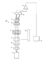
図1に示すように、本実施の形態の被測定物内の成分濃度の測定装置(以下、単に「測定装置」ともいう)1は、直線偏光を出射する光源としての半導体レーザ2と、半導体レーザ2からの直線偏光が入射され、入射された光の偏光状態を時間的に変化させて、媒質中の微粒子による光散乱を示す被測定物4に照射する手段において、入射された光の偏光状態を時間的に変化させる手段としての位相変調器3と、被測定物4を透過した光を偏光分離する手段としての偏光ビームスプリッタ5と、偏光分離された2つの偏光をそれぞれ検出する第1及び第2の光検出器6、7と、偏光分離された2つの偏光の検出信号を差動演算する手段としての差動増幅器8とを備えている。そして、当該測定装置1においては、差動増幅器8によって得られる差分信号が計測信号として利用される。また、差動増幅器8によって得られた計測信号は、パーソナルコンピュータ9へ入力され、そこで信号処理が行われる。
As shown in FIG. 1, a component concentration measuring device (hereinafter also simply referred to as “measuring device”) 1 in an object to be measured according to the present embodiment includes a
本実施の形態においては、直線偏光を出射する光源として半導体レーザ2が用いられている。半導体レーザ2は、小型で高効率であることから、測定装置1の安定化、小型化を図ることが可能となる。また、本実施の形態においては、自然発光成分を除去して、より精度を高めるために、図1に示すように、半導体レーザ2と位相変調器3との間に偏光子10が配置されている。しかし、偏光子10は、測定装置1の必須の構成要素ではない。尚、直線偏光を出射する光源としては、偏光子を備えた発光ダイオードを用いることもできる。この場合、発光ダイオードからの光は、偏光子を通して直線偏光に変換される。そして、このように、直線偏光を出射する光源として偏光子を備えた発光ダイオードを用いれば、より安価な測定装置を提供することが可能となる。
In the present embodiment, the
また、位相変調器3へ入射させる光はコリメート光であるのが望ましいため、本実施の形態においては、図1に示すように、半導体レーザ2と位相変調器3との間にコリメートレンズ11が配置されている。しかし、コリメートレンズ11は、測定装置1の必須の構成要素ではない。
Further, since it is desirable that the light incident on the
半導体レーザ2から出射される光の波長は、生体の光の窓と呼ばれる光が透過しやすい600nm〜1200nmであるのが望ましい。
The wavelength of the light emitted from the
位相変調器3としては、例えば、ニオブ酸リチウム、BSO(ビスマス・シリコン・オキサイド)等の電気光学結晶や液晶を用いたものを利用することができ、この位相変調器3は、位相変調器制御回路12によって制御される。そして、これにより、位相変調器3に入射した直線偏光を、楕円偏光、さらには、入射された直線偏光の偏光面から90°偏光面が回転した直線偏光へ変化させることが可能となる。
As the
第1及び第2の光検出器6、7としては、例えば、フォトダイオードや光電子増倍管等の光電変換素子を用いることができる。 As the 1st and 2nd photodetectors 6 and 7, photoelectric conversion elements, such as a photodiode and a photomultiplier tube, can be used, for example.
尚、本実施の形態においては、被測定物4を透過した光を偏光分離する手段として偏光ビームスプリッタ5を用いているが、その他、偏光回折格子、グラントムソンプリズム、ウォラストンプリズム、ローションプリズム、ビームディスプレイサなどを用いることもできる。
In the present embodiment, the
また、偏光ビームスプリッタ5の後、第1及び第2の光検出器6、7の直前、被測定物4の光透過位置に、被測定物4を照射する光の直径と同程度の直径のピンホール(図示せず)を散乱光除去のために設けてもよい。
In addition, after the
次に、以上の構成を備えた測定装置1を用いて計測信号を得る方法について、図1を参照しながら説明する。
Next, a method for obtaining a measurement signal using the
半導体レーザ2からの直線偏光は、コリメートレンズ11によってコリメートされ、偏光子10を透過した後、位相変調器3に入射される。位相変調器3によって偏光状態が時間的に変化した光は、被測定物4(血糖値測定(グルコース濃度の測定)においては、指や耳たぶ等)に照射される。被測定物4を透過した光は、偏光ビームスプリッタ5によって偏光分離され、偏光分離された2つの偏光は、それぞれ、第1及び第2の光検出器6、7によって検出される。それぞれ第1及び第2の光検出器6、7によって検出された検出信号は、差動増幅器8に入力され、差動増幅器8からは、偏光分離された2つの偏光の検出信号の差分信号が計測信号として出力される。
The linearly polarized light from the
被測定物4を透過し、偏光分離された後、第1及び第2の光検出器6、7によって検出される光には、「準直進光成分」と「回り込み成分」とが含まれる。ここで、準直進光成分とは、検出器に到達するまでの散乱回数が少なく、散乱媒質中を検出器に向かって略直線的に進行する経路を通過してきた光のことである。このように、準直進光成分は、散乱回数が少なく、散乱時に受ける偏光の解消度が小さい。従って、準直進光成分は、被測定物に照射される光の偏光状態を保存する。これに対し、回り込み成分は、散乱回数が多いため、偏光の解消度が大きく、無偏光となる。
The light detected by the first and second photodetectors 6 and 7 after passing through the
よって、回り込み成分は、偏光分離された後、偏光ビームスプリッタ5の偏光分離面の入射面内で振動している偏光成分(p偏光)、及び、入射面と直交する面内で振動している偏光成分(s偏光)と共に、被測定物4に照射される光の偏光に、つまり、位相変調器3での偏光状態の時間変調に関わらず一定強度の信号成分として、第1及び第2の光検出器6、7によって検出される。
Therefore, the sneak component is polarized and separated and then oscillated in the polarization component (p-polarized light) oscillating in the incident plane of the polarization splitting surface of the
これに対して、準直進光成分は、被測定物4に照射される光の偏光に、つまり、位相変調器3での偏光状態の時間変調に同期して強度が変化する変調信号として、第1及び第2の光検出器6、7によって検出される。
On the other hand, the quasi-straight light component is a modulated signal whose intensity changes in synchronization with the polarization of the light irradiated on the
つまり、第1の光検出器(p偏光光検出器)6、第2の光検出器(s偏光光検出器)7の両方において、回り込み成分に起因する一定強度の信号成分に、準直進光成分の変調信号が乗った信号が検出される(それぞれの検出器によって検出される信号を「p偏光側光信号」、「s偏光側光信号」という)。 That is, in both the first photodetector (p-polarized light detector) 6 and the second photodetector (s-polarized light detector) 7, the quasi-straight light is converted into a signal component having a constant intensity due to the wraparound component. A signal carrying a component modulation signal is detected (the signals detected by the respective detectors are referred to as “p-polarization side optical signal” and “s-polarization side optical signal”).
ここで、半導体レーザ2からの直線偏光(入射光の直線偏光)を、位相変調器3において、時間tでp偏光に相当する直線偏光から楕円偏光を経てs偏光に相当する直線偏光となるように偏光状態を変化させた場合、例えば、入射光の直線偏光がp偏光に相当する直線偏光となる瞬間では、被測定物4を透過した光の準直進光成分は全てp偏光側へ偏光分離され、入射光の直線偏光がs偏光に相当する直線偏光となる瞬間では、被測定物4を透過した光の準直進光成分は全てs偏光側へ偏光分離されるため、p偏光側に設けられた第1の光検出器(p偏光光検出器)6とs偏光側に設けられた第2の光検出器(s偏光光検出器)7によって得られる準直進光成分の強度変化は、互いに強弱が逆転したものとなる(図2の一点鎖線によって表された波形と二点鎖線によって表された波形を参照)。
Here, the linearly polarized light (linearly polarized light of incident light) from the
そこで、p偏光側光信号とs偏光側光信号の差分を取れば、回り込み成分がキャンセルされ、準直進光成分の振幅(強度)が2倍になった信号が得られる(図2の実線によって表された波形を参照)。 Therefore, if the difference between the p-polarization side optical signal and the s-polarization side optical signal is taken, a wraparound component is canceled and a signal in which the amplitude (intensity) of the quasi-straight light component is doubled can be obtained (by the solid line in FIG. 2). (See waveform shown).
ここで、レーザノイズや生体の局所的な変動(脈波、呼吸等)が起こった場合、その影響は、第1の光検出器(p偏光光検出器)6、第2の光検出器(s偏光光検出器)7の両方に、同時間に同量のノイズとして重畳する。これらのノイズは、第1の光検出器(p偏光光検出器)6からの信号と第2の光検出器(s偏光光検出器)7からの信号の差分を取ることによってキャンセルすることができる。そして、これにより、前記ノイズの影響を小さくすることができ、より高品質な準直進光成分の信号を得ることができる。 Here, when a laser noise or a local variation (pulse wave, respiration, etc.) of a living body occurs, the influence thereof is the first photodetector (p-polarized photodetector) 6, the second photodetector ( The same amount of noise is superimposed on both the s-polarized light detectors 7 at the same time. These noises can be canceled by taking the difference between the signal from the first photodetector (p-polarized light detector) 6 and the signal from the second photodetector (s-polarized light detector) 7. it can. As a result, the influence of the noise can be reduced, and a higher-quality quasi-straight light component signal can be obtained.
以上のようにして得られた差分信号は、パーソナルコンピュータ9へ入力され、その後の信号処理により、散乱係数の変化、さらにはグルコース濃度などの成分濃度が求められる。
The difference signal obtained as described above is input to the
尚、図2においては、準直進光成分の強度の時間変化が正弦波となるように、入射された光の偏光状態を時間的に変化させた場合を示しているが、必ずしもかかる構成に限定されるものではない。例えば、準直進光成分の強度の時間変化が矩形波、三角波となるように、入射された光の偏光状態を時間的に変化させるようにしてもよい。 FIG. 2 shows a case where the polarization state of the incident light is changed with time so that the temporal change of the intensity of the quasi-straight light component becomes a sine wave. Is not to be done. For example, the polarization state of the incident light may be temporally changed so that the temporal change in the intensity of the quasi-straight light component is a rectangular wave or a triangular wave.
[実施の形態2]
図3は、本発明の実施の形態2における被測定物内の成分濃度の測定装置を示す概略構成図である。
[Embodiment 2]
FIG. 3 is a schematic configuration diagram showing an apparatus for measuring a component concentration in a measurement object in
図3に示す測定装置13の構成は、差動増幅器8からの差分信号を、位相変調器3を制御している位相変調器制御回路12と同期したロックインアンプ14を用いて同期検波を行い、差動増幅器8からの差分信号(計測信号)の中から位相変調器3での偏光変化に同期して変化する成分(準直進光成分)を抽出している点のみが、上記実施の形態1の測定装置1の構成(図1参照)と異なっている。従って、上記実施の形態1の測定装置1を構成する部材と同一の部材については同一の参照符号を付し、それらの説明は省略する。
The configuration of the
ロックインアンプ14を用いて、差分信号の中から準直進光成分の抽出を行うことにより、例えば、第1及び第2の光検出器6、7や差動増幅器8において発生したノイズを除去して、より高品質な信号を得ることが可能となる。
For example, noise generated in the first and second photodetectors 6 and 7 and the
ロックインアンプ14からの出力信号は、パーソナルコンピュータ9へ入力され、その後の信号処理により、散乱係数の変化、さらにはグルコース濃度などの成分濃度が求められる。
An output signal from the lock-in
[実施の形態3]
図4は、本発明の実施の形態3における被測定物内の成分濃度の測定装置を示す概略構成図である。
[Embodiment 3]
FIG. 4 is a schematic configuration diagram showing an apparatus for measuring a component concentration in a measurement object in
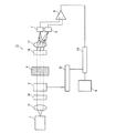
図4に示す測定装置15の構成は、被測定物4を透過した光を偏光分離する手段として偏光ビームスプリッタ5の代わりに偏光回折格子16を用いている点が、上記実施の形態1の測定装置1の構成(図1参照)と異なっている。従って、上記実施の形態1の測定装置1を構成する部材と同一の部材については同一の参照符号を付し、それらの説明は省略する。このように被測定物4を透過した光を偏光分離する手段として偏光回折格子16を用いることにより、より小型で安価な成分濃度の測定装置を提供することが可能となる。
The configuration of the
偏光回折格子16は、入射される偏光の向きによって、各次回折光へ回折される回折効率が異なる回折格子である。
The
偏光回折格子16は、複屈折を有する光学媒質と等方性媒質とを交互に配置することによって得られる。複屈折を有する光学媒質の材料としては、例えば、液晶分子がある。また、等方性媒質の材料としては、透明なガラス、プラスチック、又は紫外線硬化樹脂等がある。
The
例えば、屈折率が複屈折を有する液晶の常光屈折率noと同じである等方性媒質に、常光性偏光と異常光性偏光の位相差が1λ(λは使用波長)である鋸状の溝を形成し、液晶分子の長軸方向が揃うように液晶を溝に充填することにより、常光偏光が回折せず異常光偏光の略全てが1つの回折次数の回折光に回折する偏光回折格子16を得ることができる。以上の構成に限らず、常光屈折率noと異常光屈折率neの平均値である屈折率の等方性媒質に、常光性偏光と異常光性偏光の位相差が2λ(λは使用波長)である三角溝を形成し、液晶分子の長軸方向が揃うように液晶を溝に充填するようにしてもよい。この場合には、常光偏光と異常光偏光のそれぞれが別の1つの回折次数の回折光となるように回折する。 For example, in an isotropic medium refractive index is the same as the ordinary refractive index n o of the liquid crystal having birefringence, the phase difference of the ordinary light polarization and abnormal light polarization is serrated a 1 [lambda (lambda is the wavelength used) Polarization diffraction grating that forms grooves and fills the grooves with liquid crystal molecules so that the major axis direction of the liquid crystal molecules is aligned. 16 can be obtained. Not limited to the above configuration, the isotropic medium average value in the form of the refractive index of the ordinary refractive index n o and extraordinary refractive index n e, the phase difference of the ordinary light polarization and abnormal light polarization is 2 [lambda] (lambda is used A triangular groove having a wavelength) may be formed, and the liquid crystal may be filled in the groove so that the major axis directions of the liquid crystal molecules are aligned. In this case, the ordinary light polarization and the extraordinary light polarization are diffracted so as to be diffracted light of one different diffraction order.
また、図4に示す測定装置15においては、偏光回折格子16の直後にレンズ17が設けられている。レンズ17と第1及び第2の光検出器6、7は、レンズ17から第1及び第2の光検出器6、7までの距離がレンズ17の焦点距離となるように配置されている。この構成によれば、偏光回折格子16によって分離されたそれぞれの偏光を、それぞれ別の位置に集光することができ、第1及び第2の光検出器6、7の小型化が可能となる。
In the measuring
また、図4に示す測定装置15においては、2つの光検出器(第1及び第2の光検出器6、7)を用いているが、市販の2分割光検出器を用いて、各偏光をそれぞれ検出するようにしてもよい。
In addition, in the
また、上記実施の形態2と同様に、差動増幅器8からの差分信号を、位相変調器3を制御している位相変調器制御回路12と同期したロックインアンプ14を用いて同期検波を行い、差動増幅器8からの差分信号(計測信号)の中から位相変調器3での偏光変化に同期して変化する成分(準直進光成分)を抽出するようにしてもよい(図5参照)。
Similarly to the second embodiment, the differential signal from the
ロックインアンプ14を用いて、差分信号の中から準直進光成分の抽出を行うことにより、例えば、第1及び第2の光検出器6、7や差動増幅器8において発生したノイズを除去して、より高品質な信号を得ることが可能となる。
For example, noise generated in the first and second photodetectors 6 and 7 and the
ロックインアンプ14からの出力信号は、パーソナルコンピュータ9へ入力され、その後の信号処理により、散乱係数の変化、さらにはグルコース濃度などの成分濃度が求められる。
An output signal from the lock-in
[実施の形態4]
図6は、本発明の実施の形態4における被測定物内の成分濃度の測定装置を示す概略構成図である。
[Embodiment 4]
FIG. 6 is a schematic configuration diagram showing a component concentration measuring apparatus in a measurement object in
図6に示す測定装置18の構成は、入射された光の偏光状態を時間的に変化させる手段として位相変調器3の代わりに回転する位相板19を用いている点が、上記実施の形態1の測定装置1の構成(図1参照)と異なっている。従って、上記実施の形態1の測定装置1を構成する部材と同一の部材については同一の参照符号を付し、それらの説明は省略する。
The configuration of the measuring
回転する位相板19としては、例えば、1/2波長板を用いることができ、この位相板19の回転は、モータ20によって制御される。
For example, a half-wave plate can be used as the
半導体レーザ2からの直線偏光が、その偏光面が1/2波長板の主方向に対してθ°の方位角で1/2波長板へ入射された場合には、直線偏光のままその偏光面が2×θ°回転する。よって、位相板(1/2波長板)19が1回転すると、偏光面は2回転する。
When the linearly polarized light from the
また、上記実施の形態2と同様に、差動増幅器8からの差分信号を、回転する位相板19を制御しているモータ20と同期したロックインアンプ21を用いて同期検波を行い、差動増幅器8からの差分信号(計測信号)の中から回転する位相板19での偏光変化に同期して変化する成分(準直進光成分)を抽出するようにしてもよい(図7参照)。
Similarly to the second embodiment, the differential signal from the
この場合、各偏光分離された偏光の強度は、位相板(1/2波長板)19の1回転に対して4周期の変化をするので、位相板(1/2波長板)19の回転数の4倍の周波数をロックインアンプ21の参照信号として同期検波を行う。
In this case, the intensity of the polarized light separated from each polarization changes in four periods with respect to one rotation of the phase plate (1/2 wavelength plate) 19, so the number of rotations of the phase plate (1/2 wavelength plate) 19. Is used as a reference signal for the lock-in
ロックインアンプ21を用いて、差分信号の中から準直進光成分の抽出を行うことにより、例えば、第1及び第2の光検出器6、7や差動増幅器8において発生したノイズを除去して、より高品質な信号を得ることが可能となる。
For example, noise generated in the first and second photodetectors 6 and 7 and the
本発明の被測定物内の成分濃度の測定装置は、媒質中の微粒子による光散乱を示す被測定物内の成分濃度の測定を行う場合に有用である。特に、本発明によれば、ヒト生体組織内の血液中の血糖濃度を測定するのに好適な非侵襲の測定装置(血糖値センサ)を実現することができる。 The apparatus for measuring the concentration of a component in the measurement object of the present invention is useful when measuring the concentration of a component in the measurement object that shows light scattering by fine particles in the medium. In particular, according to the present invention, it is possible to realize a non-invasive measurement device (blood glucose level sensor) suitable for measuring the blood glucose concentration in blood in a human biological tissue.
1、13、15、18 被測定物内の成分濃度の測定装置
2 半導体レーザ
3 位相変調器
4 被測定物
5 偏光ビームスプリッタ
6 第1の光検出器
7 第2の光検出器
8 差動増幅器
9 パーソナルコンピュータ
10 偏光子
11 コリメートレンズ
12 位相変調器制御回路
14、21 ロックインアンプ
16 偏光回折格子
17 レンズ
19 回転する位相板
20 モータ
1, 13, 15, 18 Device
Claims (9)
前記光源からの直線偏光が入射され、入射された光の偏光状態を時間的に変化させて、媒質中の微粒子による光散乱を示す被測定物に照射する手段と、
前記被測定物を透過した光を偏光分離する手段と、
前記偏光分離された2つの偏光をそれぞれ検出する光検出器と、
前記偏光分離された2つの偏光の検出信号を差動演算する手段とを備え、
前記差動演算する手段によって得られる差分信号を計測信号として利用することを特徴とする、被測定物内の成分濃度の測定装置。 A light source that emits linearly polarized light;
Means for irradiating an object to be measured which shows light scattering by fine particles in a medium by linearly polarized light from the light source being incident, changing the polarization state of the incident light with time, and
Means for polarizing and separating the light transmitted through the object to be measured;
A photodetector for detecting each of the two polarized lights separated from each other;
Means for differentially calculating a detection signal of the two polarized lights separated from each other,
An apparatus for measuring a concentration of a component in an object to be measured, wherein a differential signal obtained by the means for performing a differential operation is used as a measurement signal.
Priority Applications (1)
| Application Number | Priority Date | Filing Date | Title |
|---|---|---|---|
| JP2011010931A JP2012148034A (en) | 2011-01-21 | 2011-01-21 | Apparatus for measuring component concentration in object to be measured |
Applications Claiming Priority (1)
| Application Number | Priority Date | Filing Date | Title |
|---|---|---|---|
| JP2011010931A JP2012148034A (en) | 2011-01-21 | 2011-01-21 | Apparatus for measuring component concentration in object to be measured |
Publications (1)
| Publication Number | Publication Date |
|---|---|
| JP2012148034A true JP2012148034A (en) | 2012-08-09 |
Family
ID=46790913
Family Applications (1)
| Application Number | Title | Priority Date | Filing Date |
|---|---|---|---|
| JP2011010931A Withdrawn JP2012148034A (en) | 2011-01-21 | 2011-01-21 | Apparatus for measuring component concentration in object to be measured |
Country Status (1)
| Country | Link |
|---|---|
| JP (1) | JP2012148034A (en) |
Cited By (2)
| Publication number | Priority date | Publication date | Assignee | Title |
|---|---|---|---|---|
| WO2015136956A1 (en) * | 2014-03-12 | 2015-09-17 | ソニー株式会社 | Measurement device and measurement method |
| WO2022220185A1 (en) * | 2021-04-12 | 2022-10-20 | 富士フイルム株式会社 | Optical alignment layer exposure method |
-
2011
- 2011-01-21 JP JP2011010931A patent/JP2012148034A/en not_active Withdrawn
Cited By (4)
| Publication number | Priority date | Publication date | Assignee | Title |
|---|---|---|---|---|
| WO2015136956A1 (en) * | 2014-03-12 | 2015-09-17 | ソニー株式会社 | Measurement device and measurement method |
| CN106061385A (en) * | 2014-03-12 | 2016-10-26 | 索尼公司 | Measurement device and measurement method |
| JPWO2015136956A1 (en) * | 2014-03-12 | 2017-04-06 | ソニー株式会社 | Measuring apparatus and measuring method |
| WO2022220185A1 (en) * | 2021-04-12 | 2022-10-20 | 富士フイルム株式会社 | Optical alignment layer exposure method |
Similar Documents
| Publication | Publication Date | Title |
|---|---|---|
| US7961318B2 (en) | Circular birefringence refractometer: method and apparatus for measuring optical activity | |
| US4901728A (en) | Personal glucose monitor | |
| CN102262051B (en) | Optical sensing device and method for detecting sample using the same | |
| EP2909624B1 (en) | Simple sugar concentration sensor and method | |
| US7248905B2 (en) | Method of and apparatus for measuring concentration | |
| EP1387161A1 (en) | Angle-of-rotation measuring device and angle-of-rotation measuring method | |
| DE4242232A1 (en) | Measuring device for the non-invasive determination of the concentration of polarizing substances in the human body | |
| JP2015194359A (en) | Scattering spectrometer | |
| JP2007525658A (en) | Differential optical technique for chiral analysis | |
| JP4269079B2 (en) | Non-invasive measuring device for trace component concentration in scattering medium | |
| CN111513728A (en) | A multi-technology fusion non-invasive blood glucose detection device and measurement method | |
| Zhang et al. | Time-domain photoacoustic waveform analysis for glucose measurement | |
| EP4300059A1 (en) | Circularly polarized light illuminator, analysis device, and microscope | |
| JP2012148034A (en) | Apparatus for measuring component concentration in object to be measured | |
| JP4706028B2 (en) | Blood glucose level measuring apparatus and method | |
| CN1264006C (en) | High precision measuring device and method for angle of rotation | |
| JP4094975B2 (en) | Concentration measuring device | |
| JP2004020539A (en) | Infrared circular dichroism measuring instrument and infrared circular dichroism measuring method | |
| JP5905318B2 (en) | Circular polarized light source system and circular dichroism measurement system | |
| JP2019045247A (en) | Measurement device | |
| JP6080004B2 (en) | Parameter measuring apparatus, parameter measuring method, and program | |
| JP5345439B2 (en) | Component concentration analyzer and component concentration analysis method | |
| JP2015225021A (en) | Optical rotation characteristic measuring device for specimen in very small quantity | |
| WO1997033514A1 (en) | Method and apparatus for circular dichromatic analysis | |
| JP2004294355A (en) | Concentration measuring instrument |
Legal Events
| Date | Code | Title | Description |
|---|---|---|---|
| A300 | Withdrawal of application because of no request for examination |
Free format text: JAPANESE INTERMEDIATE CODE: A300 Effective date: 20140401 |