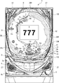
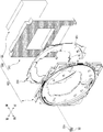
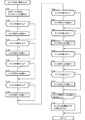
まず、遊技機の一例であるパチンコ遊技機1の全体の構成について説明する。図1はパチンコ遊技機1を正面からみた正面図である。図2は、パチンコ遊技機を示す背面図である。図3は、主基板における回路構成の一例を示すブロック図である。図4は、パチンコ遊技機を開放した状態を示す斜視図である。図5は、遊技盤ユニットを示す分解斜視図である。図6は、各入賞口におけるスイッチの配設状況を示す概略図である。
First, the overall configuration of a pachinko gaming machine 1 that is an example of a gaming machine will be described. FIG. 1 is a front view of the pachinko gaming machine 1 as seen from the front. FIG. 2 is a rear view showing the pachinko gaming machine. FIG. 3 is a block diagram illustrating an example of a circuit configuration on the main board. FIG. 4 is a perspective view showing a state in which the pachinko gaming machine is opened. FIG. 5 is an exploded perspective view showing the game board unit. FIG. 6 is a schematic diagram showing the arrangement of switches at each winning opening.
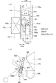
パチンコ遊技機1は、図1、図2及び図4に示すように、縦長の方形枠状に形成された外枠100と、外枠100に開閉可能に取り付けられた前面枠101と、で主に構成されている。前面枠101の前面には、ガラス扉枠102及び下扉枠103がそれぞれ左側辺を中心に開閉可能に設けられている。
As shown in FIGS. 1, 2, and 4, the pachinko gaming machine 1 mainly includes an outer frame 100 formed in a vertically long rectangular frame shape and a front frame 101 attached to the outer frame 100 so as to be openable and closable. It is configured. A glass door frame 102 and a lower door frame 103 are provided on the front surface of the front frame 101 so as to be openable and closable around the left side.
下扉枠103の下部表面には打球供給皿(上皿)3がある。打球供給皿3の下部には、打球供給皿3に収容しきれない遊技球を貯留する余剰球受皿4(下皿)や、打球を発射する打球操作ハンドル(操作ノブ)5が設けられている。また、ガラス扉枠102の背面には、遊技盤6が前面枠101に対して着脱可能に取り付けられている。
A hitting ball supply tray (upper plate) 3 is provided on the lower surface of the lower door frame 103. Under the hitting ball supply tray 3, there are provided an extra ball receiving tray 4 (lower plate) for storing game balls that cannot be accommodated in the hitting ball supply tray 3 and a hitting operation handle (operation knob) 5 for firing the hitting ball. . The game board 6 is detachably attached to the front frame 101 on the back surface of the glass door frame 102.
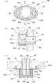
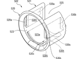
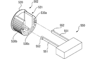
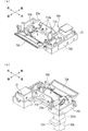
遊技盤6は、図4に示すように、遊技領域7が前面に形成された合成樹脂製の盤面板200と、所定の厚み幅寸法を有し、盤面板200を取り付ける取付面が前面に設けられたスペーサ部材250と、から構成され、該遊技盤6の背面側には、後述する導光板ユニット350や、演出表示装置9及び演出制御基板80等を含む変動表示制御ユニット49等の遊技に関連する遊技用部品が組み付けられる遊技用部品ユニット300が一体的に組み付けられている(図5参照)。
As shown in FIG. 4, the game board 6 has a board surface plate 200 made of synthetic resin with a game area 7 formed on the front surface, and a mounting surface to which the board surface plate 200 is attached. In the back side of the game board 6, a light guide plate unit 350, a variable display control unit 49 including an effect display device 9, an effect control board 80, and the like are provided on the back side of the game board 6. A gaming component unit 300 to which related gaming components are assembled is integrally assembled (see FIG. 5).
遊技盤6と遊技用部品ユニット300とが一体的に組み付けられた遊技盤ユニット400(図5参照)を前面枠101の前面に取り付けるには、遊技盤6の左端部を図中太矢印に示すように、前面枠101に形成された縦長長方形状の開口部115の左上下位置に設けられた係止凹部116a,116bに、遊技盤6の左端部を差し込んだ状態で、右端部を盤押え金具692,693で係止することにより取り付けられるようになっている。係止凹部116a,116bには後述する盤押えバネ690,691が設けられており、係止凹部116a,116bに係止された遊技盤6の前後のガタツキが防止されている。盤面板200が取り付けられた状態において、該遊技盤6の背面に設けられた遊技用部品ユニット300が開口部115を介して前面枠101の背面側に臨むようになっている。
To attach the game board unit 400 (see FIG. 5) in which the game board 6 and the game component unit 300 are integrally assembled to the front surface of the front frame 101, the left end portion of the game board 6 is indicated by a thick arrow in the figure. As described above, with the left end of the game board 6 being inserted into the locking recesses 116a and 116b provided at the upper left and right positions of the vertically long rectangular opening 115 formed in the front frame 101, the right end is pressed against the board. It can be attached by locking with metal fittings 692 and 693. Board holding springs 690 and 691 described later are provided in the locking recesses 116a and 116b, respectively, to prevent back and forth play of the game board 6 locked in the locking recesses 116a and 116b. In a state where the board surface plate 200 is attached, the game component unit 300 provided on the back surface of the game board 6 faces the back side of the front frame 101 through the opening 115.
図1に戻って、遊技領域7の中央付近には、それぞれが演出用の飾り図柄(演出図柄)を可変表示する複数の可変表示部を含む演出表示装置(飾り図柄表示装置)9が設けられている。演出表示装置9には、例えば「左」、「中」、「右」の3つの可変表示部(図柄表示エリア)がある。演出表示装置9は、第1特別図柄表示器8aまたは第2特別図柄表示器8bによる特別図柄の可変表示期間中に、装飾用(演出用)の図柄としての演出図柄の可変表示を行う。演出図柄の可変表示を行う演出表示装置9は、演出制御基板80に搭載されている演出制御用マイクロコンピュータによって制御される。
Returning to FIG. 1, in the vicinity of the center of the game area 7, there is provided an effect display device (decorative symbol display device) 9 including a plurality of variable display units each variably displaying an effect decorative symbol (effect symbol). ing. The effect display device 9 includes, for example, three variable display portions (symbol display areas) of “left”, “middle”, and “right”. The effect display device 9 variably displays the effect symbol as a decoration (effect) symbol during the variable display period of the special symbol by the first special symbol indicator 8a or the second special symbol indicator 8b. The effect display device 9 that performs variable display of effect symbols is controlled by an effect control microcomputer mounted on the effect control board 80.
遊技盤6における右側下部位置には、第1識別情報としての第1特別図柄を可変表示する第1特別図柄表示器(第1可変表示手段)8aが設けられている。この実施例では、第1特別図柄表示器8aは、0〜9の数字を可変表示可能な簡易で小型の表示器(例えば7セグメントLED)で実現されている。すなわち、第1特別図柄表示器8aは、0〜9の数字(または、記号)を可変表示するように構成されている。また、第1特別図柄表示器8aの上方位置には、第2識別情報としての第2特別図柄を可変表示する第2特別図柄表示器(第2可変表示手段)8bが設けられている。第2特別図柄表示器8bは、0〜9の数字を可変表示可能な簡易で小型の表示器(例えば7セグメントLED)で実現されている。すなわち、第2特別図柄表示器8bは、0〜9の数字(または、記号)を可変表示するように構成されている。
A first special symbol display (first variable display means) 8a for variably displaying a first special symbol as first identification information is provided at a lower right position on the game board 6. In this embodiment, the first special symbol display 8a is realized by a simple and small display (for example, 7 segment LED) capable of variably displaying numbers 0 to 9. In other words, the first special symbol display 8a is configured to variably display numbers (or symbols) from 0 to 9. A second special symbol display (second variable display means) 8b for variably displaying the second special symbol as the second identification information is provided above the first special symbol display 8a. The second special symbol display 8b is realized by a simple and small display (for example, 7 segment LED) capable of variably displaying numbers 0 to 9. That is, the second special symbol display 8b is configured to variably display numbers (or symbols) from 0 to 9.
この実施例では、第1特別図柄の種類と第2特別図柄の種類とは同じ(例えば、ともに0〜9の数字)であるが、種類が異なっていてもよい。また、第1特別図柄表示器8aおよび第2特別図柄表示器8bは、それぞれ、例えば2つの7セグメントLED等を用いて00〜99の数字(または、2桁の記号)を可変表示するように構成されていてもよい。
In this embodiment, the type of the first special symbol and the type of the second special symbol are the same (for example, both 0 to 9), but the types may be different. The first special symbol display 8a and the second special symbol display 8b each variably display a number (or a two-digit symbol) from 0 to 99 using, for example, two 7-segment LEDs. It may be configured.
以下、第1特別図柄と第2特別図柄とを特別図柄と総称することがあり、第1特別図柄表示器8aと第2特別図柄表示器8bとを特別図柄表示器と総称することがある。
Hereinafter, the first special symbol and the second special symbol may be collectively referred to as a special symbol, and the first special symbol indicator 8a and the second special symbol indicator 8b may be collectively referred to as a special symbol indicator.
第1特別図柄の可変表示は、可変表示の実行条件である第1始動条件が成立(例えば、遊技球が第1始動入賞口13aに入賞したこと)した後、可変表示の開始条件(例えば、保留記憶数が0でない場合であって、第1特別図柄の可変表示が実行されていない状態であり、かつ、大当り遊技が実行されていない状態)が成立したことにもとづいて開始され、可変表示時間(変動時間)が経過すると表示結果(停止図柄)を導出表示する。また、第2特別図柄の可変表示は、可変表示の実行条件である第2始動条件が成立(例えば、遊技球が第2始動入賞口13bに入賞したこと)した後、可変表示の開始条件(例えば、保留記憶数が0でない場合であって、第2特別図柄の可変表示が実行されていない状態であり、かつ、大当り遊技が実行されていない状態)が成立したことにもとづいて開始され、可変表示時間(変動時間)が経過すると表示結果(停止図柄)を導出表示する。尚、入賞とは、入賞口などのあらかじめ入賞領域として定められている領域に遊技球が入ったことである。また、表示結果を導出表示するとは、図柄(識別情報の例)を最終的に停止表示させることである。
The variable display of the first special symbol is a variable display start condition (for example, after the game ball has won the first start winning opening 13a) after the first start condition, which is the variable display execution condition, is established (for example, When the number of reserved memories is not 0, the variable display of the first special symbol is not executed, and the variable display is started based on the fact that the big hit game is not executed) When time (fluctuation time) elapses, a display result (stop symbol) is derived and displayed. In addition, the variable display of the second special symbol is a variable display start condition (for example, that the game ball has won the second start winning opening 13b) after the second start condition, which is a variable display execution condition, is satisfied (for example, For example, when the number of reserved memories is not 0, the variable display of the second special symbol is not executed, and the big hit game is not executed) is started, When the variable display time (variation time) elapses, the display result (stop symbol) is derived and displayed. Note that winning means that a game ball has entered a predetermined area such as a winning opening. Deriving and displaying the display result is to finally stop and display a symbol (an example of identification information).
演出表示装置9は、第1特別図柄表示器8aでの第1特別図柄の可変表示時間中、および第2特別図柄表示器8bでの第2特別図柄の可変表示時間中に、装飾用(演出用)の図柄としての演出図柄(飾り図柄ともいう)の可変表示を行う。第1特別図柄表示器8aにおける第1特別図柄の可変表示と、演出表示装置9における演出図柄の可変表示とは同期している。また、第2特別図柄表示器8bにおける第2特別図柄の可変表示と、演出表示装置9における演出図柄の可変表示とは同期している。同期とは、可変表示の開始時点および終了時点がほぼ同じ(全く同じでもよい。)であって、可変表示の期間がほぼ同じ(全く同じでもよい。)であることをいう。また、第1特別図柄表示器8aにおいて大当り図柄が停止表示されるときと、第2特別図柄表示器8bにおいて大当り図柄が停止表示されるときには、演出表示装置9において大当りを想起させるような演出図柄の組合せが停止表示される。
The effect display device 9 is for decoration (effect) during the variable display time of the first special symbol on the first special symbol display 8a and during the variable display time of the second special symbol on the second special symbol display 8b. Display design (also referred to as a decorative design) as a design. The variable display of the first special symbol on the first special symbol display 8a and the variable display of the effect symbol on the effect display device 9 are synchronized. Further, the variable display of the second special symbol on the second special symbol display 8b and the variable display of the effect symbol on the effect display device 9 are synchronized. Synchronous means that the start time and end time of variable display are substantially the same (may be exactly the same) and the variable display period is substantially the same (may be exactly the same). Further, when the jackpot symbol is stopped and displayed on the first special symbol display 8a and when the jackpot symbol is stopped and displayed on the second special symbol display 8b, the effect display device 9 reminds the jackpot The combination of is stopped and displayed.
演出表示装置9の下方には、第1始動入賞口13aを有する入賞装置が設けられている。第1始動入賞口13aに入賞した遊技球は、遊技盤6の背面に導かれ、第1始動口スイッチ14a(例えば、近接スイッチ)及び第1入賞確認スイッチ14b(例えば、フォトセンサ)によって検出される。
Below the effect display device 9, a winning device having a first start winning port 13a is provided. The game ball won in the first start winning opening 13a is guided to the back of the game board 6, and is detected by the first start opening switch 14a (for example, proximity switch) and the first winning confirmation switch 14b (for example, photo sensor). The
また、第1始動入賞口(第1始動口)13aを有する入賞装置の下側には、遊技球が入賞可能な第2始動入賞口13bを有する可変入賞球装置15が設けられている。第2始動入賞口(第2始動口)13bに入賞した遊技球は、遊技盤6の背面に導かれ、第2始動口スイッチ15a及び第2入賞確認スイッチ15bによって検出される。可変入賞球装置15は、ソレノイド16によって開状態とされる。可変入賞球装置15が開状態になることによって、遊技球が第2始動入賞口13bに入賞可能になり(始動入賞し易くなり)、遊技者にとって有利な状態になる。可変入賞球装置15が開状態になっている状態では、第1始動入賞口13aよりも、第2始動入賞口13bに遊技球が入賞しやすい。また、可変入賞球装置15が閉状態になっている状態では、遊技球は第2始動入賞口13bに入賞しない。尚、可変入賞球装置15が閉状態になっている状態において、入賞はしづらいものの、入賞することは可能である(すなわち、遊技球が入賞しにくい)ように構成されていてもよい。
A variable winning ball device 15 having a second starting winning port 13b through which a game ball can be won is provided below the winning device having the first starting winning port (first starting port) 13a. The game ball that has won the second start winning opening (second start opening) 13b is guided to the back of the game board 6 and detected by the second start opening switch 15a and the second winning confirmation switch 15b. The variable winning ball device 15 is opened by a solenoid 16. When the variable winning ball apparatus 15 is in the open state, the game ball can be won in the second start winning opening 13b (it is easy to start winning), which is advantageous for the player. In a state where the variable winning ball device 15 is in the open state, it is easier for the game ball to win the second starting winning port 13b than the first starting winning port 13a. In addition, in a state where the variable winning ball device 15 is in the closed state, the game ball does not win the second start winning opening 13b. In the state where the variable winning ball device 15 is in the closed state, it may be configured that the winning is possible (that is, it is difficult for the gaming ball to win) although it is difficult to win a prize.
また、第1始動口スイッチ14aと第1入賞確認スイッチ14bの検出結果及び第2始動口スイッチ15aと第2入賞確認スイッチ15bの検出結果にもとづいて異常入賞の発生の有無が判定され、異常入賞の発生を検出したことにもとづいてセキュリティ信号が外部出力される。
In addition, it is determined whether or not an abnormal winning has occurred based on the detection results of the first starting port switch 14a and the first winning confirmation switch 14b and the detection results of the second starting port switch 15a and the second winning confirmation switch 15b. A security signal is externally output based on the detection of the occurrence of.
以下、第1始動入賞口13aと第2始動入賞口13bとを総称して始動入賞口または始動口ということがある。
Hereinafter, the first start winning opening 13a and the second start winning opening 13b may be collectively referred to as a start winning opening or a starting opening.
可変入賞球装置15が開放状態に制御されているときには可変入賞球装置15に向かう遊技球は第2始動入賞口13bに極めて入賞しやすい。そして、第1始動入賞口13aは演出表示装置9の直下に設けられているが、演出表示装置9の下端と第1始動入賞口13aとの間の間隔をさらに狭めたり、第1始動入賞口13aの周辺で釘を密に配置したり、第1始動入賞口13aの周辺での釘配列を、遊技球を第1始動入賞口13aに導きづらくして、第2始動入賞口13bの入賞率の方を第1始動入賞口13aの入賞率よりもより高くするようにしてもよい。
When the variable winning ball device 15 is controlled to be in the open state, the game ball heading for the variable winning ball device 15 is very likely to win the second start winning port 13b. The first start winning opening 13a is provided directly below the effect display device 9, but the interval between the lower end of the effect display device 9 and the first start winning port 13a is further reduced, or the first start winning port is set. The winning rate of the second starting winning port 13b is such that the nails are densely arranged around 13a, or the nail arrangement around the first starting winning port 13a is difficult to guide the game ball to the first starting winning port 13a. You may make it make higher than the winning rate of the 1st start winning opening 13a.
第2特別図柄表示器8bの上部には、第1始動入賞口13aに入った有効入賞球数すなわち第1保留記憶数(保留記憶を、始動記憶または始動入賞記憶ともいう。)を表示する第1特別図柄保留記憶表示部と、該第1特別図柄保留記憶表示部とは別個に設けられ、第2始動入賞口13bに入った有効入賞球数すなわち第2保留記憶数を表示する第2特別図柄保留記憶表示部と、が設けられた例えば7セグメントLEDからなる特別図柄保留記憶表示器18が設けられている。第1特別図柄保留記憶表示部は、第1保留記憶数を入賞順に4個まで表示し、有効始動入賞がある毎に、点灯する表示器の数を1増やす。そして、第1特別図柄表示器8aでの可変表示が開始される毎に、点灯する表示器の数を1減らす。また、第2特別図柄保留記憶表示部は、第2保留記憶数を入賞順に4個まで表示し、有効始動入賞がある毎に、点灯する表示器の数を1増やす。そして、第2特別図柄表示器8bでの可変表示が開始される毎に、点灯する表示器の数を1減らす。尚、この例では、第1始動入賞口13aへの入賞による始動記憶数及び第2始動入賞口13bへの入賞による始動記憶数に上限数(4個まで)が設けられているが、上限数を4個以上にしてもよい。
In the upper part of the second special symbol display 8b, the number of effective winning balls that have entered the first start winning opening 13a, that is, the first reserved memory number (the reserved memory is also referred to as the start memory or the start prize memory) is displayed. A first special symbol reserved memory display section and the first special symbol reserved memory display section are provided separately, and a second special special display for displaying the number of effective winning balls that have entered the second start winning slot 13b, that is, the second reserved memory number. For example, a special symbol storage memory display unit 18 including a 7-segment LED provided with a symbol storage memory display unit is provided. The first special symbol reserved memory display unit displays up to four first reserved memory numbers in the order of winning, and increases the number of indicators that are turned on by 1 each time there is an effective start winning. Then, each time the variable display on the first special symbol display 8a is started, the number of indicators to be turned on is reduced by one. The second special symbol reserved memory display unit displays up to four second reserved memory numbers in the order of winning, and increases the number of indicators that are turned on by 1 each time there is an effective start winning. Then, each time the variable display on the second special symbol display 8b is started, the number of indicators to be turned on is reduced by one. In this example, the upper limit number (up to 4) is provided for the start memory number by winning to the first start winning port 13a and the start memory number by winning to the second start winning port 13b. May be four or more.
また、演出表示装置9の表示画面には、第1保留記憶数を表示する第1保留記憶表示部(図示略)と、第2保留記憶数を表示する第2保留記憶表示部(図示略)とが設けられている。尚、第1保留記憶数と第2保留記憶数との合計である合計数(合算保留記憶数)を表示する領域(合算保留記憶表示部)が設けられるようにしてもよい。そのように、合計数を表示する合算保留記憶表示部が設けられているようにすれば、可変表示の開始条件が成立していない実行条件の成立数の合計を把握しやすくすることができる。
On the display screen of the effect display device 9, a first reserved memory display unit (not shown) for displaying the first reserved memory number and a second reserved memory display unit (not shown) for displaying the second reserved memory number. And are provided. In addition, you may make it provide the area | region (sum total pending | holding memory display part) which displays the total number (sum total pending memory count) which is the sum total of the 1st pending memory count and the 2nd pending memory count. As described above, if the summation pending storage display section for displaying the total number is provided, it is possible to easily grasp the total number of execution conditions that are not satisfied with the variable display start condition.
尚、この実施例では、図1に示すように、第2始動入賞口13bに対してのみ開閉動作を行う可変入賞球装置15が設けられているが、第1始動入賞口13aおよび第2始動入賞口13bのいずれについても開閉動作を行う可変入賞球装置が設けられている構成であってもよい。
In this embodiment, as shown in FIG. 1, there is provided a variable winning ball device 15 that opens and closes only the second starting winning opening 13b. However, the first starting winning opening 13a and the second starting winning opening 13b are provided. A configuration in which a variable winning ball apparatus that performs an opening / closing operation may be provided for any of the winning openings 13b.
また、図1に示すように、可変入賞球装置15の下方には、遊技球が入賞可能な第1大入賞口23c(図6参照)を有する第1特別可変入賞球装置23が設けられている。第1大入賞口23cに入賞した遊技球は、遊技盤6の背面に導かれ、第1カウントスイッチ23a及び第3入賞確認スイッチ23bによって検出される。
Further, as shown in FIG. 1, a first special variable winning ball device 23 having a first big winning port 23c (see FIG. 6) through which a game ball can be won is provided below the variable winning ball device 15. Yes. The game ball that has won the first big prize opening 23c is guided to the back of the game board 6 and detected by the first count switch 23a and the third prize confirmation switch 23b.
第1特別図柄表示器8aに特定表示結果(大当り図柄)が導出表示されたとき、および第2特別図柄表示器8bに特定表示結果(大当り図柄)が導出表示されたときに生起する特定遊技状態(大当り遊技状態)においてソレノイド21によって後述する大入賞口扉704(図32参照)が開放状態に制御されることによって、入賞領域となる第1大入賞口23cが開状態とされる。第1特別可変入賞球装置23が開状態になることによって、遊技球が第1大入賞口23cに入賞可能になり(入賞し易くなり)、遊技者にとって有利な状態になる。第1特別可変入賞球装置23が開状態になっている状態では、第1大入賞口23cに遊技球が入賞しやすい。また、大入賞口扉704(図32参照)が閉止状態になっている場合、遊技球は第1大入賞口23cに入賞しない。尚、大入賞口扉704(図32参照)が閉止状態になっている場合において、入賞はしづらいものの、入賞することは可能である(すなわち、遊技球が入賞しにくい)ように構成されていてもよい。
A specific gaming state that occurs when a specific display result (big hit symbol) is derived and displayed on the first special symbol display 8a and when a specific display result (big hit symbol) is derived and displayed on the second special symbol display 8b In the (hit game state), the first prize-winning port 23c, which is a prize-winning area, is opened by the solenoid 21 controlling a prize-winning door 704 (see FIG. 32), which will be described later, to an open state. When the first special variable winning ball device 23 is in the open state, the game ball can be won in the first big winning opening 23c (it is easy to win), which is advantageous to the player. In a state where the first special variable winning ball apparatus 23 is in the open state, it is easy for a game ball to win the first big winning opening 23c. In addition, when the grand prize winning door 704 (see FIG. 32) is closed, the game ball does not win the first big prize winning opening 23c. It should be noted that when the grand prize opening door 704 (see FIG. 32) is in the closed state, it is difficult to win, but it is possible to win (that is, it is difficult for the game ball to win). May be.
また、第1カウントスイッチ23a及び第3入賞確認スイッチ23bの検出結果にもとづいて異常入賞の発生の有無が判定され、異常入賞の発生を検出したことにもとづいてセキュリティ信号が外部出力される。
Further, the presence / absence of an abnormal winning is determined based on the detection results of the first count switch 23a and the third winning confirmation switch 23b, and a security signal is externally output based on the detection of the abnormal winning.
第1カウントスイッチ23aによって遊技球が検出されたことに基づき、所定個数(例えば15個)の遊技球が賞球として払い出される。こうして、第1特別可変入賞球装置23において開放状態となった第1大入賞口23cを遊技球が通過(進入)したときには、例えば第1始動入賞口13aや第2始動入賞口13bといった、他の入賞口を遊技球が通過(進入)したときよりも多くの賞球が払い出される。したがって、第1特別可変入賞球装置23において第1大入賞口23cが開放状態となれば、遊技者にとって有利な第1状態となる。その一方で、第1特別可変入賞球装置23において第1大入賞口23cが閉止状態となれば、第1大入賞口23cに遊技球を通過(進入)させて賞球を得ることができないため、遊技者にとって不利な第2状態となる。
Based on the detection of game balls by the first count switch 23a, a predetermined number (for example, 15) of game balls are paid out as prize balls. Thus, when the game ball passes (enters) the first special winning opening 23c opened in the first special variable winning ball apparatus 23, for example, the first starting winning opening 13a and the second starting winning opening 13b, etc. More prize balls are paid out than when a game ball passes (enters) through the prize opening. Accordingly, if the first special winning opening 23c is opened in the first special variable winning ball apparatus 23, the first state is advantageous for the player. On the other hand, if the first special winning opening 23c is closed in the first special variable winning ball apparatus 23, the game ball cannot pass through (enter) the first big winning opening 23c and a prize ball cannot be obtained. The second state is disadvantageous for the player.
また、演出表示装置9の上方左側には、遊技球が入賞可能な第2大入賞口24cを有する第2特別可変入賞球装置24が設けられている。第2大入賞口24cに入賞した遊技球は、遊技盤6の背面に導かれ、第2カウントスイッチ24a及び第4入賞確認スイッチ24bによって検出される。
Further, on the upper left side of the effect display device 9, a second special variable winning ball device 24 having a second big winning port 24c through which a game ball can be won is provided. The game ball that has won the second grand prize opening 24c is guided to the back of the game board 6, and is detected by the second count switch 24a and the fourth winning confirmation switch 24b.
第1特別図柄表示器8aに特定表示結果(大当り図柄)が導出表示されたとき、および第2特別図柄表示器8bに特定表示結果(大当り図柄)が導出表示されたときに生起する特定遊技状態(大当り遊技状態)においてソレノイド22によって羽根部材600(図21参照)が開放状態に制御されることによって、入賞領域となる第2大入賞口24cが開状態とされ、遊技球が第2大入賞口24cに入賞可能になり(入賞し易くなり)、遊技者にとって有利な状態になる。第2特別可変入賞球装置24が開状態になっている状態では、第2大入賞口24cに遊技球が入賞しやすい。また、羽根部材600(図21参照)が閉止状態になっている場合、遊技球は第2大入賞口24cに入賞しない。尚、第2特別可変入賞球装置24が閉状態になっている場合において、入賞はしづらいものの、入賞することは可能である(すなわち、遊技球が入賞しにくい)ように構成されていてもよい。
A specific gaming state that occurs when a specific display result (big hit symbol) is derived and displayed on the first special symbol display 8a and when a specific display result (big hit symbol) is derived and displayed on the second special symbol display 8b In the (big hit game state), the solenoid member 22 controls the blade member 600 (see FIG. 21) to be in the open state, thereby opening the second big prize opening 24c serving as a winning area, and the game ball becomes the second big prize. It becomes possible to win a prize in the mouth 24c (it becomes easier to win), which is advantageous to the player. In a state where the second special variable winning ball device 24 is in the open state, it is easy for a game ball to win the second big winning port 24c. Further, when the blade member 600 (see FIG. 21) is in the closed state, the game ball does not win the second grand prize opening 24c. In the case where the second special variable winning ball device 24 is in the closed state, although it is difficult to win, it is possible to win (that is, it is difficult for the game ball to win). Good.
また、第2カウントスイッチ24a及び第4入賞確認スイッチ24bの検出結果にもとづいて異常入賞の発生の有無が判定され、異常入賞の発生を検出したことにもとづいてセキュリティ信号が外部出力される。
Further, the presence / absence of an abnormal winning is determined based on the detection results of the second count switch 24a and the fourth winning confirmation switch 24b, and a security signal is output to the outside based on the detection of the abnormal winning.
第2カウントスイッチ24aによって遊技球が検出されたことに基づき、所定個数(例えば15個)の遊技球が賞球として払い出される。こうして、第2特別可変入賞球装置24において開放状態となった第2大入賞口24cを遊技球が通過(進入)したときには、例えば第1始動入賞口13aや第2始動入賞口13bといった、他の入賞口を遊技球が通過(進入)したときよりも多くの賞球が払い出される。したがって、第2特別可変入賞球装置24が開放状態となれば、遊技者にとって有利な第1状態となる。その一方で、第2特別可変入賞球装置24において第2大入賞口24cが閉止状態となれば、第2大入賞口24cに遊技球を通過(進入)させて賞球を得ることができないため、遊技者にとって不利な第2状態となる。
Based on the detection of the game ball by the second count switch 24a, a predetermined number (for example, 15) of game balls are paid out as prize balls. Thus, when the game ball passes (enters) through the second big prize opening 24c that has been opened in the second special variable prize ball apparatus 24, for example, the first start prize opening 13a and the second start prize opening 13b, etc. More prize balls are paid out than when a game ball passes (enters) through the prize opening. Therefore, when the second special variable winning ball device 24 is in the open state, the first state is advantageous for the player. On the other hand, if the second special winning opening 24c is closed in the second special variable winning ball apparatus 24, the game ball cannot pass through (enter) the second large winning opening 24c and a prize ball cannot be obtained. The second state is disadvantageous for the player.
また、近接スイッチである第1始動口スイッチ14a(以下、第2始動口スイッチ15a、第1カウントスイッチ23a、第2カウントスイッチ24aも同様であるが、説明を省略する)の一方の端子には、電源基板から+12V電源電圧が供給されている。第1始動口スイッチ14aの他方の端子の電圧レベルである検出信号は、主基板31に入力される。主基板31において、検出信号は、入力ドライバ回路から遊技制御用マイクロコンピュータの入力ポートに入力される。また、第1始動口スイッチ14aの出力側には、一端が接地されている抵抗RとコンデンサCが接続されている。
Also, one terminal of the first start port switch 14a (hereinafter, the second start port switch 15a, the first count switch 23a, and the second count switch 24a are the same, but the description is omitted), which is a proximity switch. The + 12V power supply voltage is supplied from the power supply board. A detection signal that is the voltage level of the other terminal of the first start port switch 14 a is input to the main board 31. In the main board 31, the detection signal is input from the input driver circuit to the input port of the game control microcomputer. A resistor R and a capacitor C, one end of which is grounded, are connected to the output side of the first start port switch 14a.
近接スイッチである第1始動口スイッチ14aに設けられている穴を金属の遊技球が通過するとコイルに逆起電力が生じ、コイルの等価的な抵抗値が極めて大きくなる。従って、第1始動口スイッチ14aの出力は、0Vに近いローレベルになる。すなわち、検出信号は、ローレベルである。第1始動口スイッチ14aに設けられている穴を金属の遊技球が通過していない場合には、第1始動口スイッチ14aの出力は、+12Vがコイルと抵抗Rの抵抗値で分圧された値であり、ハイレベルであるとみなされるしきい値レベルを越える。すなわち、検出信号は、ハイレベルである。従って、本実施例では、遊技制御用マイクロコンピュータは、第1始動口スイッチ14aからの出力がハイレベルであれば第1始動口スイッチ14aがオフ状態であると判断することができ、第1始動口スイッチ14aからの出力がローレベルであれば第1始動口スイッチ14aがオン状態であると判断することができる(すなわち、第1始動口スイッチ14aの出力は負論理となっている)。尚、検出信号のレベルを入力ドライバ回路で論理反転してから遊技制御用マイクロコンピュータ156に入力するように構成してもよい。
When a metal game ball passes through a hole provided in the first start port switch 14a that is a proximity switch, a counter electromotive force is generated in the coil, and the equivalent resistance value of the coil becomes extremely large. Accordingly, the output of the first start port switch 14a becomes a low level close to 0V. That is, the detection signal is at a low level. When the metal game ball does not pass through the hole provided in the first start port switch 14a, the output of the first start port switch 14a is + 12V divided by the resistance value of the coil and the resistor R. The value exceeds a threshold level that is considered high. That is, the detection signal is at a high level. Therefore, in this embodiment, the game control microcomputer can determine that the first start port switch 14a is in the OFF state if the output from the first start port switch 14a is at a high level. If the output from the mouth switch 14a is at a low level, it can be determined that the first start port switch 14a is in the ON state (that is, the output of the first start port switch 14a is negative logic). The detection signal level may be logically inverted by an input driver circuit and then input to the game control microcomputer 156.
フォトセンサである第1入賞確認スイッチ14b(以下、第2入賞確認スイッチ15b、第3入賞確認スイッチ23b、第4入賞確認スイッチ24bも同様であるが、説明を省略する)は、発光する発光ダイオード(LED)と受光して電流を出力するフォトトランジスタとで構成されている。発光ダイオードおよびフォトトランジスタの近傍を遊技球が通過すると、遊技球が反射した発光ダイオードからの光をフォトトランジスタが受光して出力側に電流を流す。尚、この場合、フォトトランジスタのコレクタ端子からエミッタ端子の向きに電流が流れることにより、フォトセンサの検出信号は、近接スイッチと同様に負論理である。フォトセンサの出力側は主基板31に接続され、主基板31において、フォトセンサの検出信号は、入力ドライバ回路から遊技制御用マイクロコンピュータの入力ポートに入力される。フォトセンサの出力側(具体的には、フォトトランジスタの出力側)に電流が流れると、入力ドライバ回路は、ハイレベルの検出信号を遊技制御用マイクロコンピュータに出力する。尚、近接スイッチと同様に、検出信号のレベルを入力ドライバ回路で論理反転してから遊技制御用マイクロコンピュータ156に入力するように構成してもよい。遊技制御用マイクロコンピュータ156は、入力ドライバ回路からの検出信号がローレベルである場合に、遊技球がフォトセンサを通過したと判定することができる。
The first winning confirmation switch 14b (hereinafter referred to as the second winning confirmation switch 15b, the third winning confirmation switch 23b, and the fourth winning confirmation switch 24b, which is a photo sensor) is a light emitting diode that emits light. (LED) and a phototransistor that receives light and outputs a current. When the game ball passes in the vicinity of the light emitting diode and the phototransistor, the phototransistor receives light from the light emitting diode reflected by the game ball and causes a current to flow to the output side. In this case, since a current flows from the collector terminal of the phototransistor to the emitter terminal, the detection signal of the photosensor is negative logic as in the proximity switch. The output side of the photosensor is connected to the main board 31, and the detection signal of the photosensor is input from the input driver circuit to the input port of the game control microcomputer. When a current flows to the output side of the photosensor (specifically, the output side of the phototransistor), the input driver circuit outputs a high-level detection signal to the game control microcomputer. As with the proximity switch, the level of the detection signal may be logically inverted by an input driver circuit and then input to the game control microcomputer 156. When the detection signal from the input driver circuit is at a low level, the game control microcomputer 156 can determine that the game ball has passed the photo sensor.
第1特別図柄表示器8aの右側には、普通図柄表示器10が設けられている。普通図柄表示器10は、例えば2つのランプからなる。遊技球がゲート32を通過しゲートスイッチ32aで検出されると、普通図柄表示器10の表示の可変表示が開始される。この実施例では、上下のランプ(点灯時に図柄が視認可能になる)が交互に点灯することによって可変表示が行われ、例えば、可変表示の終了時に下側のランプが点灯すれば当りとなる。そして、普通図柄表示器10の下側のランプが点灯して当りである場合に、可変入賞球装置15が所定回数、所定時間だけ開状態になる。すなわち、可変入賞球装置15の状態は、下側のランプが点灯して当りである場合に、遊技者にとって不利な状態から有利な状態(第2始動入賞口13bに遊技球が入賞可能な状態)に変化する。特別図柄保留記憶表示器18の上部には、ゲート32を通過した入賞球数を表示する4つの表示部(例えば、7セグメントLEDのうち4つのセグメント)を有する普通図柄保留記憶表示器41が設けられている。ゲート32への遊技球の通過がある毎に、すなわちゲートスイッチ32aによって遊技球が検出される毎に、普通図柄保留記憶表示器41は点灯する表示部を1増やす。そして、普通図柄表示器10の可変表示が開始される毎に、点灯する表示部を1減らす。
The normal symbol display 10 is provided on the right side of the first special symbol display 8a. The normal symbol display 10 is composed of, for example, two lamps. When the game ball passes through the gate 32 and is detected by the gate switch 32a, variable display of the normal symbol display 10 is started. In this embodiment, variable display is performed by alternately lighting the upper and lower lamps (the symbols can be visually recognized when turned on). For example, if the lower lamp is turned on at the end of the variable display, it is a hit. When the lamp on the lower side of the normal symbol display 10 is turned on and it is a win, the variable winning ball device 15 is opened for a predetermined number of times. That is, the state of the variable winning ball device 15 is a state that is advantageous from a disadvantageous state for the player when the lower lamp is lit (a state in which a game ball can win the second start winning opening 13b). ). An upper part of the special symbol storage memory display 18 is provided with a normal symbol storage memory display 41 having four display portions (for example, four segments among seven segment LEDs) for displaying the number of winning balls that have passed through the gate 32. It has been. Each time there is a game ball passing through the gate 32, that is, every time a game ball is detected by the gate switch 32a, the normal symbol storage memory display 41 increases the number of display units to be turned on by one. Then, each time the variable display of the normal symbol display 10 is started, the number of display units that are lit is reduced by one.
尚、7セグメントLEDからなる普通図柄保留記憶表示器41には、ゲート32を通過した入賞球数を表示する4つの表示部(セグメント)とともに、例えば大当り時における第1特別可変入賞球装置23や第2特別可変入賞球装置24の開放回数(大当りラウンド数)を示す2つの表示部(セグメント)、及び遊技状態を示す2つの表示部(セグメント)が設けられているが、これら表示部を普通図柄保留記憶表示部とは別個の表示器にて構成してもよい。また、普通図柄表示器10は、普通図柄と呼ばれる複数種類の識別情報(例えば、「○」および「×」)を可変表示可能なセグメントLED等にて構成してもよい。
In addition, the normal symbol holding memory display 41 composed of 7 segment LEDs has four display units (segments) for displaying the number of winning balls that have passed through the gate 32, and the first special variable winning ball device 23 at the time of big hit, There are provided two display parts (segments) indicating the number of times the second special variable winning ball apparatus 24 is opened (number of big hit rounds) and two display parts (segments) indicating the gaming state. You may comprise by the indicator different from a symbol reservation memory | storage display part. Further, the normal symbol display 10 may be configured by a segment LED or the like that can variably display a plurality of types of identification information (for example, “◯” and “x”) called normal symbols.
第1特別可変入賞球装置23の周辺には普通入賞装置の入賞口29a〜29dが設けられ、入賞口29a,29cに入賞した遊技球は入賞口スイッチ30aによって検出され、入賞口29b,29dに入賞した遊技球は入賞口スイッチ30bによって検出される。各入賞口29a〜29dは、遊技球を受け入れて入賞を許容する領域として遊技盤6に設けられる入賞領域を構成している。尚、第1始動入賞口13a、第2始動入賞口13bや第1大入賞口23c、第2大入賞口24cも、遊技球を受け入れて入賞を許容する入賞領域を構成する。
The winning holes 29a to 29d of the normal winning device are provided around the first special variable winning ball device 23, and the game balls won in the winning ports 29a and 29c are detected by the winning port switch 30a, and the winning ports 29b and 29d are detected. The winning game ball is detected by the winning opening switch 30b. Each of the winning holes 29a to 29d constitutes a winning area provided in the game board 6 as an area for accepting game balls and allowing winning. The first start winning opening 13a, the second starting winning opening 13b, the first big winning opening 23c, and the second big winning opening 24c also constitute a winning area that accepts a game ball and allows winning.
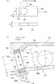
図6(a)に示すように、第1始動入賞口13a内には、始動入賞口内に入賞した遊技球を検出可能な2つのスイッチ(第1始動口スイッチ14aと第1入賞確認スイッチ14b)が設けられている。この実施例では、第1始動入賞口13a内で、第1始動口スイッチ14aと第1入賞確認スイッチ14bとが上下に配置されている(本例では、第1始動口スイッチ14aが上側に配置され、第1入賞確認スイッチ14bが下側に配置されている)。従って、この実施例では、第1始動入賞口13a内に入賞した遊技球は、遊技盤6の背面に導かれ、まず第1始動口スイッチ14aで検出され、次いで第1入賞確認スイッチ14bで検出される。
As shown in FIG. 6A, in the first start winning opening 13a, there are two switches (a first start opening switch 14a and a first winning confirmation switch 14b) capable of detecting a game ball won in the start winning opening. Is provided. In this embodiment, a first start opening switch 14a and a first winning confirmation switch 14b are arranged up and down in the first start winning opening 13a (in this example, the first start opening switch 14a is arranged on the upper side. The first winning confirmation switch 14b is arranged on the lower side). Therefore, in this embodiment, the game ball won in the first start winning opening 13a is guided to the back of the game board 6, first detected by the first start opening switch 14a, and then detected by the first winning confirmation switch 14b. Is done.
図6(b)に示すように、第2始動入賞口13b内には、始動入賞口内に入賞した遊技球を検出可能な2つのスイッチ(第2始動口スイッチ15aと第2入賞確認スイッチ15b)が設けられている。この実施例では、第2始動入賞口13b内で、第2始動口スイッチ15aと第2入賞確認スイッチ15bとが上下に配置されている(本例では、第2始動口スイッチ15aが上側に配置され、第2入賞確認スイッチ15bが下側に配置されている)。従って、この実施例では、第2始動入賞口13b内に入賞した遊技球は、遊技盤6の背面に導かれ、まず第2始動口スイッチ15aで検出され、次いで第2入賞確認スイッチ15bで検出される。
As shown in FIG. 6B, in the second start winning opening 13b, there are two switches (second start opening switch 15a and second winning confirmation switch 15b) that can detect the game balls won in the start winning opening. Is provided. In this embodiment, the second start opening switch 15a and the second winning confirmation switch 15b are arranged vertically in the second start winning opening 13b (in this example, the second start opening switch 15a is arranged on the upper side. The second winning confirmation switch 15b is arranged on the lower side). Therefore, in this embodiment, the game ball won in the second start winning opening 13b is guided to the back of the game board 6, first detected by the second start opening switch 15a, and then detected by the second winning confirmation switch 15b. Is done.
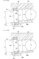
図6(c)に示すように、第1大入賞口23c内には、第1大入賞口23c内に入賞した遊技球を検出可能な2つのスイッチ(第1カウントスイッチ23aと第3入賞確認スイッチ23b)が設けられている。この実施例では、後述するように、第1大入賞口23c内で、第1カウントスイッチ23aと第3入賞確認スイッチ23bとが配置されている(本例では、第1カウントスイッチ23aが上側に配置され、第3入賞確認スイッチ23bが下側に配置されている)。従って、この実施例では、第1大入賞口23c内に入賞した遊技球は、遊技盤6の背面に導かれ、まず第1カウントスイッチ23aで検出され、次いで第3入賞確認スイッチ23bで検出される。
As shown in FIG. 6C, in the first grand prize opening 23c, there are two switches (a first count switch 23a and a third prize confirmation that can detect a game ball won in the first big prize opening 23c. A switch 23b) is provided. In this embodiment, as will be described later, a first count switch 23a and a third winning confirmation switch 23b are arranged in the first big winning opening 23c (in this example, the first count switch 23a is on the upper side). And a third winning confirmation switch 23b is arranged on the lower side). Therefore, in this embodiment, the game ball won in the first grand prize opening 23c is guided to the back of the game board 6, first detected by the first count switch 23a, and then detected by the third winning confirmation switch 23b. The
図6(d)に示すように、第2大入賞口24c内には、第2大入賞口24c内に入賞した遊技球を検出可能な2つのスイッチ(第2カウントスイッチ24aと第4入賞確認スイッチ24b)が設けられている。この実施例では、後述するように、第2大入賞口24c内で、第2カウントスイッチ24aと第4入賞確認スイッチ24bとが配置されている(本例では、第2カウントスイッチ24aが上側に配置され、第4入賞確認スイッチ24bが下側に配置されている)。従って、この実施例では、第2大入賞口24c内に入賞した遊技球は、遊技盤6の背面に導かれた後、第2カウントスイッチ24aで検出され、次いで第4入賞確認スイッチ24bで検出される。
As shown in FIG. 6D, in the second grand prize opening 24c, there are two switches (second count switch 24a and fourth prize confirmation that can detect a game ball won in the second big prize opening 24c. A switch 24b) is provided. In this embodiment, as will be described later, a second count switch 24a and a fourth winning confirmation switch 24b are arranged in the second big prize opening 24c (in this example, the second count switch 24a is on the upper side). And the fourth winning confirmation switch 24b is arranged on the lower side). Therefore, in this embodiment, the game ball won in the second grand prize opening 24c is guided to the back of the game board 6, detected by the second count switch 24a, and then detected by the fourth prize confirmation switch 24b. Is done.
また、第1始動口スイッチ14aと第1入賞確認スイッチ14b、第2始動口スイッチ15aと第2入賞確認スイッチ15b、第1カウントスイッチ23aと第3入賞確認スイッチ23b、第2カウントスイッチ24aと第4入賞確認スイッチ24bとして、それぞれ異なる検出方式のスイッチが用いられる。この実施例では、第1始動口スイッチ14a、第2始動口スイッチ15aおよび第1カウントスイッチ23a、第2カウントスイッチ24aとして近接スイッチを用い、第1入賞確認スイッチ14b、第2入賞確認スイッチ15b、第3入賞確認スイッチ23b、第4入賞確認スイッチ24bとしてフォトセンサを用いている。
Further, the first start opening switch 14a and the first winning confirmation switch 14b, the second starting opening switch 15a and the second winning confirmation switch 15b, the first count switch 23a and the third winning confirmation switch 23b, the second count switch 24a and the second count switch 24a. Different detection system switches are used as the 4-winning confirmation switch 24b. In this embodiment, proximity switches are used as the first start port switch 14a, the second start port switch 15a, the first count switch 23a, and the second count switch 24a, and the first winning confirmation switch 14b, the second winning confirmation switch 15b, Photosensors are used as the third winning confirmation switch 23b and the fourth winning confirmation switch 24b.
また、第1始動口スイッチ14aによって遊技球が検出されたことにもとづいて、第1特別図柄の変動表示が開始され、賞球払出が実行される。また、第2始動口スイッチ15aによって遊技球が検出されたことにもとづいて、第2特別図柄の変動表示が開始され、賞球払出が実行される。また、第1カウントスイッチ23a、第2カウントスイッチ24aによって遊技球が検出されたことにもとづいて、賞球払出が実行される。また、第1始動口スイッチ14aによる検出結果に加えて第1入賞確認スイッチ14bの検出結果にもとづいて異常入賞の発生の有無が判定され、異常入賞の発生を検出したことにもとづいてセキュリティ信号が外部出力される。また、第2始動口スイッチ15aによる検出結果に加えて第2入賞確認スイッチ15bの検出結果にもとづいて異常入賞の発生の有無が判定され、異常入賞の発生を検出したことにもとづいてセキュリティ信号が外部出力される。また、第1カウントスイッチ23aによる検出結果に加えて第3入賞確認スイッチ23bの検出結果にもとづいて異常入賞の発生の有無が判定され、異常入賞の発生を検出したことにもとづいてセキュリティ信号が外部出力される。また、第2カウントスイッチ24aによる検出結果に加えて第4入賞確認スイッチ24bの検出結果にもとづいて異常入賞の発生の有無が判定され、異常入賞の発生を検出したことにもとづいてセキュリティ信号が外部出力される。従って、第1入賞確認スイッチ14b、第2入賞確認スイッチ15b、第3入賞確認スイッチ23b、第4入賞確認スイッチ24bは、異常入賞の判定のみに用いられる。
Further, based on the detection of the game ball by the first start port switch 14a, the first special symbol variation display is started, and the prize ball payout is executed. Further, based on the fact that the game ball is detected by the second start port switch 15a, the display of the variation of the second special symbol is started, and a prize ball payout is executed. Also, a prize ball payout is executed based on the detection of the game ball by the first count switch 23a and the second count switch 24a. In addition to the detection result of the first start port switch 14a, whether or not an abnormal winning has occurred is determined based on the detection result of the first winning confirmation switch 14b, and the security signal is generated based on the detection of the abnormal winning. Output externally. In addition to the detection result of the second start opening switch 15a, the presence / absence of an abnormal winning is determined based on the detection result of the second winning confirmation switch 15b, and the security signal is generated based on the detection of the abnormal winning. Output externally. In addition to the detection result of the first count switch 23a, the presence / absence of occurrence of an abnormal winning is determined based on the detection result of the third winning confirmation switch 23b, and the security signal is generated based on the detection of the occurrence of the abnormal winning. Is output. In addition to the detection result of the second count switch 24a, the presence / absence of an abnormal winning is determined based on the detection result of the fourth winning confirmation switch 24b, and the security signal is generated based on the detection of the abnormal winning. Is output. Accordingly, the first winning confirmation switch 14b, the second winning confirmation switch 15b, the third winning confirmation switch 23b, and the fourth winning confirmation switch 24b are used only for determining an abnormal winning.
このように、第1始動口スイッチ14a、第2始動口スイッチ15a、第1カウントスイッチ23a、第2カウントスイッチ24aは近接スイッチを用いて構成し、第1〜第4入賞確認スイッチ14b,15b,23b,24bはフォトセンサを用いているが、第1始動口スイッチ14aと第1入賞確認スイッチ14b、第2始動口スイッチ15aと第2入賞確認スイッチ15b、第1カウントスイッチ23aと第3入賞確認スイッチ23b、第2カウントスイッチ24aと第4入賞確認スイッチ24bの検出方式はこの実施例で示したものにかぎらず、例えば、第1,2始動口スイッチ14a,15a及び第1,第2カウントスイッチ23a,24aと、第1〜4入賞確認スイッチ14b,15b,23b,24bとで異なる検出方式であれば、逆に第1,2始動口スイッチ14a,15a及び第1,第2カウントスイッチ23a,24aとしてフォトセンサを用い、第1〜4入賞確認スイッチ14b,15b,23b,24bとして近接スイッチを用いてもよい。この場合、フォトセンサである第1,2始動口スイッチ14a,15a及び第1カウントスイッチ23a、第2カウントスイッチ24aの検出結果にもとづいて特別図柄の変動表示や賞球払出処理が実行され、近接スイッチである第1〜4入賞確認スイッチ14b,15b,23b,24bの検出結果は、第1始動入賞口13a、第2始動入賞口13b、第1大入賞口23c、第2大入賞口24cの異常入賞の判定のみに用いられることになる。また、例えば、電磁式のスイッチである近接スイッチや光学式のフォトセンサに代えて、第1,2始動口スイッチ14a,15a及び第1,2カウントスイッチ23a,24aは第1〜4入賞確認スイッチ14b,15b,23b,24bとして、機械式のスイッチ(マイクロスイッチなど)を用いてもよい。
As described above, the first start port switch 14a, the second start port switch 15a, the first count switch 23a, and the second count switch 24a are configured using proximity switches, and the first to fourth winning check switches 14b, 15b, Although the photo sensors 23b and 24b are used, the first start opening switch 14a and the first winning confirmation switch 14b, the second starting opening switch 15a and the second winning confirmation switch 15b, the first count switch 23a and the third winning confirmation The detection methods of the switch 23b, the second count switch 24a, and the fourth winning confirmation switch 24b are not limited to those shown in this embodiment. For example, the first and second start port switches 14a and 15a and the first and second count switches 23a, 24a and the first to fourth winning confirmation switches 14b, 15b, 23b, 24b are different detection methods. Conversely, photosensors are used as the first and second start port switches 14a and 15a and the first and second count switches 23a and 24a, and proximity switches are used as the first to fourth winning confirmation switches 14b, 15b, 23b and 24b. May be. In this case, a special symbol variation display and a prize ball payout process are executed based on the detection results of the first and second start port switches 14a and 15a and the first count switch 23a and the second count switch 24a, which are photosensors. The detection results of the first to fourth winning confirmation switches 14b, 15b, 23b, and 24b, which are switches, are the results of the first starting winning port 13a, the second starting winning port 13b, the first major winning port 23c, and the second major winning port 24c. It will be used only for the determination of abnormal winnings. Also, for example, instead of a proximity switch or an optical photosensor that is an electromagnetic switch, the first and second start port switches 14a and 15a and the first and second count switches 23a and 24a are first to fourth winning confirmation switches. Mechanical switches (such as microswitches) may be used as 14b, 15b, 23b, and 24b.
また、この実施例では、特別図柄の変動表示や賞球払出処理の実行の契機となる第1,2始動口スイッチ14a,15a及び第1,2カウントスイッチ23a,24aは、異常入賞の判定に用いられる第1〜4入賞確認スイッチ14b,15b,23b,24bよりも上流側に設けられていたが、異常入賞の判定に用いられるスイッチの下流側に設けてもよい。
In this embodiment, the first and second start opening switches 14a and 15a and the first and second count switches 23a and 24a, which trigger the execution of the special symbol change display and the winning ball payout process, are used for determining an abnormal winning. Although the first to fourth winning confirmation switches 14b, 15b, 23b, and 24b used are provided on the upstream side, they may be provided on the downstream side of the switch used for determining the abnormal winning.
そして遊技制御用マイクロコンピュータ156は、第1始動口スイッチ14a(近接スイッチ)から入力した検出信号と第1入賞確認スイッチ14b(フォトセンサ)から入力した検出信号とにもとづいて、第1始動口スイッチ14aにて検出された遊技球数と第1入賞確認スイッチ14bにて検出された遊技球数との差が所定の閾値を超えたと判定すると、所定のエラーとして、第1始動入賞口13aへの異常入賞が発生したと判定する。また、第2始動口スイッチ15a(近接スイッチ)から入力した検出信号と第2入賞確認スイッチ15b(フォトセンサ)から入力した検出信号とにもとづいて、第2始動口スイッチ15aにて検出された遊技球数と第2入賞確認スイッチ15bにて検出された遊技球数との差が所定の閾値を超えたと判定すると、所定のエラーとして、第2始動入賞口13bへの異常入賞が発生したと判定する。
Then, the game control microcomputer 156 uses the first start port switch based on the detection signal input from the first start port switch 14a (proximity switch) and the detection signal input from the first winning confirmation switch 14b (photo sensor). If it is determined that the difference between the number of game balls detected at 14a and the number of game balls detected at the first winning confirmation switch 14b exceeds a predetermined threshold, a predetermined error is given to the first start winning opening 13a. It is determined that an abnormal winning has occurred. The game detected by the second start port switch 15a based on the detection signal input from the second start port switch 15a (proximity switch) and the detection signal input from the second winning confirmation switch 15b (photo sensor). If it is determined that the difference between the number of balls and the number of game balls detected by the second winning confirmation switch 15b exceeds a predetermined threshold value, it is determined that an abnormal winning to the second start winning port 13b has occurred as a predetermined error. To do.
第1カウントスイッチ23a(近接スイッチ)から入力した検出信号と第3入賞確認スイッチ23b(フォトセンサ)から入力した検出信号とにもとづいて、第1カウントスイッチ23aにて検出された遊技球数と第3入賞確認スイッチ23bにて検出された遊技球数との差が所定の閾値を超えたと判定すると、所定のエラーとして、第1大入賞口23cへの異常入賞が発生したと判定する。また、第2カウントスイッチ23a(近接スイッチ)から入力した検出信号と第4入賞確認スイッチ24b(フォトセンサ)から入力した検出信号とにもとづいて、第2カウントスイッチ24aにて検出された遊技球数と第4入賞確認スイッチ24bにて検出された遊技球数との差が所定の閾値を超えたと判定すると、所定のエラーとして、第2大入賞口24cへの異常入賞が発生したと判定する。
Based on the detection signal input from the first count switch 23a (proximity switch) and the detection signal input from the third winning confirmation switch 23b (photo sensor), the number of game balls detected by the first count switch 23a and the first If it is determined that the difference from the number of game balls detected by the 3-winning confirmation switch 23b exceeds a predetermined threshold, it is determined that an abnormal winning to the first grand prize opening 23c has occurred as a predetermined error. The number of game balls detected by the second count switch 24a based on the detection signal input from the second count switch 23a (proximity switch) and the detection signal input from the fourth winning confirmation switch 24b (photo sensor). And the number of game balls detected by the fourth winning confirmation switch 24b are determined to have exceeded a predetermined threshold, it is determined that an abnormal winning to the second big winning opening 24c has occurred as a predetermined error.
このように、第1始動口スイッチ14aと第1入賞確認スイッチ14b、第2始動口スイッチ15aと第2入賞確認スイッチ15b、第1カウントスイッチ23aと第3入賞確認スイッチ23b、第2カウントスイッチ24aと第4入賞確認スイッチ24bと、を互いに異なる検出方式のセンサ(本例では、近接スイッチとフォトセンサ)により構成していることで、例えば電磁波などを用いて第1始動入賞口13a、第2始動入賞口13b、第1大入賞口23c、第2大入賞口24cへの入賞数が実際の入賞数よりも多くなるように認識させるような不正行為が行われた場合に、近接スイッチにて検出された遊技球数とフォトスイッチにて検出された遊技球数とに差が生じ、遊技制御用マイクロコンピュータ156はこの差球数が所定の閾値(例えば、本実施例では15)を超えた場合に異常入賞が発生したと判定するため、確実な不正行為対策を講ずることができる。
As described above, the first start opening switch 14a and the first winning confirmation switch 14b, the second starting opening switch 15a and the second winning confirmation switch 15b, the first count switch 23a, the third winning confirmation switch 23b, and the second count switch 24a. And the fourth winning confirmation switch 24b are configured by sensors of different detection methods (in this example, a proximity switch and a photo sensor), for example, using the electromagnetic wave or the like, the first start winning award 13a, When a fraudulent action is performed to make the recognition so that the number of winnings at the start winning port 13b, the first grand winning port 23c, and the second large winning port 24c is larger than the actual winning number, the proximity switch is used. There is a difference between the number of game balls detected and the number of game balls detected by the photoswitch, and the game control microcomputer 156 determines that the difference ball number is a predetermined threshold value. (E.g., 15 in this embodiment) for determining that abnormal winning if it exceeds occurs, it is possible to take reliable fraud measures.
遊技領域7の左右周辺には、遊技中に点滅表示される装飾LED25aを有する装飾部材25L,25Rが設けられ、下部には、入賞しなかった遊技球を吸収するアウト口26がある。また、遊技領域7の外側の左右上下部には、効果音を発する4つのスピーカ27が設けられている。遊技領域7の外周には、天枠ランプ28a、左枠ランプ28bおよび右枠ランプ28cが設けられている。天枠ランプ28a、左枠ランプ28bおよび右枠ランプ28cおよび装飾LED25aは、遊技機に設けられている装飾発光体の一例である。
Decorative members 25L and 25R having decorative LEDs 25a blinking and displayed during the game are provided around the left and right sides of the game area 7, and an out port 26 for absorbing a game ball that has not won a prize is provided below. In addition, four speakers 27 that emit sound effects are provided on the left, right, top, and bottom of the outside of the game area 7. On the outer periphery of the game area 7, a top frame lamp 28a, a left frame lamp 28b, and a right frame lamp 28c are provided. The top frame lamp 28a, the left frame lamp 28b, the right frame lamp 28c, and the decoration LED 25a are examples of a decoration light emitter provided in the gaming machine.
また、演出表示装置9の周囲には、表示画面の周囲を装飾するセンター枠飾り11(図1中網点領域)が設けられており、このセンター枠飾り11の上部には、前述した第2特別可変入賞球装置24が設けられているとともに、導光板351の端面に光を出射するセンター枠飾りLED62a〜62d(図3参照)が設けられている。
Further, a center frame ornament 11 (halftone dot region in FIG. 1) for decorating the periphery of the display screen is provided around the effect display device 9, and the second frame described above is provided above the center frame ornament 11. A special variable winning ball apparatus 24 is provided, and center frame decoration LEDs 62 a to 62 d (see FIG. 3) that emit light to the end face of the light guide plate 351 are provided.
図1では、図示を省略しているが、左枠ランプ28bの近傍に、賞球払出中に点灯する賞球ランプが設けられ、天枠ランプ28aの近傍に、補給球が切れたときに点灯する球切れランプ(図示略)が設けられている。尚、賞球ランプおよび球切れランプは、賞球の払出中である場合や球切れが検出された場合に、演出制御基板に搭載された演出制御用マイクロコンピュータによって点灯制御される。さらに、特に図示はしないが、プリペイドカードが挿入されることによって球貸しを可能にするプリペイドカードユニット(以下、「カードユニット」という。)50が、パチンコ遊技機1に隣接して設置されている。
Although not shown in FIG. 1, a prize ball lamp that is turned on during the payout of a prize ball is provided in the vicinity of the left frame lamp 28b, and lights up when the supply ball is cut in the vicinity of the top frame lamp 28a. A ball break lamp (not shown) is provided. Note that the award ball lamp and the out-of-ball lamp are controlled to be turned on by an effect control microcomputer mounted on the effect control board when the award ball is being paid out or when a ball out is detected. Further, although not shown in particular, a prepaid card unit (hereinafter referred to as “card unit”) 50 that enables lending a ball by inserting a prepaid card is installed adjacent to the pachinko gaming machine 1. .
遊技者の操作により、打球発射装置65(図2参照)から発射された遊技球は、発射球案内通路(図示略)を通って遊技領域7に入り、その後、遊技領域7を下りてくる。遊技球が第1始動入賞口13aに入り第1始動口スイッチ14aで検出されると、第1特別図柄の可変表示を開始できる状態であれば(例えば、特別図柄の可変表示が終了し、第1の開始条件が成立したこと)、第1特別図柄表示器8aにおいて第1特別図柄の可変表示(変動)が開始されるとともに、演出表示装置9において演出図柄(飾り図柄)の可変表示が開始される。すなわち、第1特別図柄および演出図柄の可変表示は、第1始動入賞口13aへの入賞に対応する。第1特別図柄の可変表示を開始できる状態でなければ、第1保留記憶数が上限値に達していないことを条件として、第1保留記憶数を1増やす。
A game ball launched from the hitting ball launching device 65 (see FIG. 2) by the player's operation enters the game area 7 through the shot ball guide passage (not shown), and then descends the game area 7. When the game ball enters the first start winning port 13a and is detected by the first start port switch 14a, if the variable display of the first special symbol can be started (for example, the variable display of the special symbol ends, 1), the first special symbol display 8a starts variable display (variation) of the first special symbol, and the effect display device 9 starts variable display of the effect symbol (decoration symbol). Is done. In other words, the variable display of the first special symbol and the effect symbol corresponds to winning in the first start winning opening 13a. If the variable display of the first special symbol cannot be started, the first reserved memory number is increased by 1 on the condition that the first reserved memory number has not reached the upper limit value.
遊技球が第2始動入賞口13bに入り第2始動口スイッチ15aで検出されると、第2特別図柄の可変表示を開始できる状態であれば(例えば、特別図柄の可変表示が終了し、第2の開始条件が成立したこと)、第2特別図柄表示器8bにおいて第2特別図柄の可変表示(変動)が開始されるとともに、演出表示装置9において演出図柄(飾り図柄)の可変表示が開始される。すなわち、第2特別図柄および演出図柄の可変表示は、第2始動入賞口13bへの入賞に対応する。第2特別図柄の可変表示を開始できる状態でなければ、第2保留記憶数が上限値に達していないことを条件として、第2保留記憶数を1増やす。
When the game ball enters the second start winning port 13b and is detected by the second start port switch 15a, if the variable display of the second special symbol can be started (for example, the special symbol variable display ends, 2), the second special symbol display 8b starts variable display (variation) of the second special symbol, and the effect display device 9 starts variable display of the effect symbol (decoration symbol). Is done. That is, the variable display of the second special symbol and the effect symbol corresponds to winning in the second start winning opening 13b. If the variable display of the second special symbol cannot be started, the second reserved memory number is increased by 1 on condition that the second reserved memory number has not reached the upper limit value.
第1特別図柄表示器8aにおける第1特別図柄の可変表示及び第2特別図柄表示器8bにおける第2特別図柄の可変表示は、一定時間が経過したときに停止する。停止時の特別図柄(停止図柄)が大当り図柄(特定表示結果)であると「大当り」となり、停止時の特別図柄(停止図柄)が大当り図柄とは異なる所定の小当り図柄(所定表示結果)であると「小当り」となり、停止時の特別図柄(停止図柄)が大当り図柄及び小当り図柄とは異なる特別図柄が停止表示されれば「ハズレ」となる。
The variable display of the first special symbol on the first special symbol display 8a and the variable display of the second special symbol on the second special symbol display 8b are stopped when a certain time has elapsed. If the special symbol (stop symbol) at the time of stoppage is a big hit symbol (specific display result), it will be “big hit”, and the special symbol (stop symbol) at the time of stop will be different from the big hit symbol (predetermined display result) Is “small hit”, and if the special symbol at the time of stoppage (stop symbol) is stopped and displayed, a special symbol different from the big hit symbol and the small hit symbol is “lost”.
特図ゲームでの可変表示結果が「大当り」になった後には、遊技者にとって有利なラウンド(「ラウンド遊技」ともいう)を所定回数実行する特定遊技状態としての大当り遊技状態に制御される。また、特図ゲームでの可変表示結果が「小当り」になった後には、大当り遊技状態とは異なる小当り遊技状態に制御される。
After the variable display result in the special figure game becomes “big hit”, the game is controlled to the big hit gaming state as a specific gaming state in which a round advantageous to the player (also referred to as “round game”) is executed a predetermined number of times. Further, after the variable display result in the special figure game becomes “small hit”, the game is controlled to the small hit game state different from the big hit game state.
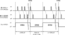
この実施例では、特図ゲームにおける確定特別図柄が「非確変」または「確変A」に対応する大当り図柄が停止表示された場合には、多ラウンド特定遊技状態としての第1大当り状態(15ラウンド大当り状態)に移行する。大当り遊技状態(通常15ラウンド大当り状態)では、第1特別可変入賞球装置23の第1大入賞口23cを、第1期間となる所定期間(例えば29.5秒間)あるいは所定個数(例えば8個)の入賞球が発生するまでの期間にて開放状態とすることにより、第1特別可変入賞球装置23を遊技者にとって有利な第1状態(開放状態)に変化させるラウンドが実行される。こうしてラウンドの実行中に第1大入賞口23cを開放状態とした第1特別可変入賞球装置23は、遊技盤6の表面を落下する遊技球を受け止め、その後に第1大入賞口23cを閉鎖状態とすることにより、第1特別可変入賞球装置23を遊技者にとって不利な第2状態(閉鎖状態)に変化させて、1回のラウンドを終了させる。15ラウンド大当り状態では、第1大入賞口23cの開放サイクルであるラウンドの実行回数が、第1ラウンド数(例えば「15」)となる。ラウンドの実行回数が「15」となる15ラウンド大当り状態における遊技は、15回開放遊技とも称される。このような15ラウンド大当り状態では、第1大入賞口23cに遊技球が入賞するたびに15個の出玉(賞球)が得られる。尚、15ラウンド大当り状態は、第1特定遊技状態ともいう。
In this embodiment, when the big win symbol corresponding to “non-probability change” or “probability change A” in the special figure game is stopped and displayed, the first big win state (15 rounds) as the multi-round specific game state is displayed. (Big hit state). In the big hit gaming state (usually 15 round big hit state), the first big winning opening 23c of the first special variable winning ball apparatus 23 is set to a predetermined period (for example, 29.5 seconds) or a predetermined number (for example, eight). ), The first special variable winning ball apparatus 23 is changed to the first state (open state) advantageous to the player, so that the round is executed. In this way, the first special variable winning ball apparatus 23 that opens the first big winning opening 23c during the round receives the game ball falling on the surface of the game board 6, and then closes the first big winning opening 23c. By setting the state, the first special variable winning ball apparatus 23 is changed to the second state (closed state) disadvantageous to the player, and one round is completed. In the 15 round big hit state, the number of executions of the round which is the opening cycle of the first big winning opening 23c becomes the first round number (for example, “15”). A game in the 15 round big hit state in which the number of round executions is “15” is also referred to as a 15-time open game. In such a 15 round big hit state, every time a game ball wins the first big winning opening 23c, 15 balls (prize balls) are obtained. The 15-round big hit state is also referred to as a first specific game state.
特図ゲームにおける確定特別図柄として「確変B」に対応する大当り図柄が停止表示された場合には、多ラウンド特定遊技状態としての第2大当り状態(高速15ラウンド大当り状態)に移行する。第2大当り状態では、第2特別可変入賞球装置24の第2大入賞口24cを、第1大当り状態における第1期間よりも短い第2期間(例えば0.5秒間)あるいは所定個数(例えば3個)の入賞球が発生するまでの期間にて開放状態とすることにより、第2特別可変入賞球装置24を遊技者にとって有利な第1状態(開放状態)に変化させるラウンドが実行される。こうしてラウンドの実行中に第2大入賞口24cを開放状態とした第2特別可変入賞球装置24は、遊技盤6の表面を落下する遊技球を受け止め、その後に第2大入賞口24cを閉止状態とすることにより、第2特別可変入賞球装置24を遊技者にとって不利な第2状態(閉止状態)に変化させて、1回のラウンドを終了させる。第2大当り状態では、第2大入賞口24cの開放サイクルであるラウンドの実行回数が、第2ラウンド数(例えば「15」)となる。
When the big hit symbol corresponding to “probability change B” is stopped and displayed as the confirmed special symbol in the special figure game, the state shifts to the second big hit state (high-speed 15 round big hit state) as the multi-round specific gaming state. In the second big hit state, the second special winning opening 24c of the second special variable winning ball device 24 is set to a second period (for example, 0.5 seconds) shorter than the first period in the first big hit state or a predetermined number (for example, 3). A round in which the second special variable winning ball apparatus 24 is changed to the first state (open state) advantageous to the player is executed by setting the open state in the period until the number of winning balls is generated. In this way, the second special variable winning ball device 24 that has opened the second big prize opening 24c during execution of the round receives the game ball falling on the surface of the game board 6, and then closes the second big prize opening 24c. By setting the state, the second special variable winning ball apparatus 24 is changed to the second state (closed state) disadvantageous to the player, and one round is completed. In the second big hit state, the number of executions of the round which is the opening cycle of the second big winning opening 24c is the second round number (for example, “15”).
このような第2大当り状態では、第2大入賞口24cに遊技球が入賞すれば15個の出玉(賞球)が得られるが、第2大入賞口24cの開放期間が第2期間(0.5秒間)であって、非常に短い。そのため、第2大当り状態は実質的には出玉(賞球)が得られない大当り遊技状態である。尚、第2大当り状態は第2特定遊技状態ともいう。また、第2大当り状態は、第1大当り状態に比べてラウンドの実行回数が少ないものであってもよい。すなわち、第2大当り状態は、各ラウンドで第2大入賞口24cを開放状態に変化させる期間が第1大当り状態における第1期間よりも短い第2期間となることと、ラウンドの実行回数が第1大当り状態における第1ラウンド数よりも少ない第2ラウンド数となることのうち、少なくともいずれか一方となるものであってもよい。
In such a second big hit state, 15 game balls (prize balls) are obtained if a game ball wins the second big winning opening 24c, but the opening period of the second big winning opening 24c is the second period ( 0.5 seconds) and very short. For this reason, the second big hit state is a big hit gaming state in which a ball (prize ball) cannot be obtained substantially. The second big hit state is also called a second specific game state. Further, the second big hit state may be one in which the number of round executions is smaller than that in the first big hit state. That is, in the second big hit state, the period in which the second big prize opening 24c is changed to the open state in each round is a second period shorter than the first period in the first big hit state, and the number of executions of the round is the first. It may be at least one of the second round numbers less than the first round number in the big hit state.
また、「非確変」に対応する大当り図柄が特図ゲームにおける確定特別図柄として停止表示されたことに基づき第1大当り状態が終了した後には、特別遊技状態の1つとして、通常状態に比べて特図ゲームにおける特別図柄の可変表示時間(特図変動時間)が短縮される時間短縮制御(時短制御)が行われる時短状態に制御される。ここで、通常状態とは、大当り遊技状態等の特定遊技状態や確変状態及び時短状態とは異なる遊技状態としての通常遊技状態であり、パチンコ遊技機1の初期設定状態(例えばシステムリセットが行われた場合のように、電源投入後に初期化処理を実行した状態)と同一の制御が行われる。時短状態は、所定回数(例えば100回)の特図ゲームが実行されることと、可変表示結果が「大当り」となることのうち、いずれかの条件が先に成立したときに、終了すればよい。このように「非確変」に対応する大当り図柄特別図柄のように、特図ゲームにおける確定特別図柄として停止表示されたことに基づく第1大当り状態が終了した後に時短状態に制御される大当り図柄は、非確変大当り図柄(「通常大当り図柄」ともいう)と称される。また、大当り図柄のうち非確変大当り図柄が停止表示されて可変表示結果が「大当り」となることは、「非確変大当り」(「通常大当り」ともいう)と称される。
In addition, after the first jackpot state is ended based on the fact that the jackpot symbol corresponding to “non-probable change” is stopped and displayed as a confirmed special symbol in the special figure game, it is compared with the normal state as one of the special gaming states. The time is controlled to be in a time-short state in which time-shortening control (short-time control) is performed in which the variable symbol display time (special-figure variation time) is shortened in the special game. Here, the normal state is a normal game state as a game state different from a specific game state such as a big hit game state, a probability change state, and a short time state, and an initial setting state of the pachinko gaming machine 1 (for example, a system reset is performed). As in the case where the initialization process is performed after the power is turned on, the same control is performed. If the time-short state is terminated when any of the conditions of the special game is executed a predetermined number of times (for example, 100 times) and the variable display result is “big hit” is satisfied first, Good. Thus, like the big hit symbol special symbol corresponding to “non-probable change”, the big hit symbol controlled to the short-time state after the first big hit state based on being stopped and displayed as the confirmed special symbol in the special symbol game is This is called a non-probable big hit symbol (also referred to as “normal big hit symbol”). Further, the fact that the non-probable variable big hit symbol among the big hit symbols is stopped and displayed and the variable display result becomes “big hit” is called “non-probable big hit” (also referred to as “normal big hit”).
「確変A」に対応する大当り図柄が特図ゲームにおける確定特別図柄として停止表示されたことに基づき第1大当り状態が終了した後や、確変状態において「確変B」に対応する大当り図柄が特図ゲームにおける確定特別図柄として停止表示されたことに基づき第2大当り状態が終了した後には、時短状態とは異なる特別遊技状態の1つとして、例えば通常状態に比べて特図変動時間が短縮される時短制御とともに、継続して確率変動制御(確変制御)が行われる確変状態(高確率状態)に制御される。この確変状態では、各特図ゲームや飾り図柄の可変表示において、可変表示結果が「大当り」となって更に大当り遊技状態に制御される確率が、通常状態や時短状態よりも高くなるように向上する。このような確変状態は、特図ゲームの実行回数にかかわりなく、次に可変表示結果が「大当り」となるまで継続する。
The jackpot symbol corresponding to “probability variation B” is displayed after the first big hit state is ended based on the fact that the jackpot symbol corresponding to “probability variation A” is stopped and displayed as a confirmed special symbol in the special symbol game. After the second big hit state is ended based on the fact that it is stopped and displayed as a confirmed special symbol in the game, the special figure variation time is shortened as one of the special game states different from the short-time state, for example, compared with the normal state. Along with the time-shortening control, the state is controlled to a probability variation state (high probability state) in which probability variation control (probability variation control) is continuously performed. In this probabilistic state, the variable display result of each special figure game and decorative design is improved so that the probability that the variable display result will be “big hit” and further controlled to the big hit gaming state will be higher than in the normal state and the short-time state. To do. Such a probability change state continues until the next variable display result is a “big hit”, regardless of the number of executions of the special game.
こうした「確変A」に対応する大当り図柄のように、特図ゲームにおける確定特別図柄として停止表示されたことに基づく第1大当り状態が終了した後に確変状態に制御される大当り図柄は、確変大当り図柄と称される。また、「確変B」に対応する大当り図柄のように、特図ゲームにおける確定特別図柄として停止表示されたことに基づく大当り遊技状態が終了した後に確変状態に制御される大当り図柄は、突確大当り図柄と称される。また、大当り図柄のうち確変大当り図柄が停止表示されて可変表示結果が「大当り」となることは、「確変大当り」と称される。突確大当り図柄が停止表示されて可変表示結果が「大当り」となることは、「突確大当り」(「突確大当り」ともいう)と称される。尚、これら大当り図柄は任意であり、例えば、遊技者に大当り図柄であることや、大当り種別を認識されないようにするために、大当り図柄を数字とせずに予め定められた記号等にしてもよい。
Like the jackpot symbol corresponding to such “probability change A”, the jackpot symbol controlled to the probability change state after the first jackpot state based on being stopped and displayed as the confirmed special symbol in the special figure game is the probability change jackpot symbol. It is called. In addition, like the jackpot symbol corresponding to “probability change B”, the jackpot symbol controlled to the probability change state after the jackpot game state based on being stopped and displayed as the confirmed special symbol in the special figure game is the sudden hit bonus symbol. It is called. In addition, the probability variation big hit symbol out of the big hit symbol is stopped and displayed and the variable display result becomes “big hit” is called “probable big hit”. The fact that the sudden hit symbol is stopped and displayed and the variable display result is “big hit” is called “surprise big hit” (also referred to as “surprise big hit”). These jackpot symbols are arbitrary. For example, in order to prevent the player from recognizing the jackpot type, the jackpot symbol may not be a number but may be a predetermined symbol or the like. .
「小当り」に対応する特別図柄が特図ゲームにおける確定特別図柄として停止表示された後には、小当り遊技状態に制御される。この小当り遊技状態では、第2大当り状態と同様に第2特別可変入賞球装置24において第2大入賞口24cを遊技者にとって有利な第1状態(開放状態)に変化させる可変入賞動作が行われる。すなわち、小当り遊技状態では、例えば第2特別可変入賞球装置24を第2期間にわたり第1状態(開放状態)とする動作が、第2回数{第2ラウンド数に等しい実行回数(本例では、15回)}に達するまで繰り返し実行される。尚、小当り遊技状態では、第2大当り状態と同様に、第2特別可変入賞球装置24を第1状態とする期間が第2期間となることと、第1状態とする動作の実行回数が第2回数となることのうち、少なくともいずれか一方が行われるように制御されればよい。小当り遊技状態が終了した後には、遊技状態の変更が行われず、可変表示結果が「小当り」となる以前の遊技状態に継続して制御されることになる。ただし、可変表示結果が「小当り」となる特図ゲームが実行されたときに、特別遊技状態における特図ゲームの実行回数が所定回数に達していれば、小当り遊技状態の終了後には、特別遊技状態が終了して通常状態となることがある。可変入賞動作により第2特別可変入賞球装置24を第1状態とする回数が「15」である小当り遊技状態における遊技は、第2大当り状態における遊技と同様に、15回開放遊技とも称される。尚、第2大当り状態における各ラウンドで第2特別可変入賞球装置24とは別個に設けられた入賞球装置を第1状態に変化させる場合には、小当り遊技状態でも、第2大当り状態と同様の態様で、その入賞球装置を第1状態に変化させるようにすればよい。
After the special symbol corresponding to “small hit” is stopped and displayed as the confirmed special symbol in the special symbol game, the small hit game state is controlled. In this small hit game state, similarly to the second big hit state, in the second special variable winning ball apparatus 24, a variable winning operation for changing the second big winning port 24c to the first state (open state) advantageous to the player is performed. Is called. That is, in the small hit gaming state, for example, the operation of setting the second special variable winning ball device 24 to the first state (open state) for the second period is the second number {the number of executions equal to the second number of rounds (in this example, , 15 times)}. In the small hit gaming state, as in the second big hit state, the period during which the second special variable winning ball device 24 is in the first state is the second period, and the number of executions of the operation in the first state is Control may be made so that at least one of the second times is performed. After the small hit gaming state ends, the gaming state is not changed, and the game state before the variable display result becomes “small hit” is continuously controlled. However, if the number of executions of the special figure game in the special gaming state has reached the predetermined number when the special figure game with the variable display result “small hit” is executed, after the end of the small hit gaming state, The special gaming state may end and return to the normal state. A game in the small hit game state in which the number of times that the second special variable winning ball apparatus 24 is set to the first state by the variable winning operation is “15” is also referred to as a 15-time open game, similar to the game in the second big win state. The When the winning ball device provided separately from the second special variable winning ball device 24 in each round in the second big hit state is changed to the first state, even in the small hit gaming state, the second big hit state is changed. In the same manner, the winning ball apparatus may be changed to the first state.
確変状態や時短状態では、普通図柄表示器10による普図ゲームにおける普通図柄の変動時間(普図変動時間)を通常状態のときよりも短くする制御や、各回の普図ゲームで普通図柄の可変表示結果が「普図当り」となる確率を通常状態のときよりも向上させる制御、可変表示結果が「普図当り」となったことに基づく可変入賞球装置15における可動翼片の傾動制御を行う傾動制御時間を通常状態のときよりも長くする制御、その傾動回数を通常状態のときよりも増加させる制御といった、遊技球が第2始動入賞口13bを通過(進入)しやすくして第2始動条件が成立する可能性を高めることで遊技者にとって有利となる制御が行われる。尚、確変状態や時短状態では、これらの制御のいずれか1つが行われるようにしてもよいし、複数の制御が組合せられて行われるようにしてもよい。このように、確変状態や時短状態において第2始動入賞口13bに遊技球が進入しやすくして遊技者にとって有利となる制御は、高開放制御ともいう。高開放制御が行われることにより、第2始動入賞口13bは、高開放制御が行われていないときよりも拡大開放状態となる頻度が高められる。これにより、第2特別図柄表示器8bにおける第2特図を用いた特図ゲームを実行するための第2始動条件が成立しやすくなり、特図ゲームが頻繁に実行可能となることで、次に可変表示結果が「大当り」となるまでの時間が短縮される。したがって、確変状態や時短状態では、通常状態に比べて大当り遊技状態となりやすくなる。高開放制御が実行可能となる期間は、高開放制御期間ともいい、この期間は、パチンコ遊技機1における遊技状態が確変状態と時短状態のいずれかに制御されている期間と同一であればよい。また、高開放制御期間であるときには、遊技状態が高ベース中であるともいう。これに対して、高開放制御期間でないときには、遊技状態が低ベース中であるともいう。この実施例における時短状態は、低確高ベース状態とも称される遊技状態であり、通常状態は、低確低ベース状態とも称される遊技状態であり、高開放制御期間ではない確変状態である潜伏確変状態は高確低ベース状態とも称される遊技状態である。
In the probabilistic state and the short time state, the normal symbol display unit 10 controls the normal symbol in the normal symbol game so that the variation time of the normal symbol (ordinary symbol variation time) is shorter than that in the normal state. Control to improve the probability that the display result is “per normal figure” than in the normal state, and tilt control of the movable blade piece in the variable winning ball apparatus 15 based on the fact that the variable display result is “per normal figure”. The game ball can easily pass (enter) the second start winning opening 13b, such as control for making the tilt control time to be performed longer than that in the normal state, and control for increasing the number of tilts than in the normal state. Control that is advantageous to the player is performed by increasing the possibility that the start condition is satisfied. It should be noted that any one of these controls may be performed in the probability variation state or the short time state, or a plurality of controls may be performed in combination. As described above, the control that facilitates the entry of the game ball into the second start winning opening 13b in the probability change state or the short time state is also referred to as high release control. When the high opening control is performed, the frequency at which the second start winning opening 13b is in the expanded opening state is higher than when the high opening control is not performed. As a result, the second start condition for executing the special figure game using the second special figure in the second special symbol display 8b is easily established, and the special figure game can be executed frequently. In addition, the time until the variable display result becomes “big hit” is shortened. Therefore, in the probability variation state and the short time state, it becomes easier to enter the big hit gaming state than in the normal state. The period during which the high opening control can be executed is also referred to as a high opening control period, and this period may be the same as the period during which the gaming state in the pachinko gaming machine 1 is controlled to either the certain change state or the short-time state. . Further, it is also said that the gaming state is in the high base during the high opening control period. On the other hand, when it is not the high opening control period, it is said that the gaming state is in the low base. The short-time state in this embodiment is a gaming state also referred to as a low-probability high-base state, and the normal state is a gaming state also referred to as a low-probability low-base state, which is a probabilistic state that is not a high release control period. The latent probability changing state is a gaming state also called a high probability low base state.
また、この実施例では、通常状態において「確変B」に対応する「突確大当り」となったことに基づく第2大当り状態の終了後には、確変制御のみが行われて時短制御や高開放制御が行われない第2確変制御(潜伏確変状態)へ移行する。また、確変状態において「突確大当り」となったことに基づく第2大当り状態の終了後には、確変制御とともに時短制御や高開放制御が行われる第1確変状態へ移行する。
In this embodiment, after the end of the second big hit state based on the “probability big hit” corresponding to “probability change B” in the normal state, only the probability change control is performed, and the time-shortening control and the high opening control are performed. The process proceeds to the second probability variation control (latent probability variation state) that is not performed. Further, after the end of the second big hit state based on the fact that the “probable big hit” is made in the probability change state, the state shifts to the first probability change state where the time-shortening control and the high opening control are performed together with the probability change control.
このように確変状態のうちには、確変制御とともに時短制御や高開放制御が行われるものの他に、確変制御のみが行われて時短制御や高開放制御が行われないもの(潜伏確変)が含まれていてもよい。また、例えば、特図ゲームにける可変表示結果が「確変大当り」となったことに基づく第1大当り状態の終了後には、確変制御とともに時短制御や高開放制御が行われる第1確変状態(高確高ベース状態ともいう)に制御され、その後、特図表示結果が「大当り」となることなく、特図ゲームの実行回数が所定回数(例えば70回)に達したときには、確変制御は継続して行われるものの、時短制御や高開放制御が終了して行われなくなる第2確変状態(高確低ベース状態ともいう)に制御されるようにしてもよい。
As described above, the probability variation state includes not only the time variation control and the high release control are performed together with the probability variation control but also the probability variation control only and the time reduction control and the high release control are not performed (latency probability variation). It may be. In addition, for example, after the first big hit state based on the fact that the variable display result in the special figure game is “probable big hit”, the first positive change state (high-speed control and high-open control are performed together with the positive change control (high When the number of executions of the special figure game reaches a predetermined number of times (for example, 70 times) without the special figure display result being “big hit”, the probability variation control is continued. However, the control may be performed in a second certain change state (also referred to as a highly accurate low base state) that is not performed after the time-shortening control or the high opening control is finished.
また、この実施例では、確変状態であるときに特図ゲームにおける可変表示結果が「突確大当り」となったことに基づく第2大当り状態の終了後には第2確変状態(潜伏確変状態)へと移行するようになっていたが、確変状態だけでなく、時短状態であるときに特図ゲームにおける可変表示結果が「突確大当り」となったことに基づく第2大当り状態の終了後にも第1確変状態へと移行するようにしてもよい。あるいは、「確変大当り」に基づく第1大当り状態の終了後には、再び特図表示結果が「大当り」となるまで第1確変状態に制御される一方、「突確大当り」に基づく第2大当り状態の終了後には、第1確変状態に移行して、特図表示結果が「大当り」となることなく特図ゲームの実行回数が所定回数に達したときに第2確変状態へと移行するようにしてもよい。時短制御と高開放制御は、それらの開始と終了が同時に(連動して)行われる一方で、確変制御の開始と終了は、時短制御や高開放制御の開始や終了と必ずしも連動するものでなくてもよい。
Further, in this embodiment, after the second big hit state is ended based on the fact that the variable display result in the special game is “surprise big hit” in the probability changing state, the second probability changing state (latent probability changing state) is reached. Although the transition was made, not only the probability change state but also the first probability change even after the end of the second big hit state based on the fact that the variable display result in the special game is “abrupt big hit” when in the short time state You may make it transfer to a state. Alternatively, after the first big hit state based on the “probable big hit” is finished, it is controlled to the first positive change state until the special figure display result becomes “big hit” again, while the second big hit state based on the “surprise big hit” is controlled. After the completion, the process shifts to the first certain change state, and when the number of executions of the special figure game reaches a predetermined number without causing the special figure display result to be “big hit”, the second certain change state is entered. Also good. While the short-time control and the high-open control are started and ended simultaneously (interlocked), the start and end of the probability variation control is not necessarily linked to the start and end of the short-time control and high-open control. May be.
演出表示装置9に設けられた「左」、「中」、「右」の飾り図柄表示エリアでは、第1特別図柄表示器8aにおける第1特図を用いた特図ゲームと、第2特別図柄表示器8bにおける第2特図を用いた特図ゲームとのうち、いずれかの特図ゲームが開始されることに対応して、飾り図柄の可変表示(変動表示)が開始される。そして、飾り図柄の可変表示が開始されてから「左」、「中」、「右」の各飾り図柄表示エリアにおける確定飾り図柄の停止表示により可変表示が終了するまでの期間では、飾り図柄の可変表示状態が所定のリーチ状態となることがある。ここで、リーチ状態とは、演出表示装置9の表示領域にて仮停止表示された飾り図柄が大当り組合せの一部を構成しているときに未だ仮停止表示もされていない飾り図柄(「リーチ変動図柄」ともいう)については変動が継続している表示状態、あるいは、全部又は一部の飾り図柄が大当り組合せの全部又は一部を構成しながら同期して変動している表示状態のことである。具体的には、「左」、「中」、「右」の飾り図柄表示エリアにおける一部(例えば「左」及び「右」の飾り図柄表示エリアなど)では予め定められた大当り組合せを構成する飾り図柄(例えば「7」の英数字を示す飾り図柄)が仮停止表示されているときに未だ仮停止表示もしていない残りの飾り図柄表示エリア(例えば「中」の飾り図柄表示エリアなど)では飾り図柄が変動している表示状態、あるいは、「左」、「中」、「右」の飾り図柄表示エリアにおける全部又は一部で飾り図柄が大当り組合せの全部又は一部を構成しながら同期して変動している表示状態である。
In the “left”, “middle”, and “right” decorative symbol display areas provided in the effect display device 9, the special symbol game using the first special symbol and the second special symbol in the first special symbol display 8a. Corresponding to the start of one of the special figure games using the second special figure on the display unit 8b, the variable display (variation display) of the decorative symbols is started. In the period from the start of variable display of decorative symbols to the end of variable display due to the stop display of the fixed decorative symbols in the “left”, “middle”, and “right” decorative symbol display areas, The variable display state may be a predetermined reach state. Here, the reach state means a decorative symbol (“reach” which is not yet temporarily stopped when the decorative symbol temporarily stopped displayed in the display area of the effect display device 9 forms a part of the jackpot combination. "Varying symbol") is a display state in which the variation continues, or a display state in which all or part of the decorative symbols change synchronously while constituting all or part of the jackpot combination is there. Specifically, a part of the “left”, “middle”, and “right” decorative symbol display areas (for example, “left” and “right” decorative symbol display areas) constitutes a predetermined jackpot combination. In a remaining decorative symbol display area (for example, a “medium” decorative symbol display area, etc.) that has not yet been temporarily stopped when a decorative symbol (for example, a decorative symbol indicating the alphanumeric character “7”) is temporarily stopped. The display state in which the decorative symbols are fluctuating, or all or part of the “left”, “middle”, and “right” decorative symbol display areas are synchronized while the decorative symbols constitute all or part of the jackpot combination. The display state is fluctuating.
次に、パチンコ遊技機1の背面の構造について図2を参照して説明する。図2は、遊技機を背面から見た背面図である。図2に示すように、パチンコ遊技機1の背面側では、演出表示装置9を制御する演出制御用マイクロコンピュータが搭載された演出制御基板80を含む変動表示制御ユニット49、遊技制御用マイクロコンピュータ等が搭載された遊技制御基板(主基板)31、音声制御基板70、ランプドライバ基板35、および球払出制御を行なう払出制御用マイクロコンピュータ等が搭載された払出制御基板37等の各種基板が設置されている。尚、遊技制御基板31は基板収納ケース150に収納されている。
Next, the structure of the back surface of the pachinko gaming machine 1 will be described with reference to FIG. FIG. 2 is a rear view of the gaming machine as viewed from the back. As shown in FIG. 2, on the back side of the pachinko gaming machine 1, a variable display control unit 49 including an effect control board 80 on which an effect control microcomputer for controlling the effect display device 9 is mounted, a game control microcomputer, etc. Various boards such as a game control board (main board) 31, a voice control board 70, a lamp driver board 35, and a payout control board 37 on which a payout control microcomputer for performing ball payout control are mounted are installed. ing. The game control board 31 is stored in the board storage case 150.
さらに、パチンコ遊技機1背面側には、DC30V、DC21V、DC12VおよびDC5V等の各種電源電圧を作成する電源回路が搭載された電源基板90やタッチセンサ基板(図示略)が設けられている。電源基板90には、パチンコ遊技機1における遊技制御基板31および各電気部品制御基板(演出制御基板80および払出制御基板37)やパチンコ遊技機1に設けられている各電気部品(電力が供給されることによって動作する部品)への電力供給を実行あるいは遮断するための電力供給許可手段としての電源スイッチ、遊技制御基板31の遊技制御用マイクロコンピュータ156のRAM55をクリアするためのクリアスイッチが設けられている。さらに、電源スイッチの内側(基板内部側)には、交換可能なヒューズが設けられている。
Further, on the back side of the pachinko gaming machine 1, there are provided a power supply substrate 90 and a touch sensor substrate (not shown) on which power supply circuits for creating various power supply voltages such as DC30V, DC21V, DC12V and DC5V are mounted. The power supply board 90 is supplied with the game control board 31 and each electrical component control board (the effect control board 80 and the payout control board 37) in the pachinko gaming machine 1 and each electrical component (power is supplied) provided in the pachinko gaming machine 1. A power switch as a power supply permission means for executing or shutting off power supply to a component that operates by the operation), and a clear switch for clearing the RAM 55 of the game control microcomputer 156 of the game control board 31 are provided. ing. Further, a replaceable fuse is provided inside the power switch (inside the substrate).
尚、この実施例では、主基板31は遊技盤側に設けられ、払出制御基板37は遊技枠側に設けられている。このような構成であっても、後述するように、主基板31と払出制御基板37との間の通信をシリアル通信で行うことによって、遊技盤を交換する際の配線の取り回しを容易にしている。
In this embodiment, the main board 31 is provided on the game board side, and the payout control board 37 is provided on the game frame side. Even in such a configuration, as will be described later, the communication between the main board 31 and the payout control board 37 is performed by serial communication, thereby facilitating the routing of the wiring when replacing the game board. .
尚、各制御基板には、制御用マイクロコンピュータを含む制御手段が搭載されている。制御手段は、遊技制御手段等からのコマンドとしての指令信号(制御信号)に従って遊技機に設けられている電気部品(遊技用装置:球払出装置97、演出表示装置9、ランプやLEDなどの発光体、スピーカ27等)を制御する。以下、主基板31を制御基板に含めて説明を行うことがある。その場合には、制御基板に搭載される制御手段は、遊技制御手段と、遊技制御手段等からの指令信号に従って遊技機に設けられている電気部品を制御する手段とのそれぞれを指す。また、主基板31以外のマイクロコンピュータが搭載された基板をサブ基板ということがある。尚、球払出装置97は、遊技球を誘導する通路とステッピングモータ等により駆動されるスプロケット等によって誘導された遊技球を上皿や下皿に払い出すための装置であって、払い出された賞球や貸し球をカウントする払出個数カウントスイッチ等もユニットの一部として構成されている。尚、この実施例では、払出検出手段は、払出個数カウントスイッチによって実現され、球払出装置97から実際に賞球や貸し球が払い出されたことを検出する機能を備える。この場合、払出個数カウントスイッチは、賞球や貸し球の払い出しを1球検出するごとに検出信号を出力する。
Each control board is equipped with control means including a control microcomputer. The control means is an electrical component (game device: ball payout device 97, effect display device 9, light emission from a lamp, LED, etc.) provided in the gaming machine according to a command signal (control signal) as a command from the game control means or the like. Body, speaker 27, etc.). Hereinafter, the main board 31 may be included in the control board for explanation. In that case, the control means mounted on the control board refers to each of the game control means and the means for controlling the electrical components provided in the gaming machine in accordance with a command signal from the game control means or the like. A substrate on which a microcomputer other than the main substrate 31 is mounted may be referred to as a sub-substrate. The ball payout device 97 is a device for paying out a game ball guided by a passage for guiding a game ball and a sprocket driven by a stepping motor or the like to an upper plate or a lower plate. A payout number counting switch for counting prize balls and rental balls is also configured as part of the unit. In this embodiment, the payout detection means is realized by a payout number count switch, and has a function of detecting that a winning ball or a lending ball is actually paid out from the ball payout device 97. In this case, the payout number count switch outputs a detection signal every time one payout of prize balls or rental balls is detected.
パチンコ遊技機1の背面には、各種情報をパチンコ遊技機1の外部に出力するための各端子を備えたターミナル基板91が設置されている。ターミナル基板91には、例えば、大当り遊技状態の発生を示す大当り情報等の情報出力信号(始動口信号、図柄確定回数1信号、大当り1信号、大当り2信号、大当り3信号、時短信号、セキュリティ信号、賞球信号1、遊技機エラー状態信号)を外部出力するための情報出力端子が設けられている。尚、遊技機エラー状態信号に関しては必ずしもパチンコ遊技機1の外部に出力しなくてもよく、該情報出力端子から、この遊技機エラー状態信号の替わりに遊技枠が開放状態であることを示すドア開放信号等を出力するようにしてもよい。
On the back surface of the pachinko gaming machine 1, a terminal board 91 having terminals for outputting various information to the outside of the pachinko gaming machine 1 is installed. The terminal board 91 includes, for example, information output signals such as jackpot information indicating the occurrence of a jackpot gaming state (start signal, symbol determination frequency 1 signal, jackpot 1 signal, jackpot 2 signal, jackpot 3 signal, time reduction signal, security An information output terminal for externally outputting signals, prize ball signals 1, gaming machine error status signals) is provided. It should be noted that the gaming machine error status signal does not necessarily have to be output to the outside of the pachinko gaming machine 1, and a door indicating that the gaming frame is open from the information output terminal instead of the gaming machine error status signal. An open signal or the like may be output.
貯留タンク38に貯留された遊技球は誘導レールを通り、カーブ樋を経て払出ケース97aで覆われた球払出装置97に至る。球払出装置97の上方には、遊技媒体切れ検出手段としての球切れスイッチ43が設けられている。球切れスイッチ43が球切れを検出すると、球払出装置97の払出動作が停止する。球切れスイッチ43が遊技球の不足を検知すると、遊技機設置島に設けられている補給機構からパチンコ遊技機1に対して遊技球の補給が行なわれる。
The game balls stored in the storage tank 38 pass through the guide rails, and reach the ball payout device 97 covered with the payout case 97a via the curve rod. Above the ball payout device 97, a ball break switch 43 is provided as a game medium break detection means. When the ball break switch 43 detects a ball break, the payout operation of the ball payout device 97 stops. When the ball break switch 43 detects a shortage of game balls, the game balls are replenished to the pachinko gaming machine 1 from the replenishment mechanism provided on the gaming machine installation island.
入賞にもとづく景品としての遊技球や球貸し要求にもとづく遊技球が多数払出されて打球供給皿3が満杯になると、遊技球は、余剰球誘導通路を経て余剰球受皿4に導かれる。さらに遊技球が払出されると、感知レバー(図示略)が貯留状態検出手段としての満タンスイッチ(図示略)を押圧して、貯留状態検出手段としての満タンスイッチがオンする。その状態では、球払出装置内の払出モータの回転が停止して球払出装置の動作が停止するとともに打球発射装置65の駆動も停止する。
When a large number of game balls as prizes based on winning a prize or a game ball based on a ball lending request are paid out and the hitting ball supply tray 3 is full, the game balls are guided to the surplus ball receiving tray 4 through the surplus ball guiding path. Further, when the game ball is paid out, a sensing lever (not shown) presses a full tank switch (not shown) as the storage state detection means, and the full tank switch as the storage state detection means is turned on. In this state, the rotation of the payout motor in the ball payout device is stopped, the operation of the ball payout device is stopped, and the driving of the ball hitting device 65 is also stopped.
図3は、主基板(遊技制御基板)31における回路構成の一例を示すブロック図である。尚、図3には、払出制御基板37および演出制御基板80等も示されている。主基板31には、プログラムに従ってパチンコ遊技機1を制御する遊技制御用マイクロコンピュータ(遊技制御手段に相当)156が搭載されている。遊技制御用マイクロコンピュータ156は、ゲーム制御(遊技進行制御)用のプログラム等を記憶するROM54、ワークメモリとして使用される記憶手段としてのRAM55、プログラムに従って制御動作を行うCPU56およびI/Oポート部57を含む。この実施例では、ROM54およびRAM55は遊技制御用マイクロコンピュータ156に内蔵されている。すなわち、遊技制御用マイクロコンピュータ156は、1チップマイクロコンピュータである。1チップマイクロコンピュータには、少なくともRAM55が内蔵されていればよく、ROM54は外付けであっても内蔵されていてもよい。また、I/Oポート部57は、外付けであってもよい。遊技制御用マイクロコンピュータ156には、さらに、ハードウェア乱数(ハードウェア回路が発生する乱数)を発生する乱数回路153が内蔵されている。
FIG. 3 is a block diagram showing an example of the circuit configuration of the main board (game control board) 31. FIG. 3 also shows a payout control board 37, an effect control board 80, and the like. A game control microcomputer (corresponding to game control means) 156 for controlling the pachinko gaming machine 1 according to a program is mounted on the main board 31. The game control microcomputer 156 includes a ROM 54 for storing a game control (game progress control) program and the like, a RAM 55 as storage means used as a work memory, a CPU 56 for performing control operations in accordance with the program, and an I / O port unit 57. including. In this embodiment, the ROM 54 and the RAM 55 are built in the game control microcomputer 156. That is, the game control microcomputer 156 is a one-chip microcomputer. The one-chip microcomputer only needs to include at least the RAM 55, and the ROM 54 may be external or internal. The I / O port unit 57 may be externally attached. The game control microcomputer 156 further incorporates a random number circuit 153 that generates hardware random numbers (random numbers generated by the hardware circuit).
尚、遊技制御用マイクロコンピュータ156においてCPU56がROM54に格納されているプログラムに従って制御を実行するので、以下、遊技制御用マイクロコンピュータ156(またはCPU56)が実行する(または、処理を行う)ということは、具体的には、CPU56がプログラムに従って制御を実行することである。このことは、主基板31以外の他の基板に搭載されているマイクロコンピュータについても同様である。
In the game control microcomputer 156, the CPU 56 executes control in accordance with the program stored in the ROM 54, so that the game control microcomputer 156 (or CPU 56) executes (or performs processing) hereinafter. Specifically, the CPU 56 executes control according to a program. The same applies to microcomputers mounted on substrates other than the main substrate 31.
また、遊技制御用マイクロコンピュータ156には、乱数回路153が内蔵されている。乱数回路153は、特別図柄の可変表示の表示結果により大当りとするか否か判定するための判定用の乱数を発生するために用いられるハードウェア回路である。乱数回路153は、初期値(例えば、0)と上限値(例えば、65535)とが設定された数値範囲内で、数値データを、設定された更新規則に従って更新し、ランダムなタイミングで発生する始動入賞時が数値データの読出(抽出)時であることにもとづいて、読出される数値データが乱数値となる乱数発生機能を有する。
The game control microcomputer 156 has a built-in random number circuit 153. The random number circuit 153 is a hardware circuit that is used to generate a random number for determination to determine whether or not to win a jackpot based on a display result of variable symbol special display. The random number circuit 153 updates numerical data in accordance with a set update rule within a numerical range in which an initial value (for example, 0) and an upper limit value (for example, 65535) are set, and starts at a random timing Based on the fact that the winning time is the reading (extraction) of the numerical data, it has a random number generation function in which the numerical data to be read becomes a random value.
乱数回路153は、特別図柄の可変表示の表示結果により大当りとするか否か判定するための判定用の乱数を発生するために用いられるハードウェア回路である。乱数回路153は、初期値(例えば、0)と上限値(例えば、65535)とが設定された数値範囲内で、数値データを、設定された更新規則に従って更新し、ランダムなタイミングで発生する始動入賞時が数値データの読出(抽出)時であることにもとづいて、読出される数値データが乱数値となる乱数発生機能を有する。
The random number circuit 153 is a hardware circuit that is used to generate a random number for determination to determine whether or not to win a jackpot based on a display result of variable symbol special display. The random number circuit 153 updates numerical data in accordance with a set update rule within a numerical range in which an initial value (for example, 0) and an upper limit value (for example, 65535) are set, and starts at a random timing Based on the fact that the winning time is the reading (extraction) of the numerical data, it has a random number generation function in which the numerical data to be read becomes a random value.
乱数回路153は、数値データの更新範囲の選択設定機能(初期値の選択設定機能、および、上限値の選択設定機能)、数値データの更新規則の選択設定機能、および数値データの更新規則の選択切換え機能等の各種の機能を有する。このような機能によって、生成する乱数のランダム性を向上させることができる。
The random number circuit 153 is configured to select a numeric data update range selection setting function (initial value selection setting function and upper limit selection selection function), numeric data update rule selection setting function, and numeric data update rule selection. It has various functions such as a switching function. With such a function, the randomness of the generated random numbers can be improved.
また、遊技制御用マイクロコンピュータ156は、乱数回路153が更新する数値データの初期値を設定する機能を有している。例えば、ROM54等の所定の記憶領域に記憶された遊技制御用マイクロコンピュータ156のIDナンバ(遊技制御用マイクロコンピュータ156の各製品ごとに異なる数値で付与されたIDナンバ)を用いて所定の演算を行って得られた数値データを、乱数回路153が更新する数値データの初期値として設定する。そのような処理を行うことによって、乱数回路153が発生する乱数のランダム性をより向上させることができる。
Further, the game control microcomputer 156 has a function of setting an initial value of numerical data updated by the random number circuit 153. For example, a predetermined calculation is performed using an ID number of the game control microcomputer 156 stored in a predetermined storage area such as the ROM 54 (an ID number assigned with a different value for each product of the game control microcomputer 156). The numerical data obtained by the setting is set as an initial value of the numerical data updated by the random number circuit 153. By performing such processing, the randomness of the random number generated by the random number circuit 153 can be further improved.
遊技制御用マイクロコンピュータ156は、第1始動口スイッチ14aまたは第2始動口スイッチ15aへの始動入賞が生じたときに乱数回路153から数値データをランダムRとして読み出し、特別図柄および演出図柄の変動開始時にランダムRにもとづいて特定の表示結果としての大当り表示結果にするか否か、すなわち、大当りとするか否かを決定する。そして、大当りとすると決定したときに、遊技状態を遊技者にとって有利な特定遊技状態としての大当り遊技状態に移行させる。
The game control microcomputer 156 reads the numerical data as random R from the random number circuit 153 when a start winning to the first start port switch 14a or the second start port switch 15a occurs, and starts to change the special symbol and effect symbol Sometimes it is determined whether or not to make a big hit display result as a specific display result based on the random R, that is, whether or not to make a big hit. Then, when it is determined to be a big hit, the gaming state is shifted to a big hit gaming state as a specific gaming state advantageous to the player.
また、遊技制御用マイクロコンピュータ156には、払出制御基板37(の払出制御用マイクロコンピュータ)や演出制御基板80(の演出制御用マイクロコンピュータ)とシリアル通信で信号を入出力(送受信)するためのシリアル通信回路155が内蔵されている。尚、払出制御用マイクロコンピュータや演出制御用マイクロコンピュータにも、遊技制御用マイクロコンピュータ156とシリアル通信で信号を入出力するためのシリアル通信回路が内蔵されている(図示略)。
Further, the game control microcomputer 156 is used for inputting / outputting (transmitting / receiving) signals to / from the payout control board 37 (the payout control microcomputer) and the effect control board 80 (the effect control microcomputer) by serial communication. A serial communication circuit 155 is incorporated. The payout control microcomputer and the effect control microcomputer also have a serial communication circuit (not shown) for inputting / outputting signals with the game control microcomputer 156 through serial communication.
また、RAM55は、その一部または全部が電源基板において作成されるバックアップ電源によってバックアップされている不揮発性記憶手段としてのバックアップRAMである。すなわち、遊技機に対する電力供給が停止しても、所定期間(バックアップ電源としてのコンデンサが放電してバックアップ電源が電力供給不能になるまで)は、RAM55の一部または全部の内容は保存される。特に、少なくとも、遊技状態すなわち遊技制御手段の制御状態に応じたデータ(特別図柄プロセスフラグや保留記憶数カウンタの値など)と未払出賞球数を示すデータ(具体的には、後述する賞球コマンド出力カウンタの値)は、バックアップRAMに保存される。遊技制御手段の制御状態に応じたデータとは、停電等が生じた後に復旧した場合に、そのデータにもとづいて、制御状態を停電等の発生前に復旧させるために必要なデータである。また、制御状態に応じたデータと未払出賞球数を示すデータとを遊技の進行状態を示すデータと定義する。尚、この実施例では、RAM55の全部が、電源バックアップされているとする。
The RAM 55 is a backup RAM as a non-volatile storage means, part or all of which is backed up by a backup power supply created on the power supply board. That is, even if the power supply to the gaming machine is stopped, a part or all of the contents of the RAM 55 is stored for a predetermined period (until the capacitor as the backup power supply is discharged and the backup power supply cannot be supplied). In particular, at least data corresponding to the game state, that is, the control state of the game control means (such as the value of the special symbol process flag and the pending storage number counter) and data indicating the number of unpaid prize balls (specifically, prize balls described later) The value of the command output counter) is stored in the backup RAM. The data corresponding to the control state of the game control means is data necessary for restoring the control state before the occurrence of a power failure or the like based on the data when the power is restored after a power failure or the like occurs. Further, data corresponding to the control state and data indicating the number of unpaid prize balls are defined as data indicating the progress state of the game. In this embodiment, it is assumed that the entire RAM 55 is backed up.
遊技制御用マイクロコンピュータ156のリセット端子には、電源基板からのリセット信号が入力される。電源基板には、遊技制御用マイクロコンピュータ156等に供給されるリセット信号を生成するリセット回路が搭載されている。尚、リセット信号がハイレベルになると遊技制御用マイクロコンピュータ156等は動作可能状態になり、リセット信号がローレベルになると遊技制御用マイクロコンピュータ156等は動作停止状態になる。従って、リセット信号がハイレベルである期間は、遊技制御用マイクロコンピュータ156等の動作を許容する許容信号が出力されていることになり、リセット信号がローレベルである期間は、遊技制御用マイクロコンピュータ156等の動作を停止させる動作停止信号が出力されていることになる。尚、リセット回路をそれぞれの電気部品制御基板(電気部品を制御するためのマイクロコンピュータが搭載されている基板)に搭載してもよい。
A reset signal from the power supply board is input to the reset terminal of the game control microcomputer 156. A reset circuit for generating a reset signal supplied to the game control microcomputer 156 and the like is mounted on the power supply board. When the reset signal becomes high level, the game control microcomputer 156 and the like become operable, and when the reset signal becomes low level, the game control microcomputer 156 and the like become inoperative. Therefore, an allowable signal that allows the operation of the game control microcomputer 156 or the like is output during a period in which the reset signal is at a high level, and a game control microcomputer in which the reset signal is at a low level. An operation stop signal for stopping the operation of 156 or the like is output. Note that the reset circuit may be mounted on each electric component control board (a board on which a microcomputer for controlling the electric parts is mounted).
さらに、遊技制御用マイクロコンピュータ156の入力ポートには、電源基板からの電源電圧が所定値以下に低下したことを示す電源断信号が入力される。すなわち、電源基板には、遊技機において使用される所定電圧(例えば、DC30VやDC5Vなど)の電圧値を監視して、電圧値があらかじめ定められた所定値にまで低下すると(電源電圧の低下を検出すると)、その旨を示す電源断信号を出力する電源監視回路が搭載されている。尚、電源監視回路を電源基板に搭載するのではなく、バックアップ電源によって電源バックアップされる基板(例えば、主基板31)に搭載するようにしてもよい。また、遊技制御用マイクロコンピュータ156の入力ポートには、RAMの内容をクリアすることを指示するためのクリアスイッチが操作されたことを示すクリア信号が入力される。
Further, a power-off signal indicating that the power supply voltage from the power supply board has dropped below a predetermined value is input to the input port of the game control microcomputer 156. That is, the power supply board monitors the voltage value of a predetermined voltage (for example, DC30V or DC5V) used in the gaming machine, and when the voltage value decreases to a predetermined value (the power supply voltage is reduced). A power supply monitoring circuit that outputs a power-off signal indicating that). Instead of mounting the power monitoring circuit on the power supply board, it may be mounted on a board that is backed up by a backup power supply (for example, the main board 31). Further, a clear signal indicating that the clear switch for instructing to clear the contents of the RAM is operated is input to the input port of the game control microcomputer 156.
入力ポート0のビット0〜7には、それぞれ、電源基板からの電源断信号およびクリアスイッチ、ゲートスイッチ32a、入賞口スイッチ30a,30b、磁石センサ信号1、磁石センサ信号2、ドア開放信号、賞球情報が入力される。また、入力ポート0のビット4,5には磁石を用いた不正行為を検出するための磁気センサG(図31参照)が2個設けられており、それぞれの磁石センサからの検出信号も入力ポート0から入力される。また、入力ポート1のビット0には、第1始動口スイッチ14aの検出信号が入力され、入力ポート1のビット1には、第1入賞確認スイッチ14bの検出信号が入力され、入力ポート1のビット2には、第2始動口スイッチ15aの検出信号が入力され、入力ポート1のビット3には、第2入賞確認スイッチ15bの検出信号が入力され、入力ポート1のビット4には、第1カウントスイッチ23aの検出信号が入力され、入力ポート1のビット5には、第3入賞確認スイッチ23bの検出信号が入力され、入力ポート1のビット6には、第2カウンタスイッチ24aの検出信号が入力される。入力ポート1のビット7には、第4入賞確認スイッチ24bの検出信号が入力される。
Bits 0 to 7 of the input port 0 include a power-off signal and clear switch from the power supply board, a gate switch 32a, winning port switches 30a and 30b, a magnet sensor signal 1, a magnet sensor signal 2, a door opening signal, and a prize, respectively. Sphere information is input. In addition, two magnetic sensors G (see FIG. 31) for detecting fraud using a magnet are provided in the bits 4 and 5 of the input port 0, and detection signals from the respective magnet sensors are also input ports. Input from 0. Also, the detection signal of the first start port switch 14a is input to bit 0 of the input port 1, and the detection signal of the first winning confirmation switch 14b is input to bit 1 of the input port 1, The detection signal of the second start opening switch 15a is input to bit 2, the detection signal of the second winning confirmation switch 15b is input to bit 3 of the input port 1, and the detection signal of the second winning confirmation switch 15b is input to bit 4 of the input port 1. The detection signal of the first count switch 23a is input, the detection signal of the third winning confirmation switch 23b is input to bit 5 of the input port 1, and the detection signal of the second counter switch 24a is input to bit 6 of the input port 1. Is entered. The detection signal of the fourth winning confirmation switch 24b is input to bit 7 of the input port 1.
また、ゲートスイッチ32a、第1始動口スイッチ14a、第1入賞確認スイッチ14b、第2始動口スイッチ15a、第2入賞確認スイッチ15b、第1カウントスイッチ23a、第3入賞確認スイッチ23b、第2カウントスイッチ24a、第4入賞確認スイッチ24bおよび各入賞口スイッチ30a,30bからの検出信号を基本回路に与える入力ドライバ回路58も主基板31に搭載され、可変入賞球装置15を開閉するソレノイド16、第1特別可変入賞球装置23を開閉するソレノイド21、第2特別可変入賞球装置24を開閉するソレノイド22と、基本回路からの指令に従って駆動する出力回路59も主基板31に搭載され、電源投入時に遊技制御用マイクロコンピュータ156をリセットするためのシステムリセット回路(図示せず)や、大当り遊技状態の発生を示す大当り情報等の情報出力信号を、ターミナル基板91を介して、ホールコンピュータ等の外部装置に対して出力する情報出力回路64も主基板31に搭載されている。
Further, the gate switch 32a, the first start opening switch 14a, the first winning confirmation switch 14b, the second starting opening switch 15a, the second winning confirmation switch 15b, the first count switch 23a, the third winning confirmation switch 23b, and the second count. An input driver circuit 58 that supplies detection signals from the switch 24a, the fourth winning confirmation switch 24b, and the winning opening switches 30a and 30b to the basic circuit is also mounted on the main board 31, and the solenoid 16 that opens and closes the variable winning ball device 15, A solenoid 21 that opens and closes the first special variable winning ball device 23, a solenoid 22 that opens and closes the second special variable winning ball device 24, and an output circuit 59 that is driven in accordance with a command from the basic circuit are also mounted on the main board 31. System reset circuit for resetting game control microcomputer 156 An information output circuit 64 that outputs information output signals such as jackpot information indicating the occurrence of a jackpot gaming state to an external device such as a hall computer via the terminal board 91 is also mounted on the main board 31. Has been.
この実施例では、演出制御基板80に搭載されている演出制御手段(演出制御用マイクロコンピュータで構成される。)が、中継基板77を介して遊技制御用マイクロコンピュータ156から演出内容を指示する演出制御コマンドを受信し、演出図柄を可変表示する演出表示装置9との表示制御を行う。
In this embodiment, the effect control means (configured by the effect control microcomputer) mounted on the effect control board 80 instructs the effect contents from the game control microcomputer 156 via the relay board 77. The control command is received, and display control with the effect display device 9 that variably displays the effect symbol is performed.
演出制御基板80は、演出制御用CPUおよびRAMを含む演出制御用マイクロコンピュータ(図示略)を搭載している。尚、RAMは外付けであってもよい。演出制御基板80において、演出制御用CPU(図示略)は、内蔵または外付けのROM(図示略)に格納されたプログラムに従って動作し、中継基板77を介して入力される主基板31からの取込信号(演出制御INT信号)に応じて、入力ドライバおよび入力ポートを介して演出制御コマンドを受信する。また、演出制御用CPU(図示略)は、演出制御コマンドにもとづいて、VDP(ビデオディスプレイプロセッサ)に演出表示装置9の表示制御を行わせる。
The effect control board 80 is equipped with an effect control microcomputer (not shown) including an effect control CPU and a RAM. The RAM may be externally attached. In the effect control board 80, an effect control CPU (not shown) operates according to a program stored in a built-in or external ROM (not shown), and receives from the main board 31 inputted via the relay board 77. An effect control command is received via the input driver and the input port in response to the embedded signal (effect control INT signal). Further, the effect control CPU (not shown) causes the VDP (video display processor) to perform display control of the effect display device 9 based on the effect control command.
演出制御用CPU(図示略)は、受信した演出制御コマンドに従ってキャラクタROM(図示せず)から必要なデータを読み出す。キャラクタROMは、演出表示装置9に表示されるキャラクタ画像データ、具体的には、人物、文字、図形または記号等(演出図柄を含む)をあらかじめ格納しておくためのものである。演出制御用CPU(図示略)は、キャラクタROMから読み出したデータをVDPに出力する。VDPは、演出制御用CPUから入力されたデータにもとづいて表示制御を実行する。
An effect control CPU (not shown) reads necessary data from a character ROM (not shown) in accordance with the received effect control command. The character ROM is for storing character image data displayed on the effect display device 9, specifically, a person, characters, figures, symbols, etc. (including effect symbols) in advance. An effect control CPU (not shown) outputs the data read from the character ROM to the VDP. The VDP performs display control based on data input from the CPU for effect control.
演出制御コマンドおよび演出制御INT信号は、演出制御基板80において、まず、入力ドライバに入力する。入力ドライバは、中継基板77から入力された信号を演出制御基板80の内部に向かう方向にしか通過させない(演出制御基板80の内部から中継基板77への方向には信号を通過させない)信号方向規制手段としての単方向性回路でもある。
The effect control command and the effect control INT signal are first input to the input driver on the effect control board 80. The input driver allows the signal input from the relay board 77 to pass only in the direction toward the inside of the effect control board 80 (does not pass the signal in the direction from the inside of the effect control board 80 to the relay board 77). It is also a unidirectional circuit as a means.
中継基板77には、主基板31から入力された信号を演出制御基板80に向かう方向にしか通過させない(演出制御基板80から中継基板77への方向には信号を通過させない)信号方向規制手段としての単方向性回路(図示略)が搭載されている。単方向性回路として、例えばダイオードやトランジスタが使用される。さらに、単方向性回路であるI/Oポート部を介して主基板31から演出制御コマンドおよび演出制御INT信号が出力されるので、中継基板77から主基板31の内部に向かう信号が規制される。すなわち、中継基板77からの信号は主基板31の内部(遊技制御用マイクロコンピュータ156側)に入り込まない。
As a signal direction regulating means, the signal inputted from the main board 31 is allowed to pass through the relay board 77 only in the direction toward the effect control board 80 (the signal is not passed in the direction from the effect control board 80 to the relay board 77). A unidirectional circuit (not shown) is mounted. For example, a diode or a transistor is used as the unidirectional circuit. Furthermore, since the production control command and the production control INT signal are output from the main board 31 via the I / O port unit which is a unidirectional circuit, the signal going from the relay board 77 to the inside of the main board 31 is restricted. . That is, the signal from the relay board 77 does not enter the inside of the main board 31 (the game control microcomputer 156 side).
さらに、演出制御用CPU(図示略)は、出力ポート(図示略)を介してランプドライバ基板35に対してLEDを駆動する信号を出力する。また、演出制御用CPUは、出力ポートを介して音声制御基板70に対して音番号データを出力する。
Further, the effect control CPU (not shown) outputs a signal for driving the LED to the lamp driver board 35 via an output port (not shown). The effect control CPU outputs sound number data to the sound control board 70 via the output port.
ランプドライバ基板35において、LEDを駆動する信号は、入力ドライバ(図示略)を介してLEDドライバに入力される。LEDドライバは、駆動信号を天枠LED28a、左枠LED28b、右枠LED28c、センター枠飾りLED62a〜62d、役物LED63、後述する第1導光板LED60a〜60t、第2導光板LED61a〜61fなどの枠側に設けられている各LEDに供給する。また、遊技盤側に設けられている装飾LED25aに駆動信号を供給する。尚、LED以外の発光体が設けられている場合には、それを駆動する駆動回路(ドライバ)がランプドライバ基板35に搭載される。
In the lamp driver board 35, a signal for driving the LED is input to the LED driver via an input driver (not shown). The LED driver sends drive signals to the top frame LED 28a, left frame LED 28b, right frame LED 28c, center frame decoration LEDs 62a to 62d, accessory LED 63, first light guide plate LEDs 60a to 60t and second light guide plate LEDs 61a to 61f, which will be described later. It supplies to each LED provided in the side. Further, a drive signal is supplied to the decoration LED 25a provided on the game board side. When a light emitter other than the LED is provided, a drive circuit (driver) for driving the light emitter is mounted on the lamp driver substrate 35.
音声制御基板70において、音番号データは、入力ドライバ(図示略)を介して音声合成用IC(図示略)に入力される。音声合成用ICは、音番号データに応じた音声や効果音を発生し増幅回路(図示略)に出力する。増幅回路は、音声合成用ICの出力レベルを、ボリュームで設定されている音量に応じたレベルに増幅した音声信号をスピーカ27に出力する。音声データROM(図示略)には、音番号データに応じた制御データが格納されている。音番号データに応じた制御データは、所定期間(例えば演出図柄の変動期間)における効果音または音声の出力態様を時系列的に示すデータの集まりである。
In the voice control board 70, the sound number data is input to a voice synthesis IC (not shown) via an input driver (not shown). The voice synthesizing IC generates voice and sound effects corresponding to the sound number data and outputs them to an amplifier circuit (not shown). The amplifier circuit outputs to the speaker 27 an audio signal obtained by amplifying the output level of the voice synthesis IC to a level corresponding to the volume set by the volume. Control data corresponding to sound number data is stored in a sound data ROM (not shown). The control data corresponding to the sound number data is a collection of data showing the output form of the sound effect or sound in a time series in a predetermined period (for example, the changing period of the effect design).
次に、遊技機の動作について説明する。図7は、主基板31における遊技制御用マイクロコンピュータ156が実行するメイン処理を示すフローチャートである。遊技機に対して電源が投入され電力供給が開始されると、リセット信号が入力されるリセット端子の入力レベルがハイレベルになり、遊技制御用マイクロコンピュータ156(具体的には、CPU56)は、プログラムの内容が正当か否か確認するための処理であるセキュリティチェック処理を実行した後、ステップS1以降のメイン処理を開始する。メイン処理において、CPU56は、まず、必要な初期設定を行う。
Next, the operation of the gaming machine will be described. FIG. 7 is a flowchart showing main processing executed by the game control microcomputer 156 on the main board 31. When power is supplied to the gaming machine and power supply is started, the input level of the reset terminal to which the reset signal is input becomes high level, and the gaming control microcomputer 156 (specifically, the CPU 56) After executing a security check process, which is a process for confirming whether the contents of the program are valid, the main process after step S1 is started. In the main process, the CPU 56 first performs necessary initial settings.
初期設定処理において、CPU56は、まず、割込禁止に設定する(ステップS1)。次に、割込モードを割込モード2に設定し(ステップS2)、スタックポインタにスタックポインタ指定アドレスを設定する(ステップS3)。そして、内蔵デバイスの初期化(内蔵デバイス(内蔵周辺回路)であるCTC(カウンタ/タイマ)およびPIO(パラレル入出力ポート)の初期化など)を行った後(ステップS4)、RAMをアクセス可能状態に設定する(ステップS5)。尚、割込モード2は、CPU56が内蔵する特定レジスタ(Iレジスタ)の値(1バイト)と内蔵デバイスが出力する割込ベクタ(1バイト:最下位ビット0)とから合成されるアドレスが、割込番地を示すモードである。
In the initial setting process, the CPU 56 first sets the interrupt prohibition (step S1). Next, the interrupt mode is set to interrupt mode 2 (step S2), and a stack pointer designation address is set to the stack pointer (step S3). After initialization of the built-in device (CTC (counter / timer) and PIO (parallel input / output port), which are built-in devices (built-in peripheral circuits)) is performed (step S4), the RAM is accessible (Step S5). In interrupt mode 2, the address synthesized from the value (1 byte) of the specific register (I register) built in the CPU 56 and the interrupt vector (1 byte: least significant bit 0) output from the built-in device is This mode indicates an interrupt address.
次いで、CPU56は、入力ポートを介して入力されるクリアスイッチ(例えば、電源基板に搭載されている。)の出力信号(クリア信号)の状態を確認する(ステップS6)。その確認においてオンを検出した場合には、CPU56は、通常の初期化処理(ステップS10〜S15)を実行する。
Next, the CPU 56 checks the state of the output signal (clear signal) of a clear switch (for example, mounted on the power supply board) input via the input port (step S6). When the ON is detected in the confirmation, the CPU 56 executes normal initialization processing (steps S10 to S15).
クリアスイッチがオンの状態でない場合には、遊技機への電力供給が停止したときにバックアップRAM領域のデータ保護処理(例えばパリティデータの付加等の電力供給停止時処理)が行われたか否か確認する(ステップS7)。そのような保護処理が行われていないことを確認したら、CPU56は初期化処理を実行する。バックアップRAM領域にバックアップデータがあるか否かは、例えば、電力供給停止時処理においてバックアップRAM領域に設定されるバックアップフラグの状態によって確認される。
If the clear switch is not on, check whether data protection processing of the backup RAM area (for example, power supply stop processing such as addition of parity data) was performed when power supply to the gaming machine was stopped (Step S7). When it is confirmed that such protection processing is not performed, the CPU 56 executes initialization processing. Whether there is backup data in the backup RAM area is confirmed, for example, by the state of the backup flag set in the backup RAM area in the power supply stop process.
電力供給停止時処理が行われたことを確認したら、CPU56は、バックアップRAM領域のデータチェックを行う(ステップS8)。本実施例では、データチェックとしてパリティチェックを行う。よって、ステップS8では、算出したチェックサムと、電力供給停止時処理で同一の処理によって算出され保存されているチェックサムとを比較する。不測の停電等の電力供給停止が生じた後に復旧した場合には、バックアップRAM領域のデータは保存されているはずであるから、チェック結果(比較結果)は正常(一致)になる。チェック結果が正常でないということは、バックアップRAM領域のデータが、電力供給停止時のデータとは異なっていることを意味する。そのような場合には、内部状態を電力供給停止時の状態に戻すことができないので、電力供給の停止からの復旧時でない電源投入時に実行される初期化処理を実行する。
When it is confirmed that the power supply stop process has been performed, the CPU 56 performs data check of the backup RAM area (step S8). In this embodiment, a parity check is performed as a data check. Therefore, in step S8, the calculated checksum is compared with the checksum calculated and stored by the same process in the power supply stop process. When the power supply is stopped after an unexpected power failure or the like, the data in the backup RAM area should be saved, so the check result (comparison result) is normal (matched). That the check result is not normal means that the data in the backup RAM area is different from the data when the power supply is stopped. In such a case, since the internal state cannot be returned to the state when the power supply is stopped, an initialization process that is executed when the power is turned on is not performed when the power supply is stopped.
チェック結果が正常であれば、CPU56は、遊技制御手段の内部状態と演出制御手段等の電気部品制御手段の制御状態を電力供給停止時の状態に戻すための遊技状態復旧処理(ステップS41〜S43の処理)を行う。具体的には、ROM54に格納されているバックアップ時設定テーブルの先頭アドレスをポインタに設定し(ステップS41)、バックアップ時設定テーブルの内容を順次作業領域(RAM55内の領域)に設定する(ステップS42)。作業領域はバックアップ電源によって電源バックアップされている。バックアップ時設定テーブルには、作業領域のうち初期化してもよい領域についての初期化データが設定されている。ステップS41およびS42の処理によって、作業領域のうち初期化してはならない部分については、保存されていた内容がそのまま残る。初期化してはならない部分とは、例えば、電力供給停止前の遊技状態を示すデータ(特別図柄プロセスフラグ、確変フラグ、時短フラグなど)、出力ポートの出力状態が保存されている領域(出力ポートバッファ)、未払出賞球数を示すデータが設定されている部分などである。
If the check result is normal, the CPU 56 recovers the game state restoration process (steps S41 to S43) for returning the internal state of the game control means and the control state of the electrical component control means such as the effect control means to the state when the power supply is stopped. Process). Specifically, the start address of the backup setting table stored in the ROM 54 is set as a pointer (step S41), and the contents of the backup setting table are sequentially set in the work area (area in the RAM 55) (step S42). ). The work area is backed up by a backup power source. In the backup setting table, initialization data for an area that may be initialized in the work area is set. As a result of the processing in steps S41 and S42, the saved contents of the work area that should not be initialized remain as they are. The part that should not be initialized is, for example, data indicating the gaming state before the power supply is stopped (special symbol process flag, probability variation flag, time reduction flag, etc.), and the area where the output state of the output port is saved (output port buffer) ), A portion in which data indicating the number of unpaid prize balls is set.
尚、CPU56は、これら電力供給停止前の遊技状態を示すデータのうち、確変フラグがセットされているか否かを判定し、確変フラグがセットされている場合には、高確報知LED24を点灯させるための高確報知フラグをセットする高確報知フラグ設定処理を実施する(ステップS42+)。
The CPU 56 determines whether or not the probability change flag is set among the data indicating the gaming state before the power supply is stopped. When the probability change flag is set, the CPU 56 turns on the high probability notification LED 24. Therefore, a high-accuracy notification flag setting process for setting a high-accuracy notification flag is performed (step S42 +).
また、CPU56は、電力供給復旧時の初期化コマンドとしての停電復旧指定コマンドを送信する(ステップS43)。そして、ステップS14に移行する。尚、本実施例では、CPU56は、ステップS43の処理において、バックアップRAMに保存されていた合算保留記憶数カウンタの値を設定した合算保留記憶数指定コマンドも演出制御基板80に対して送信する。
Further, the CPU 56 transmits a power failure recovery designation command as an initialization command at the time of power supply recovery (step S43). Then, the process proceeds to step S14. In the present embodiment, the CPU 56 also transmits, to the effect control board 80, a total pending storage number designation command in which the value of the total pending storage number counter stored in the backup RAM is set in step S43.
尚、本実施例では、バックアップフラグとチェックデータとの双方を用いてバックアップRAM領域のデータが保存されているか否か確認しているが、いずれか一方のみを用いてもよい。すなわち、バックアップフラグとチェックデータとのいずれかを、遊技状態復旧処理を実行するための契機としてもよい。
In this embodiment, it is confirmed whether the data in the backup RAM area is stored using both the backup flag and the check data. However, only one of them may be used. That is, either the backup flag or the check data may be used as an opportunity for executing the game state restoration process.
初期化処理では、CPU56は、まず、RAMクリア処理を行う(ステップS10)。尚、RAMクリア処理によって、所定のデータ(例えば、普通図柄当り判定用乱数を生成するためのカウンタのカウント値のデータ)は0に初期化されるが、任意の値またはあらかじめ決められている値に初期化するようにしてもよい。また、RAM55の全領域を初期化せず、所定のデータ(例えば、普通図柄当り判定用乱数を生成するためのカウンタのカウント値のデータ)をそのままにしてもよい。また、ROM54に格納されている初期化時設定テーブルの先頭アドレスをポインタに設定し(ステップS11)、初期化時設定テーブルの内容を順次作業領域に設定する(ステップS12)。
In the initialization process, the CPU 56 first performs a RAM clear process (step S10). The RAM clear process initializes predetermined data (for example, count value data of a counter for generating a random number for normal symbol determination) to 0, but an arbitrary value or a predetermined value It may be initialized to. In addition, the entire area of the RAM 55 may not be initialized, and predetermined data (for example, count value data of a counter for generating a random number for normal symbol determination) may be left as it is. Further, the start address of the initialization setting table stored in the ROM 54 is set as a pointer (step S11), and the contents of the initialization setting table are sequentially set in the work area (step S12).
ステップS11およびS12の処理によって、例えば、普通図柄当り判定用乱数カウンタ、特別図柄バッファ、総賞球数格納バッファ、特別図柄プロセスフラグなど制御状態に応じて選択的に処理を行うためのフラグに初期値が設定される。
By the processing in steps S11 and S12, for example, a normal symbol per-determining random number counter, a special symbol buffer, a total prize ball number storage buffer, a special symbol process flag, and other flags for selectively performing processing according to the control state are initialized. Value is set.
また、CPU56は、サブ基板(主基板31以外のマイクロコンピュータが搭載された基板。)を初期化するための初期化指定コマンド(遊技制御用マイクロコンピュータ156が初期化処理を実行したことを示すコマンドでもある。)をサブ基板に送信する(ステップS13)。例えば、演出制御用マイクロコンピュータは、初期化指定コマンドを受信すると、演出表示装置9において、遊技機の制御の初期化がなされたことを報知するための画面表示、すなわち初期化報知を行う。
In addition, the CPU 56 initializes a sub board (a board on which a microcomputer other than the main board 31 is mounted). An initialization designation command (a command indicating that the game control microcomputer 156 has executed initialization processing). Is also transmitted to the sub-board (step S13). For example, when receiving the initialization designation command, the effect control microcomputer performs display on the effect display device 9 for notifying that the control of the gaming machine has been initialized, that is, initialization notification.
また、CPU56は、乱数回路153を初期設定する乱数回路設定処理を実行する(ステップS14)。CPU56は、例えば、乱数回路設定プログラムに従って処理を実行することによって、乱数回路153にランダムRの値を更新させるための設定を行う。
Further, the CPU 56 executes a random number circuit setting process for initially setting the random number circuit 153 (step S14). For example, the CPU 56 performs setting according to the random number circuit setting program to cause the random number circuit 153 to update the random R value.
そして、ステップS15において、CPU56は、所定時間(例えば2ms)毎に定期的にタイマ割込がかかるように遊技制御用マイクロコンピュータ156に内蔵されているCTCのレジスタの設定を行う。すなわち、初期値として例えば2msに相当する値が所定のレジスタ(時間定数レジスタ)に設定される。本実施例では、2ms毎に定期的にタイマ割込がかかるとする。
In step S15, the CPU 56 sets a CTC register built in the game control microcomputer 156 so that a timer interrupt is periodically generated every predetermined time (for example, 2 ms). That is, a value corresponding to, for example, 2 ms is set in a predetermined register (time constant register) as an initial value. In this embodiment, it is assumed that a timer interrupt is periodically taken every 2 ms.
初期化処理の実行(ステップS10〜S15)が完了すると、CPU56は、メイン処理で、表示用乱数更新処理(ステップS17)および初期値用乱数更新処理(ステップS18)を繰り返し実行する。表示用乱数更新処理および初期値用乱数更新処理を実行するときには割込禁止状態に設定し(ステップS16)、表示用乱数更新処理および初期値用乱数更新処理の実行が終了すると割込許可状態に設定する(ステップS19)。本実施例では、表示用乱数とは、大当りとしない場合の特別図柄の停止図柄を決定するための乱数や大当りとしない場合にリーチとするか否かを決定するための乱数であり、表示用乱数更新処理とは、表示用乱数を発生するためのカウンタのカウント値を更新する処理である。また、初期値用乱数更新処理とは、初期値用乱数を発生するためのカウンタのカウント値を更新する処理である。本実施例では、初期値用乱数とは、普通図柄に関して当りとするか否か決定するための乱数を発生するためのカウンタ(普通図柄当り判定用乱数発生カウンタ)のカウント値の初期値を決定するための乱数である。後述する遊技の進行を制御する遊技制御処理(遊技制御用マイクロコンピュータ156が、遊技機に設けられている演出表示装置、可変入賞球装置、球払出装置等の遊技用の装置を、自身で制御する処理、または他のマイクロコンピュータに制御させるために指令信号を送信する処理、遊技装置制御処理ともいう)において、普通図柄当り判定用乱数のカウント値が1周(普通図柄当り判定用乱数の取りうる値の最小値から最大値までの間の数値の個数分歩進したこと)すると、そのカウンタに初期値が設定される。
When the execution of the initialization process (steps S10 to S15) is completed, the CPU 56 repeatedly executes the display random number update process (step S17) and the initial value random number update process (step S18) in the main process. When executing the display random number update process and the initial value random number update process, the interrupt disabled state is set (step S16). When the display random number update process and the initial value random number update process are finished, the interrupt enabled state is set. Set (step S19). In this embodiment, the display random number is a random number for determining a stop symbol of a special symbol when it is not a big hit, or a random number for determining whether to reach when it is not a big hit. The random number update process is a process for updating the count value of a counter for generating a display random number. The initial value random number update process is a process for updating the count value of the counter for generating the initial value random number. In this embodiment, the initial value random number determines the initial value of the count value of a counter for generating a random number for determining whether or not to win a normal symbol (normal symbol determination random number generation counter). It is a random number to do. A game control process for controlling the progress of the game, which will be described later (the game control microcomputer 156 controls itself a game device such as an effect display device, a variable winning ball device, a ball payout device, etc. provided in the gaming machine. In the process of transmitting a command signal to be controlled by another microcomputer, or a game machine control process), the count value of the random number for determination per normal symbol is one round (the random number for determination per normal symbol is taken). When the value is incremented by the number of values between the minimum value and the maximum value of the possible values), an initial value is set in the counter.
尚、本実施例では、リーチ演出は、演出表示装置9において可変表示される演出図柄(演出図柄)を用いて実行される。また、特別図柄の表示結果を大当り図柄にする場合には、リーチ演出は常に実行される。特別図柄の表示結果を大当り図柄にしない場合には、遊技制御用マイクロコンピュータ156は、乱数を用いた抽選によって、リーチ演出を実行するか否か決定する。ただし、実際にリーチ演出の制御を実行するのは、演出制御用マイクロコンピュータである。
In the present embodiment, the reach effect is executed using an effect symbol (effect symbol) that is variably displayed on the effect display device 9. Further, when the display result of the special symbol is a jackpot symbol, the reach effect is always executed. When the display result of the special symbol is not a jackpot symbol, the game control microcomputer 156 determines whether or not to execute the reach effect by lottery using a random number. However, it is the production control microcomputer that actually executes the reach production control.
タイマ割込が発生すると、CPU56は、図8に示すステップS20〜S34のタイマ割込処理を実行する。タイマ割込処理において、まず、電源断信号が出力されたか否か(オン状態になったか否か)を検出する電源断検出処理を実行する(ステップS20)。電源断信号は、例えば電源基板に搭載されている電源監視回路が、遊技機に供給される電源の電圧の低下を検出した場合に出力する。そして、電源断検出処理において、CPU56は、電源断信号が出力されたことを検出したら、必要なデータをバックアップRAM領域に保存するための電力供給停止時処理を実行する。次いで、入力ドライバ回路58を介して、ゲートスイッチ32a、第1始動口スイッチ14a、第1入賞確認スイッチ14b、第2始動口スイッチ15a、第2入賞確認スイッチ15b、第1カウントスイッチ23a、第3入賞確認スイッチ23b、第2カウントスイッチ24a、第4入賞確認スイッチ24bおよび各入賞口スイッチ30a,30bの検出信号を入力し、それらの状態判定を行う(スイッチ処理:ステップS21)。
When the timer interrupt occurs, the CPU 56 executes the timer interrupt process of steps S20 to S34 shown in FIG. In the timer interrupt process, first, a power-off detection process for detecting whether or not a power-off signal is output (whether or not an on-state is turned on) is executed (step S20). The power-off signal is output, for example, when a power supply monitoring circuit mounted on the power supply board detects a decrease in the voltage of the power supplied to the gaming machine. In the power-off detection process, when detecting that the power-off signal has been output, the CPU 56 executes a power supply stop process for saving necessary data in the backup RAM area. Next, via the input driver circuit 58, the gate switch 32a, the first start opening switch 14a, the first winning confirmation switch 14b, the second starting opening switch 15a, the second winning confirmation switch 15b, the first count switch 23a, the third The detection signals of the winning confirmation switch 23b, the second count switch 24a, the fourth winning confirmation switch 24b, and the respective winning opening switches 30a and 30b are inputted, and their state is determined (switch processing: step S21).
次に、CPU56は、第1特別図柄表示器8a、第2特別図柄表示器8b、普通図柄表示器10、第1特別図柄保留記憶表示器18a、第2特別図柄保留記憶表示器18b、普通図柄保留記憶表示器41、高確報知LED24の表示制御を行う表示制御処理を実行する(ステップS22)。第1特別図柄表示器8a、第2特別図柄表示器8bおよび普通図柄表示器10については、ステップS32,S33で設定される出力バッファの内容に応じて各表示器に対して駆動信号を出力する制御を実行する。
Next, the CPU 56 has a first special symbol display 8a, a second special symbol display 8b, a normal symbol display 10, a first special symbol hold storage display 18a, a second special symbol hold storage display 18b, a normal symbol. A display control process for controlling the display of the on-hold storage display 41 and the high-accuracy notification LED 24 is executed (step S22). About the 1st special symbol display 8a, the 2nd special symbol display 8b, and the normal symbol display 10, a drive signal is output with respect to each display according to the content of the output buffer set by step S32, S33. Execute control.
また、遊技制御に用いられる普通図柄当り判定用乱数等の各判定用乱数を生成するための各カウンタのカウント値を更新する処理を行う(判定用乱数更新処理:ステップS23)。CPU56は、さらに、初期値用乱数および表示用乱数を生成するためのカウンタのカウント値を更新する処理を行う(初期値用乱数更新処理,表示用乱数更新処理:ステップS24,S25)。
Also, a process of updating the count value of each counter for generating each random number for determination such as a random number for determination per ordinary symbol used for game control is performed (determination random number update process: step S23). The CPU 56 further performs a process of updating the count value of the counter for generating the initial value random number and the display random number (initial value random number update process, display random number update process: steps S24 and S25).
さらに、CPU56は、特別図柄プロセス処理を行う(ステップS26)。特別図柄プロセス処理では、第1特別図柄表示器8a、第2特別図柄表示器8bおよび大入賞口を所定の順序で制御するための特別図柄プロセスフラグに従って該当する処理を実行する。CPU56は、特別図柄プロセスフラグの値を、遊技状態に応じて更新する。
Further, the CPU 56 performs special symbol process processing (step S26). In the special symbol process, corresponding processing is executed according to a special symbol process flag for controlling the first special symbol indicator 8a, the second special symbol indicator 8b, and the special winning award in a predetermined order. The CPU 56 updates the value of the special symbol process flag according to the gaming state.
次いで、普通図柄プロセス処理を行う(ステップS27)。普通図柄プロセス処理では、CPU56は、普通図柄表示器10の表示状態を所定の順序で制御するための普通図柄プロセスフラグに従って該当する処理を実行する。CPU56は、普通図柄プロセスフラグの値を、遊技状態に応じて更新する。
Next, normal symbol process processing is performed (step S27). In the normal symbol process, the CPU 56 executes a corresponding process according to the normal symbol process flag for controlling the display state of the normal symbol display 10 in a predetermined order. The CPU 56 updates the value of the normal symbol process flag according to the gaming state.
また、CPU56は、演出制御用マイクロコンピュータに演出制御コマンドを送出する処理を行う(演出制御コマンド制御処理:ステップS28)。
Further, the CPU 56 performs a process of sending an effect control command to the effect control microcomputer (effect control command control process: step S28).
さらに、CPU56は、例えばホール管理用コンピュータに供給される大当り情報、始動情報、確率変動情報、起動高確情報などのデータを出力する情報出力処理を行う(ステップS29)。尚、起動高確情報は、高確報知フラグがセットされていることに応じて情報出力回路53から、パチンコ遊技機1の上方位置に設けられている図示しない呼び出しランプに対して出力される。
Further, the CPU 56 performs an information output process for outputting data such as jackpot information, starting information, probability variation information, startup accuracy information supplied to the hall management computer, for example (step S29). Note that the startup high-accuracy information is output from the information output circuit 53 to a call lamp (not shown) provided above the pachinko gaming machine 1 in response to the high-accuracy notification flag being set.
また、CPU56は、第1始動口スイッチ14a、第2始動口スイッチ15aおよびカウントスイッチ23の検出信号にもとづく賞球個数の設定などを行う賞球処理を実行する(ステップS30)。具体的には、第1始動口スイッチ14a、第2始動口スイッチ15aおよびカウントスイッチ23のいずれかがオンしたことにもとづく入賞検出に応じて、払出制御基板37に搭載されている払出制御用マイクロコンピュータに賞球個数を示す払出制御コマンド(賞球個数信号)を出力する。払出制御用マイクロコンピュータは、賞球個数を示す払出制御コマンドに応じて球払出装置97を駆動する。
Further, the CPU 56 executes prize ball processing for setting the number of prize balls based on detection signals from the first start port switch 14a, the second start port switch 15a, and the count switch 23 (step S30). Specifically, the payout control micro board mounted on the payout control board 37 in response to winning detection based on any one of the first start port switch 14a, the second start port switch 15a and the count switch 23 being turned on. A payout control command (prize ball number signal) indicating the number of prize balls is output to the computer. The payout control microcomputer drives the ball payout device 97 in accordance with a payout control command indicating the number of winning balls.
本実施例では、出力ポートの出力状態に対応したRAM領域(出力ポートバッファ)が設けられているのであるが、CPU56は、出力ポートの出力状態に対応したRAM領域におけるソレノイドのオン/オフに関する内容を出力ポートに出力する(ステップS31:出力処理)。
In this embodiment, a RAM area (output port buffer) corresponding to the output state of the output port is provided. However, the CPU 56 relates to the solenoid on / off in the RAM area corresponding to the output state of the output port. Is output to the output port (step S31: output process).
また、CPU56は、特別図柄プロセスフラグの値に応じて特別図柄の演出表示を行うための特別図柄表示制御データを特別図柄表示制御データ設定用の出力バッファに設定する特別図柄表示制御処理を行う(ステップS32)。CPU56は、例えば、特別図柄プロセス処理でセットされる開始フラグがセットされると終了フラグがセットされるまで、変動速度が1コマ/0.2秒であれば、0.2秒が経過する毎に、出力バッファに設定される表示制御データの値を+1する。また、CPU56は、出力バッファに設定された表示制御データに応じて、ステップS22において駆動信号を出力することによって、第1特別図柄表示器8aおよび第2特別図柄表示器8bにおける第1特別図柄および第2特別図柄の可変表示を実行する。
Further, the CPU 56 performs special symbol display control processing for setting special symbol display control data for effect display of the special symbol in the output buffer for setting the special symbol display control data according to the value of the special symbol process flag ( Step S32). For example, if the change speed is 1 frame / 0.2 seconds until the end flag is set when the start flag set in the special symbol process is set, the CPU 56, for example, every 0.2 seconds passes. Then, the value of the display control data set in the output buffer is incremented by one. Further, the CPU 56 outputs a drive signal in step S22 in accordance with the display control data set in the output buffer, whereby the first special symbol display unit 8a and the second special symbol display unit 8b Variable display of the second special symbol is executed.
さらに、CPU56は、普通図柄プロセスフラグの値に応じて普通図柄の演出表示を行うための普通図柄表示制御データを普通図柄表示制御データ設定用の出力バッファに設定する普通図柄表示制御処理を行う(ステップS33)。CPU56は、例えば、普通図柄の変動に関する開始フラグがセットされると終了フラグがセットされるまで、普通図柄の変動速度が0.2秒ごとに表示状態(「○」および「×」)を切り替えるような速度であれば、0.2秒が経過する毎に、出力バッファに設定される表示制御データの値(例えば、「○」を示す1と「×」を示す0)を切り替える。また、CPU56は、出力バッファに設定された表示制御データに応じて、ステップS22において駆動信号を出力することによって、普通図柄表示器10における普通図柄の演出表示を実行する。
Further, the CPU 56 performs a normal symbol display control process for setting normal symbol display control data for effect display of the normal symbol in an output buffer for setting the normal symbol display control data according to the value of the normal symbol process flag ( Step S33). For example, when the start flag related to the variation of the normal symbol is set, the CPU 56 switches the display state (“◯” and “×”) for the variation rate of the normal symbol every 0.2 seconds until the end flag is set. With such a speed, the value of the display control data set in the output buffer (for example, 1 indicating “◯” and 0 indicating “x”) is switched every 0.2 seconds. Further, the CPU 56 outputs a normal signal on the normal symbol display 10 by outputting a drive signal in step S22 according to the display control data set in the output buffer.
その後、割込許可状態に設定し(ステップS34)、処理を終了する。
Thereafter, the interrupt permission state is set (step S34), and the process is terminated.
以上の制御によって、本実施例では、遊技制御処理は2ms毎に起動されることになる。尚、遊技制御処理は、タイマ割込処理におけるステップS21〜S33(ステップS29を除く。)の処理に相当する。また、本実施例では、タイマ割込処理で遊技制御処理が実行されているが、タイマ割込処理では例えば割込が発生したことを示すフラグのセットのみがなされ、遊技制御処理はメイン処理において実行されるようにしてもよい。
With the above control, in this embodiment, the game control process is started every 2 ms. The game control process corresponds to the process of steps S21 to S33 (excluding step S29) in the timer interrupt process. In this embodiment, the game control process is executed by the timer interrupt process. However, in the timer interrupt process, for example, only a flag indicating that an interrupt has occurred is set, and the game control process is performed in the main process. It may be executed.
第1特別図柄表示器8aまたは第2特別図柄表示器8bおよび演出表示装置9にはずれ図柄が停止表示される場合には、演出図柄の可変表示が開始されてから、演出図柄の可変表示状態がリーチ状態にならずに、リーチにならない所定の演出図柄の組合せが停止表示されることがある。このような演出図柄の可変表示態様を、可変表示結果がはずれ図柄になる場合における「非リーチ」(「通常はずれ」ともいう)の可変表示態様という。
When the shifted symbol is stopped and displayed on the first special symbol display 8a or the second special symbol display 8b and the effect display device 9, the variable display state of the effect symbol is started after the variable display of the effect symbol is started. There may be a case where a predetermined combination of effect symbols that does not reach reach is stopped and displayed without reaching the reach state. Such a variable display mode of the effect symbol is referred to as a variable display mode of “non-reach” (also referred to as “normally shift”) in a case where the variable display result is a loss symbol.
第1特別図柄表示器8aまたは第2特別図柄表示器8bおよび演出表示装置9にはずれ図柄が停止表示される場合には、演出図柄の可変表示が開始されてから、演出図柄の可変表示状態がリーチ状態となった後にリーチ演出が実行され、最終的に大当り図柄とはならない所定の演出図柄の組合せが停止表示されることがある。このような演出図柄の可変表示結果を、可変表示結果が「はずれ」となる場合における「リーチ」(「リーチはずれ」ともいう)の可変表示態様という。
When the shifted symbol is stopped and displayed on the first special symbol display 8a or the second special symbol display 8b and the effect display device 9, the variable display state of the effect symbol is changed after the variable display of the effect symbol is started. After reaching the reach state, a reach effect is executed, and a combination of predetermined effect symbols that do not eventually become a jackpot symbol may be stopped and displayed. Such a variable display result of the effect design is referred to as a variable display mode of “reach” (also referred to as “reach out”) when the variable display result is “out of”.
本実施例では、第1特別図柄表示器8aまたは第2特別図柄表示器8bに大当り図柄が停止表示される場合には、演出図柄の可変表示状態がリーチ状態になった後にリーチ演出が実行され、最終的に演出表示装置9における「左」、「中」、「右」の各図柄表示エリアに、演出図柄が揃って停止表示される。
In this embodiment, when the big hit symbol is stopped and displayed on the first special symbol display 8a or the second special symbol display 8b, the reach effect is executed after the variable display state of the effect symbol becomes the reach state. Finally, the effect symbols are all stopped and displayed in the “left”, “middle”, and “right” symbol display areas of the effect display device 9.
次に、タイマ割込処理におけるスイッチ処理(ステップS21)を説明する。本実施例では、入賞検出またはゲート通過に関わる各スイッチの検出信号のオン状態が所定時間継続すると、確かにスイッチがオンしたと判定されスイッチオンに対応した処理が開始される。RAM55に形成される各2バイトのバッファにおいて、前回ポートバッファは、前回(例えば4ms前)のスイッチオン/オフの判定結果が格納されるバッファである。ポートバッファは、今回入力したポート0,1の内容が格納されるバッファである。スイッチオンバッファは、スイッチのオンが検出された場合に対応ビットが1に設定され、スイッチのオフが検出された場合に対応ビットが0に設定されるバッファである。尚、前回ポートバッファ、ポートバッファ、およびスイッチオンバッファは、入力ポート0,1ごとに用意される。例えば、本実施例では、2つのスイッチオンバッファ1,2が用意されており、入力ポート0のスイッチの状態がスイッチオンバッファ1に設定され、入力ポート1のスイッチの状態がスイッチオンバッファ2に設定される。
Next, the switch process (step S21) in the timer interrupt process will be described. In this embodiment, when the ON state of the detection signal of each switch related to winning detection or gate passage continues for a predetermined time, it is determined that the switch has been turned on, and processing corresponding to the switch on is started. In each 2-byte buffer formed in the RAM 55, the previous port buffer is a buffer in which the previous switch-on / off determination result (for example, 4 ms before) is stored. The port buffer is a buffer for storing the contents of the ports 0 and 1 input this time. The switch-on buffer is a buffer in which the corresponding bit is set to 1 when switch on is detected and the corresponding bit is set to 0 when switch off is detected. The previous port buffer, port buffer, and switch-on buffer are prepared for each of the input ports 0 and 1. For example, in this embodiment, two switch-on buffers 1 and 2 are prepared, the switch state of the input port 0 is set to the switch-on buffer 1, and the switch state of the input port 1 is set to the switch-on buffer 2. Is set.
図9は、遊技制御処理におけるステップS21のスイッチ処理の処理例を示すフローチャートである。スイッチ処理において、遊技制御用マイクロコンピュータ156は、まず、前述した入力ポート0,1に入力されているデータを入力し(ステップS101)、入力したデータをポートバッファにセットする(ステップS102)。
FIG. 9 is a flowchart showing a processing example of the switch processing in step S21 in the game control processing. In the switch process, the game control microcomputer 156 first inputs the data input to the input ports 0 and 1 (step S101), and sets the input data in the port buffer (step S102).
次いで、RAM55に形成されるウェイトカウンタの初期値をセットし(ステップS103)、ウェイトカウンタの値が0になるまで、ウェイトカウンタの値を1ずつ減算する(ステップS104,S105)。
Next, the initial value of the weight counter formed in the RAM 55 is set (step S103), and the value of the weight counter is decremented by 1 until the value of the weight counter becomes 0 (steps S104 and S105).
ウェイトカウンタの値が0になると、再度、入力ポート0,1のデータを入力し(ステップS106)、入力したデータとポートバッファにセットされているデータとの間で、ビット毎に論理積をとる(ステップS107)。そして、論理積の演算結果を、ポートバッファにセットする(ステップS108)。ステップS103〜S108の処理によって、ほぼ[ウェイトカウンタの初期値×(ステップS104,S105の処理時間)]の時間間隔を置いて入力ポート0から入力した2回の入力データのうち、2回とも「1」になっているビットのみが、ポートバッファにおいて「1」になる。つまり、所定期間としての[ウェイトカウンタの初期値×(ステップS104,S105の処理時間)]だけスイッチの検出信号のオン状態が継続すると、ポートバッファにおける対応するビットが「1」になる。
When the value of the wait counter reaches 0, the data of the input ports 0 and 1 are input again (step S106), and a logical product is obtained for each bit between the input data and the data set in the port buffer. (Step S107). Then, the logical product operation result is set in the port buffer (step S108). Of the two input data input from the input port 0 with a time interval of approximately [initial value of weight counter × (processing time of steps S104, S105)] by the processing of steps S103 to S108, both “ Only the bits that are “1” will be “1” in the port buffer. In other words, if the ON state of the switch detection signal continues for a predetermined period [initial value of wait counter × (processing time of steps S104 and S105)], the corresponding bit in the port buffer becomes “1”.
さらに、遊技制御用マイクロコンピュータ156は、前回ポートバッファにセットされているデータとポートバッファにセットされているデータとの間で、ビット毎に排他的論理和をとる(ステップS109)。排他的論理和の演算結果において、前回(例えば4ms前)のスイッチオン/オフの判定結果と、今回オンと判定されたスイッチオン/オフの判定結果とが異なっているスイッチに対応したビットが「1」になる。遊技制御用マイクロコンピュータ156は、さらに、排他的論理和の演算結果と、ポートバッファにセットされているデータとの間で、ビット毎に論理積をとる(ステップS110)。この結果、前回のスイッチオン/オフの判定結果と今回オンと判定されたスイッチオン/オフの判定結果とが異なっているスイッチに対応したビット(排他的論理和演算結果による)のうち、今回オンと判定されたスイッチに対応したビット(論理積演算による)のみが「1」として残る。
Further, the game control microcomputer 156 performs exclusive OR for each bit between the data previously set in the port buffer and the data set in the port buffer (step S109). In the result of the exclusive OR operation, the bit corresponding to the switch for which the previous switch-on / off determination result (for example, 4 ms before) differs from the switch-on / off determination result determined to be on this time is “ 1 ”. The game control microcomputer 156 further performs a logical product for each bit between the operation result of the exclusive OR and the data set in the port buffer (step S110). As a result, of the bits corresponding to the switches for which the previous switch on / off determination result and the switch on / off determination result determined to be on this time are different (according to the exclusive OR operation result), the current on Only the bit corresponding to the switch determined to be (by AND operation) remains as “1”.
そして、遊技制御用マイクロコンピュータ156は、ステップS110における論理積の演算結果をスイッチオンバッファにセットし(ステップS111)、ステップS108における演算結果がセットされているポートバッファの内容を前回ポートバッファにセットする(ステップS112)。
Then, the game control microcomputer 156 sets the logical product calculation result in step S110 in the switch-on buffer (step S111), and sets the contents of the port buffer in which the calculation result in step S108 is set in the previous port buffer. (Step S112).
以上の処理によって、所定期間継続してオン状態であったスイッチのうち、前回(例えば4ms前)のスイッチオン/オフの判定結果がオフであったスイッチ、すなわち、オフ状態からオン状態に変化したスイッチに対応したビットが、スイッチオンバッファにおいて「1」になっている。
By the above processing, among the switches that have been on for a predetermined period of time, the switch on / off determination result of the previous time (for example, 4 ms ago) was off, that is, the switch changed from the off state to the on state. The bit corresponding to the switch is “1” in the switch-on buffer.
さらに、遊技制御用マイクロコンピュータ156(具体的には、CPU56)は、スイッチ正常/異常チェック処理を行う(ステップS113)。
Further, the game control microcomputer 156 (specifically, the CPU 56) performs switch normality / abnormality check processing (step S113).
図10は、スイッチ正常/異常チェック処理を示すフローチャートである。図10に示すスイッチ正常/異常チェック処理において、CPU56は、入力ポート1に対応するスイッチオンバッファの内容を読み出す(ステップS121)。そして、入力ポート1に対応するスイッチオンバッファにおける第1始動口スイッチ14aに対応するビット0の値が0であるか否か確認する(ステップS122)。すなわち、第1始動入賞口13aの第1入賞通路に設けられた第1始動口スイッチ14a(近接スイッチ)がオン(遊技球を検出)したか否か確認する。
FIG. 10 is a flowchart showing the switch normal / abnormal check process. In the switch normal / abnormal check process shown in FIG. 10, the CPU 56 reads the contents of the switch-on buffer corresponding to the input port 1 (step S121). Then, it is confirmed whether or not the value of bit 0 corresponding to the first start port switch 14a in the switch-on buffer corresponding to the input port 1 is 0 (step S122). That is, it is confirmed whether or not the first start port switch 14a (proximity switch) provided in the first winning path of the first start winning port 13a is turned on (detects a game ball).
入力ポート1に対応するスイッチオンバッファにおける第1始動口スイッチ14aに対応するビット0の値が0である場合(すなわち、第1始動口スイッチ14aがオン状態である場合)には、RAM55に形成されているスイッチ用カウンタの値を1増やす(ステップS123)。
When the value of bit 0 corresponding to the first start port switch 14a in the switch-on buffer corresponding to the input port 1 is 0 (that is, when the first start port switch 14a is in the ON state), it is formed in the RAM 55. The value of the switch counter being incremented is incremented by 1 (step S123).
また、CPU56は、入力ポート1に対応するスイッチオンバッファにおける第1入賞確認スイッチ14bに対応するビット1の値が0であるか否か確認する(ステップS124)。すなわち、第1始動入賞口13aの第1入賞通路に設けられた第1入賞確認スイッチ14b(フォトセンサ)がオン(遊技球を検出)したか否か確認する。
Further, the CPU 56 checks whether or not the value of bit 1 corresponding to the first winning confirmation switch 14b in the switch-on buffer corresponding to the input port 1 is 0 (step S124). That is, it is confirmed whether or not the first winning confirmation switch 14b (photo sensor) provided in the first winning passage of the first start winning opening 13a is turned on (the game ball is detected).
入力ポート1に対応するスイッチオンバッファにおける第1入賞確認スイッチ14bに対応するビット1の値が0である場合(すなわち、第1入賞確認スイッチ14bがオン状態である場合)には、RAM55に形成されているスイッチ用カウンタの値を1減らす(ステップS125)。
When the value of bit 1 corresponding to the first winning confirmation switch 14b in the switch-on buffer corresponding to the input port 1 is 0 (that is, when the first winning confirmation switch 14b is in the ON state), it is formed in the RAM 55. The value of the switch counter is decreased by 1 (step S125).
また、CPU56は、入力ポート1に対応するスイッチオンバッファにおける第2始動口スイッチ15aに対応するビット2の値が0であるか否か確認する(ステップS126)。すなわち、第2始動入賞口13bの第2入賞通路に設けられた第2始動口スイッチ15a(近接スイッチ)がオン(遊技球を検出)したか否か確認する。
Further, the CPU 56 checks whether or not the value of bit 2 corresponding to the second start port switch 15a in the switch-on buffer corresponding to the input port 1 is 0 (step S126). That is, it is confirmed whether or not the second start port switch 15a (proximity switch) provided in the second winning path of the second start winning port 13b is turned on (detects a game ball).
入力ポート1に対応するスイッチオンバッファにおける第2始動口スイッチ15aに対応するビット2の値が0である場合(すなわち、第2始動口スイッチ15aがオン状態である場合)には、RAM55に形成されているスイッチ用カウンタの値を1増やす(ステップS127)。
When the value of bit 2 corresponding to the second start port switch 15a in the switch-on buffer corresponding to the input port 1 is 0 (that is, when the second start port switch 15a is in the ON state), it is formed in the RAM 55. The value of the switch counter being incremented is incremented by 1 (step S127).
また、CPU56は、入力ポート1に対応するスイッチオンバッファにおける第2入賞確認スイッチ15bに対応するビット3の値が0であるか否か確認する(ステップS128)。すなわち、第2始動入賞口13bの第2入賞通路に設けられた第2入賞確認スイッチ15b(フォトセンサ)がオン(遊技球を検出)したか否か確認する。
Further, the CPU 56 checks whether or not the value of bit 3 corresponding to the second winning confirmation switch 15b in the switch-on buffer corresponding to the input port 1 is 0 (step S128). That is, it is confirmed whether or not the second winning confirmation switch 15b (photo sensor) provided in the second winning passage of the second start winning opening 13b is turned on (the game ball is detected).
入力ポート1に対応するスイッチオンバッファにおける第2入賞確認スイッチ15bに対応するビット3の値が0である場合(すなわち、第2入賞確認スイッチ15bがオン状態である場合)には、RAM55に形成されているスイッチ用カウンタの値を1減らす(ステップS129)。
When the value of bit 3 corresponding to the second winning confirmation switch 15b in the switch-on buffer corresponding to the input port 1 is 0 (that is, when the second winning confirmation switch 15b is in the ON state), it is formed in the RAM 55. The value of the switch counter is decreased by 1 (step S129).
また、CPU56は、入力ポート1に対応するスイッチオンバッファにおける第1カウントスイッチ23aに対応するビット4の値が0であるか否か確認する(ステップS130)。すなわち、第1大入賞口23cの第1大入賞通路に設けられた第1カウントスイッチ23a(近接スイッチ)がオン(遊技球を検出)したか否か確認する。
Further, the CPU 56 checks whether or not the value of bit 4 corresponding to the first count switch 23a in the switch-on buffer corresponding to the input port 1 is 0 (step S130). That is, it is confirmed whether or not the first count switch 23a (proximity switch) provided in the first big winning path of the first big winning opening 23c is turned on (game ball is detected).
入力ポート1に対応するスイッチオンバッファにおける第1カウントスイッチ23aに対応するビット4の値が0である場合(すなわち、第1カウントスイッチ23aがオン状態である場合)には、RAM55に形成されているスイッチ用カウンタの値を1増やす(ステップS131)。
When the value of bit 4 corresponding to the first count switch 23a in the switch-on buffer corresponding to the input port 1 is 0 (that is, when the first count switch 23a is in the ON state), the bit is formed in the RAM 55. The value of the switch counter is incremented by 1 (step S131).
また、CPU56は、入力ポート1に対応するスイッチオンバッファにおける第3入賞確認スイッチ23bに対応するビット5の値が0であるか否か確認する(ステップS132)。すなわち、第1大入賞口23cの第1大入賞通路に設けられた第3入賞確認スイッチ23b(フォトセンサ)がオン(遊技球を検出)したか否か確認する。
Further, the CPU 56 confirms whether or not the value of bit 5 corresponding to the third winning confirmation switch 23b in the switch-on buffer corresponding to the input port 1 is 0 (step S132). That is, it is confirmed whether or not the third winning confirmation switch 23b (photo sensor) provided in the first large winning passage of the first large winning opening 23c is turned on (detects a game ball).
入力ポート1に対応するスイッチオンバッファにおける第3入賞確認スイッチ23bに対応するビット5の値が0である場合(すなわち、第3入賞確認スイッチ23bがオン状態である場合)には、RAM55に形成されているスイッチ用カウンタの値を1減らす(ステップS133)。
When the value of bit 5 corresponding to the third winning confirmation switch 23b in the switch-on buffer corresponding to the input port 1 is 0 (that is, when the third winning confirmation switch 23b is in the ON state), it is formed in the RAM 55. The value of the switch counter that has been set is decremented by 1 (step S133).
また、CPU56は、入力ポート1に対応するスイッチオンバッファにおける第2カウントスイッチ24aに対応するビット6の値が0であるか否か確認する(ステップS134)。すなわち、第2大入賞口24cの第2大入賞通路に設けられた第2カウントスイッチ24a(近接スイッチ)がオン(遊技球を検出)したか否か確認する。
Further, the CPU 56 checks whether or not the value of the bit 6 corresponding to the second count switch 24a in the switch-on buffer corresponding to the input port 1 is 0 (step S134). That is, it is confirmed whether or not the second count switch 24a (proximity switch) provided in the second big winning path of the second big winning opening 24c is turned on (detects a game ball).
入力ポート1に対応するスイッチオンバッファにおける第2カウントスイッチ24aに対応するビット6の値が0である場合(すなわち、第2カウントスイッチ24aがオン状態である場合)には、RAM55に形成されているスイッチ用カウンタの値を1増やす(ステップS135)。
When the value of bit 6 corresponding to the second count switch 24a in the switch-on buffer corresponding to the input port 1 is 0 (that is, when the second count switch 24a is in the ON state), it is formed in the RAM 55. The value of the switch counter is incremented by 1 (step S135).
また、CPU56は、入力ポート1に対応するスイッチオンバッファにおける第4入賞確認スイッチ24bに対応するビット7の値が0であるか否か確認する(ステップS136)。すなわち、第2大入賞口24cの第2大入賞通路に設けられた第4入賞確認スイッチ24b(フォトセンサ)がオン(遊技球を検出)したか否か確認する。
Further, the CPU 56 confirms whether or not the value of the bit 7 corresponding to the fourth winning confirmation switch 24b in the switch-on buffer corresponding to the input port 1 is 0 (step S136). That is, it is confirmed whether or not the fourth winning confirmation switch 24b (photo sensor) provided in the second large winning path of the second large winning opening 24c is turned on (the game ball is detected).
入力ポート1に対応するスイッチオンバッファにおける第4入賞確認スイッチ24bに対応するビット7の値が0である場合(すなわち、第4入賞確認スイッチ24bがオン状態である場合)には、RAM55に形成されているスイッチ用カウンタの値を1減らす(ステップS137)。
When the value of bit 7 corresponding to the fourth winning confirmation switch 24b in the switch-on buffer corresponding to the input port 1 is 0 (that is, when the fourth winning confirmation switch 24b is in the ON state), it is formed in the RAM 55. The value of the switch counter that has been set is decremented by 1 (step S137).
そして、CPU56は、スイッチ用カウンタの値が所定値以上になっているか否か確認する(ステップステップS138)。スイッチ用カウンタの値が所定値以上になっている場合には、CPU56は、第1始動入賞口13a、第2始動入賞口13b、第1大入賞口23c、第2大入賞口24cのうちいずれかへの異常入賞が発生したと判定し、セキュリティ信号情報タイマに所定時間(本例では、4分)をセットする(ステップS139)。尚、本実施例では、CPU56は、スイッチ用カウンタの値が所定値として15以上となったことにもとづいて、セキュリティ信号情報タイマに所定時間(本例では、4分)をセットするものとする。本実施例では、ステップS139でセキュリティ信号情報タイマに所定時間がセットされたことにもとづいて、情報出力処理(S31参照)が実行されることによって、第1始動入賞口13a、第2始動入賞口13b、第1,2大入賞口23c,24cの異常入賞が検出されたときに、セキュリティ信号が所定時間(本例では、4分)外部出力される。
Then, the CPU 56 checks whether or not the value of the switch counter is equal to or greater than a predetermined value (step S138). When the value of the switch counter is equal to or greater than the predetermined value, the CPU 56 selects any one of the first start winning opening 13a, the second starting winning opening 13b, the first large winning opening 23c, and the second large winning opening 24c. It is determined that an abnormal winning has occurred, and a predetermined time (in this example, 4 minutes) is set in the security signal information timer (step S139). In this embodiment, the CPU 56 sets a predetermined time (4 minutes in this example) to the security signal information timer based on the fact that the value of the switch counter has become 15 or more as a predetermined value. . In the present embodiment, the information output process (see S31) is executed based on the fact that the predetermined time is set in the security signal information timer in step S139, whereby the first start winning opening 13a and the second starting winning opening are obtained. 13b, when an abnormal winning is detected at the first and second major winning openings 23c, 24c, a security signal is externally output for a predetermined time (in this example, 4 minutes).
尚、ステップS138の処理において、CPU56は、例えば、スイッチ用カウンタの値が10以上となったことにもとづいて、第1始動入賞口13a、第2始動入賞口13b、第1大入賞口23c、第2大入賞口24cへの異常入賞が発生したと判定することに加えて、逆にスイッチ用カウンタの値が−10以下となったことにもとづいても、第1始動入賞口13a、第2始動入賞口13b、第1大入賞口23c、第2大入賞口24cへの異常入賞が発生したと判定するようにしてもよい。この場合、スイッチ用カウンタの値がマイナス値となっていることを認識できないように構成されている場合には、例えば、スイッチ用カウンタの値のデフォルト値として10をセットするようにしておき、スイッチ用カウンタの値が0または20以上となったことにもとづいて、第1始動入賞口13a、第2始動入賞口13b、第1大入賞口23c、第2大入賞口24cへの異常入賞が発生したと判定するようにしてもよい。
In the process of step S138, the CPU 56, for example, based on the fact that the value of the switch counter becomes 10 or more, the first start winning port 13a, the second starting winning port 13b, the first big winning port 23c, In addition to determining that the abnormal winning at the second big winning opening 24c has occurred, conversely, the first start winning opening 13a and the second starting position are also determined based on the fact that the value of the switch counter becomes -10 or less. You may make it determine with the abnormal winning to the start winning opening 13b, the 1st big winning opening 23c, and the 2nd big winning opening 24c having generate | occur | produced. In this case, if the switch counter value is configured so that it cannot be recognized that the value is negative, for example, 10 is set as the default value of the switch counter value. Based on the counter value becoming 0 or 20 or more, abnormal winning occurs at the first starting winning port 13a, the second starting winning port 13b, the first major winning port 23c, and the second major winning port 24c. You may make it determine with having carried out.
尚、本実施例では、既にセキュリティ信号情報タイマに値が設定されセキュリティ信号を外部出力中であっても、新たに異常入賞を検出した場合には、再度ステップS127の処理が実行されて、セキュリティ信号情報タイマに所定時間(本例では、4分)が上書きされる。従って、セキュリティ信号の外部出力中に新たな異常入賞を検出した場合には、実質的にセキュリティ信号の外部出力期間が延長され、その新たに異常入賞を検出した時点から更に所定時間(本例では、4分)セキュリティ信号の出力が継続されることになる。
In this embodiment, even when a value is already set in the security signal information timer and the security signal is being output to the outside, when a new abnormal winning is detected, the process of step S127 is executed again, A predetermined time (4 minutes in this example) is overwritten in the signal information timer. Therefore, when a new abnormal winning is detected during the external output of the security signal, the external output period of the security signal is substantially extended, and a predetermined time (in this example) from the time when the new abnormal winning is detected. 4 minutes) The output of the security signal is continued.
尚、本実施例では、1つのスイッチ用カウンタのみを用いて第1始動入賞口13a、第2始動入賞口13b、第1大入賞口23c、第2大入賞口24cへの異常入賞を検出する場合を示したが、第1始動口スイッチ14aの検出回数と第1入賞確認スイッチ14bの検出回数または第2始動口スイッチ15aの検出回数と第2入賞確認スイッチ15bの検出回数または第1カウントスイッチ23aの検出回数と第3入賞確認スイッチ23bの検出回数または第2カウントスイッチ23bの検出回数と第4入賞確認スイッチ24bの検出回数とで異なるスイッチ用カウンタを用いてもよい。この場合、例えば、第1始動口スイッチ14aのオン状態を検出するごとに第1スイッチ用カウンタの値を1加算するようにするとともに、第1入賞確認スイッチ14bのオン状態を検出するごとに第2スイッチ用カウンタの値を1加算するようにすればよい。そして、ステップS138では、第1スイッチ用カウンタの値と第2スイッチ用カウンタの値との差が所定値(例えば、15)以上であると判定したことにもとづいて、第1始動入賞口13aへの異常入賞が発生したと判定し、ステップS139の処理を実行してセキュリティ信号を外部出力するようにすればよい。
In this embodiment, only one switch counter is used to detect abnormal winning at the first start winning opening 13a, the second starting winning opening 13b, the first big winning opening 23c, and the second big winning opening 24c. As shown, the number of detections of the first start opening switch 14a and the number of detections of the first winning confirmation switch 14b or the number of detections of the second starting opening switch 15a and the number of detections of the second winning confirmation switch 15b or the first count switch Different switch counters may be used for the number of detections 23a and the number of detections of the third winning confirmation switch 23b or the number of detections of the second count switch 23b and the number of detections of the fourth winning confirmation switch 24b. In this case, for example, the value of the first switch counter is incremented by 1 each time the on state of the first start port switch 14a is detected, and every time the on state of the first winning confirmation switch 14b is detected. What is necessary is just to add 1 to the value of the counter for two switches. In step S138, based on the determination that the difference between the value of the first switch counter and the value of the second switch counter is equal to or greater than a predetermined value (for example, 15), the first start winning award 13a is entered. It may be determined that an abnormal winning has occurred and the process of step S139 is executed to output the security signal to the outside.
また、第1始動入賞口13aへの異常入賞が発生したことを検出した場合には、ステップS139の処理を実行してセキュリティ信号を外部出力するとともに、所定のエラー報知コマンドを演出制御用マイクロコンピュータに送信するようにして、演出制御用マイクロコンピュータ側において演出表示装置9に所定のエラー画面を表示させるなどによりエラー報知を行えるようにすることが望ましい。
If it is detected that an abnormal winning at the first start winning opening 13a has occurred, the process of step S139 is executed to output a security signal to the outside, and a predetermined error notification command is sent to the effect control microcomputer. It is desirable that error notification can be performed by displaying a predetermined error screen on the effect display device 9 on the effect control microcomputer side.
また、例えば、第1始動入賞口13aへの異常入賞に加えて、他の入賞口29a、29bへの異常入賞や、異常磁気エラー、異常電波エラー、通信エラーを検出した場合にもセキュリティ信号を出力するように構成する場合には、それぞれエラーの種類ごとに異なるエラー報知コマンドを演出制御用マイクロコンピュータに送信するようにしてもよい。そして、演出制御用マイクロコンピュータ側において、演出表示装置9に、エラーの種類ごとにそれぞれ異なるエラー画面を表示させるなどによりエラー報知を行えるようにしてもよい。
Further, for example, in addition to the abnormal winning at the first start winning opening 13a, the security signal is also detected when an abnormal winning at the other winning openings 29a, 29b, an abnormal magnetic error, an abnormal radio wave error, or a communication error is detected. When configured to output, a different error notification command for each type of error may be transmitted to the production control microcomputer. Then, on the effect control microcomputer side, error notification may be performed by causing the effect display device 9 to display different error screens for each type of error.
尚、上記のように構成する場合、遊技機への電力供給が停止した後に電力供給が再開したときには、電力供給の停止前にエラー報知中であった場合には、電源供給の再開時に所定のエラー報知コマンドを演出制御用マイクロコンピュータに対して再度送信するようにするようにしてもよい。すなわち、演出制御用マイクロコンピュータ側ではRAMなどの記憶内容がバックアップ電源によってバックアップされていないので、停電が発生してしまうと、そのままでは、それまで実行していたエラー報知などの演出を実行できないのであるが、停電復旧時に所定のエラー報知コマンドを再度送信するように構成することによって、停電復旧時にエラー報知を再開できるようにすることができる。また、遊技制御用マイクロコンピュータ156は、セキュリティ信号情報タイマの値もバックアップRAMにバックアップしておくようにし、電力供給の停止前にセキュリティ信号の出力中であった場合には、停電復旧時にバックアップされていたセキュリティ信号情報タイマの値にもとづいてセキュリティ信号の出力を再開できるようにしてもよい。それらの構成を備えることによって、故意に遊技機への電源断を発生させることによって、エラー報知を消したりセキュリティ信号の出力を停止させたりするような不正行為を防止することができる。
In the above configuration, when the power supply is resumed after the power supply to the gaming machine is stopped, an error notification is being made before the power supply is stopped. The error notification command may be transmitted again to the effect control microcomputer. That is, since the storage contents such as RAM are not backed up by the backup power source on the production control microcomputer side, if a power failure occurs, it is not possible to execute the production such as error notification that has been executed until then. However, the error notification can be resumed when the power failure is recovered by configuring the predetermined error notification command to be transmitted again when the power failure is recovered. The game control microcomputer 156 also backs up the value of the security signal information timer to the backup RAM, and if the security signal is being output before the power supply is stopped, it is backed up when the power failure is restored. The output of the security signal may be resumed based on the value of the security signal information timer. By providing these configurations, it is possible to prevent an illegal act such as turning off the error notification or stopping the output of the security signal by intentionally turning off the power to the gaming machine.
また、そのビット0に対応する第1始動口スイッチ14a(近接スイッチ)によって遊技球が検出されると「0」になる。また、入力ポート1に対応するスイッチオンバッファのビット1は、そのビット1に対応する第1入賞確認スイッチ14b(フォトセンサ)によって遊技球が検出されると「0」になる。スイッチが正常に動作し、かつ、不正行為(スイッチからの検出信号を不正にオン状態にしたり、オン状態の検出信号を不正にオフ状態にしたりする行為)を受けていない場合には、第1始動口スイッチ14aが第1入賞確認スイッチ14bよりも上流側に配置されていることから、まず、第1始動口スイッチ14a(近接スイッチ)がオンし、次いで、第1入賞確認スイッチ14b(フォトセンサ)がオンするはずである。従って、まず第1始動口スイッチ14aがオンしたことにもとづいてスイッチ用カウンタの値が1加算されて1となり(ステップS123参照)、次いで第1入賞確認スイッチ14bがオンしたことにもとづいてスイッチ用カウンタの値が1減算されて0に戻る(ステップS125参照)。よって、遊技球がスイッチを通過するときに、入力ポート1に対応するスイッチオンバッファのビット0とビット1とがともに「0」となり、正常な動作状態であれば、カウントアップのタイミングにずれ(遊技球の通過タイミングのずれに相当)があるものの、スイッチ用カウンタの値は0に保たれる筈である。
Further, when a game ball is detected by the first start port switch 14a (proximity switch) corresponding to the bit 0, it becomes “0”. The bit 1 of the switch-on buffer corresponding to the input port 1 becomes “0” when a game ball is detected by the first winning confirmation switch 14 b (photo sensor) corresponding to the bit 1. If the switch is operating normally and has not received any fraudulent activity (an act of illegally turning on a detection signal from the switch or illegally turning on an on-state detection signal), the first Since the start opening switch 14a is disposed upstream of the first winning confirmation switch 14b, the first starting opening switch 14a (proximity switch) is first turned on, and then the first winning confirmation switch 14b (photo sensor). ) Should turn on. Accordingly, the value of the switch counter is first incremented to 1 based on the first start port switch 14a being turned on (see step S123), and then the switch is based on the first winning confirmation switch 14b being turned on. The counter value is decremented by 1 and returned to 0 (see step S125). Therefore, when the game ball passes through the switch, both the bit 0 and the bit 1 of the switch-on buffer corresponding to the input port 1 become “0”, and if it is in a normal operation state, the timing is shifted to the count-up timing ( The value of the switch counter should be kept at 0, although this corresponds to a shift in the passing timing of game balls).
しかし、電波による不正行為が行われた場合には、第1始動口スイッチ14aが1回オンする筈の期間に、電波により不正にオフ状態を割り込ませ、恰も第1始動口スイッチ14aが2回オンしたかのように認識させる不正行為が行われるおそれがある。従って、第1始動口スイッチ14aが1回だけオンとなったにもかかわらず、第1始動口スイッチ14aが2回に亘ってオンしたと誤認識させられてスイッチ用カウンタの値が合計で2加算されて2となる(ステップS123が2回実行されることになる)。一方、下流側に配置されている第1入賞確認スイッチ14bは、電磁式である第1始動口スイッチ14aとは検出方式が異なり、光学式のフォトセンサが用いられていることから、電波による不正行為の影響を受けない。そのため、第1始動口スイッチ14aで遊技球を1球検出した後に、少し遅れて第1入賞確認スイッチ14b側で遊技球を検出されたときに、正常に第1入賞確認スイッチ14bのオンを1回だけ検出して、スイッチ用カウンタの値を1減算して1とする(ステップS125参照)。従って、電波による不正行為が行われた場合には、検出方式の異なる第1始動口スイッチ14aと第1入賞確認スイッチ14bとの間で検出数に差が生じるのであるから、スイッチ用カウンタの値が0に保たれず、スイッチ用カウンタの値が所定値(本例では15)以上となったことにもとづいて(第1始動口スイッチ14aと第1入賞確認スイッチ14bとの間の検出誤差の累積値が所定値(本例では15)以上となったことにもとづいて)、第1始動入賞口13aへの異常入賞が発生したことを検出することができる。
However, when a fraudulent act is performed by radio waves, the off-state is illegally interrupted by radio waves during the period when the first start port switch 14a is turned on once, and the first start port switch 14a is turned twice by the radio wave. There is a risk of fraudulent acts that make it appear as if it was turned on. Therefore, although the first start port switch 14a is turned on only once, it is misrecognized that the first start port switch 14a is turned on twice, and the value of the switch counter is 2 in total. It is added to 2 (step S123 is executed twice). On the other hand, the first winning confirmation switch 14b arranged on the downstream side is different in detection method from the electromagnetic first start port switch 14a, and uses an optical photosensor. Unaffected by actions. Therefore, when one game ball is detected by the first start opening switch 14a and the game ball is detected on the first winning confirmation switch 14b side after a short delay, the first winning confirmation switch 14b is normally turned on. This is detected only once, and the value of the switch counter is decremented by 1 to 1 (see step S125). Therefore, when a fraudulent act by radio waves is performed, there is a difference in the number of detections between the first start switch 14a and the first winning confirmation switch 14b having different detection methods. Is not maintained at 0 and the value of the switch counter is equal to or greater than a predetermined value (15 in this example) (the detection error between the first start port switch 14a and the first winning confirmation switch 14b is Based on the fact that the accumulated value is equal to or greater than a predetermined value (15 in this example), it is possible to detect that an abnormal winning to the first start winning opening 13a has occurred.
尚、ここでは第1始動口スイッチ14aの検出結果と第1入賞確認スイッチ14bの検出結果とにもとづいて第1始動入賞口13aへの異常入賞を検出する例を示したが、第2始動口スイッチ15aの検出結果と第2入賞確認スイッチ15bの検出結果とにもとづいて第2始動入賞口13bへの異常入賞を検出することができる。また、第1、第2カウントスイッチ23a,24aの検出結果と第3、第4入賞確認スイッチ23b,24bの検出結果とにもとづいて第1、第2大入賞口23b,24bへの異常入賞を検出することができる。
Here, an example is shown in which an abnormal winning to the first starting winning opening 13a is detected based on the detection result of the first starting opening switch 14a and the detection result of the first winning confirmation switch 14b. Based on the detection result of the switch 15a and the detection result of the second winning confirmation switch 15b, it is possible to detect an abnormal winning to the second start winning opening 13b. In addition, an abnormal prize is awarded to the first and second big prize openings 23b and 24b based on the detection results of the first and second count switches 23a and 24a and the detection results of the third and fourth prize confirmation switches 23b and 24b. Can be detected.
尚、不正に光を照射するなどの行為によって同様な不正行為が行われることも考えられる。この場合、第1入賞確認スイッチ14bが1回オンする筈の期間に、光により不正にオフ状態を割り込ませ、恰も第1入賞確認スイッチ14bが2回オンしたかのように認識させる不正行為が行われるおそれがある。しかし、この場合、逆に電磁式の第1始動口スイッチ14a側では光による不正行為の影響をうけず正常に遊技球を検出できるのであるから、同様にスイッチ用カウンタの値が0に保たれず、スイッチ用カウンタの値が所定値(本例では15)以上となったことにもとづいて(第1始動口スイッチ14aと第1入賞確認スイッチ14bとの間の検出誤差の累積値が所定値(本例では15)以上となったことにもとづいて)、第1始動入賞口13aへの異常入賞が発生したことを検出することができる。
In addition, it is also conceivable that a similar illegal act is performed by an act of illegally irradiating light. In this case, during the period when the first winning confirmation switch 14b is turned on once, an illegal act that causes the off state to be illegally interrupted by light and to recognize that the first winning confirmation switch 14b is turned on twice. May be done. However, in this case, on the contrary, since the electromagnetic first start port switch 14a side can normally detect the game ball without being affected by the illegal act of light, the value of the switch counter is kept at 0 similarly. The cumulative value of the detection error between the first start port switch 14a and the first winning confirmation switch 14b is a predetermined value based on the fact that the value of the switch counter is not less than a predetermined value (15 in this example). It is possible to detect that an abnormal winning to the first start winning opening 13a has occurred (based on (in this example, 15) or more).
尚、本実施例では、第1始動口スイッチ14aおよび第1入賞確認スイッチ14bの出力が負論理である場合を示しているが、第1始動口スイッチ14aおよび第1入賞確認スイッチ14bの出力が正論理となるように構成してもよい。この場合、例えば、第1始動口スイッチ14aおよび第1入賞確認スイッチ14bの出力レベルをそれぞれ入力ドライバ回路で論理反転してから遊技制御用マイクロコンピュータ156に入力するように構成すればよい。
In this embodiment, the output of the first start opening switch 14a and the first winning confirmation switch 14b is negative logic, but the output of the first starting opening switch 14a and the first winning confirmation switch 14b is You may comprise so that it may become positive logic. In this case, for example, the output levels of the first start port switch 14a and the first winning confirmation switch 14b are logically inverted by the input driver circuit and then input to the game control microcomputer 156.
また、本実施例では、スイッチ用カウンタの値が0に保たれていないこと(第1始動口スイッチ14aと第1入賞確認スイッチ14bとの間に検出誤差が発生したこと)にもとづいて直ちに異常入賞と判定するのではなく、スイッチ用カウンタの値が所定値(本例では15)以上となったことにもとづいて異常入賞が発生したと判定している。そのように構成することによって、例えば、第1始動入賞口13a内で遊技球が球詰まり状態を起こした場合などを不正行為による異常入賞と判定することを防止している。
Further, in this embodiment, the value of the switch counter is not kept at 0 (a detection error has occurred between the first start port switch 14a and the first winning confirmation switch 14b), and an abnormality is immediately caused. Rather than determining that a prize has been won, it is determined that an abnormal prize has occurred based on the value of the switch counter being equal to or greater than a predetermined value (15 in this example). Such a configuration prevents, for example, a case where a game ball has become clogged in the first start winning opening 13a from being determined as an abnormal winning due to an illegal act.
次に、図6(a)に示すように、第1入賞通路内において、第1始動口スイッチ14aと第1入賞確認スイッチ14bとは、上下に一定の距離をおいて配置されている。そのため、第1始動入賞口13aに入賞した遊技球は、まず第1始動口スイッチ14aで検出された後、少し時間をおいて下流側の第1入賞確認スイッチ14bで検出されることになる。よって、第1入賞通路内において遊技球が球詰まり状態を起こした場合には、第1始動口スイッチ14aと第1入賞確認スイッチ14bとの物理的な距離差によって、その検出数に差が生じた状態となる。そして、第1入賞通路内では、第1始動口スイッチ14aと第1入賞確認スイッチ14bとの間で最大9個の検出誤差が生じるものとする。
Next, as shown in FIG. 6A, in the first winning path, the first start port switch 14a and the first winning confirmation switch 14b are arranged at a certain distance in the vertical direction. Therefore, the game ball won in the first start winning opening 13a is first detected by the first start opening switch 14a, and then detected by the first winning check switch 14b on the downstream side after a while. Therefore, when the game ball is clogged in the first winning path, there is a difference in the number of detections due to the physical distance difference between the first start port switch 14a and the first winning confirmation switch 14b. It becomes the state. In the first winning path, a maximum of nine detection errors occur between the first start port switch 14a and the first winning confirmation switch 14b.
図6(b)に示すように、第2入賞通路内において、第2始動口スイッチ15aと第2入賞確認スイッチ15bとは、上下に一定の距離をおいて配置されている。そのため、第2始動入賞口13bに入賞した遊技球は、まず第2始動口スイッチ15aで検出された後、少し時間をおいて下流側の第2入賞確認スイッチ15bで検出されることになる。よって、第2入賞通路内において遊技球が球詰まり状態を起こした場合には、第2始動口スイッチ15aと第2入賞確認スイッチ15bとの物理的な距離差によって、その検出数に差が生じた状態となる。そして、第2入賞通路内では、第2始動口スイッチ15aと第2入賞確認スイッチ15bとの間で最大2個の検出誤差が生じるものとする。
As shown in FIG. 6B, in the second winning path, the second start opening switch 15a and the second winning confirmation switch 15b are arranged at a certain distance in the vertical direction. Therefore, the game ball won in the second start winning opening 13b is first detected by the second start opening switch 15a, and then detected by the second winning check switch 15b on the downstream side after a while. Therefore, when the game ball is clogged in the second winning aisle, a difference occurs in the number of detections due to the physical distance difference between the second start opening switch 15a and the second winning confirmation switch 15b. It becomes the state. In the second winning path, a maximum of two detection errors occur between the second start port switch 15a and the second winning confirmation switch 15b.
図6(c)に示すように、第1大入賞通路内において、第1カウントスイッチ23aと第3入賞確認スイッチ23bとは、左右及び前後に一定の距離をおいて配置されている。そのため、第1大入賞口23cに入賞した遊技球は、まず第1カウントスイッチ23aで検出された後、少し時間をおいて下流側の第3入賞確認スイッチ23bで検出されることになる。よって、第1大入賞通路内において遊技球が球詰まり状態を起こした場合には、第1カウントスイッチ23aと第3入賞確認スイッチ23bとの物理的な距離差によって、その検出数に差が生じた状態となる。そして、第1大入賞通路内では、第1カウントスイッチ23aと第3入賞確認スイッチ23bとの間で最大4個の検出誤差が生じるものとする。
As shown in FIG. 6C, the first count switch 23a and the third winning confirmation switch 23b are arranged at a certain distance from side to side and front and rear in the first big prize passage. Therefore, the game ball that has won the first big winning opening 23c is first detected by the first count switch 23a, and then detected by the third winning confirmation switch 23b on the downstream side after a while. Therefore, when the game ball is clogged in the first big winning path, a difference occurs in the number of detections due to a physical distance difference between the first count switch 23a and the third winning confirmation switch 23b. It becomes the state. It is assumed that a maximum of four detection errors occur between the first count switch 23a and the third winning confirmation switch 23b in the first big winning path.
図6(d)に示すように、第2大入賞通路内において、第2カウントスイッチ24aと第4入賞確認スイッチ24bとは、左右及び前後に一定の距離をおいて配置されている。そのため、第2大入賞口24cに入賞した遊技球は、まず第2カウントスイッチ24aで検出された後、少し時間をおいて下流側の第4入賞確認スイッチ24bで検出されることになる。よって、第2大入賞通路内において遊技球が球詰まり状態を起こした場合には、第2カウントスイッチ24aと第4入賞確認スイッチ24bとの物理的な距離差によって、その検出数に差が生じた状態となる。そして、第2大入賞通路内では、第2カウントスイッチ24aと第4入賞確認スイッチ24bとの間で最大4個の検出誤差が生じるものとする。
As shown in FIG. 6 (d), the second count switch 24a and the fourth winning confirmation switch 24b are arranged at a certain distance from side to side and front and rear in the second big prize passage. Therefore, the game ball won in the second big winning opening 24c is first detected by the second count switch 24a, and then detected by the fourth winning confirmation switch 24b on the downstream side after a while. Therefore, when the game ball is clogged in the second big prize passage, a difference occurs in the number of detections due to the physical distance difference between the second count switch 24a and the fourth prize confirmation switch 24b. It becomes the state. It is assumed that a maximum of four detection errors occur between the second count switch 24a and the fourth winning confirmation switch 24b in the second big winning path.
本実施例では、スイッチ用カウンタの値が、複数の入賞通路(第1入賞通路、第2入賞通路、第1大入賞通路、第2大入賞通路)のうち、上流側の近接スイッチ(14a,15a,23a,24a)と下流側のフォトセンサ(14b,15b,23b,24b)との物理的な距離差が最も大きい入賞通路である第1入賞通路内での球詰まり状態における第1始動口スイッチ14aと第1入賞確認スイッチ14bとの検出誤差9個に対して、十分余裕をもたせた所定値(本例では15)以上となったことにもとづいて異常入賞が発生したと判定することによって、第1入賞通路、第2入賞通路、第1大入賞通路、第2大入賞通路のうちいずれかで遊技球が球詰まり状態を起こした場合などを不正行為による異常入賞と判定することを防止している。
In the present embodiment, the value of the switch counter is an upstream proximity switch (14a, 14a, a second winning path, a first winning path, a first winning path, a second winning path) of a plurality of winning paths. 15a, 23a, 24a) and the first start port in a ball clogged state in the first winning path which is the winning path having the largest physical distance difference between the downstream photosensors (14b, 15b, 23b, 24b). By determining that an abnormal winning has occurred based on the fact that the detection error between the switch 14a and the first winning confirmation switch 14b is greater than or equal to a predetermined value (15 in this example) with a sufficient margin. , Preventing a game ball from being judged as an abnormal prize due to an illegal act in any of the first prize path, the second prize path, the first grand prize path, and the second major prize path. Have .
尚、本実施例では、球詰まり状態における第1始動口スイッチ14aと第1入賞確認スイッチ14bとの検出誤差9個に対して十分余裕をもたせた所定値(本例では15)以上となったことにもとづいて異常入賞が発生したと判定する場合を示しているが、異常入賞の判定に用いる所定値は、本実施例で示したものにかぎられない。例えば、少なくとも、球詰まり状態における第1始動口スイッチ14aと第1入賞確認スイッチ14bとの検出誤差9個より多い数であれば、誤って異常入賞と判定してしまうことを防止できるのであるから、スイッチ用カウンタの値が10以上となったことにもとづいて異常入賞が発生したと判定するようにしてもよい。
In the present embodiment, the predetermined detection value (15 in this example) is greater than or equal to nine detection errors between the first start port switch 14a and the first winning confirmation switch 14b in the ball clogged state. Although the case where it is determined that an abnormal winning has occurred based on the above is shown, the predetermined value used for determining the abnormal winning is not limited to that shown in the present embodiment. For example, it is possible to prevent erroneous determination of an abnormal winning if the number is more than nine detection errors between the first start opening switch 14a and the first winning confirmation switch 14b in a ball jammed state. Alternatively, it may be determined that an abnormal winning has occurred based on the value of the switch counter being 10 or more.
また、複数の入賞通路における球詰まり状態での検出誤差がそれぞれ同数(例えば3個)である場合は、検出誤差3個に対して十分余裕をもたせた所定値(例えば10)以上となったことにもとづいて異常入賞が発生したと判定するようにしてもよい。
In addition, when the detection errors in the ball clogged state in a plurality of winning paths are the same number (for example, 3), the detection error has become a predetermined value (for example, 10) or more with a sufficient margin for the three detection errors. Based on the above, it may be determined that an abnormal winning has occurred.
また、複数の入賞通路内における異常入賞を検出可能に構成した場合には、これら全ての入賞通路での球詰まり状態における検出誤差を合計した数(9個+2個+4個=15個)より多い数(例えば20個)を所定値として用いて、異常入賞の判定を行うようにすれば、誤って異常入賞を判定することを防止することができる。
In addition, when it is configured to be able to detect abnormal winnings in a plurality of winning aisles, there are more than the total number of detection errors (9 + 2 + 4 = 15) in the ball clogged state in all these winning aisles. If the abnormal winning is determined by using the number (for example, 20) as the predetermined value, it is possible to prevent the abnormal winning from being erroneously determined.
また、本実施の形態では、複数の入賞通路での球詰まり状態における検出誤差を1つのスイッチ用カウンタにて検出できるようにしていることで、各入賞通路に対応するスイッチ用カウンタをそれぞれ設けなくても各入賞通路内における異常入賞を検出できるようになっていたが、各入賞通路に対応するスイッチ用カウンタをそれぞれ設けるとともに、各入賞通路毎の検出誤差に対応する所定値を設定し、各スイッチ用カウンタにおける検出誤差を監視して異常入賞の判定を行うようにしてもよい。このようにすることで、いずれの入賞通路にて入賞異常が発生したかを特定することが可能となる。
In the present embodiment, the detection error in the ball clogged state in the plurality of winning paths can be detected by one switch counter, so that no switching counter corresponding to each winning path is provided. However, it was possible to detect abnormal winnings in each winning path, but provided a switch counter corresponding to each winning path, set a predetermined value corresponding to the detection error for each winning path, The detection error in the switch counter may be monitored to determine whether or not there is an abnormal prize. By doing in this way, it becomes possible to specify in which winning path the winning abnormality has occurred.
また、本実施例では、第1大入賞口23cに入賞した遊技球は、第1カウントスイッチ23aと第3入賞確認スイッチ23bとにより検出され、第2大入賞口24cに入賞した遊技球は、第2カウントスイッチ24aと第4入賞確認スイッチ24bとにより検出されるようになっていたが、前述したように第3入賞確認スイッチ23b及び第4入賞確認スイッチ24bは異常入賞の判定のみに用いられるため、例えば第1大入賞口23cや第2大入賞口24cの開閉は、第1カウントスイッチ23a及び第2カウントスイッチ24aにて検出されたタイミングを契機として行われる。
In the present embodiment, the game balls won in the first grand prize opening 23c are detected by the first count switch 23a and the third prize confirmation switch 23b, and the game balls won in the second big prize opening 24c are: Although the detection was made by the second count switch 24a and the fourth winning confirmation switch 24b, as described above, the third winning confirmation switch 23b and the fourth winning confirmation switch 24b are used only for the determination of the abnormal winning. Therefore, for example, the opening and closing of the first big prize opening 23c and the second big prize opening 24c is performed in response to the timing detected by the first count switch 23a and the second count switch 24a.
ここで、第1特別可変入賞球装置における大入賞口扉704の開閉タイミングの一例を説明する。図11は、第1特別可変入賞球装置における遊技球の検出タイミングと扉の開閉タイミングとの関係を示す図である。
Here, an example of the opening / closing timing of the special winning opening door 704 in the first special variable winning ball apparatus will be described. FIG. 11 is a diagram illustrating a relationship between the detection timing of the game ball and the opening / closing timing of the door in the first special variable winning ball apparatus.
図11に示すように、例えば、非確変大当りや確変A大当りの発生を契機に移行した大当り遊技状態において、第1大入賞口23cが開放してラウンド遊技が行われている間に第1大入賞口23c内に遊技球が進入(入賞)した場合、該進入した遊技球は第1カウントスイッチ23aにて検出された後に第3入賞確認スイッチ23bにて検出されることになるが、基本的に遊技制御用マイクロコンピュータ156は、第1カウントスイッチ23aにて検出されたタイミングで第1大入賞口23cに遊技球が入賞したと判定するようになっている。
As shown in FIG. 11, for example, in a big hit gaming state that has been triggered by the occurrence of a non-probable big hit or a probable change A big hit, the first big win 23c is opened and the first big win is being played. When a game ball enters (wins) the winning opening 23c, the entered game ball is detected by the first count switch 23a and then detected by the third winning confirmation switch 23b. In addition, the game control microcomputer 156 determines that a game ball has won the first big winning opening 23c at the timing detected by the first count switch 23a.
よって、本実施例では、第1大入賞口23cは、各ラウンドにおいて所定期間である29.5秒間あるいは所定個数である8個の入賞球が発生するまでの期間開放状態とされるようになっているため、8球目の遊技球が入賞したとき、つまり第1カウントスイッチ23aが8球目の遊技球を検出したタイミングで閉止条件が成立したとしてソレノイド21を励磁して、大入賞口扉704を閉止状態とする。このようにすることで、2つのセンサにより入賞異常を判定しつつ、第1大入賞口23cを開閉する大入賞口扉704を迅速に閉じることができる。
Therefore, in the present embodiment, the first grand prize opening 23c is kept open for a predetermined period of 29.5 seconds or until a predetermined number of eight winning balls are generated in each round. Therefore, when the 8th game ball is won, that is, when the first count switch 23a detects the 8th game ball, the solenoid 21 is energized as the closing condition is established, and the big winning door Let 704 be a closed state. By doing in this way, the big prize opening door 704 which opens and closes the 1st big prize opening 23c can be closed quickly, determining a prize abnormality by two sensors.
(入賞口ユニット)
次に、本実施例の入賞口ユニットの構造について、図面にもとづいて説明する。図12は、入賞口ユニットを示す分解斜視図である。図13は、(a)は入賞口ユニットを示す正面図、(b)は(a)のA−A断面図、(c)は(a)のB−B断面図である。図14は、(a)は入賞口部材を示す正面図、(b)は入賞口部材を示す背面図、(c)は(a)のC−C断面図である。図15は、入賞口部材を示す斜視図である。図16は、入賞口部材をメッキ処理するための治具を示す図である。図17は、入賞口部材をメッキ処理する工程を示す図である。図18は、入賞口部材をメッキ処理する際に使用する治具の変形例を示す図である。図19は、(a)は変形例1としての入賞口部材を示す正面図、(b)は(a)のD−D断面図である。図20は、(a)は変形例2としての入賞口部材を示す正面図、(b)は(a)のE−E断面図である。
(Prize unit)
Next, the structure of the winning unit according to the present embodiment will be described with reference to the drawings. FIG. 12 is an exploded perspective view showing the winning opening unit. 13A is a front view showing the winning opening unit, FIG. 13B is a cross-sectional view taken along the line AA in FIG. 13A, and FIG. 13C is a cross-sectional view taken along the line BB in FIG. FIG. 14A is a front view showing a prize opening member, FIG. 14B is a rear view showing the prize opening member, and FIG. 14C is a sectional view taken along the line CC in FIG. FIG. 15 is a perspective view showing a winning prize opening member. FIG. 16 is a diagram showing a jig for plating the winning opening member. FIG. 17 is a diagram showing a process of plating the winning opening member. FIG. 18 is a view showing a modification of the jig used when the winning opening member is plated. FIG. 19A is a front view showing a winning opening member as a first modification, and FIG. 19B is a DD cross-sectional view of FIG. 20A is a front view showing a winning opening member as a second modification, and FIG. 20B is an EE cross-sectional view of FIG.
図12及び図13に示されるように、第1始動入賞口13aや一般入賞口29a〜29dを構成する入賞口ユニット500は、盤面板200に対し前面側から金属製のビス501aにより取り付けられる入賞口取付部材501と、入賞口取付部材501の前面側に、該入賞口取付部材501の背面側から差し込まれる金属製のビス502aにより取り付けられる入賞口部材502と、から主に構成されており、入賞口部材502の前面には、装飾用シール503が貼着される。また、これら入賞口取付部材501及び入賞口部材502は、合成樹脂材にて所定形状に成型された後、後述するメッキ処理が施されるメッキ部材とされている。
As shown in FIGS. 12 and 13, the winning opening unit 500 constituting the first start winning opening 13 a and the general winning openings 29 a to 29 d is attached to the board surface plate 200 by a metal screw 501 a from the front side. It is mainly comprised from the opening | mouth attachment member 501 and the prize opening | mouth member 502 attached to the front side of the prize opening attachment member 501 by the metal screw 502a inserted from the back side of this prize opening attachment member 501. A decorative seal 503 is attached to the front face of the winning prize opening member 502. In addition, the winning opening attaching member 501 and the winning opening member 502 are plated members that are molded into a predetermined shape with a synthetic resin material and then subjected to a plating process to be described later.
入賞口取付部材501は、正面視横楕円形状に形成され、中央に遊技球が通過可能な通路孔504が形成された取付板部505と、取付板部505の背面における通路孔504の周縁の一部から後方に向けて延設された通路部506と、から主に構成されている。取付板部505には、ビス501aが取り付けられる取付孔506aが左右に形成されているとともに、その内側にビス502aが取り付けられる取付孔506bが形成されている。また、取付板部505の背面における取付孔506aの近傍には、盤面板200に形成された位置決め穴H2(図13(c)参照)に嵌合される位置決め突起507aが突設されているとともに、取付孔506bの近傍には、入賞口部材502の後端面に突設された位置決め突起531a,531bが嵌合される位置決め孔507bが形成されている。
The winning opening attaching member 501 is formed in a horizontal elliptical shape when viewed from the front, a mounting plate portion 505 having a passage hole 504 through which a game ball can pass in the center, and a peripheral edge of the passage hole 504 on the back surface of the mounting plate portion 505. It is mainly composed of a passage portion 506 extending from a part toward the rear. The attachment plate portion 505 is formed with attachment holes 506a to which the screws 501a are attached on the left and right, and an attachment hole 506b to which the screws 502a are attached. Further, in the vicinity of the mounting hole 506a on the back surface of the mounting plate portion 505, a positioning projection 507a that fits into a positioning hole H2 (see FIG. 13C) formed in the panel plate 200 is projected. In the vicinity of the mounting hole 506b, a positioning hole 507b is formed in which positioning protrusions 531a and 531b projecting from the rear end face of the winning prize opening member 502 are fitted.
通路部506は、縦断面略上向き略U字形をなし、所定の前後幅寸法を有するとともに遊技球が通過可能な左右幅寸法を有する入賞球誘導溝509が形成されており、その内底部には、通路孔504から後方に向けて下方に傾斜する上端面(図13(b)参照)を有する誘導壁508が前後方向に向けて立設されている。
The passage portion 506 has a substantially U-shaped longitudinal section, and is formed with a winning ball guiding groove 509 having a predetermined front and rear width dimension and a right and left width dimension through which a game ball can pass, and an inner bottom portion thereof. In addition, a guide wall 508 having an upper end surface (see FIG. 13B) inclined downward from the passage hole 504 toward the rear is erected in the front-rear direction.
このように構成される入賞口取付部材501は、盤面板200の所定箇所に形成された取付穴H1(図13(b)(c)参照)に、通路部506を前面側から嵌合させて取付板部505を盤面板200の前面に当接させることで、位置決め突起507a及び位置決め孔507bにより取付位置が決定され、ビス501aにより前面側から取り付けできるようになっている。
The winning opening attaching member 501 configured as described above is configured such that the passage portion 506 is fitted from the front side into an attaching hole H1 (see FIGS. 13B and 13C) formed at a predetermined position of the board surface plate 200. When the mounting plate portion 505 is brought into contact with the front surface of the panel plate 200, the mounting position is determined by the positioning protrusion 507a and the positioning hole 507b and can be mounted from the front side by the screw 501a.
図12〜図15に示すように、入賞口部材502は、正面視略円形状に形成される前面板部520と、前面板部520の背面から後方に向けて所定長さ延設された上向きU字形の通路部521と、から主に構成されている。
As shown in FIGS. 12 to 15, the winning opening member 502 includes a front plate portion 520 formed in a substantially circular shape when viewed from the front, and an upward direction extending a predetermined length from the rear surface of the front plate portion 520 to the rear. A U-shaped passage portion 521 is mainly configured.
前面板部520は、図14に示すように、下周縁部に水平な直線部522が形成されており、該直線部522が下部位置であることが判るようになっている。また、特に図13(b)(c)に示すように、前面板部520の前面には、正面視略円形状の第1凹部523が形成されている。この第1凹部523の下周縁部にも水平な直線部524が形成されており、該直線部524が下部位置であることが判るようになっている。
As shown in FIG. 14, the front plate portion 520 is formed with a horizontal straight portion 522 at the lower peripheral edge portion, and it can be seen that the straight portion 522 is a lower position. In particular, as shown in FIGS. 13B and 13C, a first concave portion 523 having a substantially circular shape in front view is formed on the front surface of the front plate portion 520. A horizontal straight line portion 524 is also formed at the lower peripheral edge portion of the first recess 523 so that the straight line portion 524 is at the lower position.
通路部521は、軸心が前後方向を向く円柱部材の上部に、縦断面略U字形の入賞球誘導溝525が前後方向に向けて形成されてなる。この入賞球誘導溝525の上面開口の左右幅寸法及び前後幅寸法は、遊技球の直径よりも僅かに大きく形成されており、図13に示すように入賞口取付部材と一体化されたときに、上向きに開口する略正方形状の入賞口(例えば始動入賞口13a、入賞口29a〜29d)を形成してなる。また、入賞球誘導溝525の内底部には、後方に向けて下方に傾斜する上端面(図13(b)参照)を有する誘導壁526が前後方向に向けて立設されており、進入した遊技球を背面側に誘導するようになっている。
The passage portion 521 is formed with a winning ball guiding groove 525 having a substantially U-shaped longitudinal section in the upper part of a cylindrical member whose axis is directed in the front-rear direction. The left-right width dimension and the front-rear width dimension of the upper surface opening of the winning ball guiding groove 525 are slightly larger than the diameter of the game ball, and when integrated with the winning hole mounting member as shown in FIG. A substantially square winning opening (for example, a starting winning opening 13a, winning openings 29a to 29d) is formed. In addition, a guide wall 526 having an upper end surface (see FIG. 13B) inclined downward toward the rear is erected in the front-rear direction at the inner bottom portion of the winning ball guide groove 525 and has entered. The game ball is guided to the back side.
通路部521の後端面521aにおける入賞球誘導溝525の左右側方位置には、通路部521を中空状にするための左右一対の第1成型用凹部530a及び第2成型用凹部530bが前方に向けて形成されている。また、入賞球誘導溝525の下方位置には、第3成型用凹部530cが前方に向けて形成されているとともに、第1成型用凹部530a及び第2成型用凹部530bと第3成型用凹部530cとの間には、それぞれビス502aが螺入されるネジ穴530dが前後に向けて形成されている。
At the left and right side positions of the winning ball guiding groove 525 on the rear end surface 521a of the passage portion 521, a pair of left and right first molding concave portions 530a and second molding concave portions 530b for making the passage portion 521 hollow are forward. It is formed towards. In addition, a third molding recess 530c is formed in the lower position of the winning ball guiding groove 525, and the first molding recess 530a, the second molding recess 530b, and the third molding recess 530c. Between the two, screw holes 530d into which the screws 502a are screwed are formed in the front-rear direction.
また、通路部521の後端面における第1成型用凹部530a,第2成型用凹部530bに対応する位置には、位置決め孔507bに嵌合される位置決め突起531a,531bが背面側に向けて突設されている。
In addition, positioning projections 531a and 531b that fit into the positioning holes 507b protrude toward the back side at positions corresponding to the first molding recess 530a and the second molding recess 530b on the rear end surface of the passage portion 521. Has been.
これら第1〜3成型用凹部530a〜530cは、成型の際に所謂ヒケ(樹脂は溶融し、冷却固化する過程で収縮が起こるが、成形時に溶融した樹脂を冷却して固化させていくと、肉厚部やその中心部などは表面よりも冷却が遅れてしまうが、その際に、早期に固化した表面が遅れて固化する内部の収縮によって陥没する(凹む)箇所。)が生じることがないように、予め通路部521内部を中空状に形成するための成型用の凹部である。
These first to third molding recesses 530a to 530c are so-called sink marks at the time of molding (the resin melts and shrinks in the process of solidifying by cooling, but when the resin melted at the time of molding is cooled and solidified, Cooling of the thick part and its central part is delayed more than that of the surface, but at this time, there is no occurrence of depression (depression) due to internal contraction in which the solidified surface is delayed and solidified. Thus, it is the recessed part for shaping | molding for forming the inside of the channel | path part 521 in hollow shape beforehand.
そして、第1凹部523における底面(前面)523aには、第1成型用凹部530aに対応する箇所に第1連通孔535aが形成され、第2成型用凹部530bに対応する箇所に第2連通孔535bが形成され、第3成型用凹部530cに対応する箇所に第3連通孔535aが形成されているとともに、これら第1〜3連通孔535a〜535cはそれぞれ対応する第1〜3成型用凹部530a〜530cに連通されている。
The bottom surface (front surface) 523a of the first recess 523 is formed with a first communication hole 535a at a location corresponding to the first molding recess 530a, and a second communication hole at a location corresponding to the second molding recess 530b. 535b is formed, and third communication holes 535a are formed at locations corresponding to the third molding recesses 530c, and these first to third communication holes 535a to 535c are respectively corresponding to the first to third molding recesses 530a. To 530c.
すなわち、前面側に開口する第1凹部523と後面側に開口する第1成型用凹部530aとは第1連通孔535aを介して連通され、前面側に開口する第1凹部523と後面側に開口する第2成型用凹部530bとは第2連通孔535bを介して連通され、前面側に開口する第1凹部523と後面側に開口する第3成型用凹部530cとは第3連通孔535cを介して連通されている(図15参照)。
That is, the first concave portion 523 that opens to the front surface side and the first molding concave portion 530a that opens to the rear surface side are communicated via the first communication hole 535a, and the first concave portion 523 that opens to the front surface side opens to the rear surface side. The second molding recess 530b communicates with the second communication hole 535b. The first recess 523 that opens on the front surface side and the third molding recess 530c that opens on the rear surface side pass through the third communication hole 535c. (See FIG. 15).
また、これら第1〜3連通孔535a〜535cの縦断面面積は、図15に示すように、第1凹部523の底面523a(前面)及び第1〜3成型用凹部530a〜530cの底面530t(後面)よりも小さく形成されている。すなわち、第1凹部523の底面523aに第1〜3成型用凹部530a〜530cが直接貫通して形成されているわけではなく、第1凹部523の底面523aの一部と第1〜3成型用凹部530a〜530cの底面530tの一部とが、メッキ処理時の液剤(水洗水等も含む)が流通可能な大きさを有する第1〜3連通孔535a〜535cを介して連通されている。図14(b)中網点領域は、底面530tに占める第1〜3連通孔535a〜535cの領域を示している。
Further, as shown in FIG. 15, the vertical cross-sectional areas of the first to third communication holes 535a to 535c are the bottom surface 523a (front surface) of the first recess 523 and the bottom surfaces 530t (first to third molding recesses 530a to 530c). Smaller than the rear surface). That is, the first to third molding recesses 530a to 530c are not directly formed in the bottom surface 523a of the first recess 523, but a part of the bottom surface 523a of the first recess 523 and the first to third moldings. A part of the bottom surface 530t of the recesses 530a to 530c is communicated with the first to third communication holes 535a to 535c having a size through which a liquid agent (including washing water and the like) during the plating process can flow. In FIG. 14B, the halftone dot region indicates the region of the first to third communication holes 535a to 535c occupying the bottom surface 530t.
このように、第1凹部523の底面523aの一部と第1〜3成型用凹部530a〜530cの底面530tの一部とが第1〜3連通孔535a〜535cを介して連通され、液剤が流通可能な程度の小さな孔にて構成されていることで、第1凹部523の底面523aに対して第1〜3成型用凹部530a〜530cを直接貫通形成する場合に比べて強度低下を防止できる。
In this way, a part of the bottom surface 523a of the first recess 523 and a part of the bottom surface 530t of the first to third molding recesses 530a to 530c are communicated via the first to third communication holes 535a to 535c, and the liquid agent is communicated. By being configured with small holes that can be circulated, a decrease in strength can be prevented as compared to the case where the first to third molding recesses 530a to 530c are directly formed through the bottom surface 523a of the first recess 523. .
また、底面523aと底面530tとは互いに平坦状に形成されるとともに、互いに平行に配置されており、かつ、底面523aと底面530tとの間のうち最も離間幅が狭い箇所同士が第1〜3連通孔535a〜535cにて連通されていることで、第1〜3連通孔535a〜535cの長さが極力短寸化されているので、連通孔内に液剤が滞留することが防止される。
In addition, the bottom surface 523a and the bottom surface 530t are formed in a flat shape with each other, and are arranged in parallel with each other, and the portions having the narrowest separation width between the bottom surface 523a and the bottom surface 530t are first to third. Since the lengths of the first to third communication holes 535a to 535c are shortened as much as possible by communicating with the communication holes 535a to 535c, the liquid agent is prevented from staying in the communication holes.
また、ネジ穴530dは、第1凹部523の底面523aに対応する箇所に形成されているものの、図14(c)に示すように、前面板部520を貫通していないとともに、連通孔等を介して連通されてもいない。よって、ビスが螺入可能な程度(例えば5mm以下)の直径であり、長手方向に延びる円筒形状の凹部であることで液剤が内部に進入しにくいので、固化したメッキ層によりビス502aの螺入時に大きな抵抗力が生じて通路部521が破損することが防止される。
Further, although the screw hole 530d is formed at a location corresponding to the bottom surface 523a of the first recess 523, as shown in FIG. 14C, the screw hole 530d does not penetrate the front plate portion 520 and has a communication hole or the like. There is no communication through. Accordingly, the diameter of the screw is such that the screw can be screwed (for example, 5 mm or less), and since the liquid agent is difficult to enter due to the cylindrical recess extending in the longitudinal direction, the screw 502a is screwed by the solidified plating layer. It is prevented that the passage portion 521 is broken due to a large resistance force sometimes.
このように構成される入賞口部材502は、図16に示すように、該入賞口部材502の成形時において、1本の棒状の幹部540aとこの幹部540aから枝分かれした複数の枝部540bとからなるランナー540と共に成形され、枝部540aの先端にそれぞれ入賞口部材502が連結された状態で成形型から取り出される。この状態でランナー540を図示しない治具により保持してメッキ処理を施し、その後、枝部540bの先端で入賞口部材502を切り離すことにより、複数の入賞口部材502を同時にメッキ処理することができるようになっている。尚、本実施例では、入賞口部材502は直線部522にて枝部540bと連結されているため、以下に説明するメッキ処理後の切断時等において切断が容易とされている。
As shown in FIG. 16, the winning opening member 502 configured as described above includes a single rod-shaped trunk portion 540 a and a plurality of branch portions 540 b branched from the trunk portion 540 a when the winning opening portion member 502 is formed. It is molded together with the runner 540, and is taken out from the molding die in a state where the winning opening member 502 is connected to the tip of the branch portion 540a. In this state, the runner 540 is held by a jig (not shown) and plated, and then the winning hole member 502 is separated at the end of the branch portion 540b, whereby a plurality of winning hole members 502 can be plated simultaneously. It is like that. In this embodiment, the winning opening member 502 is connected to the branch part 540b by the straight part 522, so that it is easy to cut at the time of cutting after the plating process described below.
ここで、メッキ処理工程の大まかな流れの一例を説明する。まず、メッキ処理工程は、大きく分けて段取り、脱脂、各種メッキ、乾燥、検査のようになり、詳細は下記の通りとなる。
1.段取り(素材・形状・数量・要求機能・電流密度・治具設計)
2.素地調整、マスキング(素材の表面がメッキに適していない、表面粗さの場合に表面を調整する)
3.治具選択、治具付け(品物にあった治具を選択し、取り付ける。または、バレルに入れる)
4.予備脱脂(大量に付着した油を除去する)
5.本脱脂(中程度に付着している油を除去する)
6.水洗(前工程で付着している液を洗い流す)
7.酸洗(錆、スケール、スマットなどを除去する)
8.水洗(前工程で付着している液を洗い流す)
9.仕上げ洗浄(ごく微量の油やスマットを除去する)
10.水洗(前工程で付着している液を洗い流す)
11.活性化(前処理工程で生じた酸化膜を除去する)
12.水洗(前工程で付着している液を洗い流す)
13.各種メッキ(素材表面に各種の金属皮膜を析出させる)
14.回収(品物によってくみ出されたメッキ液を回収する)
15.水洗(前工程で付着している液を洗い流す)
16.活性化(亜鉛メッキ後、表面を活性化する)
17.水洗(前工程で付着している液を洗い流す)
18.各種クロメート処理(亜鉛メッキ上にクロムの酸化化合物を付ける)
19.水洗(前工程で付着している液を洗い流す)
20.乾燥(品物を乾燥する)
21.治具はずし(治具からはずす、ホッパーなどからとりだす)
Here, an example of a rough flow of the plating process will be described. First, the plating process is roughly divided into setup, degreasing, various plating, drying, and inspection, and details are as follows.
1. Setup (material, shape, quantity, required function, current density, jig design)
2. Substrate adjustment, masking (If the surface of the material is not suitable for plating or the surface is rough, adjust the surface)
3. Jig selection, jig attachment (Select and install the jig that suits the product, or place it in the barrel)
4). Pre-degreasing (removing a large amount of oil)
5. Degreasing (removing moderately attached oil)
6). Wash with water (wash away the liquid adhering to the previous process)
7). Pickling (removes rust, scale, smut, etc.)
8). Wash with water (wash away the liquid adhering to the previous process)
9. Finish cleaning (removes very small amounts of oil and smut)
10. Wash with water (wash away the liquid adhering to the previous process)
11. Activation (removes the oxide film generated in the pretreatment process)
12 Wash with water (wash away the liquid adhering to the previous process)
13. Various plating (deposit various metal films on the surface of the material)
14 Collect (collect the plating solution drawn by the product)
15. Wash with water (wash away the liquid adhering to the previous process)
16. Activation (Activate the surface after galvanization)
17. Wash with water (wash away the liquid adhering to the previous process)
18. Various chromate treatments (add chromic oxide compound on galvanized)
19. Wash with water (wash away the liquid adhering to the previous process)
20. Dry (dry the item)
21. Remove jig (Remove from jig, take out from hopper, etc.)
このようにメッキ処理の際には、メッキ処理に用いられる液剤の滞留等によって、メッキ状態の品質の低下を招くことがあるため、複雑な形状の装飾品のメッキ処理には、細心の注意を払い、処理する必要があるが、これにより作業効率の低下を招いていたのでは生産性が大幅に低下する恐れがある。
As described above, since the quality of the plating state may be deteriorated due to the retention of the liquid agent used in the plating process in the plating process, careful attention should be paid to the plating process of a decorative article having a complicated shape. It is necessary to pay and process, but if this has caused a reduction in work efficiency, there is a risk that productivity will be significantly reduced.
次に、メッキ処理における作用について、図17にもとづいて説明する。尚、図17においては、第1凹部523と第3成型用凹部530cとの間でのメッキ液剤Mの流通状況についてのみ説明し、第1凹部523と第1,2成型用凹部530a,530bとの間での液剤の流通状況は同様であるため、ここでの説明は省略することとする。
Next, the effect | action in a plating process is demonstrated based on FIG. In FIG. 17, only the distribution state of the plating solution M between the first recess 523 and the third molding recess 530c will be described, and the first recess 523 and the first and second molding recesses 530a and 530b will be described. Since the flow of the liquid agent between the two is the same, the description here will be omitted.
まず、図17(a)に示すように、図示しない治具によりランナー540を保持して、入賞口部材502を所定の姿勢に維持する。このとき、例えば第1凹部523をメッキ液剤Mの水面に対して斜め約45度傾けた傾斜姿勢で対向させたまま下降させる。ここで、第1凹部523が下向きに開口した姿勢でメッキ液剤M内に浸された場合、第1凹部523内の空気は、上方に位置する第3連通孔535cを介して第3成型用凹部530c内に排出されるので、内部に滞留することがない。つまり、第3連通孔535cは第1凹部523の空気抜き孔として機能する。よって、第1凹部523、連通孔535c、第3成型用凹部530cそれぞれの内面ほぼ全域に液剤が均等にいきわたるので、次工程においてメッキ不良を起こすことが防止される。また、入賞球誘導溝525は上方に開口しているため、内面ほぼ全域に液剤Mが均等にいきわたる。
First, as shown in FIG. 17A, the runner 540 is held by a jig (not shown), and the winning prize opening member 502 is maintained in a predetermined posture. At this time, for example, the first recess 523 is lowered while facing the inclined surface inclined at about 45 degrees with respect to the water surface of the plating solution M. Here, when the first concave portion 523 is immersed in the plating solution M in a posture in which the first concave portion 523 is opened downward, the air in the first concave portion 523 passes through the third communication hole 535c located on the upper side, and the third molding concave portion. Since it is discharged into 530c, it does not stay inside. That is, the third communication hole 535c functions as an air vent hole of the first recess 523. Therefore, since the liquid agent spreads evenly over almost the entire inner surface of each of the first recess 523, the communication hole 535c, and the third molding recess 530c, it is possible to prevent a plating failure from occurring in the next process. Further, since the winning ball guiding groove 525 is opened upward, the liquid agent M spreads evenly over almost the entire inner surface.
次いで、図17(b)に示すように、傾斜姿勢から回転させて垂直姿勢にして入賞口部材502全体を液剤に浸した後、再び傾斜姿勢に戻しながら上昇させる。
Next, as shown in FIG. 17B, after rotating from the tilted posture to a vertical posture, the entire winning opening member 502 is immersed in the liquid agent, and then raised while returning to the tilted posture again.
そして、図17(c)に示すように、液剤Mから引き上げられると同時に第1凹部523内の液剤が流れ落ちるとともに、上向きに開口している第3成型用凹部530c内の液剤は、その底面530tに形成された第3連通孔535cを介して流出し、第1凹部523から流れ落ちる。また、入賞球誘導溝525は斜め下向きにも開口しているため、液剤はほぼ流れ落ちる。
Then, as shown in FIG. 17C, the liquid agent in the first recess 523 flows down at the same time that the liquid agent M is pulled up from the liquid agent M, and the liquid agent in the third molding recess 530c that opens upward is the bottom surface 530t. It flows out through the third communication hole 535c formed in the bottom and flows down from the first recess 523. Further, since the winning ball guiding groove 525 is also opened obliquely downward, the liquid agent almost flows down.
このように、第3成型用凹部530c内の液剤が迅速に排出されることで、メッキ処理中、あるいはメッキ処理後に第3成型用凹部530c内に液剤が滞留し、この滞留した液剤がメッキ処理中であれば次工程へ至るまえの水洗でも拭うことができず、この次工程中の振動等によって、不用意に第3成型用凹部530cの後端開口から流出して、この次工程の処理が不良となってメッキ不良を起こすことが防止される。
As described above, the liquid agent in the third molding recess 530c is quickly discharged, so that the liquid agent stays in the third molding recess 530c during the plating process or after the plating process. If it is inside, it cannot be wiped even with water washing before the next process, and due to vibration in the next process, the third molding recess 530c is inadvertently flowed out from the rear end opening, and processing in this next process It is possible to prevent the occurrence of plating defects due to defects.
尚、本実施例では、第1凹部523をメッキ液剤Mの水面に対して斜め約45度傾けた傾斜姿勢で対向させたまま浸していたが、液剤Mに浸す際の姿勢は任意であり、例えば第3成型用凹部530cを下向きに開口させた姿勢で下降させて液剤Mに浸すようにしてもよい。
In the present embodiment, the first recess 523 is immersed while facing the inclined surface inclined by about 45 degrees with respect to the water surface of the plating solution M, but the posture when immersed in the solution M is arbitrary, For example, the third molding recess 530c may be lowered and immersed in the liquid M in a posture in which the third molding recess 530c is opened downward.
また、本実施例では、第1凹部523と第3成型用凹部530c(第2凹部)とのうち、開口面積が大きいまたは深さ寸法が小さい凹部を液剤Mに対して傾斜させた姿勢で対向させた状態で浸していることで、液剤Mに対向させた第1凹部523内に空気が入り込みにくく、かつ、入り込んだ空気を連通孔535cを介して反対側の第3成型用凹部530c(第2凹部)に迅速に排出させることができることで、第1凹部523及び第3成型用凹部530c双方の内部に液剤Mが確実にいきわたるため、メッキ不良が発生しにくくなる。
Further, in this embodiment, the first concave portion 523 and the third molding concave portion 530c (second concave portion) face each other in a posture in which a concave portion having a large opening area or a small depth dimension is inclined with respect to the liquid agent M. By soaking in the state of being made to enter, the air does not easily enter the first recess 523 facing the liquid agent M, and the air that has entered enters the third molding recess 530c (the first side through the communication hole 535c). (2 recesses) can be quickly discharged, so that the liquid M is surely distributed inside both the first recess 523 and the third molding recess 530c, so that plating defects are less likely to occur.
そして、このようにメッキ処理が施された入賞口部材502は、図12に示されるように、ビス502aにより入賞口取付部材501の前面に取り付けられて一体化される。一体化された状態において、図13(b)(c)に示されるように、前面板部520と通路部521の左右側壁と取付板部505とにより、上方に開口する略正方形状の入賞口(例えば始動入賞口13a、入賞口29a〜29d)が形成されるとともに、前後の入賞球誘導溝525,509が通路孔504を介して合致され、前後方向に延びる入賞球誘導通路が形成される。
Then, the winning hole member 502 that has been plated in this way is attached to and integrated with the front surface of the winning hole mounting member 501 with a screw 502a as shown in FIG. In the integrated state, as shown in FIGS. 13B and 13C, a substantially square winning opening that opens upward by the front plate portion 520, the left and right side walls of the passage portion 521, and the mounting plate portion 505. (For example, the start winning port 13a, the winning ports 29a to 29d) are formed, and the front and rear winning ball guiding grooves 525 and 509 are matched via the passage hole 504 to form a winning ball guiding passage extending in the front and rear direction. .
また、第1凹部523の底面523aには、前面に所定の装飾が施された装飾用シール503が貼着される。これにより、底面523aに形成された複数の第1〜3連通孔535a〜535cが前面側から被覆され、遊技者側から視認不能に隠蔽されるため、外観体裁が向上するとともに、第1〜3連通孔535a〜535cから針金等の異物等を進入されて遊技盤6の背面側に設けられた遊技制御基板31等に対し不正行為が行われることを防止できる。
In addition, a decoration seal 503 having a predetermined decoration on the front surface is attached to the bottom surface 523a of the first recess 523. Accordingly, the plurality of first to third communication holes 535a to 535c formed on the bottom surface 523a are covered from the front side and hidden from the player side so that they cannot be seen from the player side. It is possible to prevent an illegal act from being performed on the game control board 31 provided on the back side of the game board 6 by entering a foreign object such as a wire from the communication holes 535a to 535c.
以上説明したように、第1凹部523及び第2凹部である第1〜3成型用凹部530a〜530cのうち一方が下向きに開口する姿勢でメッキ液剤に浸けられることで、第1〜3成型用凹部530a〜530cに空気が閉じ込められてしまっても、第1〜3連通孔535a〜535cを介して他方の第1〜3成型用凹部530a〜530cから空気を逃がすことができるため、凹部にムラなくメッキ処理を施すことができる。また、入賞口部材502が液剤Mから引き上げられたときに、上向きに開口する姿勢の第1〜3成型用凹部530a〜530cに滞留した液剤は、第1〜3連通孔535a〜535cを介して他方の凹部から排出されるため、メッキ不良を引き起こすことが防止される。
As described above, one of the first recess 523 and the first to third molding recesses 530a to 530c, which are the second recesses, is immersed in the plating solution in a posture that opens downward, so that the first to third moldings are used. Even if air is trapped in the recesses 530a to 530c, air can escape from the other first to third molding recesses 530a to 530c via the first to third communication holes 535a to 535c, so that the recesses are uneven. And can be plated. Further, when the winning opening member 502 is pulled up from the liquid agent M, the liquid agent staying in the first to third molding recesses 530a to 530c in the posture of opening upward is passed through the first to third communication holes 535a to 535c. Since it is discharged from the other concave portion, it is possible to prevent a plating failure.
また、特に第1凹部と第2凹部とが連通孔を介して連通することで、各凹部に対応する連通孔をそれぞれ設ける必要がないとともに、連通孔の開口は第1凹部及び第2凹部の内面に形成され、入賞口部材502の表面における凹部以外の箇所に開口が露呈することがない。
In particular, since the first recess and the second recess communicate with each other via the communication hole, it is not necessary to provide a communication hole corresponding to each recess, and the opening of the communication hole is formed between the first recess and the second recess. It is formed on the inner surface, and the opening is not exposed to a portion other than the concave portion on the surface of the winning opening member 502.
また、入賞口部材502の表面における第1凹部523及び第1〜3成型用凹部530a〜530c以外の箇所に第1〜3連通孔535a〜535cの開口が露呈されることがないとともに、第1〜3連通孔535a〜535c内に液剤Mが流入することでメッキ処理面積が増加するため、例えば、入賞口に入賞した遊技球に帯電した電気が除電されやすくなる。さらに、入賞口取付部材501にもメッキ処理が施されていることによりメッキ処理面積がさらに増加するとともに、入賞口取付部材501が該入賞口取付部材501よりも大きな盤面板200に取り付けられていることでアースされるため、除電効果が高まる。
In addition, the openings of the first to third communication holes 535a to 535c are not exposed to places other than the first recess 523 and the first to third molding recesses 530a to 530c on the surface of the winning opening member 502, and the first Since the plating treatment area is increased by the liquid M flowing into the three communication holes 535a to 535c, for example, the electricity charged in the game ball won in the winning opening is easily discharged. Furthermore, the plating area is further increased by applying the plating process to the winning opening attaching member 501, and the winning opening attaching member 501 is attached to the board plate 200 larger than the winning opening attaching member 501. As a result, the static elimination effect is enhanced.
また、特に第2凹部としての第1〜3成型用凹部530a〜530cは、遊技球を誘導する遊技球誘導溝525が形成される通路部521に形成される成型用の凹部であり、通路部521のメッキ処理面積が増大するため、入賞した遊技球を誘導しながら電気を除去することができる。また、通路部521に第1〜3成型用凹部530a〜530cが形成されても該通路部521は筒形状が維持されるため、著しく強度が低下することがない。
In particular, the first to third molding recesses 530a to 530c as the second recesses are molding recesses formed in the passage portion 521 in which the game ball guiding groove 525 for guiding the game ball is formed. Since the plating treatment area of 521 increases, electricity can be removed while guiding the winning game ball. Further, even if the first to third molding recesses 530a to 530c are formed in the passage portion 521, the passage portion 521 is maintained in a cylindrical shape, so that the strength is not significantly reduced.
また、第1〜3成型用凹部530a〜530cは、第1凹部523と反対側に開口する位置に形成され、第1〜3連通孔535a〜535cは、第1凹部523と第1〜3成型用凹部530a〜530cとの離間幅寸法が最も小さい箇所間、つまり底面523aと底面530t間を連通させることで、第1〜3連通孔535a〜535cが長くなって液剤Mや空気が滞留しやすくなることが防止される。
Also, the first to third molding recesses 530a to 530c are formed at positions that open on the opposite side of the first recess 523, and the first to third communication holes 535a to 535c are the first recess 523 and the first to third moldings. The first to third communication holes 535a to 535c are lengthened and the liquid M and air are likely to stay by communicating between the portions having the smallest separation width with the concave portions 530a to 530c, that is, between the bottom surface 523a and the bottom surface 530t. Is prevented.
尚、本実施例では、第1凹部と第2凹部とがそれぞれ前後に開口するように、第1凹部が正面、第2凹部が反対側の背面に形成されていたが、例えば第1凹部に対して、第2凹部が左右側面、平面、底面のいずれかに形成されていてもよい。さらに本実施例のように、第1凹部に対して複数の第2凹部(第1〜3成型用凹部530a〜530c)が形成されていてもよいし、あるいは複数の第1凹部と複数の第2凹部とがそれぞれ1対1で連通されていてもよい。
In the present embodiment, the first recess is formed on the front surface and the second recess is formed on the back surface on the opposite side so that the first recess and the second recess open in the front-rear direction. On the other hand, the 2nd crevice may be formed in any of a right-and-left side, a plane, and a bottom. Further, as in this embodiment, a plurality of second recesses (first to third molding recesses 530a to 530c) may be formed with respect to the first recess, or a plurality of first recesses and a plurality of first recesses may be formed. The two recesses may be communicated with each other on a one-to-one basis.
また、第1〜第3連通孔535a〜535cは、底面523aと底面530tとを連通するように最短距離間に形成されていたが、例えば底面523aと底面530t以外の面同士を連通するように形成されていてもよい。
The first to third communication holes 535a to 535c are formed between the shortest distances so as to communicate the bottom surface 523a and the bottom surface 530t. For example, the surfaces other than the bottom surface 523a and the bottom surface 530t are communicated with each other. It may be formed.
また、本実施例では、第1〜第3連通孔535a〜535cは、底面523a及び底面530tのうち、底面530tの周縁の一部に沿って形成されていることで、第1〜第3連通孔535a〜535cの内周面の一部と第1〜3成型用凹部530a〜530cの内周面の一部とが面一をなし、段部が形成されないことで、液剤Mから引き上げた際に、第1〜3成型用凹部530a〜530c内の液剤Mが段部に滞留することなく確実に流れ落ちるようになる。
In the present embodiment, the first to third communication holes 535a to 535c are formed along a part of the periphery of the bottom surface 530t of the bottom surface 523a and the bottom surface 530t, so that the first to third communication holes are formed. When a part of the inner peripheral surface of the holes 535a to 535c and a part of the inner peripheral surface of the first to third molding recesses 530a to 530c are flush with each other and no stepped portion is formed, the liquid M is pulled up. In addition, the liquid agent M in the first to third molding recesses 530a to 530c surely flows down without staying in the stepped portion.
また、入賞口部材502は、遊技盤6に設けられる遊技球の入賞口13a,29a〜29d及び該入賞口に進入した遊技球を誘導する遊技球誘導路を構成する入賞口部材であり、第1〜3成型用凹部530a〜530cは、遊技球誘導路を構成する通路部521(肉厚部)を中空状にするために形成される成型用凹部であることで、第1〜3成型用凹部530a〜530cを外部に連通させるための切欠溝等を形成しなくても、第1〜3成型用凹部530a〜530cに形成される第1〜第3連通孔535a〜535cから内部に進入した空気や液剤Mを排出することができるため、遊技球誘導路の強度低下を防止できる。さらに、通路部521に形成された遊技球誘導溝525の表面から第1〜3成型用凹部530a〜530cにかけて表面がメッキ処理されることで、メッキ処理面積が広がるため、遊技球誘導溝525を通過する遊技球の静電気を効果的に除去できる。
The winning opening member 502 is a winning opening member that constitutes the game balls winning openings 13a, 29a to 29d provided on the gaming board 6 and a game ball guiding path for guiding the game balls that have entered the winning opening. The first to third molding recesses 530a to 530c are molding recesses that are formed to make the passage portion 521 (thickness portion) constituting the game ball guiding path hollow. Even without forming a cutout groove or the like for communicating the recesses 530a to 530c to the outside, it entered the inside through the first to third communication holes 535a to 535c formed in the first to third molding recesses 530a to 530c. Since air or liquid M can be discharged, it is possible to prevent a decrease in strength of the game ball guiding path. Further, since the surface is plated from the surface of the game ball guiding groove 525 formed in the passage portion 521 to the first to third molding recesses 530a to 530c, the plating processing area is expanded. Static electricity from passing game balls can be effectively removed.
また、本実施例では、入賞口部材502はランナー540に連結された状態で成型され、メッキ処理時には図示しない治具によりランナー540を保持して液剤M内に浸していたが、図18に示すように、先端に側方に屈曲する係止部552が形成されるとともに、弾性変形可能に形成された左右一対の棒部材551を有する治具550を使用して保持してもよい。
Further, in this embodiment, the winning opening member 502 is molded in a state of being connected to the runner 540, and during the plating process, the runner 540 is held by a jig (not shown) and immersed in the liquid M, as shown in FIG. As described above, a locking portion 552 that is bent laterally at the tip may be formed, and may be held using a jig 550 having a pair of left and right bar members 551 formed to be elastically deformable.
具体的には、左右一対の棒部材551は、第1,2成型用凹部530a,530bの後端開口から第1,2連通孔535a,535bを介して前面側に挿通可能な長さを有しており、前面板部520の第1凹部523(図示略)まで挿通されたときに、左右一対の係止部552が第1,2連通孔535a,535bの開口左右縁に弾性係止されることで逸脱が規制されるようになっている。
Specifically, the pair of left and right bar members 551 have a length that can be inserted from the rear end openings of the first and second molding recesses 530a and 530b to the front side through the first and second communication holes 535a and 535b. When the front plate 520 is inserted into the first recess 523 (not shown), the pair of left and right locking portions 552 are elastically locked to the left and right edges of the first and second communication holes 535a and 535b. As a result, deviations are regulated.
このように、メッキ処理を行う際に入賞口部材502を保持する治具550を備え、入賞口部材502は、第1凹部523及び第1,2成型用凹部530a,530bのうちいずれかが下向きになるように治具550が取り付けられる第1,2成型用凹部530a,530bが形成されていることで、液剤Mが良好に排出される。
As described above, the jig 550 that holds the winning hole member 502 when performing the plating process is provided, and the winning hole member 502 has one of the first recess 523 and the first and second molding recesses 530a and 530b facing downward. The first and second molding recesses 530a and 530b to which the jig 550 is attached are formed so that the liquid agent M is discharged well.
図19には、本発明の変形例1としての入賞口部材502Aが示されている。
FIG. 19 shows a winning opening member 502A as a first modification of the present invention.
前記実施例の入賞口部材502は、ネジ穴530dは第1凹部523の底面523aに対応する箇所に形成されているものの、前面板部520を貫通していないとともに、連通孔等を介して連通されてもいなかったが、本変形例1のように、第1凹部523とネジ穴530dとを第4連通孔535dを介して連通してもよく、このようにすることで、径が小さくて長いネジ穴530dに進入した空気や液剤Mを第4連通孔535dから排出することができる。
In the winning opening member 502 of the above embodiment, the screw hole 530d is formed at a position corresponding to the bottom surface 523a of the first recess 523, but does not penetrate the front plate 520 and communicates through a communication hole or the like. However, as in the first modification, the first recess 523 and the screw hole 530d may be communicated with each other via the fourth communication hole 535d. By doing so, the diameter is reduced. Air or liquid M entering the long screw hole 530d can be discharged from the fourth communication hole 535d.
尚、第4連通孔535dの開口面積は、ネジ穴530dの外径よりも小さくてもよいし、同じであってもよく、同一である場合、ネジ穴530dが底面523aに貫通して形成されていることになる。
Note that the opening area of the fourth communication hole 535d may be smaller than or equal to the outer diameter of the screw hole 530d, and in the case of being the same, the screw hole 530d is formed through the bottom surface 523a. Will be.
このように第1凹部523とネジ穴530dとを第4連通孔535dを介して連通することで、ネジ穴530d内もメッキ処理が施されることになる。よって、このネジ穴530dに金属製のビス502aが螺入されることで、入賞口部材502に生じた静電気がビス502aに逃げるため、入賞口取付部材501にもメッキ処理を施すことで、静電気を入賞口取付部材501に逃がすことが可能となる。
In this way, the first recess 523 and the screw hole 530d communicate with each other through the fourth communication hole 535d, so that the plating process is also performed in the screw hole 530d. Therefore, since the metal screw 502a is screwed into the screw hole 530d, the static electricity generated in the winning hole member 502 escapes to the screw 502a. Can be released to the winning opening attaching member 501.
図20には、本発明の変形例2としての入賞口部材502Bが示されている。
FIG. 20 shows a winning opening member 502B as a second modification of the present invention.
前記実施例の入賞口部材502は、各第1〜3成型用凹部530a〜530cは第1〜第3連通孔535a〜535cを介して第1凹部523に連通しているだけであったが、例えば第3成型用凹部530cの底壁に、前後方向に延びる切欠溝560を形成することで、第3成型用凹部530c内に進入した液剤Mをより確実に流出させることができる。この場合、入賞球誘導溝525を直接形成している第1底壁部560aが切欠溝で分断されるわけではなく、第3成型用凹部530cを挟んでその下側の第2底壁部560bの一部が分断されているだけであるので、入賞球誘導溝525の底壁部の強度が著しく低下することがない。
In the prize port member 502 of the embodiment, each of the first to third molding recesses 530a to 530c was merely communicated with the first recess 523 via the first to third communication holes 535a to 535c. For example, by forming the notch groove 560 extending in the front-rear direction on the bottom wall of the third molding recess 530c, the liquid M that has entered the third molding recess 530c can be more reliably discharged. In this case, the first bottom wall portion 560a directly forming the winning ball guiding groove 525 is not divided by the notch groove, and the second bottom wall portion 560b below the third molding recess portion 530c is sandwiched. Therefore, the strength of the bottom wall portion of the winning ball guiding groove 525 is not significantly reduced.
また、本実施例では、メッキ部材の一例として、可変入賞球装置の入賞口を構成する入賞口部材502について説明したが、一方に向けて開口する第1凹部と他方に向けて開口する第2凹部とが形成された部材であれば、本発明のメッキ部材の対象となる。
Further, in this embodiment, the winning opening member 502 constituting the winning opening of the variable winning ball apparatus has been described as an example of the plating member. However, the first recessed portion that opens toward one side and the second opening that opens toward the other side are described. If it is a member in which the recessed part was formed, it will become the object of the plating member of this invention.
(第2特別可変入賞球装置)
次に、本実施例の第2特別可変入賞球装置の構造について、図面にもとづいて説明する。図21は、(a)(b)は第2特別可変入賞球装置を示す斜視図である。図22は、(a)(b)は第2特別可変入賞球装置の構造を示す分解斜視図である。図23は、(a)は第2特別可変入賞球装置を示す正面図、(b)は(a)のE−E断面図である。図24は、(a)は第2特別可変入賞球装置を示す左側面図、(b)は図23(a)のF−F断面図である。図25は、(a)は羽根部材を示す正面図、(b)は左側面図、(c)は右側面図、(d)〜(f)は斜視図である。図26は、(a)は図24(a)のG−G断面図、(b)は(a)の背面図である。図27は、(a)は駆動機構を示す一部断面図、(b)は閉止状態、(c)は開放状態での駆動機構を示す図である。図28は、(a)は羽根部材の閉止状態を示す断面図、(b)は開放状態を示す断面図である。図29は、(a)は閉止状態の左側面図であり、(b)は第2特別可変入賞球装置の要部拡大断面図である。
(Second special variable winning ball device)
Next, the structure of the 2nd special variable winning ball apparatus of a present Example is demonstrated based on drawing. 21A and 21B are perspective views showing a second special variable winning ball apparatus. FIGS. 22A and 22B are exploded perspective views showing the structure of the second special variable winning ball apparatus. 23A is a front view showing the second special variable winning ball apparatus, and FIG. 23B is a cross-sectional view taken along line EE of FIG. 24A is a left side view showing the second special variable winning ball apparatus, and FIG. 24B is a sectional view taken along line FF in FIG. 23A. 25A is a front view showing a blade member, FIG. 25B is a left side view, FIG. 25C is a right side view, and FIGS. 26A is a cross-sectional view taken along line GG in FIG. 24A, and FIG. 26B is a rear view of FIG. 27A is a partial cross-sectional view showing the drive mechanism, FIG. 27B is a view showing the drive mechanism in a closed state, and FIG. 27C is a view showing the drive mechanism in an open state. 28A is a cross-sectional view showing the closed state of the blade member, and FIG. 28B is a cross-sectional view showing the open state. 29A is a left side view in a closed state, and FIG. 29B is an enlarged cross-sectional view of a main part of the second special variable winning ball apparatus.
図21〜図24に示す第2特別可変入賞球装置24は、図1に示すように、演出表示装置9を囲むように形成されたセンター枠飾り11の上部に設けられている。センター枠飾り11は、合成樹脂材により環状に形成され、盤面板200に形成された開口(図示略)の周縁に該盤面板200の前面に沿って配置される板状部11aから構成され、板状部11aの前面には各種装飾部材が施される。
The second special variable winning ball device 24 shown in FIGS. 21 to 24 is provided on the center frame decoration 11 formed so as to surround the effect display device 9 as shown in FIG. The center frame ornament 11 is formed of a synthetic resin material in an annular shape, and is composed of a plate-like portion 11a arranged along the front surface of the board surface plate 200 at the periphery of an opening (not shown) formed in the board surface plate 200. Various decorative members are applied to the front surface of the plate-like portion 11a.
第2特別可変入賞球装置24は、板状部11aに形成される第2大入賞口24cと、第2大入賞口24cに遊技球が入賞しやすい開放位置(図28(b)参照)と遊技球が入賞しないまたは入賞しにくい閉止位置(図28(a)参照)との間で回動可能に設けられた羽根部材600と、羽根部材600を駆動する駆動ユニット601と、から主に構成されている。
The second special variable winning ball apparatus 24 includes a second large winning opening 24c formed in the plate-like portion 11a, and an open position where a game ball can easily win the second large winning opening 24c (see FIG. 28B). Mainly composed of a blade member 600 that is pivotable between a closed position (see FIG. 28A) in which a game ball does not win or is difficult to win, and a drive unit 601 that drives the blade member 600. Has been.
第2大入賞口24cは、板状部11aの前面に凸設された三角柱形状のブロック壁610に形成された傾斜側面610aの上部と、その下部に水平に配置される第2カウントスイッチ24aの左端部と、の間に形成される左側方に開口する縦向きの入賞口である。ブロック壁610の下部には、前後方向に延設された左右一対の保持溝604a(図26(a)参照)を有するセンサ保持部604が形成されており、該保持溝604aに第2カウントスイッチ24aの本体を背面側から差し込み可能とされている。
The second grand prize winning port 24c includes an upper portion of an inclined side surface 610a formed on a triangular prism-shaped block wall 610 protruding from the front surface of the plate-like portion 11a, and a second count switch 24a horizontally disposed below the lower side. This is a vertical winning opening that opens between the left end and the left side. A sensor holding portion 604 having a pair of left and right holding grooves 604a (see FIG. 26A) extending in the front-rear direction is formed in the lower portion of the block wall 610, and a second count switch is provided in the holding groove 604a. The main body 24a can be inserted from the back side.
図22に示すように、第2カウントスイッチ24aの本体24Aは平面視長方形状の平板部材からなり、遊技球が通過可能な通過孔24B(検出開口)が上下に貫通して形成されており、第2大入賞口24cから進入(入賞)して通過孔を通過した遊技球を検出する。
As shown in FIG. 22, the main body 24A of the second count switch 24a is made of a flat plate member having a rectangular shape in plan view, and a passage hole 24B (detection opening) through which a game ball can pass is formed so as to penetrate vertically. A game ball that enters (wins) from the second grand prize opening 24c and passes through the passage hole is detected.
センサ保持部604の下方には、第2カウントスイッチ24aの通過孔24Bを通過して下方に誘導された遊技球を、板状部11aの背面側に誘導する入賞球誘導通路605aを構成する誘導樋605が形成されている。誘導樋605は、図26(a)に示すように縦断面略上向きU字形に形成された板部材からなり、背面側に向けて延設されている。
Below the sensor holding portion 604, a guide that constitutes a winning ball guiding passage 605a that guides the game ball guided downward through the passage hole 24B of the second count switch 24a to the back side of the plate-like portion 11a. A collar 605 is formed. As shown in FIG. 26 (a), the guide rod 605 is made of a plate member formed in a U-shape that is substantially upward in the longitudinal section, and extends toward the back side.
また、羽根部材600の左側方位置には、羽根部材600に遊技球が衝突することを防止する防護壁606が、板状部11aの前面に立設されている。尚、防護壁606の詳細な構造については後述することとする。
In addition, a protective wall 606 that prevents the game ball from colliding with the blade member 600 is erected on the left side of the blade member 600 on the front surface of the plate-like portion 11a. The detailed structure of the protective wall 606 will be described later.
羽根部材600及び羽根部材600を駆動する駆動ユニット601について説明すると、図22に示されるように、駆動ユニット601は、板状部11aの背面上部所定箇所に固設される駆動源としてのソレノイド22と、ソレノイド22のプランジャ22aの先端に設けられた連結部材620と、連結部材620に連結された偏心軸部材621を有し、盤面板200の前面に対し略直交する方向(前後方向)を向く回動軸622と、から主に構成されている。
The blade member 600 and the drive unit 601 that drives the blade member 600 will be described. As shown in FIG. 22, the drive unit 601 is a solenoid 22 as a drive source fixedly provided at a predetermined position on the upper back of the plate-like portion 11a. And a connecting member 620 provided at the tip of the plunger 22a of the solenoid 22 and an eccentric shaft member 621 connected to the connecting member 620, and facing a direction (front-rear direction) substantially orthogonal to the front surface of the panel board 200. The rotary shaft 622 is mainly configured.
回動軸622は、板状部11aに形成された前後方向を向く軸受孔607に軸心周りに回動可能に挿通され、前端に羽根部材600が固着されるとともに、後端に偏心軸部材621が固着されている。偏心軸部材621には、回動軸622の軸心に対して偏心位置にある偏心軸621aが後向きに突設されている。
The rotating shaft 622 is inserted into a bearing hole 607 formed in the plate-like portion 11a facing in the front-rear direction so as to be rotatable around the axis, and the blade member 600 is fixed to the front end and the eccentric shaft member is fixed to the rear end. 621 is fixed. An eccentric shaft 621 a that is in an eccentric position with respect to the axis of the rotation shaft 622 is provided on the eccentric shaft member 621 so as to protrude rearward.
連結部材620は、図22,図24(b),図26(b),図27に示されるように、プランジャ22aの先端に直交して取り付けられる取付板620aと、取付板620aの後端縁上部から連設され板状部11aに対向する連結板620bと、取付板620aの下部から連設され水平方向に延びるガイド板620cと、から構成されている。連結板620bには、上下方向の延びる連結孔623が形成されており、該連結孔623内に偏心軸621aが長手方向に摺動可能に嵌挿されることで、プランジャ22aと回動軸622とが連結部材620を介して連結される。また、ガイド板620cは、前端が板状部11aの背面に形成された左右方向を向くガイド溝608(図22(b),図26(b)参照)内に左右方向に摺動可能に差し込まれており、これにより連結部材620が左右方向に安定してスライド案内されるようになっている。
As shown in FIGS. 22, 24 (b), 26 (b), and 27, the connecting member 620 includes a mounting plate 620a that is mounted perpendicular to the tip of the plunger 22a, and a rear edge of the mounting plate 620a. The connecting plate 620b is provided continuously from the top and faces the plate-like portion 11a, and the guide plate 620c is provided continuously from the bottom of the mounting plate 620a and extends in the horizontal direction. A connecting hole 623 extending in the vertical direction is formed in the connecting plate 620b, and an eccentric shaft 621a is slidably inserted into the connecting hole 623 in the longitudinal direction so that the plunger 22a, the rotating shaft 622, Are connected via a connecting member 620. The guide plate 620c is slidably inserted in the left-right direction into a guide groove 608 (see FIGS. 22 (b) and 26 (b)) whose front end is formed on the back surface of the plate-like portion 11a and faces in the left-right direction. Thus, the connecting member 620 is slidably guided in the left-right direction.
このように構成された駆動ユニット601は、図27(b)に示すように、ソレノイド22が励磁されていない状態(ソレノイド22;off)においては、コイルバネ22bの付勢力によりプランジャ22aが突出位置に位置する。この状態において、回動軸622の軸心に対して連結孔623及び偏心軸621aが正面から見て右側に偏心した位置に維持され、羽根部材600は閉止位置に停止される。
In the drive unit 601 configured as described above, as shown in FIG. 27B, in the state where the solenoid 22 is not excited (solenoid 22; off), the plunger 22a is moved to the protruding position by the urging force of the coil spring 22b. To position. In this state, the connecting hole 623 and the eccentric shaft 621a are maintained at a position eccentric to the right side when viewed from the front with respect to the axis of the rotation shaft 622, and the blade member 600 is stopped at the closed position.
そして図27(c)に示すように、ソレノイド22が励磁されると(ソレノイド22;on)、コイルバネ22bの付勢力に抗してプランジャ22aが本体側の退避位置まで移動する。このプランジャ22aとともに連結部材620がソレノイド22の本体側に移動することにより、連結孔623に嵌挿された偏心軸621aが回動軸622の軸心周りに回転される。これにより、回動軸622が正面から見て反時計回りに回転するため、羽根部材600は回動軸622を中心として閉止位置から開放位置まで回転する。
As shown in FIG. 27C, when the solenoid 22 is excited (solenoid 22; on), the plunger 22a moves to the retracted position on the main body side against the biasing force of the coil spring 22b. When the connecting member 620 moves to the main body side of the solenoid 22 together with the plunger 22a, the eccentric shaft 621a fitted in the connecting hole 623 is rotated around the axis of the rotating shaft 622. As a result, the rotation shaft 622 rotates counterclockwise as viewed from the front, and the blade member 600 rotates around the rotation shaft 622 from the closed position to the open position.
図25に示すように、羽根部材600は、板状部11a、つまり盤面板200の前面に対して略平行に設けられる前面板部630と、前面板部630の背面所定箇所に突設され、回動軸622の前端が相対回転不能に嵌合される嵌合穴631aが形成された円筒形状の軸受部631と、前面板部630の背面における軸受部631の近傍位置に突設されたストッパ片632と、前面板部630の背面における第2大入賞口24c側の縁辺から盤面板200に向けて立設される内側壁部633と、前面板部630の背面における第2大入賞口24cと反対側の縁辺から盤面板200に向けて立設される外側壁部634と、前面板部630の背面上部縁辺から盤面板200に向けて立設され内側壁部633と外側壁部634とを連結する上側壁部635と、から構成されている。
As shown in FIG. 25, the blade member 600 protrudes from the plate-like portion 11a, that is, the front plate portion 630 provided substantially in parallel to the front surface of the board plate 200, and a predetermined position on the back surface of the front plate portion 630. A cylindrical bearing portion 631 having a fitting hole 631a into which the front end of the rotating shaft 622 is fitted so as not to be relatively rotatable, and a stopper projecting at a position near the bearing portion 631 on the back surface of the front plate portion 630. The piece 632, the inner wall portion 633 standing from the edge of the back surface of the front plate portion 630 on the side of the second big prize opening 24 c toward the board plate 200, and the second big prize opening 24 c on the back surface of the front plate portion 630. An outer wall 634 that is erected from the edge opposite to the board surface plate 200, and an inner wall 633 and an outer wall 634 that are erected from the upper rear edge of the front plate 630 toward the board plate 200. Connecting the upper side wall And 35, are constructed from.
図26(a)に示すように、ストッパ片632の先端は、板状部11aにおける軸受孔607の上部に同心円弧形状に形成された回動規制溝609内に嵌挿されており、閉止位置においては、回動規制溝609の右端に位置するとともに、開放位置においては、回動規制溝609の左端に位置し、回動規制溝609の左端または右端に当接することにより、回転が約90度の範囲内で規制されるようになっている。
As shown in FIG. 26 (a), the tip of the stopper piece 632 is fitted into a rotation restricting groove 609 formed in a concentric arc shape above the bearing hole 607 in the plate-like portion 11a, and is in the closed position. Is located at the right end of the rotation restricting groove 609 and is located at the left end of the turn restricting groove 609 in the open position, and is brought into contact with the left end or the right end of the turn restricting groove 609 so that the rotation is about 90%. Regulated within a range of degrees.
図25に示すように、前面板部630は、一方向に向けて延設される長板からなり、長手方向の中央位置から僅かに一端側にずれた位置に軸受部631が形成されている。すなわち、羽根部材600は、軸受部631から回動軸622の軸心に対して直交する一方向に延設される球受部600aと、軸受部631から前記一方向と反対側に延設されるベース部600bと、から構成される。
As shown in FIG. 25, the front plate portion 630 is a long plate extending in one direction, and a bearing portion 631 is formed at a position slightly shifted to one end side from the central position in the longitudinal direction. . That is, the blade member 600 is extended from the bearing portion 631 in one direction orthogonal to the axis of the rotation shaft 622 and from the bearing portion 631 to the opposite side to the one direction. Base portion 600b.
球受部600aは、盤面板200の前面(遊技盤面)に対し直交する方向(前後方向)の厚み寸法L20が遊技球の直径寸法Pにほぼ相当し(L20≒P、図29参照)、羽根部材600が閉止位置にあるときに第2大入賞口24cへの遊技球の進入を規制する部分である。また、ベース部600bの厚み寸法L21は、球受部600aよりも狭い(L20>L21)。
In the ball receiving portion 600a, a thickness dimension L20 in a direction (front-rear direction) orthogonal to the front surface (game board surface) of the board face plate 200 substantially corresponds to the diameter dimension P of the game ball (L20≈P, see FIG. 29), and the blade This is a part that restricts the entry of the game ball into the second big prize opening 24c when the member 600 is in the closed position. Moreover, the thickness dimension L21 of the base part 600b is narrower than the ball receiving part 600a (L20> L21).
尚、本実施例では、球受部600aの厚み寸法L20は、遊技球の直径寸法Pにほぼ相当する寸法とされているが、遊技球の直径寸法Pにほぼ相当する寸法とは、例えば、遊技球の直径寸法Pの約半分の寸法から該直径寸法Pの約2倍の寸法の範囲内であることが好ましく、遊技球の直径寸法Pが11mmの場合、5.5mm〜22mmの範囲内であればよい。
In the present embodiment, the thickness dimension L20 of the ball receiving portion 600a is a dimension substantially corresponding to the diameter dimension P of the game ball, but the dimension substantially corresponding to the diameter dimension P of the game ball is, for example, It is preferably within the range of about half the diameter P of the game ball to about twice the diameter P. When the diameter P of the game ball is 11 mm, it is within the range of 5.5 mm to 22 mm. If it is.
つまり外側壁部634は、前面板部630の背面上端から外側辺に沿って軸受部631の側方やや下方位置まで延設されている。すなわち、球受部600a及びベース部600bの一部の外側辺に沿って延設されているが、軸受部631のやや上方位置から下端にかけて、つまり下半分に切欠部636が形成されていることで、実質、前面板部630の背面上端から外側辺に沿って軸受部631の側方やや上方位置までしか延設されていないため、上端から切欠部636までの第1外側面634aと切欠部636に並設される第2外側面634bとから構成されている。また、切欠部636は、防護壁606に対応する箇所に、該防護壁606よりも若干大きく形成されており、羽根部材600が閉止位置に位置する際や回動させる際に防護壁606と干渉しないように形成されている。
That is, the outer wall portion 634 extends from the rear upper end of the front plate portion 630 to a position slightly below the side of the bearing portion 631 along the outer side. In other words, the ball receiving portion 600a and the base portion 600b extend along a part of the outer side, but the notch 636 is formed in the lower half of the bearing portion 631 from a slightly upper position to the lower end. Thus, the first outer side surface 634a from the upper end to the notch 636 and the notch are substantially extended only from the upper end of the back surface of the front plate 630 to the side of the bearing 631 and slightly above the outer side. 636 and a second outer side surface 634b arranged in parallel with each other. Further, the notch 636 is formed to be slightly larger than the protective wall 606 at a location corresponding to the protective wall 606, and interferes with the protective wall 606 when the blade member 600 is positioned at the closed position or rotated. It is formed so as not to.
内側壁部633は、前面板部630の背面上端から内側辺に沿って軸受部631の側方位置まで延設されている。すなわち、球受部600aの内側辺に沿って延設されており、ベース部600bの内側辺には形成されていない。そしてこの内側壁部633の内側面633aは、遊技球を受ける内側面633aを構成する。
The inner wall portion 633 extends from the rear upper end of the front plate portion 630 to the side position of the bearing portion 631 along the inner side. That is, it extends along the inner side of the ball receiving portion 600a and is not formed on the inner side of the base portion 600b. And the inner side surface 633a of this inner side wall part 633 comprises the inner side surface 633a which receives a game ball.
図28(a)に示すように、防護壁606は、閉止位置にある羽根部材600の切欠部636に対応する位置に配設される。具体的には、羽根部材600の外側辺に沿って延設されるとともに、閉止位置において、下方に向けて外側(左側)に傾斜する上傾斜壁606aと該上傾斜壁606aの下端から連設され下方に向けて内側(右側)に傾斜する下傾斜壁606bとから略「く」の字形に形成されている。
As shown in FIG. 28A, the protective wall 606 is disposed at a position corresponding to the notch 636 of the blade member 600 in the closed position. Specifically, the upper inclined wall 606a that extends along the outer side of the blade member 600 and inclines outward (left side) downward at the closed position and the lower inclined wall 606a are continuously provided from the lower end. The lower inclined wall 606b inclined inward (right side) downward is formed into a substantially “<” shape.
また、図29に示すように、防護壁606の突出長さ寸法、つまり板状部11aの前面から先端までの長さ寸法L22は、遊技球の直径Pよりも長く形成されているとともに(P<L22)、盤面板200の前面に対し直交する方向の厚み寸法L22がベース部600bの厚み寸法L21よりも広く形成されている(L22>L21)。
Further, as shown in FIG. 29, the protruding length dimension of the protective wall 606, that is, the length dimension L22 from the front surface to the tip of the plate-like portion 11a is formed longer than the diameter P of the game ball (P <L22) The thickness dimension L22 in the direction orthogonal to the front surface of the board plate 200 is formed wider than the thickness dimension L21 of the base portion 600b (L22> L21).
一方、遊技領域7は、盤面板200の前面(遊技盤面)と、該盤面板200の前面側に配置されるガラス扉枠102のガラス板102aと、の間に形成され、これら前後の離間幅寸法L23は、遊技球の直径Pよりも大きく、かつ、2球分の遊技球の直径の合計幅寸法よりも短寸であるため(P<L23<2P)、2つの遊技球が遊技盤面に沿って前後に並設された状態で流下することはない。そして球受部600aの厚み幅寸法L20及び防護壁606の厚み幅寸法L22は、それぞれ離間幅寸法L23の半分以上の幅寸法を有していることで、盤面板200の前面に沿って移動する遊技球に確実に当接する。
On the other hand, the game area 7 is formed between the front surface (game board surface) of the board surface plate 200 and the glass plate 102a of the glass door frame 102 disposed on the front surface side of the board surface plate 200. Since the dimension L23 is larger than the diameter P of the game balls and is shorter than the total width of the diameters of the two game balls (P <L23 <2P), the two game balls are placed on the game board surface. It does not flow down in a state of being arranged side by side along. Then, the thickness width dimension L20 of the ball receiving portion 600a and the thickness width dimension L22 of the protective wall 606 each have a width dimension that is more than half of the separation width dimension L23, and thus move along the front surface of the panel board 200. Abuts securely on the game ball.
また、防護壁606の厚み幅寸法L22とベース部600bの厚み寸法L21との合計寸法は遊技球の直径寸法Pよりも幅広であるため(L21+L22>P)、防護壁606に対してベース部600bが前後に重畳するように羽根部材600が取り付けられることで、閉止位置において、防護壁606の外側面606cとベース部600bの第2外側面634bとが、遊技球の流下を遮るように前後方向に並設される。
Further, since the total dimension of the thickness width dimension L22 of the protective wall 606 and the thickness dimension L21 of the base portion 600b is wider than the diameter dimension P of the game ball (L21 + L22> P), the base portion 600b with respect to the protective wall 606. By attaching the blade member 600 so as to overlap in the front-rear direction, in the closed position, the outer surface 606c of the protective wall 606 and the second outer surface 634b of the base portion 600b are moved in the front-rear direction so as to block the flow of the game ball Side by side.
言い換えると、少なくとも閉止位置において、遊技球の第2大入賞口24cへの進入を阻止する羽根部材600の外側壁部634の一部が、該羽根部材600が取り付けられる固定部材である板状部11aの前面に突設された防護壁606にて構成されることになる。
In other words, at least in the closed position, a part of the outer wall portion 634 of the blade member 600 that prevents the game ball from entering the second big prize opening 24c is a plate-like portion that is a fixing member to which the blade member 600 is attached. It is comprised by the protective wall 606 protrudingly provided by the front surface of 11a.
そして羽根部材600は、閉止位置にあるときに、ベース部600bの第2外側面634bに対し防護壁606の外側面606c(外壁部)が外側にはみ出すように、防護壁606にベース部600bを前後方向に重畳させて取り付けられている(図28,図29参照)ため、ベース部600bとの接触が防止される。
When the blade member 600 is in the closed position, the base portion 600b is placed on the protective wall 606 such that the outer side surface 606c (outer wall portion) of the protective wall 606 protrudes outward from the second outer side surface 634b of the base portion 600b. Since they are attached so as to overlap in the front-rear direction (see FIGS. 28 and 29), contact with the base portion 600b is prevented.
尚、本実施例では、閉止位置にあるときに、ベース部600bの第2外側面634bに対し防護壁606の外側面606c(外壁部)が外側にはみ出すように配置されたが、第2外側面634bと外側面606cとがほぼ面一となるように配置されてもよい。
In the present embodiment, the outer surface 606c (outer wall portion) of the protective wall 606 is arranged so as to protrude outward from the second outer surface 634b of the base portion 600b when in the closed position. The side surface 634b and the outer surface 606c may be disposed so as to be substantially flush with each other.
また、上傾斜壁606aは、回動軸622の左側上方位置から左側下方位置にかけて斜めに延設されていることで、左側上方から移動してくる遊技球が、前面板部630における回動軸622よりも下方のベース部600bに衝突することが防止されるため、閉止位置において遊技球がベース部600bに衝突することで球受部600aが強制的に開放方向に回転してしまうことを防止できる。
Further, the upper inclined wall 606a is obliquely extended from the upper left position to the lower left position of the rotation shaft 622 so that the game ball moving from the upper left side can be rotated by the rotation shaft in the front plate portion 630. Since it is prevented from colliding with the base portion 600b below 622, the ball receiving portion 600a is prevented from forcibly rotating in the opening direction when the game ball collides with the base portion 600b at the closed position. it can.
次に、このように構成された第2特別可変入賞球装置24の作用について、図28及び図29にもとづいて説明する。
Next, the operation of the second special variable winning ball apparatus 24 configured as described above will be described with reference to FIGS.
図28(a)に示すように、羽根部材600は、閉止位置において上方に起立した起立姿勢に維持される。このとき、球受部600aは回動軸622よりも上方に配置され、内側面633aにて第2大入賞口24cを閉塞することにより、ベース部600bは回動軸622よりも下方に配置されるので、遊技球がベース部600bの第2外側面634bに衝突すると、その衝撃がコイルバネ22bの付勢力よりも大きい場合には、羽根部材600が回動軸622を中心として正面から見て反時計回りに回転し、これにより球受部600aが開放方向に回転するので、ベース部600bに遊技球が衝突する度に羽根部材600が僅かに開放してしまう。
As shown in FIG. 28 (a), the blade member 600 is maintained in a standing posture in which the blade member 600 stands up in the closed position. At this time, the ball receiving portion 600a is disposed above the rotation shaft 622, and the base portion 600b is disposed below the rotation shaft 622 by closing the second big prize opening 24c with the inner side surface 633a. Therefore, when the game ball collides with the second outer side surface 634b of the base portion 600b, when the impact is larger than the urging force of the coil spring 22b, the blade member 600 is counteracted when viewed from the front with the rotation shaft 622 as the center. Since the ball receiving portion 600a rotates in the opening direction by rotating clockwise, the blade member 600 is slightly opened each time the game ball collides with the base portion 600b.
しかし本実施例では、羽根部材600が閉止位置にあるときは、ベース部600bの外側(遊技領域7側)が防護壁606により覆われることで、遊技球が直接ベース部600bに直接衝突することが防止される。すなわち、図29に示すように、盤面板200の前面とガラス板102aの背面との間に形成される遊技領域7において、閉止位置にある羽根部材600の下側には、可動する羽根部材600に形成された第2外側面634bと、板状部11aの前面に立設された防護壁606の外側面606cとが、遊技球の流下を妨げるように前後幅方向に並設され、特に、第2外側面634bよりも外側面606cの方が厚み幅方向の寸法が大きいことで(L22>L21)、離間幅寸法L23に対する専有面積が、可動する第2外側面634bよりも固定された外側面606cの方が大きいため、第2外側面634bよりも外側面606cの方が遊技球が当りやすい。よって、遊技球との衝突により羽根部材600が僅かに開放されて、第2大入賞口24cに遊技球が誤って進入してしまうこと等が防止される。
However, in this embodiment, when the blade member 600 is in the closed position, the outside of the base portion 600b (the game area 7 side) is covered with the protective wall 606, so that the game ball directly collides with the base portion 600b. Is prevented. That is, as shown in FIG. 29, in the game area 7 formed between the front surface of the board surface plate 200 and the back surface of the glass plate 102a, the movable blade member 600 is located below the blade member 600 in the closed position. The second outer side surface 634b formed on the front side of the plate-like portion 11a and the outer side surface 606c of the protective wall 606 standing on the front surface of the plate-like portion 11a are juxtaposed in the front-rear width direction so as to prevent the game ball from flowing down, The outer surface 606c has a larger dimension in the thickness width direction than the second outer surface 634b (L22> L21), so that the occupied area with respect to the separation width dimension L23 is fixed more than the movable second outer surface 634b. Since the side surface 606c is larger, the outer surface 606c is easier to hit the game ball than the second outer surface 634b. Therefore, the blade member 600 is slightly opened due to the collision with the game ball, and the game ball is prevented from entering the second big prize opening 24c by mistake.
特に本実施例では、第2特別可変入賞球装置24は、センター枠飾り11の上部左側、すなわち、打球発射装置65から遊技領域7の上部左側に誘導された後、該遊技領域7の上部左側の流入部7a(図1参照)から内部に進入してくる発射球が直接到達する所謂「ぶっこみ」位置に、防護壁606の外側面606c及び羽根部材600の外側壁部634を流入部7a側に向けて設けられているため、外側壁部634や防護壁606に対して略直交する方向から衝突する遊技球により羽根部材600が損傷したり、第2大入賞口24cが不用意に開放することが防止される。
In particular, in the present embodiment, the second special variable winning ball device 24 is guided to the upper left side of the center frame decoration 11, that is, the upper left side of the game area 7 after being guided from the hitting ball launcher 65 to the upper left side of the game area 7. The outer surface 606c of the protective wall 606 and the outer wall portion 634 of the blade member 600 are connected to the inflow portion 7a at a so-called “bulging” position where the projecting ball entering the inside directly from the inflow portion 7a (see FIG. 1) reaches. Since it is provided toward the side, the wing member 600 is damaged by the game ball colliding from the direction substantially orthogonal to the outer wall 634 and the protective wall 606, or the second grand prize winning opening 24c is inadvertently opened. Is prevented.
ここで、ソレノイド22が励磁され、羽根部材600が開放位置に向けて反時計回りに回転するときに、防護壁606が干渉して回転が阻害されることがない。つまり、切欠部636が形成されているとともに、内部が中空状であることで回転に応じて防護壁606が前面板部630の背面側に入り込む。
Here, when the solenoid 22 is excited and the blade member 600 rotates counterclockwise toward the open position, the protection wall 606 does not interfere with rotation. That is, the notch 636 is formed and the inside is hollow so that the protective wall 606 enters the back side of the front plate 630 according to the rotation.
そして、図28(b)に示すように、開放位置においては、上端が外側(左側)に約90度回転して斜めに傾倒した傾倒姿勢に維持される。このとき、球受部600aは回動軸622よりも上方に配置され、内側面633aは、上端から下端に向けて下方に緩やかに傾斜する上向き傾倒姿勢となるので、遊技球を受け止めて第2大入賞口24cに誘導する球受面を構成する。
Then, as shown in FIG. 28 (b), in the open position, the upper end is rotated about 90 degrees outward (left side) and maintained in a tilted posture tilted obliquely. At this time, the ball receiving portion 600a is disposed above the rotation shaft 622, and the inner side surface 633a assumes an upward tilting posture that gently tilts downward from the upper end to the lower end. A ball receiving surface that guides to the special winning opening 24c is formed.
また、この状態において、防護壁606の上端と内側壁部633の内面とは近接するが、回動範囲の規制はストッパ片632が回動規制溝609の左端に当接することで行われるため、球受けの衝撃は全て板状部11aに分散される。
In this state, the upper end of the protective wall 606 and the inner surface of the inner wall portion 633 are close to each other, but the rotation range is regulated by the stopper piece 632 coming into contact with the left end of the rotation regulating groove 609. All impacts of the ball receiver are distributed to the plate-like portion 11a.
さらに、板状部11aにおいて、閉止位置に位置する羽根部材600における前面板部630の下部背面側には、所定の演出部材640(本実施例では星型の装飾部材)が遊技者側から視認不能に設けられている。よって、開放位置に移動したときに、演出部材640の前方に位置していた前面板部630の下部が側方に移動され、これにより演出部材640が露呈されて遊技者側から視認可能となることで、羽根部材600の回転動作を利用して演出部材640の装飾態様を変化させることができる。
Further, in the plate-like portion 11a, a predetermined effect member 640 (a star-shaped decorative member in the present embodiment) is visually recognized from the player side on the lower back side of the front plate portion 630 in the blade member 600 located at the closed position. It is impossible. Therefore, when moving to the open position, the lower portion of the front plate portion 630 located in front of the effect member 640 is moved to the side, thereby exposing the effect member 640 and being visible from the player side. Thus, the decoration aspect of the effect member 640 can be changed using the rotation operation of the blade member 600.
以上説明したように、本発明の実施例としての第2特別可変入賞球装置24は、羽根部材600が閉鎖位置にあるときに、固定部材である板状部11aにおいて羽根部材600が取り付けられる取付部に形成される防護壁606は、外側面606cがベース部600bの第2外側面634bに対し外側にはみ出すように配置され、また、ベース部600bよりも厚み寸法が広く形成されていることで、羽根部材600のベース部に向けて遊技球が移動してきた場合、可動する羽根部材600のベース部600bよりも、固定部材である板状部11aから突設された固定部である防護壁606に衝突する確率の方が高い。尚、第2外側面634bに対し外側とは、遊技球の流下方向の手前側または上流側である。
As described above, the second special variable winning ball apparatus 24 according to the embodiment of the present invention is mounted so that the blade member 600 is attached to the plate-like portion 11a which is a fixed member when the blade member 600 is in the closed position. The protective wall 606 formed in the portion is arranged such that the outer side surface 606c protrudes outward with respect to the second outer side surface 634b of the base portion 600b, and has a thickness dimension wider than that of the base portion 600b. When the game ball moves toward the base portion of the blade member 600, the protective wall 606, which is a fixed portion protruding from the plate-like portion 11a that is a fixed member, rather than the base portion 600b of the movable blade member 600. The probability of colliding with is higher. The outer side with respect to the second outer side surface 634b is the front side or the upstream side in the flow-down direction of the game ball.
よって、回動軸622の下側に延設されるベース部600bに遊技球が衝突し、該回動軸622を挟んでその反対側の球受部600aが開放方向に回転することが極力防止されるばかりか、回動軸622に遊技球が衝突して羽根部材600が回動不能となることもない。
Therefore, it is possible to prevent the game ball from colliding with the base portion 600b extending below the rotation shaft 622 and rotating the ball receiving portion 600a on the opposite side across the rotation shaft 622 as much as possible. In addition, the game ball does not collide with the rotation shaft 622 so that the blade member 600 cannot be rotated.
また、防護壁606は、少なくとも閉止位置において、遊技球の第2大入賞口24cへの進入を阻止する羽根部材600の外側壁部634(外側面)の一部を構成するように、盤面板200の前面に対し交差する起立姿勢で設けられることで、盤面板200の前面からガラス板102aに向けて幅広く設けることができるので、遊技球の進入を確実に阻止することができる。
Further, the protective wall 606 forms a part of the outer wall portion 634 (outer surface) of the blade member 600 that prevents the game ball from entering the second big prize opening 24c at least in the closed position. Since it is provided in a standing posture intersecting with the front surface of 200, it can be widely provided from the front surface of the board surface plate 200 toward the glass plate 102a, so that the entry of the game ball can be surely prevented.
また、本実施例では、ベース部600bがガラス板102a側に配置され、その奥側に防護壁606が配置されるとともに、該ベース部600bを構成する前面板部630は盤面板200に対し略平行に配設される板部材にて構成されていることで、正面から見たときに、防護壁606が前面板部630の背面側に隠れて目立たないので、遊技者に違和感を与えることがない。さらに開放位置に回転する際においても、前面板部630の背面側に入り込むので、回転に支障をきたすことがない。
Further, in this embodiment, the base portion 600b is disposed on the glass plate 102a side, the protective wall 606 is disposed on the back side thereof, and the front plate portion 630 constituting the base portion 600b is substantially the same as the board surface plate 200. By being constituted by plate members arranged in parallel, the protective wall 606 is hidden behind the front plate portion 630 and is not conspicuous when viewed from the front, which can give the player a sense of incongruity. Absent. Further, even when rotating to the open position, since it enters the back side of the front plate 630, it does not hinder the rotation.
さらに、羽根部材600は、盤面板200の前面に対して略平行に設けられる前面板部630と、前面板部630の背面における縁辺から盤面板200に向けて立設される内側壁部633、外側壁部634、上側壁部635からなる側壁部とから中空状に形成されることで、回動の際に防護壁606と前面板部630とが干渉しないように前後方向に重畳可能に構成されることで、防護壁606により回動範囲が規制されにくくなるので、防護壁606により遊技球の衝突を阻止する範囲を広げること(例えば本実施例のように、回動軸622より下方のベース600bだけでなく、回動軸622よりも上方の球受部600aの一部にかけて遊技球の衝突を阻止することが可能となる。
Further, the blade member 600 includes a front plate part 630 provided substantially parallel to the front surface of the board plate 200, an inner wall part 633 standing from the edge on the back surface of the front plate part 630 toward the board plate 200, By being formed in a hollow shape from the outer side wall portion 634 and the side wall portion consisting of the upper side wall portion 635, the protective wall 606 and the front plate portion 630 can be overlapped in the front-rear direction so as not to interfere during rotation. As a result, the rotation range is hardly restricted by the protective wall 606, so that the range in which the game ball is prevented from colliding with the protective wall 606 is expanded (for example, lower than the rotation shaft 622 as in this embodiment). Not only the base 600b but also a part of the ball receiving portion 600a above the rotation shaft 622 can be prevented from colliding with the game ball.
また、本実施例では、遊技領域7に流入した遊技球が直撃しやすい場所に第2特別可変入賞球装置24が設けられた場合でも、防護壁606によりベース部600bへの遊技球の直撃を極力回避できるので、遊技球との衝突により羽根部材600aが損傷したり大きく開放されたりすることが防止される。遊技球が衝突しやすいぶっこみ位置に設けられた第2大入賞口24cに設けられた第2特別可変入賞球装置24が設けられた場合でも、遊技球との衝突により羽根部材600が開放してしまうことを防止できる。
Further, in the present embodiment, even when the second special variable winning ball device 24 is provided in a place where the game ball flowing into the game area 7 is easy to hit directly, the protective wall 606 prevents the game ball from directly hitting the base portion 600b. Since it can be avoided as much as possible, the blade member 600a is prevented from being damaged or greatly opened due to the collision with the game ball. Even when the second special variable winning ball device 24 provided at the second big winning opening 24c provided at the position where the game ball easily collides is provided, the blade member 600 is released by the collision with the game ball. Can be prevented.
また、開放位置において、遊技盤6に設けられた板状部11aの演出部材640が前面板部630により隠蔽されることで、羽根部材600の開閉動作により演出部材640の態様に変化を持たせることができる。尚、閉止位置において隠蔽されるようにしてもよい。
Further, in the open position, the effect member 640 of the plate-like portion 11a provided on the game board 6 is concealed by the front plate portion 630, so that the aspect of the effect member 640 is changed by the opening / closing operation of the blade member 600. be able to. It may be concealed at the closed position.
また、本実施例では、羽根部材600の回動範囲は、回動規制溝609の左右端にストッパ片632が当接されることで規制されるようになっていたが、本発明はこれに限定されるものではなく、例えば特に図示はしないが、羽根部材600が開放位置に位置したときに、内側壁部633の内面が防護壁606の上端に当接することで(図28(b)参照)、回動範囲が規制されるようにしてもよい。
In this embodiment, the rotation range of the blade member 600 is regulated by the stopper pieces 632 coming into contact with the left and right ends of the rotation regulating groove 609. For example, although not specifically illustrated, when the blade member 600 is located at the open position, the inner surface of the inner wall portion 633 comes into contact with the upper end of the protective wall 606 (see FIG. 28B). ), The rotation range may be restricted.
このようにすることで、開放位置においては防護壁606を利用して回動範囲を規制することができるため、閉止位置及び開放位置の双方で防護壁606を有効に利用できるとともに、球受面となる内側面633aを有する内側壁部633を下方から直接受支することができるので、遊技球が内側面633a上に落下した衝撃で内側壁633が破損や損傷しにくくなる。
In this way, since the rotation range can be regulated using the protective wall 606 in the open position, the protective wall 606 can be effectively used in both the closed position and the open position, and the ball receiving surface can be used. Since the inner wall portion 633 having the inner side surface 633a can be directly supported from below, the inner wall 633 is hardly damaged or damaged by the impact of the game ball falling on the inner side surface 633a.
また、特に詳細な図示はしないが、ベース部600bの第2外側面634bを、ガラス板102aの背面から遊技球の半径(P/2)幅以内に配置することで、遊技球がガラス板102aに接触しても遊技球に衝突することがないので、遊技球との衝突を確実に回避することが可能となる。
Although not shown in detail, the second outer side surface 634b of the base portion 600b is arranged within the radius (P / 2) width of the game ball from the back surface of the glass plate 102a, so that the game ball is placed on the glass plate 102a. Since it does not collide with the game ball even if it touches, it becomes possible to reliably avoid the collision with the game ball.
また、本実施例では、第2特別可変入賞球装置24は、盤面板200に組み付けられるセンター枠飾り11に設けられていたが、盤面板200に直接取り付けられてもよい。つまり、固定部材が盤面板200であり、該盤面板200から直接防護壁606が突設されていてもよい。
In the present embodiment, the second special variable winning ball apparatus 24 is provided on the center frame decoration 11 assembled to the board surface plate 200, but may be directly attached to the board surface board 200. That is, the fixing member may be the board surface plate 200, and the protective wall 606 may protrude directly from the board surface plate 200.
また、本実施例では、本発明の可変入賞装置の一例として第2特別可変入賞球装置24を適用したが、例えば可変入賞球装置15や第1特別可変入賞球装置23等に本発明を適用してもよい。
In the present embodiment, the second special variable winning ball device 24 is applied as an example of the variable winning device of the present invention. However, the present invention is applied to, for example, the variable winning ball device 15 and the first special variable winning ball device 23. May be.
次に、本発明の変形例としての第2特別可変入賞球装置24’について、図30にもとづいて説明する。図30は、(a)は変形例としての第2特別可変入賞球装置を示す左側面図、(b)は(a)のH−H断面図である。
Next, a second special variable winning ball device 24 'as a modification of the present invention will be described with reference to FIG. 30A is a left side view showing a second special variable winning ball apparatus as a modified example, and FIG. 30B is a cross-sectional view taken along line HH of FIG.
前記実施例の羽根部材600は、前面板部630と、該前面板部630の縁辺から盤面板200に向けて立設される内側壁部633及び外側壁部634から構成されていたが、本変形例のように平板部材からなる羽根部材650であってもよい。羽根部材650の上半部は前後幅寸法が広い球受部651とされるとともに、下半部は前後幅寸法が球受部651及び防護壁660よりも狭いベース部652とされ、ベース部652には回動軸622が固着されている。つまり、下半部の前後側に切欠部653a,653bが形成されることでベース部652が構成されている。尚、球受部651における盤面板200に対し起立する内側面654が球受面とされ、反対側が外側面655とされる。
The blade member 600 of the above embodiment is composed of the front plate portion 630 and the inner wall portion 633 and the outer wall portion 634 that are erected from the edge of the front plate portion 630 toward the board surface plate 200. A blade member 650 made of a flat plate member may be used as in the modification. The upper half portion of the blade member 650 is a ball receiving portion 651 having a wide front-rear width dimension, and the lower half portion is a base portion 652 having a front-rear width dimension narrower than the ball receiving portion 651 and the protective wall 660. A rotating shaft 622 is fixed to the. That is, the base portion 652 is configured by forming the notches 653a and 653b on the front and rear sides of the lower half. In addition, the inner side surface 654 which stands up with respect to the board surface plate 200 in the ball receiving portion 651 is a ball receiving surface, and the opposite side is an outer side surface 655.
また、球受部651の厚み寸法L20は遊技球の直径寸法Pにほぼ相当し(L20≒P)、ベース部652の厚み寸法L21は、球受部650よりも狭い(L20>L21)。一方、防護壁660の突出長さ寸法、つまり板状部11aの前面から先端までの長さ寸法L22から後述する切欠溝661の幅寸法を減算した幅寸法L22a+L22bは、遊技球の直径Pよりも長く形成されているとともに(P<L22a+L22b)、盤面板200の前面に対し直交する方向の厚み寸法幅寸法L22a+L22bがベース部の厚み寸法L21よりも広く形成されている(L22a+L22b>L21)。
Further, the thickness dimension L20 of the ball receiving portion 651 substantially corresponds to the diameter dimension P of the game ball (L20≈P), and the thickness dimension L21 of the base portion 652 is narrower than the ball receiving portion 650 (L20> L21). On the other hand, the projecting length dimension of the protective wall 660, that is, the width dimension L22a + L22b obtained by subtracting the width dimension of a notch groove 661 described later from the length dimension L22 from the front surface to the tip of the plate-like portion 11a is larger than the diameter P of the game ball. In addition to being long (P <L22a + L22b), the thickness dimension L22a + L22b in the direction orthogonal to the front surface of the board plate 200 is formed wider than the thickness dimension L21 of the base portion (L22a + L22b> L21).
防護壁660は、閉止位置において羽根部材650に沿って配置されるとともに、ベース部652に対応する位置には、切欠溝661が上下方向に向けて形成されており、これにより羽根部材650が閉止位置に位置する際や回動する際におけるベース部652と防護壁660との接触が回避されている。
The protective wall 660 is disposed along the blade member 650 at the closed position, and a notch groove 661 is formed in a vertical direction at a position corresponding to the base portion 652, whereby the blade member 650 is closed. Contact between the base portion 652 and the protective wall 660 during the position or rotation is avoided.
また、閉止位置において、防護壁660の外側面660aはベース部652の外側面655よりも外側にずれて配置されていることで、遊技球がベース部652に接触して球受部651が開放位置に向けて回転しないようになっている。
Further, in the closed position, the outer surface 660a of the protective wall 660 is disposed so as to be shifted outward from the outer surface 655 of the base portion 652, so that the game ball contacts the base portion 652 and the ball receiving portion 651 is opened. It does not rotate towards the position.
このように、羽根部材650側に防護壁660との接触を回避するための切欠部653a,653bを形成するだけでなく、防護壁660側にも羽根部材650との接触を回避するための切欠溝661を構成してもよい。
Thus, not only the notches 653a and 653b for avoiding the contact with the protection wall 660 on the blade member 650 side, but also the notches for avoiding the contact with the blade member 650 on the protection wall 660 side. A groove 661 may be formed.
また、特に詳細な図示はしないが、ベース部652を、盤面板200の前面から遊技球の半径(P/2)幅以内に配置することで、遊技球が盤面板200の前面に接触しても遊技球に衝突することを回避できる。
Although not shown in detail, the base portion 652 is arranged within the radius (P / 2) width of the game ball from the front surface of the board surface plate 200, so that the game ball contacts the front surface of the board surface plate 200. Can avoid hitting the game ball.
次に、各入賞口に設けられた近接スイッチに対する不正行為を防止するための磁気センサを取り付けるための磁気センサ取付部の構造について、図31にもとづいて説明する。図31は、(a)は磁気センサの取付部を示す斜視図、(b)は(a)の平面図、(c)は(b)のI−I断面図である。
Next, the structure of a magnetic sensor mounting portion for mounting a magnetic sensor for preventing an illegal act with respect to a proximity switch provided at each winning opening will be described with reference to FIG. 31A is a perspective view showing a mounting portion of a magnetic sensor, FIG. 31B is a plan view of FIG. 31A, and FIG. 31C is a cross-sectional view taken along the line II of FIG.
図31に示す磁気センサ取付部680は、例えばセンター枠飾り11の所定箇所に形成されており、直方体形状をなす磁気センサGを弾性係止部にて着脱できるようになっている。詳しくは、磁気センサ取付部680は、取付ベース681上に立設され、互いに平行をなすように左右方向に延設された上下一対のリブ682a,682bの先端に形成される弾性係止部683a,683bと、これら上下の弾性係止部683a,683b間に挟持される磁気センサGの角部を保持する平面視L字形の保持壁684と、から主に構成される。
A magnetic sensor mounting portion 680 shown in FIG. 31 is formed at a predetermined position of the center frame decoration 11, for example, and the magnetic sensor G having a rectangular parallelepiped shape can be attached and detached by an elastic locking portion. Specifically, the magnetic sensor mounting portion 680 is erected on the mounting base 681, and is formed at the tip of a pair of upper and lower ribs 682a and 682b extending in the left-right direction so as to be parallel to each other. , 683b and an L-shaped holding wall 684 that holds the corners of the magnetic sensor G held between the upper and lower elastic locking portions 683a, 683b.
弾性係止部683aはリブ682aの左端部に形成されるとともに、弾性係止部683bはリブ682bの右端部に形成され、互いに対向するように配置されている。取付ベース681における弾性係止部683a,683bの直下には、該弾性係止部683a,683bを成型するための成型用開口685が形成されており、これにより弾性係止部683a,683bは取付ベース681の上面から離間されていることで、リブ682a,682bの先端に形成された弾性係止部683a,683bは、図31(b)に示すように水平方向に弾性変形可能とされている。
The elastic locking portion 683a is formed at the left end portion of the rib 682a, and the elastic locking portion 683b is formed at the right end portion of the rib 682b and is disposed so as to face each other. Forming openings 685 for molding the elastic locking portions 683a and 683b are formed immediately below the elastic locking portions 683a and 683b in the mounting base 681, whereby the elastic locking portions 683a and 683b are attached. By being separated from the upper surface of the base 681, the elastic locking portions 683a and 683b formed at the tips of the ribs 682a and 682b can be elastically deformed in the horizontal direction as shown in FIG. .
弾性係止部683a,683bは、成型用開口685の上方に配置される弾性片686aと、該弾性片686aの先端から上方に屈曲形成される垂直片686bと、該垂直片686bの上端内側に突設される係止爪686cと、から構成される。
The elastic locking portions 683a and 683b include an elastic piece 686a disposed above the molding opening 685, a vertical piece 686b bent upward from the tip of the elastic piece 686a, and an inner side of the upper end of the vertical piece 686b. And a locking claw 686c that is provided to protrude.
このように弾性係止部683a,683bは、図31(a)(b)に示すように、上下一対の係止爪686cが互いに左右方向のほぼ同位置に対向して配置されており、左右の保持壁684により磁気センサGの対角線上の2つの角部が保持されて取付位置が決定された状態において、磁気センサGの上面における長辺部の略中央位置に係止されるようになっている。
As shown in FIGS. 31 (a) and 31 (b), the elastic locking portions 683a and 683b are arranged such that the pair of upper and lower locking claws 686c face each other at substantially the same position in the left-right direction. In the state where the two corners on the diagonal line of the magnetic sensor G are held by the holding wall 684 and the mounting position is determined, the holding wall 684 is locked at the substantially central position of the long side portion on the upper surface of the magnetic sensor G. ing.
ここで、磁気センサGを取付部680に取り付ける場合、取付ベース681の上方位置において、図31(b)に示すように左右の保持壁684に磁気センサGの対角線上の2つの角部を合致させた状態で下降させていく。
Here, when the magnetic sensor G is attached to the attachment portion 680, the two corners on the diagonal line of the magnetic sensor G are aligned with the left and right holding walls 684 at the upper position of the attachment base 681 as shown in FIG. It will be lowered in the state that has been.
係止爪686cの上面は、図31(c)に示すように、下方に向けて内側に傾斜するテーパ面とされており、上下一対の係止爪686cのテーパ面は逆「ハ」の字形に配置されていることで、磁気センサGを上方からテーパ面に沿って下降させるだけで、上下の弾性係止部683a,683bが水平方向に弾性変形して外側に向けて開いていく。そして、磁気センサGが取付部680上に載置されたときに、係止爪686cが磁気センサGの上面に位置するため、弾性復帰力により係止されるとともに、上下の弾性片686aにより磁気センサGの上下側面が保持されるので、水平方向への移動および上方への逸脱が規制され、取付部680に取り付けられる。
As shown in FIG. 31 (c), the upper surface of the locking claw 686c is a tapered surface inclined inwardly downward, and the tapered surfaces of the pair of upper and lower locking claws 686c are inverted "C" shapes. By simply disposing the magnetic sensor G from the upper side along the tapered surface, the upper and lower elastic locking portions 683a and 683b are elastically deformed in the horizontal direction and opened outward. When the magnetic sensor G is placed on the mounting portion 680, the locking claw 686c is positioned on the upper surface of the magnetic sensor G, so that it is locked by the elastic restoring force and magnetically by the upper and lower elastic pieces 686a. Since the upper and lower side surfaces of the sensor G are held, the movement in the horizontal direction and the upward deviation are restricted, and the sensor G is attached to the attachment portion 680.
このように、上方への逸脱を係止する係止爪686cを、上下方向に延びる弾性片の上端に設けるのではなく、水平方向に延びる弾性片686aに形成することで、取付時において上下一対の弾性片686aにより挟持することで、水平方向への移動を左右幅方向にわたり規制することができるため、取り付け時の安定性が向上する。
In this way, the locking claw 686c for locking upward deviation is not provided at the upper end of the elastic piece extending in the vertical direction, but is formed on the elastic piece 686a extending in the horizontal direction, so By sandwiching with the elastic pieces 686a, the movement in the horizontal direction can be restricted in the left-right width direction, so that the stability at the time of attachment is improved.
また、このように係止対象物(磁気センサG)の高さ寸法が短寸であり、垂直片686bが短寸となって十分に弾性変形させることができない場合、取付ベース681の取付面から短寸の垂直片686bを立設する場合よりも、取付ベース681の取付面に沿って十分に弾性変形させることができる。よって、垂直片686bの上下幅寸法を短寸化することができ、これにより、合成樹脂材により板厚に形成しにくい盤面板200等においても弾性係止部を簡単に設けることができるばかりか、係脱操作が容易になる。
In addition, when the height of the object to be locked (magnetic sensor G) is short and the vertical piece 686b is short and cannot be elastically deformed sufficiently, the mounting surface of the mounting base 681 is removed. Rather than when the short vertical piece 686b is erected, it can be sufficiently elastically deformed along the mounting surface of the mounting base 681. Therefore, the vertical width dimension of the vertical piece 686b can be shortened, so that not only the board surface plate 200 or the like which is difficult to be formed with a synthetic resin material can easily provide an elastic locking portion. , Engagement / disengagement operation becomes easy.
(第1特別可変入賞球装置)
次に、本実施例の第1特別可変入賞球装置の構造について、図面にもとづいて説明する。図32は、(a)は第1特別可変入賞球装置を示す分解斜視図、(b)はベースカバーの裏面を示す斜視図である。図33は、(a)(b)は第1特別可変入賞球装置の内部構造を示す斜視図である。図34は、第1特別可変入賞球装置を示す分解斜視図である。図35は、同じく第1特別可変入賞球装置を示す分解斜視図である。図36は、第1特別可変入賞球装置を示す平面図である。図37は、(a)(b)は大入賞口扉の駆動機構を示す左右側面図である。図38は、図36のJ−J断面図である。図39は、(a)は第1カウントスイッチを示す図、(b)は図38の要部拡大段面図である。図40は、(a)は第1カウントスイッチが誘導底面に対し平行に離れた場合、(b)は第1カウントスイッチが誘導底面に対し傾倒して離れた場合を示す説明図である。図41は、(a)は第1カウントスイッチが誘導底面より上方に位置する場合、(b)は第1カウントスイッチが誘導底面より下方に位置する場合を示す説明図である。
(First special variable winning ball device)
Next, the structure of the first special variable winning ball apparatus of the present embodiment will be described with reference to the drawings. 32A is an exploded perspective view showing the first special variable winning ball apparatus, and FIG. 32B is a perspective view showing the back surface of the base cover. FIGS. 33A and 33B are perspective views showing the internal structure of the first special variable winning ball apparatus. FIG. 34 is an exploded perspective view showing the first special variable winning ball apparatus. FIG. 35 is an exploded perspective view showing the first special variable winning ball apparatus. FIG. 36 is a plan view showing the first special variable winning ball apparatus. FIGS. 37A and 37B are left and right side views showing the drive mechanism of the grand prize opening door. 38 is a cross-sectional view taken along the line JJ of FIG. 39A is a view showing the first count switch, and FIG. 39B is an enlarged step view of the main part of FIG. FIGS. 40A and 40B are explanatory views showing a case where the first count switch is separated in parallel to the guide bottom surface, and FIG. 40B is a diagram illustrating a case where the first count switch is tilted away from the guide bottom surface. 41A is an explanatory diagram showing a case where the first count switch is located above the guide bottom surface, and FIG. 41B is an explanatory diagram showing a case where the first count switch is located below the guide bottom surface.
図32〜図33に示すように、第1特別可変入賞球装置23は、箱状に形成された第1大入賞ユニット700と、該第1大入賞口23cの周囲を装飾する装飾パネル701(図1参照)と、から構成されている。第1大入賞ユニット700の前面には、第2大入賞口24cより開口が大きい横長長方形状の第1大入賞口23cが形成されているとともに、装飾パネル701が、該装飾パネル701に形成された大入賞口用開口701aに第1大入賞口23cを臨ませるように取り付けられている。また、装飾パネル701における大入賞口用開口701aの左右側部には側壁701bが突設されている。
As shown in FIGS. 32 to 33, the first special variable winning ball apparatus 23 includes a first large winning unit 700 formed in a box shape and a decorative panel 701 for decorating the periphery of the first large winning opening 23c ( 1). On the front surface of the first grand prize winning unit 700, a horizontally-long rectangular first major prize winning opening 23c having an opening larger than the second grand prize winning opening 24c is formed, and a decorative panel 701 is formed on the decorative panel 701. It is attached so that the first big prize opening 23c faces the opening 701a for the big prize opening. Further, side walls 701b project from the left and right sides of the special prize opening 701a in the decorative panel 701.
第1大入賞ユニット700は、透光性を有する合成樹脂材により上面が開口する箱状に形成されたベース本体702と、ベース本体702の開口を開閉可能な大きさを有し、透光性を有する合成樹脂材により下面が開口する箱状に形成されたベースカバー703と、から構成され、両者を組み付けることにより中空状の箱体が形成される。そして第1大入賞ユニット700の内部には、第1大入賞口23cを開閉可能とする大入賞口扉704を駆動する開閉機構705が設けられているとともに、第1大入賞口23cから進入してきた入賞球を誘導する入賞球誘導路706が形成されている。
The first grand prize unit 700 has a base body 702 formed in a box shape whose upper surface is opened by a translucent synthetic resin material, and a size capable of opening and closing the opening of the base body 702. And a base cover 703 formed in a box shape whose lower surface is opened by a synthetic resin material having a hollow shape, and a hollow box body is formed by assembling both. An opening / closing mechanism 705 for driving a grand prize opening door 704 capable of opening and closing the first grand prize opening 23c is provided inside the first grand prize winning unit 700, and the first grand prize winning unit 23c enters from the first grand prize winning port 23c. A winning ball guiding path 706 for guiding the winning ball is formed.
入賞球誘導路706は、ベース本体702に、その前面に形成される横長の第1大入賞口23cの右側部から左側部に向けて第1大入賞口23cに沿うように延設されている。入賞球誘導路706の左側部には、第1カウントスイッチ23aが設置される凹溝725(図35参照)が形成されているとともに、その左側、つまり下流側には、排出路707が後向きに延設され、その後端には排出口707bが形成されている。また、この排出口707bからは排出樋708が下方に垂下されているとともに、その途中には第4入賞確認スイッチ23bが配設されている。
The winning ball guiding path 706 is extended on the base body 702 from the right side to the left side of the horizontally long first big winning port 23c formed on the front surface thereof along the first big winning port 23c. . A concave groove 725 (see FIG. 35) in which the first count switch 23a is installed is formed on the left side of the winning ball guiding path 706, and a discharge path 707 is disposed rearward on the left side, that is, on the downstream side. A discharge port 707b is formed at the rear end. A discharge rod 708 is suspended downward from the discharge port 707b, and a fourth winning confirmation switch 23b is disposed in the middle thereof.
このように、第1大入賞口23cに進入した入賞球は、入賞球誘導路706、第1カウントスイッチ23a、排出路707を流下した後、排出口707bから第1大入賞ユニット700の外部に排出された後、排出樋708を流下する。尚、入賞球誘導路706における第1カウントスイッチ23aの詳細な配設構造に関しては後述する。
In this way, the winning ball that has entered the first grand prize winning port 23 c flows down the winning ball guiding path 706, the first count switch 23 a, and the discharge path 707, and then goes out of the first grand prize winning unit 700 from the discharge port 707 b. After being discharged, the discharge rod 708 flows down. The detailed arrangement structure of the first count switch 23a in the winning ball guiding path 706 will be described later.
入賞球誘導路706の背面側には、第1大入賞口23cを背面側から照明するための大入賞口LED710aが前面に複数(本実施例では3つ)横並びに配設された横長のLED基板710が誘導路に沿って配設されている。この大入賞口LED710aからの照射光は、ベースカバー701の裏面に形成される透光性を有する通路側壁711(図32(b)参照)を透して前面側に出射され、第1大入賞口23cを背面側から照明するようになっている。
On the back side of the winning ball guiding path 706, a plurality of large winning opening LEDs 710a for illuminating the first large winning opening 23c from the back side are arranged in a plurality of (three in the present embodiment) side by side horizontally. A substrate 710 is disposed along the guide path. Irradiation light from the special prize opening LED 710a is emitted to the front side through a light-transmitting passage side wall 711 (see FIG. 32B) formed on the back surface of the base cover 701. The mouth 23c is illuminated from the back side.
このように、照明装置としての大入賞口LED710aにより、第1大入賞口23cの内部を奥側から照明することができるとともに、第1カウントスイッチ23aは大入賞口LED710aの一側方に該大入賞口LED710aに対して略直交する方向、つまり光の出射方向に対し略平行な前後方向に設置されるため、大入賞口LED710aによる照明の邪魔になることがない。
As described above, the inside of the first big prize opening 23c can be illuminated from the back side by the big prize opening LED 710a as an illumination device, and the first count switch 23a is placed on one side of the big prize opening LED 710a. Since it is installed in a direction substantially orthogonal to the winning opening LED 710a, that is, in the front-rear direction substantially parallel to the light emitting direction, there is no obstacle to illumination by the large winning opening LED 710a.
また、本実施例では、大入賞口LED710aは第1大入賞口23cを背面側から照明するように配設されていたが、例えば図38中2点鎖線で示すように、ベース本体702における誘導底面706aを構成する部位を透光性を有する部材にて構成するとともに、誘導底面706aの下側に、大入賞口LED710a’が配設されたLED基板710Aを、誘導底面706aに向けて光を出射可能に設けてもよい。
In this embodiment, the special prize opening LED 710a is arranged so as to illuminate the first special prize opening 23c from the back side. However, as shown by a two-dot chain line in FIG. The portion that constitutes the bottom surface 706a is formed of a translucent member, and the LED substrate 710A in which the big prize opening LED 710a ′ is disposed below the guidance bottom surface 706a is directed toward the guidance bottom surface 706a. It may be provided so that it can be emitted.
このようにする場合、第1カウントスイッチ23aは、誘導底面706aに対し交差する方向に起立させた状態で、かつ、誘導底面706aの下流側端部に設けられていることで、誘導底面706aの下側からの光が遮られることがないので、第1大入賞口23cの内部を効果的に照明することができる。
In this case, the first count switch 23a is erected in the direction intersecting the guide bottom surface 706a and provided at the downstream end of the guide bottom surface 706a, so that the guide bottom surface 706a Since the light from the lower side is not blocked, the inside of the first big prize opening 23c can be effectively illuminated.
図34〜図37に示すように、開閉機構705は、大入賞口扉704と、該大入賞口扉704を駆動するソレノイド21と、ソレノイド21のプランジャ21aの先端に取り付けられ前後に移動する移動部材720と、移動部材720と大入賞口扉704とを連結する連結部材721と、から主に構成されている。ソレノイド21は、プランジャ21aが前後方向に移動可能となるとともに、大入賞口扉704の右側部に対応する位置に設けられている。
As shown in FIGS. 34 to 37, the opening / closing mechanism 705 is attached to the tip of the plunger 21a of the solenoid 21 and the solenoid 21 that drives the prize winning door 704, the solenoid winning door 704, and moves forward and backward. It is mainly composed of a member 720, and a connecting member 721 that connects the moving member 720 and the special prize opening door 704. The solenoid 21 is provided at a position corresponding to the right side portion of the big prize opening door 704 while the plunger 21a can move in the front-rear direction.
移動部材720は、プランジャ21aの先端に直交して取り付けられる取付板720aと、取付板720aの左端縁上部から連設され前後方向を向く移動板720bと、から構成されている。移動板720bには、上下方向に延びる連結孔722が形成されている。
The moving member 720 includes a mounting plate 720a attached perpendicular to the tip of the plunger 21a, and a moving plate 720b provided continuously from the upper left edge of the mounting plate 720a and facing in the front-rear direction. A connecting hole 722 extending in the vertical direction is formed in the moving plate 720b.
連結部材721は、前後方向に向けて起立する連結板721aと、連結板721aの左右側面に突設され、ベース本体702に設けられた軸受部723に受支される左右方向を向く回動軸721bと、連結板721aの左側面における回動軸721bの上方位置に突設され、連結孔722に嵌挿される連結ピン721cと、連結板721aの左側面における回動軸721bの前方位置に突設されるストッパピン721dと、連結板721aの前部に形成される係合片721eと、から構成されている。
The connecting member 721 has a connecting plate 721 a that stands up in the front-rear direction, and a rotating shaft that protrudes from the left and right side surfaces of the connecting plate 721 a and that is supported by a bearing portion 723 provided on the base body 702 and that faces in the left-right direction. 721b, projecting at a position above the rotation shaft 721b on the left side surface of the connection plate 721a, projecting to a connection pin 721c inserted into the connection hole 722, and projecting to a front position of the rotation shaft 721b on the left side surface of the connection plate 721a. It is comprised from the stopper pin 721d provided and the engagement piece 721e formed in the front part of the connection board 721a.
大入賞口扉704は、第1大入賞口23cとほぼ同形に形成された横長平板形状の板部材704aと、該板部材704aの左右側端面下部に突設され、ベース本体702に設けられた軸受部724に受支される左右方向を向く回動軸704bと、板部材704aの背面における右側辺から後向きに突設され、ストッパピン721dに対し上方から当接可能な当接片704cと、当接片704cの右側面に突設され、係合片721eに対し下方から係合可能な係合ピン704dと、から構成されている。
The grand prize winning door 704 is provided on the base body 702 so as to project from a horizontally long plate-like plate member 704a formed substantially in the same shape as the first big prize winning opening 23c, and at the lower part of the left and right side end faces of the plate member 704a. A rotating shaft 704b facing in the left-right direction received and supported by the bearing portion 724, a contact piece 704c protruding rearward from the right side of the back surface of the plate member 704a and capable of contacting the stopper pin 721d from above; An engaging pin 704d that protrudes from the right side surface of the contact piece 704c and can be engaged with the engaging piece 721e from below is formed.
このように構成された開閉機構705は、図37(a)に示すように、ソレノイド21が励磁されていない状態(ソレノイド21;off)においては、コイルバネ21bの付勢力によりプランジャ21aが突出位置に位置する。この状態において、回動軸721bの軸心に対して連結孔722及び連結ピン721cが前側に位置することで、前端の係合片721eが下向きに傾倒して係合ピン704dを押し下げ、これにより板部材704aが起立姿勢になるとともに、当接片704cがストッパピン721dに対して上方から当接してそれ以上の回転が規制されるため、板部材704aは閉止位置に維持される。
As shown in FIG. 37 (a), the opening / closing mechanism 705 configured as described above has the plunger 21a in the protruding position by the biasing force of the coil spring 21b when the solenoid 21 is not excited (solenoid 21; off). To position. In this state, the connection hole 722 and the connection pin 721c are positioned on the front side with respect to the axis of the rotation shaft 721b, so that the engagement piece 721e at the front end tilts downward and pushes down the engagement pin 704d. While the plate member 704a is in the standing posture, the contact piece 704c contacts the stopper pin 721d from above and further rotation is restricted, so that the plate member 704a is maintained in the closed position.
すなわち、回動軸704bを中心として回動可能に設けられた板部材704aは、係合ピン704dが係合片721eにより下向きに押圧されることで、図37中反時計回り方向に回転付勢されるが、ストッパピン721dに当接片704cが当接して該反時計回り方向への回転が規制されることにより、時計回り及び反時計回りの回転が規制されるため、板部材704aの上部を手前側に引いても奥側に押し込んでも開放されにくくなる。
That is, the plate member 704a provided so as to be rotatable about the rotation shaft 704b is urged to rotate counterclockwise in FIG. 37 by the engagement pin 704d being pressed downward by the engagement piece 721e. However, since the contact piece 704c comes into contact with the stopper pin 721d and the rotation in the counterclockwise direction is restricted, the clockwise and counterclockwise rotation is restricted, so that the upper portion of the plate member 704a It is difficult to release even if it is pulled to the near side or pushed to the back side.
そして図37(b)に示すように、ソレノイド21が励磁されると(ソレノイド21;on)、コイルバネ21bの付勢力に抗してプランジャ21aが本体側の退避位置まで移動(後退)する。このプランジャ21aとともに移動部材720がソレノイド21の本体側に移動することにより、連結孔722に嵌挿された連結ピン721cが回動軸721bの軸心周りに回転される。これにより、連結部材721が回動軸721bを中心として図37中反時計回りに回転することで、前端の係合片721eが上昇して係合ピン704dの付勢が解除されるとともに、ストッパピン721dが上昇して当接片704cを押し上げる。従って、板部材704aが回動軸704bを中心として図37中時計回りに回転され、前方に傾倒した開放位置に維持される。
As shown in FIG. 37B, when the solenoid 21 is excited (solenoid 21; on), the plunger 21a moves (retreats) to the retracted position on the main body side against the biasing force of the coil spring 21b. When the moving member 720 moves to the main body side of the solenoid 21 together with the plunger 21a, the connecting pin 721c fitted in the connecting hole 722 is rotated around the axis of the rotating shaft 721b. As a result, the connecting member 721 rotates counterclockwise in FIG. 37 about the rotation shaft 721b, whereby the engagement piece 721e at the front end rises and the bias of the engagement pin 704d is released, and the stopper The pin 721d rises to push up the contact piece 704c. Accordingly, the plate member 704a is rotated clockwise in FIG. 37 about the rotation shaft 704b, and is maintained in the open position tilted forward.
つまり、板部材704aは、ソレノイド21が励磁されて開放位置に移動する際に、前端の係合片721eが上昇して係合ピン704dの付勢が解除されることで、自重により傾倒して開放位置まで回転するのだけではなく、ストッパピン721dの上昇により当接片704cが強制的に押し上げられることで、板部材704aが自重で回転して開放する場合よりも開放動作開始時の速度が速くなるので、ソレノイド21の励磁タイミングと開放動作開始タイミングとの間にずれが生じにくくなるとともに、特に詳細な図示はしないが、ストッパピン721dの上昇により当接片704cが僅かに押し上げられた後は、ストッパピン721dから係合ピン704dが離れることで、板部材704aが自重で回転して開放するので、例えば開放動作開始時に板部材704aの前面側を遊技球が通過しているときでも、遊技球をガラス板102aとの間に挟み込んでしまうことがない。
That is, when the solenoid 21 is excited and moves to the open position, the plate member 704a is tilted by its own weight as the engagement piece 721e at the front end rises and the bias of the engagement pin 704d is released. In addition to rotating to the open position, the contact piece 704c is forcibly pushed up by the rising of the stopper pin 721d, so that the speed at the start of the opening operation is higher than when the plate member 704a is rotated by its own weight and opened. Since the speed is increased, it is difficult to cause a deviation between the excitation timing of the solenoid 21 and the opening operation start timing, and although not shown in detail, the contact piece 704c is slightly pushed up by the rise of the stopper pin 721d. Since the plate member 704a is rotated and released by its own weight when the engagement pin 704d is separated from the stopper pin 721d, for example, Even when a game ball to the front side of the plate member 704a at work start is passing, it never will be sandwiched between the glass plates 102a game balls.
このように、回動軸704bを中心として回動可能に設けられた板部材704aは、係合ピン704dが係合片721eにより下向きに押圧されることで、図37中反時計回り方向に回転付勢されるが、ストッパピン721dに当接片704cが当接して該反時計回り方向への回転が規制されることにより、時計回り及び反時計回りの回転が規制される。従って、板部材704aの上部を手前側に引いても、係合片721eにより係合ピン704dが押さえつけられているので開放され難く、また、板部材704aの上部を奥側に押し込んでも、ストッパピン721dにより当接片704cが当接規制されるので、奥側に開放され難い。
As described above, the plate member 704a provided so as to be rotatable around the rotation shaft 704b is rotated in the counterclockwise direction in FIG. 37 when the engagement pin 704d is pressed downward by the engagement piece 721e. Although biased, the contact piece 704c comes into contact with the stopper pin 721d and the rotation in the counterclockwise direction is restricted, whereby the clockwise and counterclockwise rotations are restricted. Therefore, even if the upper part of the plate member 704a is pulled to the near side, the engagement pin 704d is pressed by the engagement piece 721e, so that it is difficult to be released, and even if the upper part of the plate member 704a is pushed inward, the stopper pin Since the contact piece 704c is regulated by 721d, it is difficult to open to the back side.
次に、入賞球誘導路706及び排出路707と、これら入賞球誘導路706と排出路707との間に形成された凹溝725に設置される第1カウントスイッチ23aと、の詳細に関して、図38〜図40にもとづいて説明する。
Next, the details of the winning ball guiding path 706 and the discharging path 707 and the first count switch 23a installed in the concave groove 725 formed between the winning ball guiding path 706 and the discharging path 707 will be described. A description will be given with reference to FIGS.
図38に示すように、第1大入賞口23cに沿って延設される入賞球誘導路706は、図38中左側、つまり排出路707に向けて漸次下方に傾斜する傾斜面状に形成され、遊技球を転動により流下させる誘導底面706aを有している。そしてこの誘導底面706aの下流側端部には、凹溝725が前後方向、つまり入賞球誘導路706を横切る方向に向けて形成され、さらにこの凹溝725よりも下流側には、排出路707が後方に向けて延設されている。
As shown in FIG. 38, the winning ball guiding path 706 extending along the first major winning opening 23c is formed in an inclined surface shape that gradually inclines downward toward the left side in FIG. 38, that is, toward the discharge path 707. , It has a guide bottom surface 706a that allows the game ball to flow down by rolling. A concave groove 725 is formed in the downstream end portion of the guide bottom surface 706a in the front-rear direction, that is, in a direction crossing the winning ball guide path 706, and further on the downstream side of the concave groove 725, the discharge path 707 is formed. Is extended backwards.
尚、排出路707は、後方に向けて漸次下方に傾斜する傾斜面状に形成され、遊技球を転動により流下させる流下底面707aを有している。また、この流下底面707aの上流側端部は、誘導底面706aの下流側端縁部706bよりも低い位置に設けられているとともに、この流下底面707aの下流側端部には排出口707bが形成されている。
The discharge passage 707 is formed in an inclined surface shape that gradually inclines downward toward the rear, and has a flow-down bottom surface 707a that allows the game ball to flow down by rolling. Further, the upstream end portion of the flowing bottom surface 707a is provided at a position lower than the downstream end edge portion 706b of the guiding bottom surface 706a, and a discharge port 707b is formed at the downstream end portion of the flowing bottom surface 707a. Has been.
尚、本実施例では、排出路707が後方に向けて延設されていたが、例えば凹溝725の下流側に直接排出口707bが形成されていてもよく、排出路の構成は種々に変更可能である。
In this embodiment, the discharge path 707 extends rearward. However, for example, a discharge port 707b may be formed directly on the downstream side of the concave groove 725, and the configuration of the discharge path is variously changed. Is possible.
一方、第1カウントスイッチ23aは、図39(a)に示すように、細長の平板部材からなる本体23Aと、本体23Aの一端側に形成された遊技球の通過孔23Bと、から構成される近接スイッチであり、通過孔23Bを通過した遊技球を検出可能とされている。通過孔23Bは略円形に形成され、直径L1は遊技球の直径P(約11mm)よりも若干大寸とされている(L1>P)。
On the other hand, as shown in FIG. 39 (a), the first count switch 23a includes a main body 23A made of an elongated flat plate member and a game ball passage hole 23B formed on one end side of the main body 23A. It is a proximity switch and can detect a game ball that has passed through the passage hole 23B. The passage hole 23B is formed in a substantially circular shape, and the diameter L1 is slightly larger than the diameter P (about 11 mm) of the game ball (L1> P).
このように構成された第1カウントスイッチ23aは、図33に示すように、本体23Aは入賞球誘導路706の下流側端部に横切るように配設される。具体的には、第1カウントスイッチ23aは、図39(b)に示すように、通過孔23Bの開口(検出開口)中心に対して垂直な垂線Xが誘導底面706aに対しほぼ平行をなすとともに誘導底面706aの幅方向の略中央位置に配置されるように配置される。つまり、誘導底面706aに対して交差する方向に起立させた起立姿勢で配置される。
As shown in FIG. 33, the first count switch 23 a configured as described above is disposed so that the main body 23 </ b> A crosses the downstream end of the winning ball guiding path 706. Specifically, as shown in FIG. 39B, the first count switch 23a has a perpendicular line X perpendicular to the center of the opening (detection opening) of the passage hole 23B and substantially parallel to the guide bottom surface 706a. It arrange | positions so that it may arrange | position at the approximate center position of the width direction of the guidance bottom face 706a. That is, it arrange | positions with the standing posture made to stand in the direction which cross | intersects with respect to the guidance bottom face 706a.
また、設置された状態において、本体23Aにおける下側の長辺部の一部が、誘導底面706aの下流側端部と流下底面707aとの間に形成された凹溝725内に遊嵌されるとともに、本体23Aにおける上側の長辺部の一部が、ベースカバー703の下面に形成された凹溝726内に嵌合されることで起立姿勢に保持される。
Further, in the installed state, a part of the lower long side portion of the main body 23A is loosely fitted in a concave groove 725 formed between the downstream end portion of the guide bottom surface 706a and the flow bottom surface 707a. At the same time, a part of the upper long side portion of the main body 23 </ b> A is held in the standing posture by being fitted into a groove 726 formed in the lower surface of the base cover 703.
凹溝725の底面725aは、誘導底面706aに対し下流側に向けて僅かに下方に傾倒するとともに、遊技球の流下方向の幅寸法L11は、本体23Aの板厚幅寸法L3よりも僅かに長寸に形成されている(L11>L3)。よって、誘導底面706aの下流側端縁706bと第1カウントスイッチ23aの通過孔23Bにおける上流側の開口下端縁23Cとの間に、遊技球の直径Pよりも小さい所定の空隙L12が設けられている(L12<P)。また、凹溝725の底面725aまでの深さ寸法は、第1カウントスイッチ23aの開口下端縁23Cから本体23Aの下長辺部までの幅寸法L2とほぼ同寸とされている。さらに、上下の凹溝725,726により形成される入賞球誘導路706における開口上下幅寸法L10は遊技球の直径Pよりも大寸とされている。
The bottom surface 725a of the concave groove 725 tilts slightly downward toward the downstream side with respect to the guide bottom surface 706a, and the width dimension L11 of the game ball in the flow-down direction is slightly longer than the plate thickness width dimension L3 of the main body 23A. It is formed in the size (L11> L3). Therefore, a predetermined gap L12 smaller than the diameter P of the game ball is provided between the downstream edge 706b of the guide bottom surface 706a and the opening lower edge 23C on the upstream side of the passage hole 23B of the first count switch 23a. (L12 <P). The depth dimension of the concave groove 725 to the bottom surface 725a is substantially the same as the width dimension L2 from the opening lower end edge 23C of the first count switch 23a to the lower long side of the main body 23A. Furthermore, the opening vertical width dimension L10 in the winning ball guiding path 706 formed by the upper and lower concave grooves 725 and 726 is larger than the diameter P of the game ball.
基本的には、通過孔23Bの直径L1と入賞球誘導路706における開口上下幅寸法L10とはほぼ同寸に形成されているため(L10≒L1)、ベース本体702や第1カウントスイッチ23aの本体23Aの成型や組み付け時において凹溝725や本体23Aに寸法誤差が生じることで、通過孔23Bの開口上端縁23Dと誘導底面706aの下流側端縁706bとの間に形成される遊技球の実際の開口上下幅寸法L13が遊技球の直径Pよりも短寸となるケースがある(L13<P)。
Basically, since the diameter L1 of the passage hole 23B and the opening vertical width L10 in the winning ball guiding path 706 are formed to be substantially the same dimension (L10≈L1), the base body 702 and the first count switch 23a When a dimensional error occurs in the concave groove 725 or the main body 23A when the main body 23A is molded or assembled, a game ball formed between the upper end edge 23D of the passage hole 23B and the lower end edge 706b of the guide bottom surface 706a. There is a case where the actual opening vertical width L13 is shorter than the diameter P of the game ball (L13 <P).
例えば図41(a)に示すように、凹溝725の深さ寸法が、第1カウントスイッチ23aの開口下端縁23Cから本体23Aの下長辺部までの幅寸法L2よりも長寸(深く)となってしまった場合、開口下端縁23Cは、下流側端縁706bよりも低位置に配置されるとともに、その分開口上端縁23Dが誘導底面706aに近づくことで、開口上下幅寸法L13が遊技球の直径Pよりも短寸となり、球詰まりが発生しやすくなる(L13<P)。
For example, as shown in FIG. 41A, the depth dimension of the concave groove 725 is longer (deeper) than the width dimension L2 from the opening lower end edge 23C of the first count switch 23a to the lower long side of the main body 23A. In such a case, the opening lower end edge 23C is disposed at a position lower than the downstream end edge 706b, and the opening upper end edge 23D approaches the guide bottom surface 706a, so that the opening vertical width dimension L13 is the game. It becomes shorter than the diameter P of the sphere, and the clogging of the sphere is likely to occur (L13 <P).
また、図41(b)に示すように、凹溝725の深さ寸法が、第1カウントスイッチ23aの開口下端縁23Cから本体23Aの下長辺部までの幅寸法L2よりも短寸(浅い)となってしまった場合、開口下端縁23Cは、下流側端縁706bよりも高位置に配置されるとともに、その分、開口上端縁23Dが誘導底面706aから遠ざかるものの、開口下端縁23Cが誘導底面706aから上方に突出して段差が形成されることで、開口上下幅寸法L13が遊技球の直径Pよりも短寸となり、球詰まりが発生しやすくなる。
As shown in FIG. 41 (b), the depth dimension of the groove 725 is shorter (shallow) than the width dimension L2 from the opening lower end edge 23C of the first count switch 23a to the lower long side of the main body 23A. ), The opening lower end edge 23C is disposed at a higher position than the downstream end edge 706b, and the opening upper end edge 23D moves away from the guiding bottom surface 706a, but the opening lower end edge 23C is guided. By projecting upward from the bottom surface 706a to form a step, the opening vertical width dimension L13 becomes shorter than the diameter P of the game ball, and ball clogging is likely to occur.
さらに、特に図示はしないが、上述したように通過孔23Bの直径L1と入賞球誘導路706における開口上下幅寸法L10とはほぼ同寸に形成されていることで(L10≒L1)、上記のような寸法誤差が生じなくても、例えば誘導底面706a上に遊技球に付着していたゴミなどが付着したりすることにより、誘導底面706aに対する通過孔23Bの相対位置が若干低くなると、図41(b)と同様に開口上下幅寸法L13が遊技球の直径Pよりも短寸となり、球詰まりが発生しやすくなる。
Further, although not shown in particular, as described above, the diameter L1 of the passage hole 23B and the opening vertical width dimension L10 in the winning ball guiding path 706 are formed to be substantially the same dimension (L10≈L1). Even if such a dimensional error does not occur, if the relative position of the passage hole 23B with respect to the guide bottom surface 706a is slightly lowered due to, for example, dust attached to the game ball on the guide bottom surface 706a, FIG. Similarly to (b), the opening vertical width dimension L13 is shorter than the diameter P of the game ball, and it becomes easy for ball clogging to occur.
これに対し、本実施例の第1カウントスイッチ23aは、図39(b)に示すように、開口下端縁23Cが、誘導底面706aの下流側端縁部706bに対して遊技球の流下方向に所定の空隙L12を隔てて設けられていることで、開口上下幅寸法L13が長寸となるため、遊技球の直径Pよりも長寸の幅寸法を確保しやすくなる。
On the other hand, as shown in FIG. 39 (b), the first count switch 23a of the present embodiment has the opening lower end edge 23C in the direction in which the game ball flows down with respect to the downstream end edge 706b of the guide bottom surface 706a. By providing the predetermined gap L12 apart, the opening vertical width dimension L13 becomes long, so that it becomes easier to ensure a longer width dimension than the diameter P of the game ball.
ここで、図40(a)にもとづいて具体的に説明すると、第1カウントスイッチ23aが、誘導底面706aに対して下流側に向けて平行に離間配置された場合、開口上下幅寸法L13は、開口上端縁23Dが下流側にずれた位置に配置されることで、開口上端縁23Dと下流側端縁部706bとを通過する仮想線が誘導底面706aに対し直交する場合に比べて長くなる。
Here, specifically, based on FIG. 40A, when the first count switch 23a is spaced apart in parallel toward the downstream side with respect to the guide bottom surface 706a, the opening vertical width dimension L13 is: By arranging the opening upper edge 23D at a position shifted to the downstream side, the imaginary line passing through the opening upper edge 23D and the downstream edge 706b becomes longer than the case where the imaginary line is orthogonal to the guide bottom surface 706a.
さらに、図40(b)に示すように、第1カウントスイッチ23aが、誘導底面706aに対して下流側に向けて上部を傾倒させることにより離間配置された場合、開口上下幅寸法L13は、開口上端縁23Dが下流側にずれた位置に配置されることで、開口上端縁23Dと下流側端縁部706bとを通過する仮想線が誘導底面706aに対し直交する場合に比べて長くなるだけでなく、開口下端縁23Cが下流側端縁部706bよりも低位置に配置されることになることで、遊技球が下流側端縁部706bから転がり落ちるように誘導されるため、遊技球をスムーズに流下させることができる。
Furthermore, as shown in FIG. 40B, when the first count switch 23a is spaced apart by tilting the upper part toward the downstream side with respect to the guide bottom surface 706a, the opening vertical width dimension L13 is By disposing the upper end edge 23D at a position shifted to the downstream side, the imaginary line passing through the upper end edge 23D of the opening and the downstream end edge portion 706b only becomes longer than when orthogonal to the guide bottom surface 706a. Since the opening lower end edge 23C is arranged at a position lower than the downstream end edge portion 706b, the game ball is guided to roll off from the downstream end edge portion 706b, and thus the game ball is smoothly moved. Can flow down.
また、第1カウントスイッチ23aが誘導底面706aに対し流下方向に傾倒させて起立させた状態で設置されることで、誘導底面706aよりも通過孔23Bを通過するときの方が下り傾斜角度が大きくなるので、誘導底面706aと通過孔23Bとの間に空隙L12があっても、遊技球をスムーズに流下させることができる。
Further, since the first count switch 23a is installed in a state of being tilted in the downflow direction with respect to the guide bottom surface 706a, the downward tilt angle is larger when passing through the passage hole 23B than the guide bottom surface 706a. Therefore, even if there is a gap L12 between the guide bottom surface 706a and the passage hole 23B, the game ball can flow smoothly.
以上説明したように、本発明の実施例としてのパチンコ遊技機1にあっては、第1特別可変入賞球装置23の成型や組み付け時において寸法誤差が生じたり、使用により誘導底面706a上に遊技球のゴミなどが付着したりすることにより、誘導底面706aに対する通過孔23Bの相対位置が若干低くなっても、誘導底面706aと通過孔23Bとの間に遊技球の直径Pより狭い空隙L12が設けられることで、通過孔23Bの開口上端縁23Dから誘導底面706aの下流側端縁部706bまでの開口上下幅寸法L13が長くなる、すなわち、間口が広がるので、通過孔23Bの上下幅寸法が狭くなって球詰まりが発生することが防止される。
As described above, in the pachinko gaming machine 1 as an embodiment of the present invention, a dimensional error occurs when the first special variable winning ball apparatus 23 is molded or assembled, or the game is formed on the guiding bottom surface 706a by use. Even if the relative position of the passage hole 23B with respect to the guide bottom surface 706a is slightly lowered due to adhesion of ball dust or the like, a gap L12 narrower than the diameter P of the game ball is formed between the guide bottom surface 706a and the passage hole 23B. By being provided, the opening vertical width L13 from the opening upper end edge 23D of the passage hole 23B to the downstream end edge 706b of the guide bottom surface 706a is increased, that is, the frontage is widened, so the vertical width dimension of the passage hole 23B is increased. It is prevented that the ball becomes narrow and clogging occurs.
また、第1カウントスイッチ23aの通過孔23Bの少なくとも上流側の周縁には面取り加工が施されていることで、誘導底面706aと通過孔23Bとの間に空隙L12があっても、遊技球を通過孔23Bにスムーズに導くことができる。
In addition, since at least the upstream edge of the passage hole 23B of the first count switch 23a is chamfered, the game ball can be moved even if there is a gap L12 between the guide bottom surface 706a and the passage hole 23B. It can be smoothly guided to the passage hole 23B.
また、本実施例では、第1カウントスイッチ23aは、誘導底面706aに対し交差する方向に起立させた状態で、誘導底面706aと通過孔23Bとの間に遊技球の直径Pより狭い空隙L12が生じるように設置されていたが、誘導底面706aに対し交差する方向に起立するとは、例えば誘導底面706aに対し約45度〜90度の範囲で交差することが好ましい。また、空隙L12も、好ましくは遊技球の直径Pの1/2以下であることが好ましい。
In the present embodiment, the first count switch 23a has a gap L12 narrower than the diameter P of the game ball between the guide bottom surface 706a and the passage hole 23B in a state where the first count switch 23a is erected in a direction intersecting the guide bottom surface 706a. Although it was installed so as to occur, to stand up in a direction intersecting with the guiding bottom surface 706a, for example, it is preferable to intersect with the guiding bottom surface 706a in a range of about 45 degrees to 90 degrees. Also, the gap L12 is preferably less than or equal to ½ of the diameter P of the game ball.
また、本実施例では、第1カウントスイッチ23aは凹溝725内に嵌合して設けられていたが、必ずしもこのような凹溝725に設置されるものに限定されるものではなく、排出路707と誘導底面706aとの間に設置されれば、設置構造は種々に変形可能である。
In the present embodiment, the first count switch 23a is fitted in the concave groove 725. However, the first count switch 23a is not necessarily limited to the one installed in the concave groove 725. If it is installed between 707 and the guide bottom surface 706a, the installation structure can be variously modified.
また、本実施例では、第1カウントスイッチ23aは第1大入賞口23cの左側部に設置され、しかも遊技球が左側に向けて誘導されるように設けられていたが、誘導底面706aは遊技球を転動により誘導するものであれば、誘導(流下)方向は後側でも右側でもよく、種々に変更可能である。
In the present embodiment, the first count switch 23a is installed on the left side of the first grand prize opening 23c and is provided so that the game ball is guided toward the left side, but the guidance bottom surface 706a is a game. As long as the ball is guided by rolling, the guiding (flowing) direction may be the rear side or the right side, and can be variously changed.
以上、本発明の実施例を図面により説明してきたが、具体的な構成はこれら実施例に限られるものではなく、本発明の要旨を逸脱しない範囲における変更や追加があっても本発明に含まれる。
Although the embodiments of the present invention have been described with reference to the drawings, the specific configuration is not limited to these embodiments, and modifications and additions within the scope of the present invention are included in the present invention. It is.
例えば、前記実施例では、遊技媒体の一例として、球状のパチンコ球(遊技球)が適用されていたが、球状の遊技媒体に限定されるものではなく、例えばメダル等の非球状の遊技媒体であってもよい。
For example, in the above embodiment, a spherical pachinko ball (game ball) is applied as an example of a game medium, but the present invention is not limited to a spherical game medium, and may be a non-spherical game medium such as a medal. There may be.