JP2012147660A - Battery system and energy storage system including the same - Google Patents
Battery system and energy storage system including the same Download PDFInfo
- Publication number
- JP2012147660A JP2012147660A JP2011285988A JP2011285988A JP2012147660A JP 2012147660 A JP2012147660 A JP 2012147660A JP 2011285988 A JP2011285988 A JP 2011285988A JP 2011285988 A JP2011285988 A JP 2011285988A JP 2012147660 A JP2012147660 A JP 2012147660A
- Authority
- JP
- Japan
- Prior art keywords
- battery
- control circuit
- measurement unit
- afe
- circuit
- Prior art date
- Legal status (The legal status is an assumption and is not a legal conclusion. Google has not performed a legal analysis and makes no representation as to the accuracy of the status listed.)
- Pending
Links
Images


Classifications
-
- H—ELECTRICITY
- H01—ELECTRIC ELEMENTS
- H01M—PROCESSES OR MEANS, e.g. BATTERIES, FOR THE DIRECT CONVERSION OF CHEMICAL ENERGY INTO ELECTRICAL ENERGY
- H01M50/00—Constructional details or processes of manufacture of the non-active parts of electrochemical cells other than fuel cells, e.g. hybrid cells
- H01M50/50—Current conducting connections for cells or batteries
- H01M50/572—Means for preventing undesired use or discharge
-
- H—ELECTRICITY
- H01—ELECTRIC ELEMENTS
- H01M—PROCESSES OR MEANS, e.g. BATTERIES, FOR THE DIRECT CONVERSION OF CHEMICAL ENERGY INTO ELECTRICAL ENERGY
- H01M10/00—Secondary cells; Manufacture thereof
- H01M10/42—Methods or arrangements for servicing or maintenance of secondary cells or secondary half-cells
- H01M10/44—Methods for charging or discharging
- H01M10/441—Methods for charging or discharging for several batteries or cells simultaneously or sequentially
-
- H—ELECTRICITY
- H01—ELECTRIC ELEMENTS
- H01M—PROCESSES OR MEANS, e.g. BATTERIES, FOR THE DIRECT CONVERSION OF CHEMICAL ENERGY INTO ELECTRICAL ENERGY
- H01M10/00—Secondary cells; Manufacture thereof
- H01M10/42—Methods or arrangements for servicing or maintenance of secondary cells or secondary half-cells
- H01M10/48—Accumulators combined with arrangements for measuring, testing or indicating the condition of cells, e.g. the level or density of the electrolyte
- H01M10/482—Accumulators combined with arrangements for measuring, testing or indicating the condition of cells, e.g. the level or density of the electrolyte for several batteries or cells simultaneously or sequentially
-
- H—ELECTRICITY
- H01—ELECTRIC ELEMENTS
- H01M—PROCESSES OR MEANS, e.g. BATTERIES, FOR THE DIRECT CONVERSION OF CHEMICAL ENERGY INTO ELECTRICAL ENERGY
- H01M50/00—Constructional details or processes of manufacture of the non-active parts of electrochemical cells other than fuel cells, e.g. hybrid cells
- H01M50/20—Mountings; Secondary casings or frames; Racks, modules or packs; Suspension devices; Shock absorbers; Transport or carrying devices; Holders
-
- H—ELECTRICITY
- H02—GENERATION; CONVERSION OR DISTRIBUTION OF ELECTRIC POWER
- H02J—CIRCUIT ARRANGEMENTS OR SYSTEMS FOR SUPPLYING OR DISTRIBUTING ELECTRIC POWER; SYSTEMS FOR STORING ELECTRIC ENERGY
- H02J7/00—Circuit arrangements for charging or depolarising batteries or for supplying loads from batteries
- H02J7/0013—Circuit arrangements for charging or depolarising batteries or for supplying loads from batteries acting upon several batteries simultaneously or sequentially
-
- H—ELECTRICITY
- H02—GENERATION; CONVERSION OR DISTRIBUTION OF ELECTRIC POWER
- H02J—CIRCUIT ARRANGEMENTS OR SYSTEMS FOR SUPPLYING OR DISTRIBUTING ELECTRIC POWER; SYSTEMS FOR STORING ELECTRIC ENERGY
- H02J7/00—Circuit arrangements for charging or depolarising batteries or for supplying loads from batteries
- H02J7/0047—Circuit arrangements for charging or depolarising batteries or for supplying loads from batteries with monitoring or indicating devices or circuits
-
- H—ELECTRICITY
- H04—ELECTRIC COMMUNICATION TECHNIQUE
- H04Q—SELECTING
- H04Q9/00—Arrangements in telecontrol or telemetry systems for selectively calling a substation from a main station, in which substation desired apparatus is selected for applying a control signal thereto or for obtaining measured values therefrom
-
- H—ELECTRICITY
- H01—ELECTRIC ELEMENTS
- H01M—PROCESSES OR MEANS, e.g. BATTERIES, FOR THE DIRECT CONVERSION OF CHEMICAL ENERGY INTO ELECTRICAL ENERGY
- H01M10/00—Secondary cells; Manufacture thereof
- H01M10/42—Methods or arrangements for servicing or maintenance of secondary cells or secondary half-cells
- H01M10/425—Structural combination with electronic components, e.g. electronic circuits integrated to the outside of the casing
- H01M2010/4271—Battery management systems including electronic circuits, e.g. control of current or voltage to keep battery in healthy state, cell balancing
-
- H—ELECTRICITY
- H01—ELECTRIC ELEMENTS
- H01M—PROCESSES OR MEANS, e.g. BATTERIES, FOR THE DIRECT CONVERSION OF CHEMICAL ENERGY INTO ELECTRICAL ENERGY
- H01M10/00—Secondary cells; Manufacture thereof
- H01M10/42—Methods or arrangements for servicing or maintenance of secondary cells or secondary half-cells
- H01M10/425—Structural combination with electronic components, e.g. electronic circuits integrated to the outside of the casing
- H01M2010/4278—Systems for data transfer from batteries, e.g. transfer of battery parameters to a controller, data transferred between battery controller and main controller
-
- H—ELECTRICITY
- H04—ELECTRIC COMMUNICATION TECHNIQUE
- H04Q—SELECTING
- H04Q2209/00—Arrangements in telecontrol or telemetry systems
- H04Q2209/10—Arrangements in telecontrol or telemetry systems using a centralized architecture
-
- H—ELECTRICITY
- H04—ELECTRIC COMMUNICATION TECHNIQUE
- H04Q—SELECTING
- H04Q2209/00—Arrangements in telecontrol or telemetry systems
- H04Q2209/30—Arrangements in telecontrol or telemetry systems using a wired architecture
-
- Y—GENERAL TAGGING OF NEW TECHNOLOGICAL DEVELOPMENTS; GENERAL TAGGING OF CROSS-SECTIONAL TECHNOLOGIES SPANNING OVER SEVERAL SECTIONS OF THE IPC; TECHNICAL SUBJECTS COVERED BY FORMER USPC CROSS-REFERENCE ART COLLECTIONS [XRACs] AND DIGESTS
- Y02—TECHNOLOGIES OR APPLICATIONS FOR MITIGATION OR ADAPTATION AGAINST CLIMATE CHANGE
- Y02E—REDUCTION OF GREENHOUSE GAS [GHG] EMISSIONS, RELATED TO ENERGY GENERATION, TRANSMISSION OR DISTRIBUTION
- Y02E60/00—Enabling technologies; Technologies with a potential or indirect contribution to GHG emissions mitigation
- Y02E60/10—Energy storage using batteries
-
- Y—GENERAL TAGGING OF NEW TECHNOLOGICAL DEVELOPMENTS; GENERAL TAGGING OF CROSS-SECTIONAL TECHNOLOGIES SPANNING OVER SEVERAL SECTIONS OF THE IPC; TECHNICAL SUBJECTS COVERED BY FORMER USPC CROSS-REFERENCE ART COLLECTIONS [XRACs] AND DIGESTS
- Y02—TECHNOLOGIES OR APPLICATIONS FOR MITIGATION OR ADAPTATION AGAINST CLIMATE CHANGE
- Y02T—CLIMATE CHANGE MITIGATION TECHNOLOGIES RELATED TO TRANSPORTATION
- Y02T10/00—Road transport of goods or passengers
- Y02T10/60—Other road transportation technologies with climate change mitigation effect
- Y02T10/70—Energy storage systems for electromobility, e.g. batteries
Abstract
Description
本発明は、バッテリ・システム及びこれを含む電力保存システムに関する。 The present invention relates to a battery system and a power storage system including the same.
最近、携帯電話、ノート型パソコンなどの携帯用機器から電気自動車やエネルギー保存システムなどの大規模装置に至るまで、多くの分野でバッテリを使用している。1つのシステムには、バッテリと、その充放電などを制御する制御回路とが含まれ、このようなバッテリ・システムの効果的であって効率的な制御及び管理が重要になっている。特に、大容量バッテリ・システムは、高電圧による問題があり、このような高電圧に耐えることができる制御回路が要求されている。 Recently, batteries are used in many fields ranging from portable devices such as mobile phones and laptop computers to large-scale devices such as electric vehicles and energy storage systems. One system includes a battery and a control circuit that controls charging and discharging thereof, and effective and efficient control and management of such a battery system is important. In particular, a large-capacity battery system has a problem due to a high voltage, and a control circuit capable of withstanding such a high voltage is required.
本発明の技術的課題は、バッテリに使われる素子の耐圧を下げることができるバッテリ・システム及びこれを含む電力保存システムを提供するところにある。 The technical problem of the present invention is to provide a battery system capable of lowering the withstand voltage of an element used in a battery and a power storage system including the battery system.
本実施形態の一形態は、複数のバッテリ・モジュールを含むバッテリ・パックを備えるバッテリ・システムであって、各バッテリ・モジュールは、少なくとも1つのバッテリセルを含む。バッテリ・システムは、複数の測定部をさらに含み、各測定部は、バッテリ・モジュールのうち少なくとも二つと連結され、各測定部は、少なくとも2つのバッテリ・モジュールをモニタリングする少なくとも2つの第1制御回路を含む。各第1制御回路は、絶縁回路を介して伝送された情報に基づいて、バッテリ・パックを制御するプロセッサに、モニタリングされた特性に関連した情報を伝送する。絶縁回路は、制御回路から伝送された情報を受信するが、制御回路は、最も低い電位または最も高い電位のバッテリ・モジュールに連結されていないことを特徴とする。 One form of this embodiment is a battery system including a battery pack including a plurality of battery modules, and each battery module includes at least one battery cell. The battery system further includes a plurality of measurement units, wherein each measurement unit is connected to at least two of the battery modules, and each measurement unit monitors at least two battery modules. including. Each first control circuit transmits information related to the monitored characteristics to a processor that controls the battery pack based on the information transmitted through the isolation circuit. The isolation circuit receives information transmitted from the control circuit, but the control circuit is not connected to the lowest potential or highest potential battery module.
本実施形態の他の形態は、電源と負荷とに連結される電力変換システムと、電力変換システムに連結されるバッテリ管理部と、バッテリ管理部に連結されるバッテリ・システムと、を含むエネルギー保存システムである。バッテリ・システムは、複数のバッテリ・モジュールを含むバッテリ・パックを含み、各バッテリ・モジュールは、少なくとも1つのバッテリセルを含む。バッテリ・システムは、また複数の測定部を含み、各測定部は、バッテリ・モジュールのうち少なくとも二つと連結され、各測定部は、少なくとも2つのバッテリ・モジュールの少なくとも1つの特性をモニタリングする少なくとも2つの第1制御回路を含む。各第1制御回路は、絶縁回路を介して伝送された情報に基づいて、バッテリ・パックを制御するプロセッサに、モニタリングされた特性に関連した情報を伝送する。絶縁回路は、第1制御回路から情報を受信するが、制御回路は、最も低い電位または最も高い電位のバッテリ・モジュールに連結されていないことを特徴とする。 Another embodiment of the present embodiment is an energy storage including a power conversion system coupled to a power source and a load, a battery management unit coupled to the power conversion system, and a battery system coupled to the battery management unit. System. The battery system includes a battery pack that includes a plurality of battery modules, each battery module including at least one battery cell. The battery system also includes a plurality of measuring units, each measuring unit being coupled to at least two of the battery modules, each measuring unit monitoring at least two characteristics of at least two battery modules. Two first control circuits. Each first control circuit transmits information related to the monitored characteristics to a processor that controls the battery pack based on the information transmitted through the isolation circuit. The isolation circuit receives information from the first control circuit, but the control circuit is not connected to the lowest or highest potential battery module.
本発明の実施形態によれば、低耐圧素子を使用し、バッテリ・システム及びこれを含む電力保存システムを製作することができる。 According to the embodiment of the present invention, a battery system and a power storage system including the battery system can be manufactured using a low withstand voltage element.
進歩性に係わる多様な観点、特徴、及びコンセプトについて、実施形態を示す添付された図面を参照しつつ、詳細に説明する。しかし、多様な観点、特徴及びコンセプトは、当業者によって異なる多くの形態で具現されるのである。進歩的特徴が、詳細な説明に記載された特定の実施形態に限定されるものではない。本発明について説明するにあたり、関連した公知技術についての具体的な説明が、本発明の要旨を曖昧にすると判断される場合、その詳細な説明を省略する。同一であったり、あるいは対応する構成要素は、同じ図面番号を付与し、これに係わる重複説明は省略する。 Various aspects, features, and concepts related to inventive step will be described in detail with reference to the accompanying drawings showing embodiments. However, various aspects, features, and concepts may be implemented in many different forms depending on those skilled in the art. The inventive features are not limited to the specific embodiments described in the detailed description. In describing the present invention, if it is determined that a specific description of a related known technique will obscure the gist of the present invention, a detailed description thereof will be omitted. Constituent elements that are the same or correspond are given the same drawing number, and redundant description thereof will be omitted.
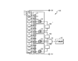
図1は、一実施形態によるバッテリ・システム101を示す図面である。図1を参照すれば、バッテリ・システム101は、バッテリ10、複数の測定部20、第1絶縁回路(isolator)30及びプロセッサ40を含む。
FIG. 1 is a diagram illustrating a
バッテリ10は、外部電源から伝えられた電力を保存する。充電動作によって電力を保存し、放電動作の間、保存した電力を負荷に伝達する。バッテリ10は、正極が正極端子50と連結され、負極が負極端子51と連結され、正極端子50及び負極端子51を介して、充放電を行う。
The
バッテリ10は、直列、並列、または直列と並列との組み合わせで連結された複数のバッテリ・モジュール11を含むことができる。また、複数のバッテリ・モジュール11それぞれは、少なくとも1つのバッテリセル12を含むことができる。バッテリ・モジュール11に、複数のバッテリセル12が含まれる場合、バッテリ・モジュール11内のバッテリセル12は、直列及び/または並列に連結される。各バッテリセル12は、充電可能な二次電池である。本発明の実施形態では、バッテリ・モジュール11及びバッテリセル12が直列に連結されるが、本発明は、これに限定されるものではない。
The
それぞれの測定部20は、バッテリ・モジュール11に含まれたバッテリセル12に対する一つ以上の特性をモニタリングし、バッテリセル12のデータを獲得する。測定部20は、例えば、バッテリセル12の電圧や充電状態、温度などを測定する。測定部20は、複数の第1アナログ・フロントエンド(AFE:analog front end、以下「AFE」または「制御回路」という)21と、第2 AFE 22と、を含む。測定部20は、複数の第1 AFE 21と第2 AFE 22とを1つの回路基板に含むことができる。
Each
第1 AFE 21は、少なくとも1つのバッテリ・モジュール11と連結され、バッテリ・モジュール11に含まれたバッテリセル12の多様な状態をモニタリングする。第1 AFE 21は、例えば、バッテリセル12をモニタリングするとき、周期的または非周期的に測定した値を獲得することができる。しかし、データを獲得する方法は、これに限定されるものではない。例えば、第1 AFE 21は、第2 AFE 22またはプロセッサ40からの制御信号によって、測定した値を獲得することもできる。
The first AFE 21 is connected to at least one
それぞれの特定第1 AFE 21は、モニタリング結果、すなわち、獲得したデータを直列に連結した後、第1 AFE 21に伝送する。その後、第1 AFE 21は、前記特定第1 AFE 21からデータを受信すれば、受信したデータを、自体が直接抽出したデータと共に、その次の第1 AFE 21に伝送する。直列に連結された複数の第1 AFE 21のうち、最後に位置した第1 AFE 21、すなわち、メイン第1 AFE 23は、測定部20に含まれたあらゆる第1 AFE 21が獲得したあらゆるデータを受信する。
Each specific first AFE 21 transmits the monitoring result, that is, the acquired data, to the
図1の実施形態で、バッテリセル12は、直列に連結されており、従って、基準またはグラウンドになる基準バッテリセル12から遠ざかるほど電位差が発生する。バッテリ・モジュール11で、下に位置したバッテリセル12が、基準バッテリセルになってもよい。本実施形態で、第1 AFE 21は、高電位から低電位に抽出したデータを伝送し、低い電位のバッテリセル12と連結される第1 AFE 21がメイン第1 AFE 23として動作し、獲得したあらゆるデータを収集する。そして、メイン第1 AFE 23は、受信したあらゆるデータと、直接獲得したデータとを第2 AFE 22に伝送する。すなわち、1つの測定部20で獲得されたあらゆるデータが、メイン第1 AFE 23で集められ、第2 AFE 22に伝送される。
In the embodiment of FIG. 1, the
それぞれの第2 AFE 22は、複数の第1 AFE 21が獲得したデータを、メイン第1 AFE 23のうち一つから受信する。また、第2 AFE 22は、他の第2 AFE 22で集めたデータを受信し、ならびに、他の第2 AFE 22で受信したデータ、および、第1 AFE 21のうち一つから集めたデータをさらにその他の第2 AFE 22に伝送する。
Each second AFE 22 receives data acquired by the plurality of
他の実施形態として、複数の測定部20は、バッテリセル12の状態を測定するために、直列に連結されてもよい。最も低い電位に位置した測定部20、すなわち、最も下に位置した測定部20に含まれた第2 AFE 22は、次の測定部20に含まれた第2 AFE 22に、集めたデータを伝送する。ここで、次の測定部20とは、以前の測定部20より高い電位に位置した測定部20を意味する。メイン第2 AFE 25、すなわち、最も上に位置した第2 AFE 22は、バッテリ10に含まれたあらゆるバッテリセル12のデータを集める。メイン第2 AFE 25は、集めたデータを第1絶縁回路30に伝送する。
As another embodiment, the plurality of
他の実施形態として、最初の測定部20に含まれた最後の第1 AFE 21に連結されたバッテリセル12のうち、最も下のバッテリセル12の負の電極側電位が、基準(グラウンド)になってもよい。前記基準になるバッテリセル12と連結された第1 AFE 21より上にあるAFE 21は、正の電圧についてのデータを測定し、前記基準になるバッテリセル12と連結された第1 AFE 21より下にあるAFE 21は、負の電圧についてのデータを測定する。
As another embodiment, among the
第1絶縁回路30は、メイン第2 AFE 25とプロセッサ40との間のデータ伝送経路を含む。第1絶縁回路30は、複数の測定部20とプロセッサ40とのグラウンドを互いに分離して絶縁する。第1絶縁回路30としては、例えば、レベルシフト(level shift)回路、光アイソレータ(optical isolator)など多様な回路が使われてもよい。
The
プロセッサ40は、第1絶縁回路30を介して受信したバッテリセル12についてのデータを使用し、バッテリ10の充放電を制御する。
The
第1絶縁回路30の最大耐圧(tolerance voltage)は、バッテリ・システム101の構成によって決定される。本実施形態では、前述のように、第2 AFE 22は、低電位から高電位に、集めたデータを順次に伝送する。基準になるバッテリセル12と電気的に連結されたメイン第2 AFE 25は、第1絶縁回路30と連結されてデータを送受信する。本実施形態で、第1絶縁回路30には、3個の測定部20に対応するバッテリ・モジュール11の電位差に該当する電圧がかかり、従って第1絶縁回路30は、バッテリ・システム101の総電圧の電圧レベルに耐える。例えば、1つのバッテリセル12が約4Vであり、1つのバッテリ・モジュール11に、10個のバッテリセル12が直列に連結される場合、それぞれのバッテリ・モジュール11は、40Vを有する。3個のバッテリ・モジュール11が存在し、各バッテリ・モジュール11は、第1測定部20の下に位置するので、本実施形態による第1絶縁回路30は、約360Vレベルの耐圧を有すればよい。
The maximum tolerance voltage of the
前述のように、メイン第2 AFE 25、または第1絶縁回路30のグラウンド電位は、最初の測定部20のメイン第1 AFE 23と連結されたバッテリ・モジュール11に含まれた複数のバッテリセル12のうち、最も下に位置したバッテリセル12の負極の電位となる。メイン第2 AFE 25および第1絶縁回路30にかかる電圧は、最初の測定部20が担当するバッテリ・モジュール11の総電圧である120V(40Vx3)と、最初の測定部20の下に位置した残りの測定部20が担当するバッテリ・モジュール11の総電圧である−360V(−120Vx3)とである。従って、メイン第2 AFE 25や第1絶縁回路30は、約360Vの電圧に耐える。
As described above, the ground potential of the main
以下、あらゆる例示では、各バッテリセル12の出力電圧を約4Vとし、各バッテリ・モジュール11の出力電圧を約40Vとする。しかし、本発明は、これに限定されるものではなく、バッテリセル12及びバッテリ・モジュール11の出力電圧は、変更されてもよい。
Hereinafter, in all examples, the output voltage of each
他の実施形態として、最も低い電位に位置した測定部20、すなわち、メイン第2 AFE 25を含む最も下に位置した測定部20に含まれる第2 AFE 22へ、獲得したデータが伝送される。第1絶縁回路30のグラウンド電位は、最も下に位置したバッテリセル12の負極の電位である。従って、もし第1絶縁回路30が最も低い電位の第2 AFE 22からデータを受信すれば、第1絶縁回路30は、4個の測定部20が担当するバッテリ・モジュール11の電位差に該当する電圧に耐えらねばならない。すなわち、第1絶縁回路30は、約480V以上の耐圧を有せねばならない。しかし、ある素子または回路で要求される耐圧が高いほど、その素子または回路を製造し難く、かつコストが上昇する。また、素子や回路の製造コストの上昇量は、素子や回路で要求される耐圧の増加量に比例するものではなく、要求される耐圧が上昇することによって、製造コストが幾何級数的に増える。
In another embodiment, the acquired data is transmitted to the
前記のように、本実施形態によるバッテリ・システム101によれば、バッテリセル12から獲得したデータを、プロセッサ40に伝送するにあたり、絶縁回路と連結されるメイン第2 AFE 25を、最上端の第1 AFE 21や最下端の第1 AFE 21に電気的に連結させないので、絶縁回路などの最大素子耐圧を低減する。
As described above, according to the
図2は、他の実施形態によるバッテリ・システム102を示す図面である。図2を参照すれば、バッテリ・システム102は、バッテリ10、複数の測定部20、第1絶縁回路30及びプロセッサ40を含む。本実施形態によるバッテリ・システム102は、図1のバッテリ・システム101と各構成の機能が類似している。
FIG. 2 is a diagram illustrating a
それぞれの第2 AFE 22は、複数の第1 AFE 21が獲得したデータを、メイン第1 AFE 23から受信する。また、それぞれの第2 AFE 22は、他の第2 AFE 22で集めたデータを受信し、他の第2 AFE 22で受信したデータを、さらにその他の第2 AFE 22に伝送することができる。
Each
複数の測定部20が直列に連結されている本実施形態によるバッテリ・システム102で、メイン第2 AFE 25は、複数の直列に連結された測定部20のうち、高電位側から二番目に位置した測定部20に含まれた第2 AFE 22である。従って、二番目の測定部に含まれた最後の第1 AFE 21と電気的に連結されたバッテリセル12の負極が、基準(グラウンド)レベルになる。従って、最も高い電位の測定部20に含まれた第2 AFE 22は、メイン第2 AFE 25に、集めたデータを伝送する。また、メイン第2 AFE 25より低い電位の測定部20に含まれた第2 AFE 22は、低電位から高電位に、集めたデータを伝送する。
In the
前述のように、第1絶縁回路30は、バッテリ・システム102の構成によって、要求される最大耐圧が決定される。本実施形態では、高電位側から二番目に位置した測定部20の第2 AFE 22であるメイン第2 AFE 25が、第1絶縁回路30と連結されてデータを送受信する。データを伝送するメイン第2 AFE 25の位置上、第1絶縁回路30には、2個の測定部20が担当するバッテリ・モジュール11の電位差に該当する電圧がかかり、従って、第1絶縁回路30は、前記2個の測定部20の電圧と同じレベルの最大要求耐圧を有する。例えば、本実施形態による第1絶縁回路30は、約240Vレベルの最大要求耐圧を有すればよい。
As described above, the required maximum withstand voltage of the
前記の通りに、本実施形態によるバッテリ・システム102によれば、バッテリセル12から獲得したデータを、プロセッサ40に伝送するにあたり、第1絶縁回路30にデータを伝送するメイン第2 AFE 25として、中間電位に位置した第2 AFE 22を使用することにより、第1絶縁回路30の最大要求耐圧を下げるのである。
As described above, according to the
図3は、他の実施形態によるバッテリ・システム103を示す図面である。図3を参照すれば、バッテリ・システム103は、バッテリ10、複数の測定部20、第1絶縁回路30及びプロセッサ40を含む。本実施形態によるバッテリ・システム103は、図1のバッテリ・システム101と各構成の機能が類似している。
FIG. 3 is a diagram illustrating a
それぞれの第2 AFE 22は、複数の第1 AFE 21が獲得したデータをメイン第1 AFE 23から受信する。また、それぞれの第2 AFE 22は、他の第2 AFE 22で集めたデータを受信し、他の第2 AFE 22で受信したデータを、さらにその他の第2 AFE 22に伝送することができる。
Each
このとき、複数の測定部20が直列に連結されている本実施形態によるバッテリ・システム103で、メイン第2 AFE 25は、低電位側から二番目に位置した測定部20に含まれた第2 AFE 22である。従って、最も低い電位の第2 AFE 22は、集めたデータをメイン第2 AFE 25に伝送する。また、メイン第2 AFE 25より高い電位の第2 AFE 22は、高電位から低電位に集めたデータを順次に伝送する。メイン第2 AFE 25が、基準レベル(グラウンド)になる。
At this time, in the
前述のように、第1絶縁回路30は、バッテリ・システム103の構成によって、要求される最大耐圧が決定される。本実施形態では、低電位側から二番目に位置した測定部20に含まれたメイン第2 AFE 25が、第1絶縁回路30と連結されてデータを送受信する。データを伝送するメイン第2 AFE 25の位置上、第1絶縁回路30には、最大3個の測定部20が担当するバッテリ・モジュール11の電位差に該当する電圧がかかり、従って、第1絶縁回路30は、前記3個の測定部20の電圧と同じレベルの最大要求耐圧を有する。例えば、本実施形態による第1絶縁回路30は、約360Vレベルの最大要求耐圧を有すればよい。
As described above, the required maximum withstand voltage of the
前記の通りに、本実施形態によるバッテリ・システム103によれば、バッテリセル12から獲得したデータを、プロセッサ40に伝送するにあたり、第1絶縁回路30にデータを伝送するメイン第2 AFE 25として、中間電位に位置した第2 AFE 22を使用することにより、第1絶縁回路30の最大要求耐圧を下げるのである。
As described above, according to the
図4は、一実施形態によるバッテリ・システム101ないし103の制御方法を示すフローチャートである。図4を参照すれば、複数の第1 AFE 21ごとに連結されたバッテリ・モジュール11に含まれたバッテリセル12のデータを獲得する(S10)。複数の第1 AFE 21のそれぞれは、同じ測定部20に含まれたメイン第1 AFE 23に、獲得したデータを伝送する(S11)。
FIG. 4 is a flowchart illustrating a method for controlling the
データを受信し、データを獲得したメイン第1 AFE 23は、集めたデータを対応する第2 AFE 22に伝送する(S12)。そして、データを受信した第2 AFE 22のそれぞれは、受信したデータを、メイン第2 AFE 25に伝送する(S13)。メイン第2 AFE 25は、最も低い電位の測定部20に含まれた第2 AFE 22以外の第2 AFE 22でありうる。メイン第2 AFE 25は、受信した情報を第1絶縁回路30に伝送し(S14)、第1絶縁回路30は、受信した情報をプロセッサ40に伝送する(S15)。他の実施形態として、前記段階は、既設定の周波数、またはプロセッサ40によって決定された時間で反復されてもよい。
The main
前記の通りに、バッテリ・システム101ないし103によれば、バッテリセル12から獲得したデータを、プロセッサ40に伝送するにあたり、第1絶縁回路30にデータを伝送するメイン第2 AFE 25の位置を適切に選択することにより、第1絶縁回路30の最大要求耐圧を下げるのである。
As described above, according to the
図1ないし図4では、各測定部20に含まれた第2 AFE 22が、複数の第1 AFE 21のうち、最も低い電位のメイン第1 AFE 23からデータを受信すると説明したが、これに限定されるものではない。すなわち、それぞれの測定部20に含まれた第2 AFE 22は、例えば、最も高い電位あるいは他の電位の第1 AFE 21からデータを受信することも可能である。
1 to 4, it has been described that the
また、第2 AFE 22が連結される第1 AFE 21の位置が、測定部20ごとに異なって設定されもする。例えば、最も上に位置した測定部20は、最も下に位置した第1 AFE 21をメイン第1 AFE 23とし、残りの測定部20は、最も上に位置した第1 AFE 21を、メイン第1 AFE 23とすることもできるのである。
Further, the position of the
図1の実施形態の場合、最も上に位置した測定部20が、最も上に位置した第1 AFE 21を、メイン第1 AFE 23とした場合、第1絶縁回路30の最大要求耐圧を下げることができなくなる。従って、図1の実施形態の場合、最も上に位置した第1 AFE 21を除外した第1 AFE 21をメイン第1 AFE 23として使用せねばならない。
In the case of the embodiment of FIG. 1, when the
また、図示されてはいないが、最も下に位置した測定部20で、最も下に位置した第1 AFE 21以外の第1 AFE 21が、メイン第1 AFE 23として設定された場合であるならば、第1絶縁回路30が最も下に位置した測定部20に含まれた第2 AFE 22からデータを受信することもできるのである。
Although not shown, if the
図5は、他の実施形態によるバッテリ・システム104を示す図面である。図5を参照すれば、バッテリ・システム104は、バッテリ10、複数の測定部20、第1絶縁回路30、プロセッサ40及び複数の第2絶縁回路60を含む。本実施形態によるバッテリ・システム104は、図1のバッテリ・システム101と各構成の機能が実質的に同一である。
FIG. 5 is a diagram illustrating a
第2 AFE 22は、複数の第1 AFE 21が獲得したデータを、メイン第1 AFE 23から受信する。また、第2 AFE 22は、他の第2 AFE 22で集めたデータを受信し、および、他の第2 AFE 22で受信したデータ、および自分自身が含まれた測定部20の第1 AFE 21から集めたデータを、さらにその他の第2 AFE 22に伝送する。
The
さらに、本実施形態によるバッテリ・システム104で、複数の第2 AFE 22間でのデータの送信及び受信は、第2絶縁回路60を介してなされる。すなわち、第2絶縁回路60は、第2 AFE 22間のデータ伝送経路を提供する。第2絶縁回路60は、測定部20間のグラウンドを分離して絶縁する。第2絶縁回路60としては、例えば、レベルシフト回路、光アイソレータなど多様な回路が使われてもよい。
Further, in the
第1絶縁回路30及び第2絶縁回路60は、バッテリ・システム104の構成によって、要求される最大耐圧が決定される。本実施形態では、第2 AFE 22間では、第2絶縁回路60を介してデータを伝送するので、それぞれの第2絶縁回路60が、約120Vの最大要求耐圧を有することができる。また、メイン第2 AFE 25が、第2絶縁回路60を介して、他の複数の第2 AFE 22からデータを受信するので、第1絶縁回路30もまた、約120Vの最大要求耐圧を有することができる。
The required maximum withstand voltage of the
本実施形態によるバッテリ・システム104によれば、バッテリセル12から獲得したデータを、プロセッサ40に伝送するにあたり、第2 AFE 22間で、第2絶縁回路60を介して獲得したデータを伝送するように構成し、第1絶縁回路30及び第2絶縁回路60の最大要求耐圧を下げるのである。また前述のように、素子や回路の製造コストは、素子や回路で要求される最大耐圧の増加量に比例するものではなく、要求される最大耐圧が上昇することによって、製造コストが幾何級数的に増える。従って、本実施形態によるバッテリ・システム104によれば、絶縁回路の個数が増加するにもかかわらず、製造コストを低減させる。
According to the
図6及び図7は、他の実施形態によるバッテリ・システム105,106を示す図面である。図6及び図7を参照すれば、バッテリ・システム105,106は、図5のバッテリ・システム104と比較し、第1絶縁回路30が連結されるメイン第2 AFE 25を変更した点で違いがある。それ以外には、バッテリ・システム105,106は、図5のバッテリ・システム104と各構成の機能が類似している。
6 and 7 are diagrams illustrating
図8は、他の実施形態によるバッテリ・システム104ないし106の制御方法を示すフローチャートである。図8を参照すれば、複数の第1 AFE 21ごとに連結されたバッテリ・モジュール11に含まれたバッテリセル12のデータを獲得する(S20)。複数の第1 AFE 21は、それぞれ測定部20に含まれたメイン第1 AFE 23に、獲得したデータを伝送する(S21)。
FIG. 8 is a flowchart illustrating a method for controlling the
データを受信し、データを集めたメイン第1 AFE 23は、受信して集めたデータを、対応する第2 AFE 22に伝送する(S22)。そして、データを受信した第2 AFE 22は、受信したデータを、第2絶縁回路60を介して、メイン第2 AFE 25に伝送する(S23)。メイン第2 AFE 25は、最も低い電位の測定部20以外の測定部20に含まれた第2 AFE 22でありうる。
The main
メイン第2 AFE 25は、受信した情報を、第1絶縁回路30を介して、プロセッサ40に伝送する(S24)。前記のように、本実施形態によるバッテリ・システム104ないし106によれば、バッテリセル12から獲得したデータを、プロセッサ40に伝送するにあたり、第2 AFE 22間で、第2絶縁回路60を介してデータを伝送するように構成することによって、第1絶縁回路30及び第2絶縁回路60の最大要求耐圧を下げるのである。また、前述のように、素子や回路の製造コストの上昇量は、素子や回路の最大要求耐圧の増加量に比例するものではなく、要求される最大耐圧が上昇することによって、製造コストが幾何級数的に増える。従って、本実施形態によるバッテリ・システム104ないし106によれば、絶縁回路の個数が増加するにもかかわらず、製造コストを下げるのである。
The main
一方、図5ないし図8では、各測定部20に含まれた第2 AFE 22が、複数の第1 AFE 21のうち、最も低い電位のメイン第1 AFE 23からデータを受信すると説明しているが、それに限定されるものではない。すなわち、それぞれの測定部20に含まれた第2 AFE 22は、例えば、最も高い電位あるいは他の電位に位置した第1 AFE 21からデータを受信することもできるのである。
On the other hand, in FIG. 5 to FIG. 8, it is described that the
また、第2 AFE 22が連結される第1 AFE 21の位置が、測定部20ごとに異なって設定されもする。すなわち、例えば、最も上に位置した測定部20は、最も下に位置した第1 AFE 21を、メイン第1 AFE 23として使用し、残りの測定部20は、最も上に位置した第1 AFE 21を、メイン第1 AFE 23として使用することもできるのである。
Further, the position of the
また、図示されてはいないが、図5ないし図8の実施形態の場合、それぞれの測定部20間に、第2絶縁回路60が備わるので、最も下に位置した測定部20に含まれた第2 AFE 22からデータを受信することもできるのである。
Although not shown, in the case of the embodiment of FIGS. 5 to 8, since the
図9は、一実施形態による電力保存システム1を示す図面である。図9を参照すれば、本実施形態による電力保存システム1は、発電システム2及び系統3からの電力を負荷4に供給する。
FIG. 9 is a diagram illustrating a
発電システム2は、エネルギー源を利用し、電力を生産するシステムである。発電システム2は、生産した電力を電力保存システム1に供給する。発電システム2は、例えば、太陽光発電システム、風力発電システム、潮力発電システムなどであってもよい。しかし、それらは例示的なものであり、発電システム2は、前述の種類に限定されるものではない。発電システム2は、太陽熱や地熱など新再生エネルギーを利用して電力を生産するいずれの発電システムも含むことができる。
The
系統3は、発電所、変電所、送電線などを具備する。系統3は、正常状態である場合、電力保存システム1に電力を供給し、負荷4及び/またはバッテリ10に電力を供給する。系統3が非正常状態である場合、系統3から電力保存システム1への電力供給は中断され、電力保存システム1から系統3への電力供給もまた中断される。
The system 3 includes a power plant, a substation, a transmission line, and the like. When the grid 3 is in a normal state, the grid 3 supplies power to the
負荷4は、発電システム2で生産された電力、バッテリ10に保存された電力、または系統3から供給された電力を消費する。家庭や工場などが負荷4の一例である。
The load 4 consumes electric power produced by the
電力保存システム1は、発電システム2で生産した電力をバッテリ10に保存し、生産した電力を系統3に供給することができる。また、電力保存システム1は、バッテリ10に保存された電力を系統3に供給したり、系統3から供給された電力を、バッテリ10に保存することができる。また、電力保存システム1は、系統3が非正常状態である場合、例えば、停電が発生した場合には、UPS(uninterruptible power supply)動作を遂行し、負荷4に電力を供給することができる。また、電力保存システム1は、系統3が正常である状態でも、発電システム2が生産した電力や、バッテリ10に保存されている電力を負荷4に供給することができる。
The
電力保存システム1は、電力変換を制御する電力制御部(PCS:power control system)200、バッテリ管理部(BMS:battery management system)70及びバッテリ10を含む。
The
PCS 200は、発電システム2、系統3、バッテリ10の電力を適切な電力に変換し、変換された電力を必要なところに供給する。本実施形態で、PCS 200は、電力変換部210、DC(direct current)リンク部220、インバータ230、コンバータ240、第1スイッチ250、第2スイッチ260及び統合制御器270を含む。しかし、他の形態のPCSが使われもするのである。
The
電力変換部210は、発電システム2と、DCリンク部220との間に連結される。電力変換部210は、発電システム2で生産した電力をDCリンク部220に伝達し、出力電圧を、DCリンク電圧に変換する。特に、発電システム2が、太陽光で電力を生産する場合、電力変換部210は、日射量、温度などの変化によって、発電システム2で生産する電力を最大に得ることができるように、最大電力ポイント追跡(MPPT:maximum power point tracking)制御を行うMPPTコンバータを含んでもよい。
The
DCリンク電圧は、発電システム2または系統3での瞬時電圧降下、負荷4でのピーク負荷発生などにより、不安定になる場合がある。しかし、DCリンク電圧は、コンバータ240及びインバータ230の正常動作のために、安定化される必要がある。DCリンク部220は、DCリンク電圧の安定化のために、例えば、大容量キャパシタなどを具備することができ、DCリンク部220は、電力変換部210とインバータ230との間に連結され、DCリンク電圧を維持させる。
The DC link voltage may become unstable due to an instantaneous voltage drop in the
インバータ230は、DCリンク部220と第1スイッチ250との間に連結される電力変換器である。インバータ230は、放電モードで、発電システム2及び/またはバッテリ10から出力されたDCリンク電圧を、系統3の交流(AC)電圧に変換して出力するインバータを含んでもよい。また、インバータ230は、充電モードで、系統3の電力をバッテリ10に保存するために、系統3の交流電圧を整流し、DCリンク電圧に変換して出力する整流回路を含んでもよい。インバータ230は、双方向インバータであり、または複数のインバータ回路を含んでもよい。
インバータ230は、系統3に出力される交流電圧から高調波を除去するためのフィルタを含んでもよい。また、インバータ230は、無効電力の発生を抑制するために、インバータ230から出力される交流電圧の位相と、系統3の交流電圧の位相とを同期化させるための位相同期ループ(PLL)回路を含んでもよい。それ以外に、インバータ230は、電圧変動範囲制限、力率改善、直流成分除去、過度現象(transient phenomena)保護のような機能を行うことができる。
コンバータ240は、DCリンク部220とバッテリ10との間に連結される電力変換器である。コンバータ240は、放電モードで、バッテリ10に保存された電力を、インバータ230で要求する電圧レベル、すなわち、DCリンク電圧に、DC−DC変換して出力するコンバータを含む。また、コンバータ240は、充電モードで、電力変換部210から出力される電力や、インバータ230から出力される電力の電圧を、バッテリ10で要求する電圧レベル、すなわち、充電電圧にDC−DC変換するコンバータを含む。コンバータ240は、双方向コンバータであり、または複数のコンバータ回路を含んでもよい。
第1スイッチ250及び第2スイッチ260は、インバータ230と系統3との間に直列に連結され、統合制御器270の制御によって、オン/オフ動作を遂行し、発電システム2と系統3との間の電流フローを制御する。第1スイッチ250と第2スイッチ260は、発電システム2、系統3及びバッテリ10の状態によって、オン/オフが決定される。例えば、負荷4で要求される電力量が大きい場合、第1スイッチ250及び第2スイッチ260をいずれもオン状態にし、発電システム2、系統3、バッテリ10の電力を、負荷4に供給する。一方、系統3で停電が発生した場合、第2スイッチ260をオフ状態にし、第1スイッチ250をオン状態とする。これにより、発電システム2またはバッテリ10からの電力を負荷4に供給でき、負荷4に供給される電力が系統3に流れる、いわば単独運転を防止し、系統3の電力線などで作業する作業者が感電する事故を防止することができる。
The
統合制御器270は、発電システム2、系統3、バッテリ10及び負荷4の状態をモニタリングし、モニタリング結果によって、電力変換部210、インバータ230、コンバータ240、第1スイッチ250、第2スイッチ260及びBMS 70を制御する。統合制御器270がモニタリングする事項は、系統3に停電が発生しているか否か、発電システム2で電力が生産されているか否かということを含むことができる。また、統合制御器270は、発電システム2の電力生産量、バッテリ10の充電状態、負荷4の電力消費量、時間などをモニタリングすることができる。
The
BMS 70は、バッテリ10に連結され、統合制御器270の制御により、バッテリ10の充放電動作を制御する。BMS 70は、バッテリ10を保護するために、過充電保護機能、過放電保護機能、過電流保護機能、過電圧保護機能、過熱保護機能、セルバランシング(cell balancing)機能などを行うことができる。このために、BMS 70は、バッテリ10の電圧、電流、温度、残余電力量、寿命、充電状態などをモニタリングし、モニタリング結果を統合制御器270に伝送することができる。
The
バッテリ10は、発電システム2で生産された電力、または系統3の電力を保存し、負荷4または系統3に保存した電力を供給する。バッテリ10は、電力保存システム1で要求される電力容量、設計条件などによって、個数を決定することができる。例えば、負荷4の消費電力が大きい場合には、複数のバッテリ10を具備することができ、負荷4の消費電力が小さい場合には、1つのバッテリ10だけを具備することもできるのである。
The
一方、バッテリ10及びBMS 70を含むバッテリ・システム100には、図1ないし図3、及び図5ないし図7で説明したバッテリ・システム101ないし106が使われてもよい。BMS 70は、複数の測定部20、第1絶縁回路30、第2絶縁回路60、プロセッサ40などを含むことができる。
On the other hand, the
前記のように、本実施形態による電力保存システム1では、バッテリ・システム100に含まれる第1絶縁回路30及び/または第2絶縁回路60の最大要求耐圧を下げることができ、これにより、電力保存システム1の設置コストを低減できる。
As described above, in the
本発明は、図面に図示された実施形態を参考にして説明したが、それらは例示的なものに過ぎず、当技術分野の当業者であるならば、それらから多様な変形形態及び均等形態が可能であるという点を理解することができるであろう。従って、本発明の真の技術的保護範囲は、特許請求の範囲の技術的思想によって決まるものである。 Although the present invention has been described with reference to the embodiments illustrated in the drawings, they are illustrative only and various modifications and equivalents will occur to those skilled in the art. You will understand that it is possible. Therefore, the true technical protection scope of the present invention is determined by the technical idea of the claims.
本発明のバッテリ・システム及びこれを含むエネルギー保存システムは、例えば、電力保存関連の技術分野に効果的に適用可能である。 The battery system and the energy storage system including the battery system of the present invention can be effectively applied to, for example, a technical field related to power storage.
1 電力保存システム
2 発電システム
3 系統
4 負荷
10 バッテリ
11 バッテリ・モジュール
12 バッテリセル
20 測定部
21 第1 AFE
22 第2 AFE
23 メイン第1 AFE
25 メイン第2 AFE
30 第1絶縁回路
40 プロセッサ
50 正極端子
51 負極端子
60 第2絶縁回路
70 BMS
100〜106 バッテリ・システム
200 電力制御部
210 電力変換部
220 DCリンク部
230 インバータ
240 コンバータ
250 第1スイッチ
260 第2スイッチ
270 統合制御器
DESCRIPTION OF
22 Second AFE
23 Main 1st AFE
25 Main 2nd AFE
30
100 to 106
Claims (19)
前記バッテリ・モジュールのうち、少なくとも2つのバッテリ・モジュールと連結され、前記少なくとも2つのバッテリ・モジュールの少なくとも1つの特性をモニタリングする少なくとも2つの第1制御回路をそれぞれ含む複数の測定部と、を含み、
それぞれの前記第1制御回路は、絶縁回路を介して伝送された情報に基づいて、前記バッテリ・パックを制御するプロセッサに、モニタリングされた特性と関連した前記情報を伝送し、
前記絶縁回路は、前記伝送された情報を制御回路から受信するが、前記制御回路は、最も低い電位を有するバッテリ・モジュールまたは最も高い電位を有するバッテリ・モジュールに連結されていないことを特徴とするバッテリ・システム。 A battery pack including a plurality of battery modules, each of the battery modules including at least one battery cell;
A plurality of measuring units coupled to at least two of the battery modules and each including at least two first control circuits that monitor at least one characteristic of the at least two battery modules; ,
Each of the first control circuits transmits the information related to the monitored characteristics to a processor that controls the battery pack based on the information transmitted through an isolation circuit;
The isolation circuit receives the transmitted information from the control circuit, but the control circuit is not connected to the battery module having the lowest potential or the battery module having the highest potential. Battery system.
前記プロセッサと通信する絶縁回路と、
複数のバッテリ・モジュールを含むバッテリ・パックであって、前記バッテリ・モジュールのそれぞれが、少なくとも1つのバッテリセルを含む前記バッテリ・パックと、
前記バッテリ・モジュールのうち2つ以上のバッテリ・モジュールと連結される複数の測定部であって、前記連結されたバッテリ・モジュールの少なくとも1つの特性をモニタリングする複数の第1制御回路をそれぞれの前記測定部が含み、それぞれの前記第1制御回路は、前記絶縁回路を介して、前記モニタリングされた特性を示す情報を、前記プロセッサに伝送する前記複数の測定部と、を含み、
前記プロセッサは、前記バッテリ特性情報に基づいて、前記バッテリ・パックを制御し、前記絶縁回路は、前記第1制御回路のうちいずれか一つから、前記バッテリ特性情報を受信するが、前記第1制御回路は、最も低いか、あるいは最も高い電位を有するバッテリ・モジュールのうちいずれか一つと連結されていないことを特徴とするバッテリ・システム。 A processor;
An isolation circuit in communication with the processor;
A battery pack including a plurality of battery modules, each of the battery modules including at least one battery cell;
A plurality of measurement units connected to two or more battery modules among the battery modules, each of which includes a plurality of first control circuits that monitor at least one characteristic of the connected battery modules. Each of the first control circuits includes a plurality of measurement units that transmit information indicating the monitored characteristics to the processor via the isolation circuit;
The processor controls the battery pack based on the battery characteristic information, and the insulation circuit receives the battery characteristic information from any one of the first control circuits. The battery system, wherein the control circuit is not connected to any one of the battery modules having the lowest or highest potential.
前記測定部に連結された前記バッテリ・モジュールのうち最初のバッテリ・モジュールの特性をモニタリングする特定第1制御回路と、
前記測定部に連結された前記バッテリ・モジュールのうち二番目のバッテリ・モジュールの特性をモニタリングする他の特定第1制御回路と、を含み、
前記特定第1制御回路は、前記最初のバッテリ・モジュールのモニタリングされた特性に関連した情報を、前記他の特定第1制御回路に伝送することを特徴とする請求項2に記載のバッテリ・システム。 Each measuring part
A specific first control circuit for monitoring characteristics of the first battery module among the battery modules connected to the measurement unit;
Another specific first control circuit for monitoring characteristics of a second battery module among the battery modules connected to the measurement unit,
3. The battery system according to claim 2, wherein the specific first control circuit transmits information related to a monitored characteristic of the first battery module to the other specific first control circuit. .
前記第2制御回路は、他の測定部の第2制御回路と連結され、
各測定部の前記第2制御回路は、前記最初及び二番目のバッテリ・モジュールの前記モニタリングされた特性を示す情報をプロセッサに伝送することを特徴とする請求項3に記載のバッテリ・システム。 Each measurement unit further includes a second control circuit connected to the other specific first control circuit,
The second control circuit is connected to a second control circuit of another measurement unit,
4. The battery system according to claim 3, wherein the second control circuit of each measuring unit transmits information indicating the monitored characteristics of the first and second battery modules to a processor.
前記電力変換システムに連結されるバッテリ管理部と、
前記バッテリ管理部に連結されるバッテリ・システムと、を含み、
前記バッテリ・システムは、
プロセッサと、
前記プロセッサと通信する絶縁回路と、
複数のバッテリ・モジュールを含むバッテリ・パックであって、前記バッテリ・モジュールのそれぞれが、少なくとも1つのバッテリセルを含む前記バッテリ・パックと、
前記バッテリ・モジュールのうち一つ以上のバッテリ・モジュールと連結される複数の測定部であって、前記連結されたバッテリ・モジュールの少なくとも1つの特性をモニタリングする複数の第1制御回路をそれぞれの前記測定部が含み、それぞれの前記第1制御回路は、前記絶縁回路を介して、前記モニタリングされた特性を示す情報を、前記プロセッサに伝送する前記複数の測定部と、を含み、
前記プロセッサは、前記バッテリ特性情報に基づいて、前記バッテリ・パックを制御し、前記絶縁回路は、前記第1制御回路のうちいずれか一つから、前記バッテリ特性情報を受信するが、前記第1制御回路は、最も低いか、あるいは最も高い電位を有するバッテリ・モジュールのうちいずれか一つと連結されていないことを特徴とするエネルギー保存システム。 A power conversion system coupled to a load and a power source;
A battery management unit coupled to the power conversion system;
A battery system coupled to the battery management unit,
The battery system is
A processor;
An isolation circuit in communication with the processor;
A battery pack including a plurality of battery modules, each of the battery modules including at least one battery cell;
A plurality of measurement units connected to one or more battery modules among the battery modules, each of which includes a plurality of first control circuits that monitor at least one characteristic of the connected battery modules. Each of the first control circuits includes a plurality of measurement units that transmit information indicating the monitored characteristics to the processor via the isolation circuit;
The processor controls the battery pack based on the battery characteristic information, and the insulation circuit receives the battery characteristic information from any one of the first control circuits. The energy storage system, wherein the control circuit is not connected to any one of the battery modules having the lowest or highest potential.
前記測定部に連結された前記バッテリ・モジュールのうち最初のバッテリ・モジュールの特性をモニタリングする特定第1制御回路と、
前記測定部に連結された前記バッテリ・モジュールのうち二番目のバッテリ・モジュールの特性をモニタリングする他の特定第1制御回路と、を含み、
前記特定第1制御回路は、前記最初のバッテリ・モジュールのモニタリングされた特性に関連した情報を、前記他の特定第1制御回路に伝送することを特徴とする請求項15に記載のエネルギー保存システム。 Each measuring part
A specific first control circuit for monitoring characteristics of the first battery module among the battery modules connected to the measurement unit;
Another specific first control circuit for monitoring characteristics of a second battery module among the battery modules connected to the measurement unit,
16. The energy storage system of claim 15, wherein the specific first control circuit transmits information related to the monitored characteristics of the first battery module to the other specific first control circuit. .
前記第2制御回路は、他の測定部の第2制御回路と連結され、
各測定部の前記第2制御回路は、前記最初及び二番目のバッテリ・モジュールの前記モニタリングされた特性を示す情報をプロセッサに伝送することを特徴とする請求項16に記載のエネルギー保存システム。 Each measurement unit further includes a second control circuit connected to the other specific first control circuit,
The second control circuit is connected to a second control circuit of another measurement unit,
The energy storage system according to claim 16, wherein the second control circuit of each measurement unit transmits information indicating the monitored characteristics of the first and second battery modules to a processor.
Applications Claiming Priority (4)
| Application Number | Priority Date | Filing Date | Title |
|---|---|---|---|
| US201161430484P | 2011-01-06 | 2011-01-06 | |
| US61/430,484 | 2011-01-06 | ||
| US13/243,234 US9263776B2 (en) | 2011-01-06 | 2011-09-23 | Battery system and energy storage system including the same |
| US13/243,234 | 2011-09-23 |
Publications (1)
| Publication Number | Publication Date |
|---|---|
| JP2012147660A true JP2012147660A (en) | 2012-08-02 |
Family
ID=45349092
Family Applications (1)
| Application Number | Title | Priority Date | Filing Date |
|---|---|---|---|
| JP2011285988A Pending JP2012147660A (en) | 2011-01-06 | 2011-12-27 | Battery system and energy storage system including the same |
Country Status (5)
| Country | Link |
|---|---|
| US (1) | US9263776B2 (en) |
| EP (1) | EP2475064A3 (en) |
| JP (1) | JP2012147660A (en) |
| KR (1) | KR101234244B1 (en) |
| CN (1) | CN102593884B (en) |
Cited By (1)
| Publication number | Priority date | Publication date | Assignee | Title |
|---|---|---|---|---|
| JP2017503457A (en) * | 2013-10-25 | 2017-01-26 | エルジー・ケム・リミテッド | Battery management system that can transmit secondary protection signals and diagnostic signals using a small number of isolation elements |
Families Citing this family (13)
| Publication number | Priority date | Publication date | Assignee | Title |
|---|---|---|---|---|
| TWI448886B (en) * | 2011-07-28 | 2014-08-11 | Quanta Comp Inc | Rack server system and control method thereof |
| JP5910129B2 (en) | 2012-02-06 | 2016-04-27 | ソニー株式会社 | Power storage device, power system, and electric vehicle |
| DE102014200111A1 (en) * | 2014-01-08 | 2015-07-09 | Robert Bosch Gmbh | A battery management system for monitoring and controlling the operation of a battery and battery system having such a battery management system |
| JP2016135030A (en) * | 2015-01-20 | 2016-07-25 | 株式会社東芝 | Railway storage battery device |
| KR101622511B1 (en) | 2015-02-11 | 2016-05-18 | 엘에스산전 주식회사 | Electricityproviding system including battery energy storage system |
| US10729177B2 (en) * | 2016-07-31 | 2020-08-04 | Altria Client Services Llc | Electronic vaping device, battery section, and charger |
| EP4257995A3 (en) | 2017-06-26 | 2023-11-22 | Siemens Aktiengesellschaft | Method for controlling an uninterruptible power supply system and corresponding power supply system |
| WO2019145997A1 (en) * | 2018-01-23 | 2019-08-01 | Tdk株式会社 | Dc feeding system |
| TWI658676B (en) * | 2018-09-04 | 2019-05-01 | 龍華科技大學 | Novel battery balancer |
| CN109755996A (en) * | 2018-12-14 | 2019-05-14 | 东莞钜威动力技术有限公司 | Mixed equilibrium circuit and daisy chain communicate the battery balanced control device of mixed equilibrium |
| MX2022002516A (en) | 2019-08-28 | 2022-06-24 | Sparkcharge Inc | Battery module with smart electronic isolation systems. |
| CN110635535A (en) * | 2019-10-12 | 2019-12-31 | 常州格力博有限公司 | Voltage equalization system |
| CN110994746B (en) * | 2019-12-31 | 2023-08-22 | 格力博(江苏)股份有限公司 | Voltage equalization system |
Citations (5)
| Publication number | Priority date | Publication date | Assignee | Title |
|---|---|---|---|---|
| JPH0785891A (en) * | 1993-09-10 | 1995-03-31 | Fuji Electric Co Ltd | Method for judging quality of storage battery of uninterrutible power supply unit |
| JPH09139237A (en) * | 1995-11-16 | 1997-05-27 | Matsushita Electric Ind Co Ltd | Monitoring device of battery pack |
| JP2002110259A (en) * | 2000-09-28 | 2002-04-12 | Hitachi Ltd | Storage battery device |
| JP2003009403A (en) * | 2001-06-22 | 2003-01-10 | Osaka Gas Co Ltd | Management system of storage apparatus |
| JP2010203993A (en) * | 2009-03-05 | 2010-09-16 | Denso Corp | Device for monitoring state of assembly battery |
Family Cites Families (15)
| Publication number | Priority date | Publication date | Assignee | Title |
|---|---|---|---|---|
| US5504415A (en) * | 1993-12-03 | 1996-04-02 | Electronic Power Technology, Inc. | Method and apparatus for automatic equalization of series-connected batteries |
| JP2001289886A (en) | 2000-04-03 | 2001-10-19 | Sanyo Electric Co Ltd | Apparatus for measuring battery voltage |
| JP4605952B2 (en) | 2001-08-29 | 2011-01-05 | 株式会社日立製作所 | Power storage device and control method thereof |
| JP4092580B2 (en) | 2004-04-30 | 2008-05-28 | 新神戸電機株式会社 | Multi-series battery control system |
| JP2005318751A (en) | 2004-04-30 | 2005-11-10 | Shin Kobe Electric Mach Co Ltd | Multi-serial battery control system |
| US7317619B2 (en) * | 2004-08-02 | 2008-01-08 | International Business Machines Corporation | Apparatus for inserting and ejecting an electronic enclosure within a cabinet |
| KR101201139B1 (en) | 2006-04-25 | 2012-11-13 | 삼성에스디아이 주식회사 | Protection circuit device of battery pack |
| JP5111275B2 (en) | 2007-09-27 | 2013-01-09 | 株式会社日立製作所 | Monitoring device, power storage device control system using the same, and railway vehicle |
| GB2453207B (en) | 2007-09-27 | 2010-11-10 | Hitachi Ltd | Battery monitoring device, battery control system, and railway vehicle |
| JP2010003536A (en) | 2008-06-20 | 2010-01-07 | Toshiba Corp | Battery pack system |
| JP5351469B2 (en) | 2008-09-03 | 2013-11-27 | 株式会社日立製作所 | Battery control system and battery control method |
| US8227944B2 (en) | 2009-01-06 | 2012-07-24 | O2Micro Inc | Vertical bus circuits |
| US8022669B2 (en) | 2009-01-06 | 2011-09-20 | O2Micro International Limited | Battery management system |
| US20110140662A1 (en) * | 2010-03-31 | 2011-06-16 | Guoxing Li | Balancing system for a battery pack |
| KR101074785B1 (en) * | 2010-05-31 | 2011-10-19 | 삼성에스디아이 주식회사 | A battery management system and control method thereof, and energy storage system including the battery management system |
-
2011
- 2011-09-23 US US13/243,234 patent/US9263776B2/en not_active Expired - Fee Related
- 2011-12-19 KR KR1020110137407A patent/KR101234244B1/en not_active IP Right Cessation
- 2011-12-20 EP EP11194678.6A patent/EP2475064A3/en not_active Withdrawn
- 2011-12-27 JP JP2011285988A patent/JP2012147660A/en active Pending
-
2012
- 2012-01-06 CN CN201210003068.6A patent/CN102593884B/en not_active Expired - Fee Related
Patent Citations (5)
| Publication number | Priority date | Publication date | Assignee | Title |
|---|---|---|---|---|
| JPH0785891A (en) * | 1993-09-10 | 1995-03-31 | Fuji Electric Co Ltd | Method for judging quality of storage battery of uninterrutible power supply unit |
| JPH09139237A (en) * | 1995-11-16 | 1997-05-27 | Matsushita Electric Ind Co Ltd | Monitoring device of battery pack |
| JP2002110259A (en) * | 2000-09-28 | 2002-04-12 | Hitachi Ltd | Storage battery device |
| JP2003009403A (en) * | 2001-06-22 | 2003-01-10 | Osaka Gas Co Ltd | Management system of storage apparatus |
| JP2010203993A (en) * | 2009-03-05 | 2010-09-16 | Denso Corp | Device for monitoring state of assembly battery |
Cited By (2)
| Publication number | Priority date | Publication date | Assignee | Title |
|---|---|---|---|---|
| JP2017503457A (en) * | 2013-10-25 | 2017-01-26 | エルジー・ケム・リミテッド | Battery management system that can transmit secondary protection signals and diagnostic signals using a small number of isolation elements |
| JP2017503458A (en) * | 2013-10-25 | 2017-01-26 | エルジー・ケム・リミテッド | Battery management system that can transmit secondary protection signals and diagnostic signals using a small number of isolation elements |
Also Published As
| Publication number | Publication date |
|---|---|
| EP2475064A3 (en) | 2015-06-10 |
| US20120179399A1 (en) | 2012-07-12 |
| KR20120080125A (en) | 2012-07-16 |
| US9263776B2 (en) | 2016-02-16 |
| EP2475064A2 (en) | 2012-07-11 |
| CN102593884A (en) | 2012-07-18 |
| CN102593884B (en) | 2015-12-09 |
| KR101234244B1 (en) | 2013-02-18 |
Similar Documents
| Publication | Publication Date | Title |
|---|---|---|
| KR101234244B1 (en) | Battery system and power storage system including same | |
| US9865901B2 (en) | Battery system and method for connecting a battery to the battery system | |
| KR101084215B1 (en) | Energy storage system and method for controlling thereof | |
| KR101182431B1 (en) | Battery pack, controlling method of the same, and power storage system including the battery pack | |
| KR101364094B1 (en) | Battery system and energy storage system including the same | |
| KR101146670B1 (en) | Energy management system and method for controlling thereof | |
| KR101074785B1 (en) | A battery management system and control method thereof, and energy storage system including the battery management system | |
| KR101084216B1 (en) | Energy storage system and method for controlling thereof | |
| US10763682B2 (en) | Energy storage system and controlling method thereof | |
| US8482155B2 (en) | Power converting device for renewable energy storage system | |
| US9070908B2 (en) | Battery system, controlling method of the same, and energy storage system including the battery system | |
| JP2011109901A (en) | Power control system and grid-connected energy storage system with the same | |
| JP2011109901A5 (en) | ||
| KR20150081731A (en) | Battery pack, energy storage system including the battery pack, and method of operating the battery pack | |
| KR102234290B1 (en) | Energy storage system and controlling method the same | |
| KR101193174B1 (en) | Battery pack | |
| KR20130138611A (en) | Energy storage system | |
| JP2013085459A (en) | Power storage system and control method therefor | |
| KR20130091951A (en) | Battery pack, controlling method of the same, and power storage system including the battery pack | |
| KR20130054766A (en) | Battery system, method for controlling battery system and energy storage system including the same | |
| KR20130142409A (en) | Battery pack and controlling method of the same | |
| KR20140041156A (en) | Power conversion device |
Legal Events
| Date | Code | Title | Description |
|---|---|---|---|
| A621 | Written request for application examination |
Free format text: JAPANESE INTERMEDIATE CODE: A621 Effective date: 20141201 |
|
| RD03 | Notification of appointment of power of attorney |
Free format text: JAPANESE INTERMEDIATE CODE: A7423 Effective date: 20141201 |
|
| A977 | Report on retrieval |
Free format text: JAPANESE INTERMEDIATE CODE: A971007 Effective date: 20150717 |
|
| A131 | Notification of reasons for refusal |
Free format text: JAPANESE INTERMEDIATE CODE: A131 Effective date: 20150825 |
|
| A521 | Request for written amendment filed |
Free format text: JAPANESE INTERMEDIATE CODE: A523 Effective date: 20151118 |
|
| A131 | Notification of reasons for refusal |
Free format text: JAPANESE INTERMEDIATE CODE: A131 Effective date: 20160412 |
|
| A02 | Decision of refusal |
Free format text: JAPANESE INTERMEDIATE CODE: A02 Effective date: 20161108 |