JP2012147571A - Inverter apparatus and motor drive system - Google Patents
Inverter apparatus and motor drive system Download PDFInfo
- Publication number
- JP2012147571A JP2012147571A JP2011003979A JP2011003979A JP2012147571A JP 2012147571 A JP2012147571 A JP 2012147571A JP 2011003979 A JP2011003979 A JP 2011003979A JP 2011003979 A JP2011003979 A JP 2011003979A JP 2012147571 A JP2012147571 A JP 2012147571A
- Authority
- JP
- Japan
- Prior art keywords
- switching
- smoothing capacitor
- switching element
- switching elements
- inverter device
- Prior art date
- Legal status (The legal status is an assumption and is not a legal conclusion. Google has not performed a legal analysis and makes no representation as to the accuracy of the status listed.)
- Granted
Links
Images


Abstract
Description
本発明は、インバータ装置および電動機ドライブシステムに関する。 The present invention relates to an inverter device and an electric motor drive system.
従来、昇降圧コンバータのスイッチ部を制御し、電圧の昇降圧を行わない状態を維持しつつコンデンサに蓄積されている電荷を放電させる電動機駆動制御装置が知られている(たとえば、特許文献1参照)。 2. Description of the Related Art Conventionally, an electric motor drive control device that controls a switch unit of a buck-boost converter and discharges electric charges accumulated in a capacitor while maintaining a state in which voltage is not boosted or boosted is known (see, for example, Patent Document 1). ).
上記特許文献1では、電動機を用いて放電を行うことができない場合、電動機駆動制御装置が備えた昇降圧コンバータを下アームのスイッチング素子をオン状態とする時間を短く、上アームのスイッチング素子をオン状態とする時間を長くすることにより、放電回路を設けることなくスイッチング損失によってコンデンサに蓄積された電荷を放電させている。 In the above-mentioned Patent Document 1, when discharge cannot be performed using an electric motor, the time required to turn on the lower arm switching element of the buck-boost converter provided in the electric motor drive control device is shortened, and the upper arm switching element is turned on. By extending the time for the state, the charge accumulated in the capacitor is discharged by switching loss without providing a discharge circuit.
しかしながら、上記特許文献1に記載の電動機駆動制御装置では、スイッチング素子を備える昇降圧コンバータを備えていない場合には適用できないという問題点がある。 However, the electric motor drive control device described in Patent Document 1 has a problem that it cannot be applied when a step-up / down converter including a switching element is not provided.
そこで、この発明は、負荷である電動機が接続されていなくても、また、電力変換部を構成する複数のスイッチング素子に故障した素子があっても、特別な放電回路を備えることなく、平滑コンデンサに蓄積された電荷を放電可能なインバータ装置を提供することを目的とする。 Therefore, the present invention provides a smoothing capacitor without a special discharge circuit, even if a motor as a load is not connected, or even if there are failed elements in a plurality of switching elements constituting the power converter. An object of the present invention is to provide an inverter device capable of discharging the electric charge accumulated in the battery.
上記目的を達成するために、この発明の第1の局面によるインバータ装置は、直流電圧源から入力される直流電力を平滑する平滑コンデンサと、平滑コンデンサの出力する直流電力を、複数のスイッチング素子を用いて交流電力に変換する電力変換部と、複数のスイッチング素子の制御を行うスイッチング制御部とを備え、複数のスイッチング素子の故障の有無を検出する機能を有するインバータ装置であって、スイッチング制御部は、直流電圧源を遮断する際に、複数のスイッチング素子に故障のスイッチング素子がある場合は、故障のスイッチング素子および故障のスイッチング素子と逆アームのスイッチング素子を除き、繰り返しスイッチングさせるスイッチングパターンとし、平滑コンデンサに蓄積された電荷を放電するように構成されている。 In order to achieve the above object, an inverter device according to a first aspect of the present invention includes a smoothing capacitor that smoothes DC power input from a DC voltage source, DC power output from the smoothing capacitor, and a plurality of switching elements. An inverter device having a function of detecting the presence / absence of a failure of a plurality of switching elements, comprising: a power conversion unit that converts the AC power into AC power; and a switching control unit that controls a plurality of switching elements. When switching off the DC voltage source, if there are faulty switching elements in the plurality of switching elements, except for the faulty switching element and the switching element of the reverse arm and the reverse arm, a switching pattern that is repeatedly switched, Configured to discharge the charge accumulated in the smoothing capacitor It has been.
この発明の第2の局面による電動機ドライブシステムは、直流電圧源から入力される直流電力を平滑する平滑コンデンサと、平滑コンデンサの出力する直流電力を、複数のスイッチング素子を用いて交流電力に変換する電力変換部と、複数のスイッチング素子の制御を行うスイッチング制御部とを含み、複数のスイッチング素子の故障の有無を検出する機能を有するインバータ装置と、インバータ装置に接続される電動機とを備え、スイッチング制御部は、直流電圧源を遮断する際に、複数のスイッチング素子に故障のスイッチング素子がある場合は、故障のスイッチング素子および故障のスイッチング素子と逆アームのスイッチング素子を除き、繰り返しスイッチングさせるスイッチングパターンとし、平滑コンデンサに蓄積された電荷を放電するように構成されている。 An electric motor drive system according to a second aspect of the present invention is a smoothing capacitor that smoothes DC power input from a DC voltage source, and converts DC power output from the smoothing capacitor into AC power using a plurality of switching elements. An inverter device including a power conversion unit and a switching control unit that controls a plurality of switching elements, and having a function of detecting the presence or absence of a failure of the plurality of switching elements, and an electric motor connected to the inverter device, and switching When the control unit shuts off the DC voltage source and there is a faulty switching element in the plurality of switching elements, the switching unit repeatedly switches except the faulty switching element and the switching element of the faulty switching element and the reverse arm. And the charge accumulated in the smoothing capacitor It is configured to electricity.
本発明によれば、直流電圧源を遮断し、平滑コンデンサに蓄積された電荷を放電する際に、電力変換部を構成する複数のスイッチング素子の故障に応じてスイッチングする素子を選択して放電処理をするので、素子故障時においても電力変換部を2次破壊させることなく平滑コンデンサに蓄積された電荷を放電することができる。また、電力変換部を構成する複数のスイッチング素子を繰り返しスイッチングさせることにより発生するスイッチング損失によって放電処理をするので、負荷である電動機が接続されていなくても、特別な放電回路を備えることなく平滑コンデンサに蓄積された電荷を放電することができる。 According to the present invention, when the DC voltage source is shut off and the electric charge accumulated in the smoothing capacitor is discharged, a discharge process is performed by selecting an element that switches according to a failure of a plurality of switching elements constituting the power conversion unit. Therefore, even when an element fails, the charge accumulated in the smoothing capacitor can be discharged without causing secondary breakdown of the power conversion unit. In addition, since the discharge process is performed by switching loss generated by repeatedly switching a plurality of switching elements constituting the power conversion unit, smoothing can be performed without providing a special discharge circuit even if a motor as a load is not connected. The electric charge stored in the capacitor can be discharged.
以下、本発明の実施形態を図面に基づいて説明する。なお、同一の構成については同一の符号を付することにより、重複説明を適宜省略する。 Hereinafter, embodiments of the present invention will be described with reference to the drawings. In addition, about the same structure, the same code | symbol is attached | subjected and duplication description is abbreviate | omitted suitably.
まず、図1を参照して、本発明の一実施形態による電動機ドライブシステム100のインバータ装置101の構成について説明する。
First, with reference to FIG. 1, the structure of the
図1に示すように、インバータ装置101は、直流電圧源1と、平滑コンデンサ2と、電力変換部3と、スイッチング制御部4と、電流検出器5と、電圧検出器7を備えている。また、インバータ装置101の出力側には、電動機6が接続されている。
As shown in FIG. 1, the
直流電圧源1は、交流電源11と複数のダイオードを含む整流回路12とを備えている。直流電圧源1の正極側には、平滑コンデンサ2の一方電極が接続されている。また、直流電圧源1の負極側には、平滑コンデンサ2の他方電極が接続されている。
The DC voltage source 1 includes an
平滑コンデンサ2は、直流電圧源1からの直流電圧を平滑し、平滑した直流電圧を電力変換部3へ供給する。直流電圧源1の遮断は、図示していないが、直流電圧源1と平滑コンデンサ2の間に装備されるコンタクタをOFFすることにより行われる。
The
電力変換部3は、複数のスイッチング素子31(S1〜S6)を含み、スイッチング制御部4からのゲート信号により駆動される。スイッチング素子S1は、IGBT(絶縁ゲートバイポーラトランジスタ)からなるトランジスタAupと、ダイオードBupとにより構成されている。同様に、スイッチング素子S2(S3、S4、S5、S6)は、トランジスタAun(Avp、Avn、Awp、Awn)と、ダイオードBun(Bvp、Bvn、Bwp、Bwn)とにより構成されている。
The
スイッチング素子S1、S3およびS5は、電力変換部3の上アームを構成し、一方端子は直流電圧源1の正極側に接続されている。また、スイッチング素子S2、S4およびS6は、電力変換部3の下アームを構成し、一方端子は直流電圧源1の負極側に接続されている。また、スイッチング素子S1、S3およびS5の他方端子は、それぞれスイッチング素子S2、S4およびS6の他方端子、および電動機6に接続されている。
Switching elements S 1,
なお、スイッチング素子S1およびS2は電動機6のU相、スイッチング素子S3およびS4は電動機6のV相、スイッチング素子S5およびS6は電動機6のW相のそれぞれの電力変換を行うように構成されている。
The switching elements S1 and S2 are configured to perform power conversion of the U phase of the
スイッチング制御部4は、電力変換部3を構成する6つのスイッチング素子31(S1〜S6)の制御を行うように構成され、スイッチング素子31(S1〜S6)にゲート信号を出力している。このようなスイッチング制御部4は、インバータ装置101に一般的に設けられ、電動機6をドライブする際は、図示していないが、例えば速度制御、電流制御などを実施して生成された電圧指令Vu*、Vv*、Vw*に基づきPWM制御によって、スイッチング素子31(S1〜S6)を駆動するゲート信号を生成する。
The
電流検出器5は、電力変換部3と電動機6との間に接続され、電力変換部3から電動機6に供給されるU相、V相、W相の電流Iu、Iv、Iwを検出して、スイッチング制御部4に出力する。なお、図1には、電流検出器5は相毎に3つ図示しているが、例えばIw=−Iu−Ivの演算で1相分は演算で求めることで省略できる。
The
電圧検出器7は、直流電圧源1が遮断される際、平滑コンデンサ2の電圧を検出し、その電圧検出値をスイッチング制御部4に出力するように構成されている。
The voltage detector 7 is configured to detect the voltage of the
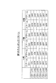
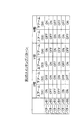
次に、参考までに、図2〜図5を参照して、本発明の一実施形態によるインバータ装置101のスイッチング制御部4によるスイッチング素子31(S1〜S6)の故障(短絡故障および開放故障)の判定動作および故障したスイッチング素子31の特定動作について簡単に説明する。図2は短絡故障のスイッチング素子を特定するために使用する第1のスイッチングパターンを示した図、図3は第1のスイッチングパターンでの切り替え動作を説明するための信号波形図、図4は開放故障のスイッチング素子の特定を行う際に使用する第2のスイッチングパターンを示した図、図5は第2のスイッチングパターンでの切り替え動作を説明するための信号波形図であり、図2、図4に示された各スイッチングパターンは、それぞれスイッチング素子31(S1〜S6)に出力されるゲート信号に対応している。なお、ここでは、スイッチング素子31の故障検出する機能は、スイッチング制御部4が有するとして説明するが、これに限定されるものではない。
Next, for reference, with reference to FIG. 2 to FIG. 5, a failure (short circuit failure and open failure) of the switching element 31 (S1 to S6) by the
(短絡故障のスイッチング素子の特定動作)
まず、スイッチング素子31(S1〜S6)の短絡故障の判定および短絡故障したスイッチング素子の特定が行われる。このとき、スイッチング制御部4は、6つのスイッチング素子31(S1〜S6)のうちの1つのスイッチング素子31をON状態とし、かつ、他のスイッチング素子31をOFF状態とする第1のスイッチングパターン(図2参照)を用いて6つのスイッチング素子31をスイッチングし、ON状態とする1つのスイッチング素子31を順次切り替える(時間t1毎に切り替える(図3参照))。なお、時間t1は、スイッチング素子31に大きい電流(たとえば、上下アームの短絡電流)が流れた場合でもスイッチング素子31が破壊されない長さの時間である。なお、図3には、デッドタイムを考慮していない原理的なスイッチングパターンを示している。
(Specific operation of switching element with short circuit failure)
First, the determination of the short circuit failure of the switching element 31 (S1 to S6) and the identification of the switching element having the short circuit failure are performed. At this time, the
(開放故障のスイッチング素子の特定動作)
次に、スイッチング素子31(S1〜S6)の開放故障の判定および開放故障したスイッチング素子の特定が行われる。このとき、スイッチング制御部4は、3つの相(U相、V相およびW相)のうちの1つの相の上アームまたは下アームの一方のスイッチング素子31をON状態とし、かつ、他方のスイッチング素子31をOFF状態とするとともに、その1つの相以外の2つの相の上アームまたは下アームの一方の2つのスイッチング素子31をOFF状態とし、かつ、他方の2つのスイッチング素子31をON状態とする。すなわち、スイッチング制御部4は、3つの相のうちの1つの相のON状態とする側のアームを他の2つの相と異なるようにした第2のスイッチングパターン(図4参照)で6つのスイッチング素子31をスイッチングする。そして、ON状態とする側のアームを他の2つの相と異なるようにした1つの相と、その1つの相のON状態とする側のアームとを順次切り替える(時間t2毎に切り替える(図5参照))。なお、図5には、デッドタイムを考慮していない原理的なスイッチングパターンを示している。
(Specific operation of switching element with open failure)
Next, the determination of the open failure of the switching element 31 (S1 to S6) and the identification of the switching element having the open failure are performed. At this time, the switching
次に、本発明の一実施形態によるインバータ装置101での直流電圧源1が遮断された時の平滑コンデンサ2に蓄積された電荷の放電動作について説明する。
Next, the discharge operation of the electric charge accumulated in the smoothing
(故障と判定されたスイッチング素子がある場合の放電動作)
スイッチング素子31(S1〜S6)のうち、短絡故障と判定されたスイッチング素子31がある場合には、上述の参考までに説明したスイッチング素子31の判定動作および特定動作で使用したスイッチングパターン(第2のスイッチングパターン(パターンB1〜B6)(図4参照))のうち、短絡故障のスイッチング素子31をON状態とし、短絡故障のスイッチング素子31と逆アームのスイッチング素子31をOFF状態とし、かつ、残り4つのスイッチング素子31の各上下アームを同時にON状態とさせないスイッチングパターン(たとえば、スイッチング素子S1が短絡故障している場合はパターンB1、B5およびB6)で繰り返しスイッチングする動作が行われる。
(Discharge operation when there is a switching element determined to be faulty)
Of the switching elements 31 (S1 to S6), when there is a switching
また、スイッチング素子31(S1〜S6)のうち、開放故障と判定されたスイッチング素子31がある場合には、同じく図4に示している第2のスイッチングパターン(パターンB1〜B6)のうち、開放故障のスイッチング素子31をOFF状態とし、開放故障のスイッチング素子31と逆アームのスイッチング素子31をON状態とし、かつ、残り4つのスイッチング素子31の各上下アームを同時にON状態とさせないスイッチングパターン(たとえば、スイッチング素子S1が開放故障していた場合には、パターンB2、B3およびB4)で繰り返しスイッチングするスイッチング動作が行われる。
Moreover, when there exists the switching
なお、短絡故障しているスイッチング素子31に対してON状態、開放故障しているスイッチング素子31に対してOFF状態にすることは、完全に短絡、あるいは開放していないスイッチング素子31もあることを考慮すると、非常に有効である。
Note that setting the ON state for the switching
これにより、スイッチング制御部4は、故障していないスイッチング素子31のみを用いたスイッチング素子31によるスイッチング損失によって、平滑コンデンサ2に蓄積された電荷を放電する。
Thereby, the switching
(故障と判定されたスイッチング素子がない場合の放電動作)
スイッチング素子31に、短絡故障あるいは開放故障と判定されたスイッチング素子31がない場合(全てのスイッチング素子31が正常な場合)には、上述の参考までに説明したスイッチング素子31のスイッチングパターン(第2のスイッチングパターン(パターンB1〜B6)(図4参照))で6つの全てのスイッチング素子31を繰り返しスイッチングする動作が行われる。
(Discharge operation when there is no switching element determined to be faulty)
When there is no switching
これにより、スイッチング制御部4は、6つのスイッチング素子31により生じるスイッチング損失によって、平滑コンデンサ2に蓄積された電荷を放電する。なお、6つのスイッチング素子31のうち、いくつかのスイッチング素子31の状態を固定して放電処理をしてもよい。
Thereby, the switching
なお、平滑コンデンサ2の蓄積電荷の放電を行う際、上述したように故障したスイッチング素子31を用いないようにすれば、図4に示す第2のスイッチングパターン(B1〜B6)に限らず、図2に示す第1のスイッチングパターン(A1〜A6)や、図6に示す第3のスイッチングパターン(C1、C2)を基本としたパターンを繰り返しスイッチングするようにしてもよい。
In addition, when discharging the accumulated charge of the smoothing
次に、本発明の一実施形態によるインバータ装置101での直流電圧源1が遮断された時の平滑コンデンサ2の異常判定動作について説明する。
Next, the abnormality determination operation of the smoothing
電圧検出器7は、直流電圧源1が遮断される際、平滑コンデンサ2の電圧検出値を所定時間毎にスイッチング制御部4に出力する。スイッチング制御部4は、電圧検出値が所定値1から所定値2になる時間を、平滑コンデンサ2の蓄積電荷の放電時間として測定する。この測定された放電時間が所定値以下である場合に、平滑コンデンサ2に異常(たとえば、コンデンサの容量抜け)があると判定する。
The voltage detector 7 outputs the voltage detection value of the smoothing
なお、放電時間と比較される所定値は、平滑コンデンサ2を正常な平滑コンデンサ2と交換した場合の測定値、あるいは設計値など寿命により劣化する前の状態での放電時間が事前に記憶されるようになっている。さらに、この放電時間と比較される所定値は、スイッチング素子31すべての単位時間あたりのスイッチング回数と、スイッチング周波数の少なくともいずれか一方を考慮して決められる。なお、電圧検出値の電位を決める所定値1、所定値2は、予め決められた値であればよい。
Note that the predetermined value to be compared with the discharge time is stored in advance as a discharge time in a state before deterioration due to life such as a measured value or a design value when the smoothing
また、電圧検出値が所定値1から所定値2になる時間を、平滑コンデンサ2の蓄積電荷の放電時間として、平滑コンデンサ2に異常があるとしたが、上述した放電処理により所定時間内に変化した電圧検出値の変化量を比較するようにしてもよい。
Further, although the time when the voltage detection value becomes the
上記実施形態では、直流電圧源1が、交流電源を整流回路により整流することにより直流を供給する例を示したが、整流回路に代えてPWMコンバータであってもよいし、バッテリーなどの直流電源により直流を供給してもよい。また3相の交流電源を用いて3相の交流を出力する例を示したが、3相以外の相数の交流電源を用いるインバータ装置に適用可能であるとともに、3相以外の相数の交流を出力するインバータ装置にも適用可能である。 In the above embodiment, the DC voltage source 1 supplies the direct current by rectifying the alternating current power supply using the rectifier circuit. However, the DC voltage source 1 may be a PWM converter instead of the rectifier circuit, or a direct current power supply such as a battery. Direct current may be supplied by Moreover, although the example which outputs three-phase alternating current using a three-phase alternating current power supply was shown, it is applicable to the inverter apparatus using alternating current power supplies of the number of phases other than three phases, and alternating current of the number of phases other than three phases It is also applicable to an inverter device that outputs
本発明の実施形態はこのように構成されているので、本実施形態に係るインバータ装置101は、故障していないスイッチング素子31を用い、スイッチング損失だけで平滑コンデンサ2に蓄積された電荷の放電を迅速に行うことができるので、電動機6を負荷として接続しておく必要はないし、故障したスイッチング素子31を無条件にスイッチングすることによる電力変換部の2次的破壊を防止でき、さらに電荷放電のための放電回路を別途設けることを不要とできる。
Since the embodiment of the present invention is configured as described above, the
さらに、平滑コンデンサ2の蓄積電荷の放電時間と、平滑コンデンサ2の電圧を測定するだけで平滑コンデンサ2の異常を容易に判定することができる。これは、平滑コンデンサ2の静電容量を計算し、その計算により取得した静電容量に基づいて平滑コンデンサ2の異常を判定する場合に比べ容易に実施できる。
Furthermore, the abnormality of the smoothing
なお、今回開示された実施形態は、すべての点で例示であって制限的なものではないと考えられるべきである。本発明の範囲は、上記した実施形態の説明ではなく特許請求の範囲によって示され、さらに特許請求の範囲と均等の意味および範囲内でのすべての変更が含まれる。 The embodiment disclosed this time should be considered as illustrative in all points and not restrictive. The scope of the present invention is shown not by the above description of the embodiments but by the scope of claims for patent, and further includes all modifications within the meaning and scope equivalent to the scope of claims for patent.
たとえば、上記実施形態では、スイッチング素子としてIGBTを含むスイッチング素子を用いる例を示したが、たとえば、スイッチング素子としてMOSFET(電界効果トランジスタ)を含むスイッチング素子を用いてもよい。また、電動機を負荷としてインバータ装置に接続する例を示したが、電動機以外の負荷をインバータ装置に接続してもよい。 For example, in the above embodiment, an example in which a switching element including an IGBT is used as the switching element has been described. Moreover, although the example which connects an electric motor as a load to an inverter apparatus was shown, you may connect loads other than an electric motor to an inverter apparatus.
1 直流電圧源
2 平滑コンデンサ
3 電力変換部
4 スイッチング制御部
6 電動機
7 電圧検出器
31、S1、S2、S3、S4、S5、S6 スイッチング素子
DESCRIPTION OF SYMBOLS 1
Claims (8)
前記平滑コンデンサの出力する直流電力を、複数のスイッチング素子を用いて交流電力に変換する電力変換部と、
前記複数のスイッチング素子の制御を行うスイッチング制御部と、を備え、
前記複数のスイッチング素子の故障の有無を検出する機能を有するインバータ装置であって、
前記スイッチング制御部は、前記直流電圧源を遮断する際に、
前記複数のスイッチング素子に故障のスイッチング素子がある場合は、前記故障のスイッチング素子および前記故障のスイッチング素子と逆アームのスイッチング素子を除き、繰り返しスイッチングさせるスイッチングパターンとし、
前記平滑コンデンサに蓄積された電荷を放電するように構成されている、インバータ装置。 A smoothing capacitor for smoothing the DC power input from the DC voltage source;
A power converter that converts the DC power output from the smoothing capacitor into AC power using a plurality of switching elements;
A switching control unit for controlling the plurality of switching elements,
An inverter device having a function of detecting the presence or absence of failure of the plurality of switching elements,
When the switching control unit shuts off the DC voltage source,
When there is a faulty switching element in the plurality of switching elements, except for the faulty switching element and the switching element of the reverse arm and the faulty switching element, a switching pattern for repeated switching,
An inverter device configured to discharge the electric charge accumulated in the smoothing capacitor.
短絡故障のスイッチング素子をON状態、かつ前記短絡故障のスイッチング素子と逆アームのスイッチング素子をOFF状態とし、
開放故障のスイッチング素子をOFF状態、かつ前記開放故障のスイッチング素子と逆アームのスイッチング素子をON状態とし、
他のスイッチング素子は、前記複数のスイッチング素子の各上下アームが同時にはON状態とならないスイッチングパターンである、請求項1に記載のインバータ装置。 The switching pattern is:
The short-circuit fault switching element is turned ON, and the short-circuit fault switching element and the reverse arm switching element are turned OFF,
The switching element of the open failure is turned off, and the switching element of the reverse arm and the switching element of the reverse arm are turned on,
2. The inverter device according to claim 1, wherein the other switching elements are switching patterns in which the upper and lower arms of the plurality of switching elements are not simultaneously turned on.
前記複数のスイッチング素子に故障のスイッチング素子がない場合は、前記複数のスイッチング素子の全てを繰り返しスイッチングさせるスイッチングパターンとし、
前記平滑コンデンサに蓄積された電荷を放電するように構成されている、請求項1または2に記載のインバータ装置。 When the switching control unit shuts off the DC voltage source,
When there is no faulty switching element in the plurality of switching elements, a switching pattern that repeatedly switches all of the plurality of switching elements,
The inverter device according to claim 1, wherein the inverter device is configured to discharge the electric charge accumulated in the smoothing capacitor.
前記スイッチング制御部は、前記平滑コンデンサに蓄積された電荷を放電する際、前記電圧検出値が所定の大きさ変化する時間を放電時間とし、前記放電時間が所定値以下である場合に、前記平滑コンデンサに異常があると判定するように構成されている、請求項1〜3のいずれか1項に記載のインバータ装置。 A voltage detector that detects the voltage of the smoothing capacitor and outputs it as a voltage detection value,
The switching control unit, when discharging the charge accumulated in the smoothing capacitor, sets a time during which the voltage detection value changes to a predetermined magnitude as a discharge time, and when the discharge time is equal to or less than a predetermined value, The inverter device according to claim 1, wherein the inverter device is configured to determine that there is an abnormality in the capacitor.
前記スイッチング制御部は、前記平滑コンデンサに蓄積された電荷を所定時間放電させた際の、前記電圧検出値の変化量が所定値以下である場合に、前記平滑コンデンサに異常があると判定するように構成されている、請求項1〜3のいずれか1項に記載のインバータ装置。 A voltage detector that detects the voltage of the smoothing capacitor and outputs it as a voltage detection value,
The switching control unit determines that the smoothing capacitor is abnormal when the amount of change in the voltage detection value is less than or equal to a predetermined value when the charge accumulated in the smoothing capacitor is discharged for a predetermined time. The inverter device according to claim 1, wherein the inverter device is configured as follows.
前記平滑コンデンサの出力する直流電力を、複数のスイッチング素子を用いて交流電力に変換する電力変換部と、
前記複数のスイッチング素子の制御を行うスイッチング制御部と、を含み、
前記複数のスイッチング素子の故障の有無を検出する機能を有するインバータ装置と、
前記インバータ装置に接続される電動機と、を備え、
前記スイッチング制御部は、前記直流電圧源を遮断する際に、
前記複数のスイッチング素子に故障のスイッチング素子がある場合は、前記故障のスイッチング素子および前記故障のスイッチング素子と逆アームのスイッチング素子を除き、繰り返しスイッチングさせるスイッチングパターンとし、
前記平滑コンデンサに蓄積された電荷を放電するように構成されている、電動機ドライブシステム。 A smoothing capacitor for smoothing the DC power input from the DC voltage source;
A power converter that converts the DC power output from the smoothing capacitor into AC power using a plurality of switching elements;
A switching control unit that controls the plurality of switching elements,
An inverter device having a function of detecting the presence or absence of failure of the plurality of switching elements;
An electric motor connected to the inverter device,
When the switching control unit shuts off the DC voltage source,
When there is a faulty switching element in the plurality of switching elements, except for the faulty switching element and the switching element of the reverse arm and the faulty switching element, a switching pattern for repeated switching,
An electric motor drive system configured to discharge electric charges accumulated in the smoothing capacitor.
Priority Applications (1)
| Application Number | Priority Date | Filing Date | Title |
|---|---|---|---|
| JP2011003979A JP5673114B2 (en) | 2011-01-12 | 2011-01-12 | Inverter device and electric motor drive system |
Applications Claiming Priority (1)
| Application Number | Priority Date | Filing Date | Title |
|---|---|---|---|
| JP2011003979A JP5673114B2 (en) | 2011-01-12 | 2011-01-12 | Inverter device and electric motor drive system |
Publications (2)
| Publication Number | Publication Date |
|---|---|
| JP2012147571A true JP2012147571A (en) | 2012-08-02 |
| JP5673114B2 JP5673114B2 (en) | 2015-02-18 |
Family
ID=46790556
Family Applications (1)
| Application Number | Title | Priority Date | Filing Date |
|---|---|---|---|
| JP2011003979A Active JP5673114B2 (en) | 2011-01-12 | 2011-01-12 | Inverter device and electric motor drive system |
Country Status (1)
| Country | Link |
|---|---|
| JP (1) | JP5673114B2 (en) |
Cited By (4)
| Publication number | Priority date | Publication date | Assignee | Title |
|---|---|---|---|---|
| WO2016072597A1 (en) * | 2014-11-05 | 2016-05-12 | 삼성전자주식회사 | Converter, inverter, device for driving alternating current motor, and air conditioner using same |
| JP2018042412A (en) * | 2016-09-09 | 2018-03-15 | 日産自動車株式会社 | Inverter control apparatus and inverter control method |
| JP2018157650A (en) * | 2017-03-16 | 2018-10-04 | 日産自動車株式会社 | Inverter control apparatus and inverter control method |
| US10541539B1 (en) | 2014-11-05 | 2020-01-21 | Samsung Electronics Co., Ltd. | Converter, inverter, AC motor driving apparatus, and air conditioner using the same |
Citations (4)
| Publication number | Priority date | Publication date | Assignee | Title |
|---|---|---|---|---|
| JPH0880055A (en) * | 1994-08-31 | 1996-03-22 | Toshiba Corp | Inverter device |
| JPH10304673A (en) * | 1997-04-25 | 1998-11-13 | Hitachi Ltd | Discharging circuit of power converter |
| WO2009072460A1 (en) * | 2007-12-03 | 2009-06-11 | Hitachi Medical Corporation | Inverter device and x-ray high-voltage device using the inverter device |
| JP2010130841A (en) * | 2008-11-28 | 2010-06-10 | Nissan Motor Co Ltd | Discharger for inverter |
-
2011
- 2011-01-12 JP JP2011003979A patent/JP5673114B2/en active Active
Patent Citations (4)
| Publication number | Priority date | Publication date | Assignee | Title |
|---|---|---|---|---|
| JPH0880055A (en) * | 1994-08-31 | 1996-03-22 | Toshiba Corp | Inverter device |
| JPH10304673A (en) * | 1997-04-25 | 1998-11-13 | Hitachi Ltd | Discharging circuit of power converter |
| WO2009072460A1 (en) * | 2007-12-03 | 2009-06-11 | Hitachi Medical Corporation | Inverter device and x-ray high-voltage device using the inverter device |
| JP2010130841A (en) * | 2008-11-28 | 2010-06-10 | Nissan Motor Co Ltd | Discharger for inverter |
Cited By (4)
| Publication number | Priority date | Publication date | Assignee | Title |
|---|---|---|---|---|
| WO2016072597A1 (en) * | 2014-11-05 | 2016-05-12 | 삼성전자주식회사 | Converter, inverter, device for driving alternating current motor, and air conditioner using same |
| US10541539B1 (en) | 2014-11-05 | 2020-01-21 | Samsung Electronics Co., Ltd. | Converter, inverter, AC motor driving apparatus, and air conditioner using the same |
| JP2018042412A (en) * | 2016-09-09 | 2018-03-15 | 日産自動車株式会社 | Inverter control apparatus and inverter control method |
| JP2018157650A (en) * | 2017-03-16 | 2018-10-04 | 日産自動車株式会社 | Inverter control apparatus and inverter control method |
Also Published As
| Publication number | Publication date |
|---|---|
| JP5673114B2 (en) | 2015-02-18 |
Similar Documents
| Publication | Publication Date | Title |
|---|---|---|
| US9787084B2 (en) | Motor driving device | |
| JP5849586B2 (en) | 3-level power conversion circuit system | |
| US10128741B2 (en) | Power conversion device | |
| JP5223711B2 (en) | Uninterruptible power system | |
| CN110176898B (en) | Motor drive device including short-circuit determination unit for capacitor of DC link unit | |
| US20200295595A1 (en) | Uninterruptible power supply device | |
| JP2013115994A (en) | Motor drive device having power failure determination part for determining presence or absence of power failure | |
| JP5441481B2 (en) | Inverter device failure diagnosis method | |
| JP5696485B2 (en) | Inverter device and electric motor drive system | |
| US20120275202A1 (en) | Series multiplex power conversion apparatus | |
| KR101356277B1 (en) | Alternating current motor drive device | |
| JP2019213283A (en) | Motor drive device having DC link capacitor short-circuit determination unit | |
| JP5864241B2 (en) | Power converter | |
| JP2008172925A (en) | Backup operation device of matrix converter | |
| JP5673114B2 (en) | Inverter device and electric motor drive system | |
| JP6513249B1 (en) | DC / DC converter | |
| JP2016174444A (en) | Controller, control method and program | |
| JP5302905B2 (en) | Power converter | |
| JP5940840B2 (en) | Power converter | |
| JP5360408B2 (en) | Power converter | |
| JP7149770B2 (en) | Power conversion device and inverter device using the same | |
| JP5445036B2 (en) | Power converter | |
| JP2009219225A (en) | Vehicle driving system | |
| Azer et al. | A new fault-tolerant method for 5-level active neutral point clamped inverter using sinusoidal PWM | |
| JP4780305B2 (en) | Inverter device |
Legal Events
| Date | Code | Title | Description |
|---|---|---|---|
| A621 | Written request for application examination |
Free format text: JAPANESE INTERMEDIATE CODE: A621 Effective date: 20121120 |
|
| A977 | Report on retrieval |
Free format text: JAPANESE INTERMEDIATE CODE: A971007 Effective date: 20130918 |
|
| A131 | Notification of reasons for refusal |
Free format text: JAPANESE INTERMEDIATE CODE: A131 Effective date: 20130924 |
|
| A131 | Notification of reasons for refusal |
Free format text: JAPANESE INTERMEDIATE CODE: A131 Effective date: 20140408 |
|
| A521 | Written amendment |
Free format text: JAPANESE INTERMEDIATE CODE: A523 Effective date: 20140514 |
|
| TRDD | Decision of grant or rejection written | ||
| A01 | Written decision to grant a patent or to grant a registration (utility model) |
Free format text: JAPANESE INTERMEDIATE CODE: A01 Effective date: 20141202 |
|
| A61 | First payment of annual fees (during grant procedure) |
Free format text: JAPANESE INTERMEDIATE CODE: A61 Effective date: 20141215 |
|
| R150 | Certificate of patent or registration of utility model |
Ref document number: 5673114 Country of ref document: JP Free format text: JAPANESE INTERMEDIATE CODE: R150 |