JP2012147162A - Apparatus capable of detecting code, control method of apparatus, and program - Google Patents
Apparatus capable of detecting code, control method of apparatus, and program Download PDFInfo
- Publication number
- JP2012147162A JP2012147162A JP2011002927A JP2011002927A JP2012147162A JP 2012147162 A JP2012147162 A JP 2012147162A JP 2011002927 A JP2011002927 A JP 2011002927A JP 2011002927 A JP2011002927 A JP 2011002927A JP 2012147162 A JP2012147162 A JP 2012147162A
- Authority
- JP
- Japan
- Prior art keywords
- code
- detected
- document
- image data
- output
- Prior art date
- Legal status (The legal status is an assumption and is not a legal conclusion. Google has not performed a legal analysis and makes no representation as to the accuracy of the status listed.)
- Pending
Links
Images


Landscapes
- Control Or Security For Electrophotography (AREA)
- Facsimiles In General (AREA)
Abstract
Description
本発明は、画像データから、コードの検出ができる装置、装置の制御方法、プログラムに関する。 The present invention relates to a device capable of detecting a code from image data, a method for controlling the device, and a program.
特許文献1は、原稿にQRコード等のコードがある場合に、その原稿をスキャンして得られた画像データからそのコードの検出、復号を行っている。
復号の結果、出力許可情報が得られた場合に、その画像データの印刷されたコピー物を排紙し、出力禁止情報が得られた場合には、コピー物の排紙を行っていない。
また、その画像データからコードの検出ができなかった場合にも、排紙を行っていなかった。
In Patent Document 1, when a code such as a QR code is included in a document, the code is detected and decoded from image data obtained by scanning the document.
As a result of decoding, when output permission information is obtained, a copy of the image data printed is discharged, and when output prohibition information is obtained, the copy is not discharged.
Further, even when the code could not be detected from the image data, the paper was not discharged.
つまり、印刷物に出力許可情報を示すコードがあった場合にのみ、その印刷物のコピー物を排紙していたのである。 That is, only when the printed material has a code indicating the output permission information, the printed material is discharged.
ところで、出力許可のコードが付加された原稿でも、原稿の置き方がずれていたり、原稿が折れていてコードが検出されない場合もある。
この場合、コードが検出されないのでコピー物は排紙されないが、ユーザとしては、出力許可のコードが付加されているのに何故排紙されないのか理由が判らず、装置の管理者に頻繁に問い合わせが発生するという問題があった。
By the way, even in a document to which an output permission code is added, there is a case where the method of placing the document is shifted or the document is folded and the code is not detected.
In this case, the copy is not discharged because the code is not detected, but the user does not know why the paper is not discharged even though the output permission code is added, and frequently asks the administrator of the apparatus. There was a problem that occurred.
上記課題を解決するため、本発明の画像処理装置は、画像データからコードを検出できない場合に、その画像データの出力を行わない設定を行うことのできる装置であって、コードを検出できない場合に、コードが検出できなかったが故にその画像データの出力を行わなかった旨を表示画面に表示することを特徴とする。 In order to solve the above-described problems, the image processing apparatus of the present invention is an apparatus that can perform a setting not to output the image data when the code cannot be detected from the image data, and when the code cannot be detected. Further, the fact that the image data was not output because the code could not be detected is displayed on the display screen.
原稿に付加されたコードが検出されずに出力禁止となった場合に、ユーザがその事由を知ることができる。 If the code added to the document is not detected and output is prohibited, the user can know the reason.
以下、本発明を実施するための最良の形態について図面を用いて説明する。 The best mode for carrying out the present invention will be described below with reference to the drawings.
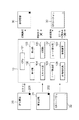
図1は、本発明に適用されるシステムを示すシステム図である。
画像処理装置10は、CPU101、受付部102、表示部103、スキャナ部104、印刷部105、コード検出部106、コード復号部107、画像処理部108、記憶装置109からなる。
CPU101は、記憶装置109内部のプログラムを実行することで画像処理装置10の各部の処理を統括的に制御する。
スキャン対象の原稿には、出力許可のQRコード201が付加された原稿20、出力禁止のQRコードが付加された原稿21、QRコードが付加されていない原稿22がある。
画像処理装置10は、これらの原稿をスキャンして、原稿に付加されたQRコードに基づいて読み取った原稿画像の印刷を実行したり中止したりする。
FIG. 1 is a system diagram showing a system applied to the present invention.
The
The
The documents to be scanned include a
The
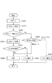
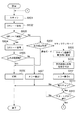
図3は、実施例1における画像処理装置10のコピー動作実行時のフローを示す。この処理は、画像処理装置10のCPU101が記憶装置109内部のプログラムを実行し、画像処理装置10の各部を制御することにより実現される。
FIG. 3 illustrates a flow when the
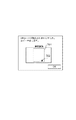
図2は、原稿台601に置かれた原稿20とスキャン領域602、QRコード検出領域603の例を示す図である。
受付部102でユーザから「コピースタートボタン」押下を受け付けると図3に示す処理が開始される。
CPU101は、原稿台401の原稿20をスキャンするようにスキャナ部104を制御し、原稿20を原稿画像として読み取る(ステップS301)。
CPU101は、読み取った原稿画像からQRコードを検出するようにコード検出部106を制御し、QRコードを検出する(ステップS302)。
CPU101は、QRコード検出結果に応じて、ステップS304、または、ステップS308の処理に移行する(ステップS303)。
ステップS303で原稿画像からQRコードが検出された場合、CPU101は、検出されたQRコードを復号するようにコード復号部107を制御する(ステップS304)。
FIG. 2 is a diagram illustrating an example of the
When the accepting
The
The
The
When a QR code is detected from the document image in step S303, the
コード復号部107でQRコードを復号した結果、出力許可原稿を示す情報が得られた場合、CPU101は、印刷部105を制御して原稿画像を印刷する(ステップS306)。
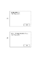
コード復号部107でQRコードを復号した結果、出力禁止原稿を示す情報が得られた場合、CPU101は、表示部103にエラー表示1を表示する(ステップS307)。
図4(A)に、エラー表示1の例を示す。図示する通り、出力禁止原稿でコピーを中止したことを表示する。
ステップS303で原稿画像からQRコードが検出されなかった場合、CPU101は、画像処理装置10に設定されている出力禁止設定を確認する(ステップS308)。
As a result of decoding the QR code by the
As a result of decoding the QR code by the
FIG. 4A shows an example of error display 1. As shown in the figure, it is displayed that copying has been canceled for an output-prohibited document.
If no QR code is detected from the document image in step S303, the
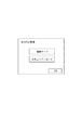
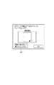
図5に、出力禁止設定の画面例を示す。図示する通り、出力禁止設定には標準モードとセキュリティモードがある。
標準モードとセキュリティモードとの違いは、QRコードが検出されなかった場合の動作の違いで、標準モードの場合は出力を許可、セキュリティモードの場合は出力を禁止する。なお出力禁止設定は予め管理者により画像処理装置10に設定されている。
再び図3のフローに戻って説明する。ステップS308で出力禁止設定が標準モードの場合、標準モードではQRコードが検出されなくても出力を許可するので、CPU101は、ステップS306に移行し、印刷部105を制御して原稿画像を印刷する。
ステップS308で出力禁止設定がセキュリティモードの場合、セキュリティモードではQRコードが検出されない場合出力を禁止するので、CPU101は、表示部103にエラー表示2を表示する(ステップS309)。
図4(B)に、エラー表示2の例を示す。図示する通り、原稿からQRコードが検出されずにコピーを中止したことを表示する。
以上のようにCPU101が画像処理装置10の各部を制御することで、原稿20に付加されたQRコード201が検出されずに出力禁止となった場合に、ユーザがその事由を知ることができるという効果が得られる。
FIG. 5 shows a screen example of output prohibition setting. As shown, the output prohibition setting includes a standard mode and a security mode.
The difference between the standard mode and the security mode is the difference in operation when no QR code is detected. Output is permitted in the standard mode and output is prohibited in the security mode. The output prohibition setting is set in advance in the
Returning to the flowchart of FIG. If the output prohibition setting is the standard mode in step S308, the output is permitted even if no QR code is detected in the standard mode. Therefore, the
If the output prohibition setting is the security mode in step S308, the output is prohibited if no QR code is detected in the security mode, so the
FIG. 4B shows an example of error display 2. As shown in the drawing, it is displayed that the copying is stopped without detecting the QR code from the document.
As described above, when the
実施例1では、QRコードが検出されずに出力禁止となったことをエラー表示でユーザに通知する例を示した。本実施例ではさらに読み取った原稿画像も同時に表示して、ユーザに出力禁止となった原因をより具体的に通知する例について説明する。
図6は、実施例2における画像処理装置10のコピー動作実行時のフローを示す。この処理は、画像処理装置10のCPU101が記憶装置109内部のプログラムを実行し、画像処理装置10の各部を制御することにより実現される。
図6のステップS601からS608までの処理は、図3のステップS301からS308の処理と同様であるため説明を省略する。
ステップS608で出力禁止設定がセキュリティモードの場合、CPU101は、スキャナ部104で読み取った原稿画像を画像処理部108で表示用に変換する(ステップS609)。さらに、CPU101は、この表示用画像にQRコード検出領域403を示す線を付加する(ステップS610)。
In the first embodiment, an example is shown in which the user is notified by an error display that the output is prohibited without detecting the QR code. In the present embodiment, an example will be described in which the read document image is also displayed at the same time to notify the user of the cause of the output prohibition more specifically.
FIG. 6 shows a flow when the
The processing from step S601 to S608 in FIG. 6 is the same as the processing from step S301 to S308 in FIG.
When the output prohibition setting is the security mode in step S608, the
続いてCPU101は、表示部103にエラー表示3を表示する(ステップS611)。
図7に、エラー表示3の例を示す。図示する通り、QRコードが検出されずにコピーを中止したことを表示するとともに、表示用の原稿画像701にQRコード検出領域を示す線702が付加された画像を表示する。
ユーザは、表示された画像を確認することで、例えば、QRコード検出領域に対して、QRコードの位置がずれてしまっているとか、QRコードが全く読み取られていないなど、QRコードが検出されなかった詳細原因を知ることができる。
Subsequently, the
FIG. 7 shows an example of the error display 3. As shown in the drawing, it is displayed that copying has been stopped without detecting a QR code, and an image in which a
By confirming the displayed image, the user can detect the QR code, for example, the QR code position is shifted from the QR code detection area or the QR code is not read at all. You can know the detailed cause that did not exist.
以上のように、原稿20に付加されたQRコード201が検出されずに出力禁止となった場合に、読み取った原稿画像も同時に表示することにより、ユーザがその事由をより具体的に知ることができるという効果が得られる。
As described above, when the
原稿のQRコードが検出されないケースには、初めから原稿にQRコードが付いていない場合と、付いているが原稿の置き方の問題でQRコードが正しく検出されないケースがある。後者の場合、原稿を正しく置き直して再度スキャンすれば、QRコードが検出される可能性がある。そこで実施例3では、QRコードが検出されずに出力禁止となった場合に、その旨通知するとともに、ユーザにやり直す手段を提供する例について説明する。 There are cases where the QR code of the original is not detected. There are cases where the QR code is not attached to the original from the beginning, and cases where the QR code is attached but is not correctly detected due to a problem of how to place the original. In the latter case, a QR code may be detected if the original is correctly placed and scanned again. Therefore, in the third embodiment, an example will be described in which when a QR code is not detected and output is prohibited, a notification to that effect is provided and a means for starting over is provided to the user.
図8は、実施例3における画像処理装置10のコピー動作実行時のフローを示す。この処理は、画像処理装置10のCPU101が記憶装置109内部のプログラムを実行し、画像処理装置10の各部を制御することにより実現される。
図8のステップS801からS810までの処理は、図6のステップS601からS608の処理と同様であるため説明を省略する。
FIG. 8 illustrates a flow when the
The processing from steps S801 to S810 in FIG. 8 is the same as the processing from steps S601 to S608 in FIG.
出力禁止設定がセキュリティモードで、原稿20に付加されたQRコード201が検出されずに出力禁止となった場合、CPU101は、表示部103にエラー表示4を表示する(ステップS811)。
図9にエラー表示4の例を示す。図示する通り、実施例2のエラー表示3(図9)に加えて、「原稿を置き直して再スキャンする」というボタンを表示する。
When the output prohibition setting is the security mode and the
FIG. 9 shows an example of the error display 4. As shown in the drawing, in addition to the error display 3 (FIG. 9) of the second embodiment, a button “Replace original and rescan” is displayed.
エラー表示4の画面で「再スキャンボタン」が押下されると、受付部102よりCPU101にその旨が入力され(ステップS812)、CPU101は、引き続き受付部102より「コピースタートボタン」押下が入力されるのを待機する(ステップS813)。
When the “rescan button” is pressed on the error display 4 screen, the fact is input to the
なお、エラー表示4の画面で「OK」ボタンが押下された場合は、CPU101は、この時点で一連の処理を終了する。
ユーザが原稿を置き直して「コピースタートボタン」を押下すると、受付部102よりCPU101にその旨が入力され、CPU101は、再びステップS801に戻って、原稿20のスキャンから処理を再開する。
以上のように、原稿20に付加されたQRコード201が検出されずに出力禁止となった場合に、ユーザに原稿を置き直して再スキャンする手段を提供することにより、より利便性の高い装置を提供することができる。
When the “OK” button is pressed on the error display 4 screen, the
When the user repositions the document and presses the “copy start button”, a message to that effect is input from the accepting
As described above, when the
(その他の実施例)
上記実施例では、スキャンした原稿画像の出力形態として印刷を例に説明したが、画像データとして出力を行う送信機能や記憶媒体への保存機能などで使用しても良い。
また、上記実施例において部分コードの例として二次元コードであるQRコードを使用したが、QRコードに限らず、STコード、バーコード、マークなど部分的にデジタル情報またはアナログ情報を付加できるものであればなにを使用してもかまわない。
また、本発明は、以下の処理を実行することによっても実現される。即ち、上述した実施形態の機能を実現するソフトウェア(プログラム)を、ネットワーク又は各種記憶媒体を介してシステム或いは装置に供給し、そのシステム或いは装置のコンピュータ(またはCPUやMPU等)がプログラムを読み出して実行する処理である。
(Other examples)
In the above embodiment, printing has been described as an example of the output form of the scanned original image. However, it may be used for a transmission function for outputting as image data, a storage function for a storage medium, or the like.
In the above embodiment, a QR code, which is a two-dimensional code, is used as an example of a partial code. However, the present invention is not limited to a QR code, and can partially add digital information or analog information such as an ST code, a barcode, or a mark. You can use whatever you want.
The present invention can also be realized by executing the following processing. That is, software (program) that realizes the functions of the above-described embodiments is supplied to a system or apparatus via a network or various storage media, and a computer (or CPU, MPU, or the like) of the system or apparatus reads the program. It is a process to be executed.
10 画像処理装置
20、21、22 原稿
201、202 QRコード
101 CPU
102 受付部
103 表示部
104 スキャナ部
105 印刷部
106 コード検出部
107 コード復号部
108 画像処理部
109 記憶装置
401 原稿台
402 スキャン領域
403 QRコード検出領域
10
DESCRIPTION OF
Claims (7)
コードを検出できない場合に、コードが検出できなかったが故にその画像データの出力を行わなかった旨を表示することを特徴とする装置。 An apparatus capable of performing settings for not outputting image data when a code cannot be detected from the image data,
An apparatus for displaying, when a code cannot be detected, that the image data was not output because the code could not be detected.
画像データからコードを検出できない場合に、その画像データの出力を行わない設定が行われていない場合には、前記表示を行わないことを特徴とする請求項1に記載の装置。 In this case, the display is performed only when the setting is made so as not to output the image data when the code cannot be detected from the image data.
2. The apparatus according to claim 1, wherein when the code cannot be detected from the image data, the display is not performed if the setting for not outputting the image data is not made.
コードを検出できない場合に、コードが検出できなかったが故にその画像データの印刷を行わなかった旨を表示することを特徴とする装置。 An apparatus that can perform a setting not to print the image data when a code cannot be detected from the image data,
An apparatus for displaying, when a code cannot be detected, that the image data was not printed because the code could not be detected.
コードを検出できない場合に、コードが検出できなかったが故にその画像データの出力を行わなかった旨を表示することを特徴とする装置の制御方法。 A method for controlling an apparatus capable of performing setting for not outputting image data when a code cannot be detected from the image data,
A control method for an apparatus, characterized in that, when a code cannot be detected, a message indicating that the image data was not output because the code could not be detected is displayed.
Priority Applications (1)
| Application Number | Priority Date | Filing Date | Title |
|---|---|---|---|
| JP2011002927A JP2012147162A (en) | 2011-01-11 | 2011-01-11 | Apparatus capable of detecting code, control method of apparatus, and program |
Applications Claiming Priority (1)
| Application Number | Priority Date | Filing Date | Title |
|---|---|---|---|
| JP2011002927A JP2012147162A (en) | 2011-01-11 | 2011-01-11 | Apparatus capable of detecting code, control method of apparatus, and program |
Publications (1)
| Publication Number | Publication Date |
|---|---|
| JP2012147162A true JP2012147162A (en) | 2012-08-02 |
Family
ID=46790300
Family Applications (1)
| Application Number | Title | Priority Date | Filing Date |
|---|---|---|---|
| JP2011002927A Pending JP2012147162A (en) | 2011-01-11 | 2011-01-11 | Apparatus capable of detecting code, control method of apparatus, and program |
Country Status (1)
| Country | Link |
|---|---|
| JP (1) | JP2012147162A (en) |
Cited By (1)
| Publication number | Priority date | Publication date | Assignee | Title |
|---|---|---|---|---|
| CN111588147A (en) * | 2020-05-25 | 2020-08-28 | 瑞信五金(河源)有限公司 | Quick detach watchband and wrist-watch |
-
2011
- 2011-01-11 JP JP2011002927A patent/JP2012147162A/en active Pending
Cited By (1)
| Publication number | Priority date | Publication date | Assignee | Title |
|---|---|---|---|---|
| CN111588147A (en) * | 2020-05-25 | 2020-08-28 | 瑞信五金(河源)有限公司 | Quick detach watchband and wrist-watch |
Similar Documents
| Publication | Publication Date | Title |
|---|---|---|
| US10149233B2 (en) | Communication apparatus, control method of communication apparatus, and storage medium | |
| JP2008283494A (en) | Image processing system | |
| JP5890667B2 (en) | Image processing apparatus, control method thereof, and program | |
| US8908219B2 (en) | Image forming apparatus including an automatic preview display print condition storage portion for storing preset print conditions | |
| JP5456015B2 (en) | A device capable of controlling output using a two-dimensional code, its control method, and program. | |
| KR20130076426A (en) | Image forming apparatus and method for displaying option screen thereof | |
| US20150261477A1 (en) | Image forming apparatus, method for controlling the same, and computer-readable storage medium | |
| JP2012147162A (en) | Apparatus capable of detecting code, control method of apparatus, and program | |
| JP5733989B2 (en) | Image duplicating apparatus, image duplicating method, information processing apparatus, and program | |
| JP2009100419A (en) | Image forming system and image forming apparatus | |
| JP6544637B2 (en) | INFORMATION PROCESSING APPARATUS, IMAGE READING APPARATUS, IMAGE FORMING APPARATUS, AND PROGRAM | |
| US10564907B2 (en) | Image forming apparatus, display control method, and storage medium | |
| JP2008245148A (en) | Document processing apparatus and control method thereof | |
| JP4797882B2 (en) | Image processing apparatus and image processing method | |
| US20130128296A1 (en) | Printing apparatus, method and program | |
| US9270851B2 (en) | Image forming apparatus method and storage medium storing program for controlling display when the image forming appratus returns to an active state from a power-saving state | |
| JP7314648B2 (en) | Information processing device, information processing method, and program | |
| JP2012244206A (en) | Image forming apparatus | |
| US10965832B2 (en) | Information processing apparatus saving fax transmission settings for redisplay | |
| JP2009105736A (en) | Image forming apparatus | |
| JP2017163258A (en) | Image processing method, program, image processing system, and image processing device | |
| JP2012070096A (en) | Image formation system, management device, and image formation device | |
| JP2017084183A (en) | Authentication system, terminal device, and program | |
| JP6446926B2 (en) | Image processing program and image processing apparatus | |
| JP2011082664A (en) | Image processor and image processing program |