JP2012146804A - Solar battery and manufacturing method of the same - Google Patents
Solar battery and manufacturing method of the same Download PDFInfo
- Publication number
- JP2012146804A JP2012146804A JP2011003733A JP2011003733A JP2012146804A JP 2012146804 A JP2012146804 A JP 2012146804A JP 2011003733 A JP2011003733 A JP 2011003733A JP 2011003733 A JP2011003733 A JP 2011003733A JP 2012146804 A JP2012146804 A JP 2012146804A
- Authority
- JP
- Japan
- Prior art keywords
- transparent electrode
- electrode layer
- solar cell
- layer
- zinc oxide
- Prior art date
- Legal status (The legal status is an assumption and is not a legal conclusion. Google has not performed a legal analysis and makes no representation as to the accuracy of the status listed.)
- Pending
Links
Images


Classifications
-
- Y—GENERAL TAGGING OF NEW TECHNOLOGICAL DEVELOPMENTS; GENERAL TAGGING OF CROSS-SECTIONAL TECHNOLOGIES SPANNING OVER SEVERAL SECTIONS OF THE IPC; TECHNICAL SUBJECTS COVERED BY FORMER USPC CROSS-REFERENCE ART COLLECTIONS [XRACs] AND DIGESTS
- Y02—TECHNOLOGIES OR APPLICATIONS FOR MITIGATION OR ADAPTATION AGAINST CLIMATE CHANGE
- Y02E—REDUCTION OF GREENHOUSE GAS [GHG] EMISSIONS, RELATED TO ENERGY GENERATION, TRANSMISSION OR DISTRIBUTION
- Y02E10/00—Energy generation through renewable energy sources
- Y02E10/50—Photovoltaic [PV] energy
- Y02E10/541—CuInSe2 material PV cells
-
- Y—GENERAL TAGGING OF NEW TECHNOLOGICAL DEVELOPMENTS; GENERAL TAGGING OF CROSS-SECTIONAL TECHNOLOGIES SPANNING OVER SEVERAL SECTIONS OF THE IPC; TECHNICAL SUBJECTS COVERED BY FORMER USPC CROSS-REFERENCE ART COLLECTIONS [XRACs] AND DIGESTS
- Y02—TECHNOLOGIES OR APPLICATIONS FOR MITIGATION OR ADAPTATION AGAINST CLIMATE CHANGE
- Y02P—CLIMATE CHANGE MITIGATION TECHNOLOGIES IN THE PRODUCTION OR PROCESSING OF GOODS
- Y02P70/00—Climate change mitigation technologies in the production process for final industrial or consumer products
- Y02P70/50—Manufacturing or production processes characterised by the final manufactured product
Landscapes
- Photovoltaic Devices (AREA)
Abstract
Description
本発明は、太陽電池及びその製造方法に関するものである。 The present invention relates to a solar cell and a manufacturing method thereof.
従来、基板上に裏面電極、光吸収層、透明電極がこの順に積層された薄膜型太陽電池が知られている。前記裏面電極、光吸収層、透明電極の各層は、例えば、スパッタリング等により、前記基板上に形成される。前記薄膜型太陽電池は、カバーガラスとバックシートとにより画成される空間に、前記透明電極を該カバーガラスに対向させて配設され、該カバーガラス及びバックシートとの間隙はエチレン−酢酸ビニル(EVA)樹脂等の封止剤により封止される。 Conventionally, a thin film solar cell in which a back electrode, a light absorption layer, and a transparent electrode are laminated in this order on a substrate is known. Each layer of the back electrode, the light absorption layer, and the transparent electrode is formed on the substrate by, for example, sputtering. The thin-film solar cell is disposed in a space defined by a cover glass and a back sheet with the transparent electrode facing the cover glass, and a gap between the cover glass and the back sheet is ethylene-vinyl acetate. (EVA) Sealed with a sealing agent such as resin.
前記薄膜型太陽電池では、前記カバーガラス側から前記透明電極を介して入射する前記光吸収層を形成するSi半導体、化合物半導体等の半導体により光電変換されることにより起電力を得ることができる。ここで、前記透明電極として、インジウムスズ酸化物(ITO)に比較して低コストであり製膜温度を低くできることから、アルミニウムドープ酸化亜鉛(AZO)を用いることが検討されている。 In the thin-film solar cell, an electromotive force can be obtained by photoelectric conversion by a semiconductor such as a Si semiconductor or a compound semiconductor that forms the light absorption layer incident from the cover glass side through the transparent electrode. Here, the use of aluminum-doped zinc oxide (AZO) has been studied as the transparent electrode because it is less expensive than indium tin oxide (ITO) and the film-forming temperature can be lowered.
ところが、前記AZO電極は、屈折率が2.0程度であり、前記カバーガラス及びEVA樹脂の屈折率が1.5程度であるのに比較して大きいという問題がある。この結果、前記AZO電極と前記封止剤としてのEVA樹脂との界面で入射光の反射が生じやすく、前記光吸収層に入射する光線が低減して十分な起電力を得られないことがある。 However, the AZO electrode has a problem that the refractive index is about 2.0, which is larger than the refractive indexes of the cover glass and EVA resin are about 1.5. As a result, incident light is likely to be reflected at the interface between the AZO electrode and the EVA resin as the sealant, and the light incident on the light absorption layer may be reduced, and a sufficient electromotive force may not be obtained. .
そこで、前記AZO電極と前記EVA樹脂との間に両者の中間の屈折率を備える反射防止層を配設し、入射光の反射を低減することにより、より大きな起電力を得られるようにすることが考えられる。前記反射防止層の材料としては、例えば、屈折率が1.70であるSiO、屈折率が1.75であるMgO等の無機酸化物が知られている(例えば特許文献1参照)。 Therefore, an anti-reflection layer having an intermediate refractive index between the AZO electrode and the EVA resin is disposed to reduce reflection of incident light so that a larger electromotive force can be obtained. Can be considered. As the material of the antireflection layer, for example, SiO having a refractive index of 1.70 and inorganic oxides such as MgO having a refractive index of 1.75 are known (for example, see Patent Document 1).
しかしながら、前記AZO電極上に前記SiO又はMgOからなる反射防止層を形成するには、前記AZOとは異種の材料によるスパッタリングを行わねばならないので、異種のそれぞれの材料に合わせて製膜条件を変更しなければならないという不都合がある。 However, in order to form the antireflection layer made of SiO or MgO on the AZO electrode, it is necessary to perform sputtering using a material different from that of the AZO. Therefore, the film forming conditions are changed according to each different material. There is an inconvenience that must be done.
そこで、本発明は、かかる不都合を解消して、製造が容易で、光透過性を損なうことなく透明電極とカバーガラス又はEVA樹脂との界面における入射光の反射を低減することができる太陽電池及びその製造方法を提供することを目的とする。 Therefore, the present invention eliminates such inconvenience, is easy to manufacture, and can reduce the reflection of incident light at the interface between the transparent electrode and the cover glass or EVA resin without impairing the light transmittance, and It aims at providing the manufacturing method.
本発明者らは、AZOの屈折率と光透過性との関係について検討した。この結果、AZOのアルミニウム含有量を、通常の透明電極として用いられるAZOよりも高い特定の範囲とすることにより、光透過性を低減させることなく、屈折率を通常の透明電極として用いられるAZOよりも小さくすることができることを見出し、本発明に到達した。 The inventors examined the relationship between the refractive index of AZO and the light transmittance. As a result, by setting the aluminum content of AZO to a specific range higher than that of AZO used as a normal transparent electrode, the refractive index is lower than that of AZO used as a normal transparent electrode without reducing light transmittance. And the present invention has been reached.
そこで、本発明の太陽電池は、前記目的を達成するために、基板上に、裏面電極層と、入射した光線を光電変換して起電力を得る光吸収層と、アルミニウムドープ酸化亜鉛からなる透明電極層とを備える太陽電池において、該透明電極層は、該光吸収層との界面側よりも該界面から離間する側のアルミニウム含有量が多いことを特徴とする。 Therefore, in order to achieve the above object, the solar cell of the present invention is a transparent electrode composed of a back electrode layer, a light absorption layer that photoelectrically converts incident light to obtain an electromotive force, and aluminum-doped zinc oxide. In a solar cell comprising an electrode layer, the transparent electrode layer is characterized in that the aluminum content on the side away from the interface is higher than that on the interface side with the light absorption layer.
本発明の太陽電池によれば、前記アルミニウムドープ酸化亜鉛からなる透明電極層の前記光吸収層との界面側から離間する側、即ち外層側のアルミニウム含有量を多くすることにより、この部分の屈折率が該光吸収層との界面側よりも小さくなる。この結果、本発明の太陽電池をカバーガラスとバックシートとにより画成される空間に、前記透明電極層を該カバーガラスに対向させて配設し、該カバーガラス及びバックシートとの間隙をEVA樹脂等の封止剤により封止したときに、該カバーガラス及びEVA樹脂と該透明電極層との屈折率の差が小さくなり、反射光を低減することができる。 According to the solar cell of the present invention, the portion of the transparent electrode layer made of aluminum-doped zinc oxide that is separated from the interface side with the light absorption layer, that is, the aluminum content on the outer layer side is increased to increase the refraction of this portion. The rate is smaller than the interface side with the light absorption layer. As a result, the solar cell of the present invention is disposed in a space defined by the cover glass and the back sheet so that the transparent electrode layer faces the cover glass, and the gap between the cover glass and the back sheet is EVA. When sealed with a sealant such as resin, the difference in refractive index between the cover glass and EVA resin and the transparent electrode layer is reduced, and reflected light can be reduced.
本発明の太陽電池において、前記透明電極層は、前記光吸収層との界面側から離間する側に向かって連続的にアルミニウム含有量が増加するようにしてもよく、アルミニウム含有量が互いに異なる複数の層からなり、各層のアルミニウム含有量を、前記光吸収層との界面側よりも該界面から離隔する側の方で多くするようにしてもよい。 In the solar cell of the present invention, the transparent electrode layer may be configured such that the aluminum content continuously increases from the interface side with the light absorption layer toward the side away from the light absorption layer, and a plurality of aluminum contents different from each other. The aluminum content of each layer may be increased on the side farther from the interface than on the interface with the light absorption layer.
本発明の太陽電池において、前記透明電極層がアルミニウム含有量が互いに異なる複数の層からなるとき、前記透明電極層は、例えば、前記光吸収層上に積層された第1の透明電極層と、第1の透明電極層上に積層され第1の透明電極層よりもアルミニウム含有量が多い第2の透明電極層とからなるようにすることができる。このとき、前記第1の透明電極層はアルミニウム含有量が第1の透明電極層全体の2質量%以下の範囲であり、前記第2の透明電極層はアルミニウム含有量が第2の透明電極層全体の3.0〜5.0質量%の範囲であることが好ましい。 In the solar cell of the present invention, when the transparent electrode layer is composed of a plurality of layers having different aluminum contents, the transparent electrode layer includes, for example, a first transparent electrode layer laminated on the light absorption layer; It can be made to consist of a 2nd transparent electrode layer laminated | stacked on a 1st transparent electrode layer and having much aluminum content rather than a 1st transparent electrode layer. At this time, the first transparent electrode layer has an aluminum content of 2% by mass or less of the entire first transparent electrode layer, and the second transparent electrode layer has an aluminum content of the second transparent electrode layer. It is preferable that it is the range of 3.0-5.0 mass% of the whole.
前記第2の透明電極層は、アルミニウム含有量が前記範囲であることにより、前記第1の透明電極層よりも屈折率を小さくすることができる。前記第2の透明電極層は、アルミニウム含有量が第2の透明電極層全体の3.0質量%未満では、その屈折率を前記第1の透明電極層に対して十分に小さくすることができないことがある。また、前記第2の透明電極層は、アルミニウム含有量が第2の透明電極層全体の5.0質量%を超えると十分な光透過性を得ることができないことがある。 The second transparent electrode layer can have a refractive index smaller than that of the first transparent electrode layer when the aluminum content is in the above range. The refractive index of the second transparent electrode layer cannot be made sufficiently small with respect to the first transparent electrode layer when the aluminum content is less than 3.0 mass% of the entire second transparent electrode layer. Sometimes. Further, the second transparent electrode layer may not be able to obtain sufficient light transmittance when the aluminum content exceeds 5.0 mass% of the entire second transparent electrode layer.
本発明の太陽電池は、基板上に裏面電極層を形成する工程と、該裏面電極層上に入射した光線を光電変換して起電力を得る光吸収層を形成する工程と、該光吸収層上にアルミニウムを含む酸化亜鉛ターゲットを用いるスパッタリングによりアルミニウムドープ酸化亜鉛からなる透明電極層を形成する工程とを備える太陽電池の製造方法において、該スパッタリングは、アルミニウム含有量が互いに異なる複数の酸化亜鉛ターゲットを用い、同一の製膜条件下、酸化亜鉛ターゲットをアルミニウム含有量が少ないものから多いものに順次交換して行う製造方法により製造することができる。 The solar cell of the present invention includes a step of forming a back electrode layer on a substrate, a step of forming a light absorption layer that obtains an electromotive force by photoelectrically converting light incident on the back electrode layer, and the light absorption layer And a step of forming a transparent electrode layer made of aluminum-doped zinc oxide by sputtering using a zinc oxide target containing aluminum, wherein the sputtering includes a plurality of zinc oxide targets having different aluminum contents. Can be manufactured by a manufacturing method in which the zinc oxide target is sequentially changed from one having a low aluminum content to one having a high aluminum content under the same film forming conditions.
本発明の製造方法によれば、前記アルミニウムドープ酸化亜鉛からなる透明電極層を形成する工程において、アルミニウム含有量が互いに異なる複数の酸化亜鉛ターゲットをアルミニウム含有量が少ないものから多いものに順次交換することにより、前記光吸収層との界面側よりも該界面から離間する側のアルミニウム含有量が多い前記透明電極層を形成することができる。本発明の製造方法によれば、いずれのターゲットも同種の酸化亜鉛であるため、スパッタリングの条件を変化させず同一の製膜条件下でアルミニウム含有量の異なる層を製造することができるので、本発明の太陽電池を容易に製造することができる。 According to the production method of the present invention, in the step of forming the transparent electrode layer made of aluminum-doped zinc oxide, a plurality of zinc oxide targets having different aluminum contents are sequentially replaced from those having a lower aluminum content to those having a higher aluminum content. Thus, the transparent electrode layer having a higher aluminum content on the side away from the interface than on the interface with the light absorption layer can be formed. According to the production method of the present invention, since any target is the same type of zinc oxide, layers having different aluminum contents can be produced under the same film-forming conditions without changing the sputtering conditions. The solar cell of the invention can be easily manufactured.
本発明の製造方法において、前記スパッタリングは、所定のアルミニウムを含有する第1の酸化亜鉛ターゲットを用いて第1の透明電極層を形成した後、同一の製膜条件下、第1の酸化亜鉛ターゲットよりアルミニウム含有量が多い第2の酸化亜鉛ターゲットを用いて第1の透明電極層上に第2の透明電極層を形成することが好ましい。このようにすることにより、前記光吸収層上に積層された第1の透明電極層と、第1の透明電極層上に積層され第1の透明電極層よりもアルミニウム含有量が多い第2の透明電極層とからなる前記透明電極層を容易に形成することができる。 In the manufacturing method of the present invention, the sputtering uses the first zinc oxide target containing predetermined aluminum to form the first transparent electrode layer, and then the first zinc oxide target under the same film forming conditions. It is preferable to form the second transparent electrode layer on the first transparent electrode layer using a second zinc oxide target having a higher aluminum content. By doing in this way, the 1st transparent electrode layer laminated on the above-mentioned light absorption layer, and the 2nd higher aluminum content than the 1st transparent electrode layer laminated on the 1st transparent electrode layer The transparent electrode layer composed of the transparent electrode layer can be easily formed.
次に、添付の図面を参照しながら本発明の実施の形態についてさらに詳しく説明する。 Next, embodiments of the present invention will be described in more detail with reference to the accompanying drawings.
図1(a)に示すように、本実施形態の太陽電池1は、ガラス基板2上に裏面電極層3、光吸収層4、透明電極層5がこの順に積層されている。太陽電池1は、図1(b)に示すように、カバーガラス6とバックシート7とにより画成される空間内に配設されて太陽電池モジュール8を形成している。太陽電池モジュール8において、太陽電池1は透明電極5がカバーガラス6に対向するように配置され、太陽電池1とカバーガラス6及びバックシート7との間隙にはエチレン−酢酸ビニル(EVA)樹脂等の封止剤9が充填され、太陽電池1が封止されている。
As shown to Fig.1 (a), the
太陽電池1において、裏面電極層3は例えばMo等からなり、光吸収層4は例えば化学式Cu(InGa)Se2で表されるカルコパイライト化合物(CIGS)等からなり、入射した光線を光電変換して起電力を得ることができる。また、光吸収層4は表面に図示しないバッファ層を備えている。前記バッファ層は例えばInS等からなる。
In the
本実施形態の太陽電池1において、透明電極層5はアルミニウムドープ酸化亜鉛(AZO)からなる。このとき、透明電極層5は、光吸収層4との界面側の部分ではアルミニウム含有量が少なく、該界面から離間する側の部分ではアルミニウム含有量が多くなっている。
In the
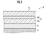
このような透明電極層5は、例えば、図2に示すように、光吸収層4上に積層された第1の透明電極層5aと、第1の透明電極層5a上に積層され第1の透明電極層5aよりもアルミニウム含有量が多い第2の透明電極層5bとから構成することができる。尚、図2では封止剤9を省略して示している。
Such a
第1の透明電極層5aは、例えばアルミニウム含有量が2.0質量%のAZOからなり、屈折率が2.0である。一方、第2の透明電極層5bは、アルミニウム含有量が3.0〜5.0質量%の範囲のAZOからなることにより、屈折率を1.70〜1.80の範囲とすることができる。
The first transparent electrode layer 5a is made of, for example, AZO having an aluminum content of 2.0% by mass and has a refractive index of 2.0. On the other hand, the second
ここで、太陽電池モジュール8では、カバーガラス6の屈折率は1.5程度であり、封止剤9の屈折率もカバーガラス6と同程度である。そこで、透明電極層5を第1の透明電極層5a及び第2の透明電極層5bから構成することにより、アルミニウム含有量が2.0質量%のAZOのみから構成する場合に比較して、カバーガラス6及び封止剤9との屈折率の差を小さくすることができる。従って、太陽電池1によれば、太陽電池モジュール8としたときに、カバーガラス6及び封止剤9(図2ではカバーガラス6で代表させている)との界面での反射光を低減することができる。
Here, in the solar cell module 8, the refractive index of the cover glass 6 is about 1.5, and the refractive index of the sealant 9 is also about the same as that of the cover glass 6. Therefore, by forming the
また、第2の透明電極層5bはアルミニウム含有量が3.0〜5.0質量%の範囲のAZOからなることにより、光透過性を損なうことがない。従って、本実施形態の太陽電池1によれば、光吸収層4における光電変換効率を1%以上向上させることができる。
Further, the second
また、AZOの光透過性は膜厚にも関係があり、第2の透明電極層5bは60〜150nmの範囲の膜厚を備えていることが好ましい。第2の透明電極層5bの膜厚が前記範囲外であるときには、光吸収層4における光電変換効率を1%以上向上させる効果が得られないことがある。
The light transmittance of AZO is also related to the film thickness, and the second
尚、図2に示す構成では、透明電極層5を、アルミニウム含有量が2.0質量%のAZOからなり屈折率が2.0の第1の透明電極層5aと、アルミニウム含有量が3.0〜5.0質量%のAZOからなり、屈折率が1.70〜1.80の範囲の第2の透明電極層5bとの2層により構成している。しかし、透明電極層5は3層以上の層から構成し、光吸収層4側からカバーガラス6に対向する側に向かって、各層のアルミニウム含有量が段階的に増加するようにしてもよい。また、透明電極層5を単一の層とし、光吸収層4側からカバーガラス6に対向する側に向かって連続的にアルミニウム含有量が多くなる構成としてもよい。
In the configuration shown in FIG. 2, the
次に、図1及び図2に示す太陽電池1の製造方法について説明する。
Next, the manufacturing method of the
太陽電池モジュール8を製造するときには、まず、ガラス基板2上に、Moからなる裏面電極3をスパッタリングし、レーザーを照射してスクライブすることにより、複数の領域に分割する。次に、分割された裏面電極4上に、Cu・Ga層をスパッタリングし、さらにCu・Ga層上にIn層をスパッタリングする。
When manufacturing the solar cell module 8, first, the back electrode 3 made of Mo is sputtered on the
次に、ガラス基板2をH2Seガス雰囲気中、例えば400〜600℃の範囲の温度に加熱し、Cu・Ga/In層をSe化することによりCIGSとする。次に、CIGS層上に化学浴堆積法によりInSからなるバッファ層を形成し、CIGS層とバッファ層とからなる光吸収層4を形成する。そして、光吸収層4をニードルによりスクライブして、分割された裏面電極3に対応する複数の領域に分割する。
Next, the
次に、光吸収層4上に、スパッタリングによりAZOからなる透明電極5を形成する。ここで透明電極5が、第1の透明電極5aと第2の透明電極5bとからなるときには、まず、2.0質量%のAlを含む酸化亜鉛ターゲットを用いてスパッタリングを行い、光吸収層4上に第1の透明電極5aを所定の厚さ、例えば520nmの厚さに形成する。次に、前記酸化亜鉛ターゲットを3.0〜5.0質量%のAlを含む酸化亜鉛ターゲットに交換し、第1の透明電極5aの形成時と同一の製膜条件でスパッタリングを行うことにより、第1の透明電極5a上に第2の透明電極5bを60〜155nmの厚さ、例えば80nmの厚さに形成する。
Next, the
この結果、本実施形態の太陽電池1を製造することができる。太陽電池1は、カバーガラス6とバックシート7とにより画成される空間に配設したのち、常法により、EVA樹脂等の封止剤9により封止されることにより、太陽電池モジュール8を形成することができる。
As a result, the
次に、アルミニウム含有量が2.0質量%のAZOからなり屈折率が2.0、膜厚が520nmの第1の透明電極層5a上に、第2の透明電極層5bを形成した太陽電池1を用いて太陽電池モジュール8を形成し、光吸収層4の光電変換効率を測定した。ここで、第2の透明電極層5bはAZOのアルミニウム含有量を3.0〜5.0質量%の範囲で変量することにより、屈折率が1.70〜1.80の範囲で変量するようにした。また、各屈折率の第2の透明電極層5bに対し、膜厚を61〜151nmの範囲で変量した。
Next, a solar cell in which the second
透明電極5が、アルミニウム含有量が2.0質量%のAZOからなり屈折率が2.0、膜厚が600nmの第1の透明電極層5aのみからなるときの光吸収層4の光電変換効率を100として、結果を図3に示す。
Photoelectric conversion efficiency of the light absorption layer 4 when the
図3から、本実施形態の太陽電池1によれば、前記第1の透明電極層5a上に、アルミニウム含有量が3.0〜5.0質量%のAZOからなり屈折率が1.70〜1.80、膜厚が61〜151nmの第2の透明電極層5bを形成することにより、光吸収層4の光電変換効率を1%以上向上している。従って、第2の透明電極層5bにより、カバーガラス6及び封止剤9と透明電極層5との界面における入射光の反射を低減することができると共に、第2の透明電極層5bの光透過性が損なわれていないことが明らかである。
From FIG. 3, according to the
1…太陽電池、 2…ガラス基板、 3…裏面電極層、 4…光吸収層、 5…透明電極層、 5a…第1の透明電極層、 5b…第2の透明電極層。
DESCRIPTION OF
Claims (6)
該透明電極層は、該光吸収層との界面側よりも該界面から離間する側のアルミニウム含有量が多いことを特徴とする太陽電池。 On a substrate, a solar cell comprising a back electrode layer, a light absorption layer that photoelectrically converts incident light to obtain an electromotive force, and a transparent electrode layer made of aluminum-doped zinc oxide,
The solar cell, wherein the transparent electrode layer has a higher aluminum content on the side away from the interface than on the interface with the light absorption layer.
該裏面電極層上に入射した光線を光電変換して起電力を得る光吸収層を形成する工程と、
該光吸収層上にアルミニウムを含む酸化亜鉛ターゲットを用いるスパッタリングによりアルミニウムドープ酸化亜鉛からなる透明電極層を形成する工程とを備える太陽電池の製造方法において、
該スパッタリングは、アルミニウム含有量が互いに異なる複数の酸化亜鉛ターゲットを用い、同一の製膜条件下、酸化亜鉛ターゲットをアルミニウム含有量が少ないものから多いものに順次交換して行うことを特徴とする太陽電池の製造方法。 Forming a back electrode layer on the substrate;
Forming a light absorbing layer that photoelectrically converts light incident on the back electrode layer to obtain an electromotive force; and
And a step of forming a transparent electrode layer made of aluminum-doped zinc oxide by sputtering using a zinc oxide target containing aluminum on the light absorption layer.
The sputtering is performed by using a plurality of zinc oxide targets having different aluminum contents and sequentially changing the zinc oxide target from one having a low aluminum content to one having a high aluminum content under the same film-forming conditions. Battery manufacturing method.
Priority Applications (1)
| Application Number | Priority Date | Filing Date | Title |
|---|---|---|---|
| JP2011003733A JP2012146804A (en) | 2011-01-12 | 2011-01-12 | Solar battery and manufacturing method of the same |
Applications Claiming Priority (1)
| Application Number | Priority Date | Filing Date | Title |
|---|---|---|---|
| JP2011003733A JP2012146804A (en) | 2011-01-12 | 2011-01-12 | Solar battery and manufacturing method of the same |
Publications (1)
| Publication Number | Publication Date |
|---|---|
| JP2012146804A true JP2012146804A (en) | 2012-08-02 |
Family
ID=46790088
Family Applications (1)
| Application Number | Title | Priority Date | Filing Date |
|---|---|---|---|
| JP2011003733A Pending JP2012146804A (en) | 2011-01-12 | 2011-01-12 | Solar battery and manufacturing method of the same |
Country Status (1)
| Country | Link |
|---|---|
| JP (1) | JP2012146804A (en) |
Citations (2)
| Publication number | Priority date | Publication date | Assignee | Title |
|---|---|---|---|---|
| JPH10144946A (en) * | 1996-11-08 | 1998-05-29 | Showa Shell Sekiyu Kk | Transparent conductive film of thin-film solar cell and its manufacture |
| JP2000091603A (en) * | 1998-09-07 | 2000-03-31 | Honda Motor Co Ltd | Solar battery |
-
2011
- 2011-01-12 JP JP2011003733A patent/JP2012146804A/en active Pending
Patent Citations (2)
| Publication number | Priority date | Publication date | Assignee | Title |
|---|---|---|---|---|
| JPH10144946A (en) * | 1996-11-08 | 1998-05-29 | Showa Shell Sekiyu Kk | Transparent conductive film of thin-film solar cell and its manufacture |
| JP2000091603A (en) * | 1998-09-07 | 2000-03-31 | Honda Motor Co Ltd | Solar battery |
Similar Documents
| Publication | Publication Date | Title |
|---|---|---|
| KR101000057B1 (en) | Solar Cell Having Multiple Transparent Conducting Layers And Manufacturing Method Thereof | |
| KR20160112022A (en) | Multilayer component for the encapsulation of a sensitive element | |
| KR101072204B1 (en) | Solar cell and method of fabricating the same | |
| CN103765606A (en) | Thin film solar cell and manufacturing method therefor | |
| WO2012018199A3 (en) | Silicon multilayer anti-reflective film with gradually varying refractive index and manufacturing method therefor, and solar cell having same and manufacturing method therefor | |
| CN102005485A (en) | Multilayer anti-reflection film for solar cell and preparation method thereof | |
| JP2014033202A (en) | Thin film solar cell module and method of manufacturing the same | |
| JP2008270562A (en) | Multi-junction type solar cell | |
| EP2273559A1 (en) | Solar cell | |
| KR101814821B1 (en) | Solar cell module | |
| CN105023958A (en) | CIGS (Copper Indium Gallium Selenide)-based thin-film solar cell and manufacturing method thereof | |
| JP2017059656A (en) | Photoelectric conversion element and solar battery | |
| JP2012146804A (en) | Solar battery and manufacturing method of the same | |
| TW201445748A (en) | Colored solar cells and panels containing the same | |
| US20100319772A1 (en) | Thin film solar cell with light transmission | |
| CN102856421A (en) | Novel three-junction thin-film solar cell and production method thereof | |
| CN104659118A (en) | Multi-layered anti-reflecting film for solar cells | |
| CN102931242A (en) | Crystalline silicon solar cell multi-layer silica dioxide antireflection film | |
| CN102270672A (en) | Multilayer back reflector structure used for thin-film solar cell | |
| JP5542038B2 (en) | Thin film solar cell and method for manufacturing the same, thin film solar cell module | |
| TWI415278B (en) | Multi-layered thin-film solar cell | |
| CN105261666A (en) | Thin-film solar cell | |
| US20140299180A1 (en) | Multi-junction photovoltaic modules incorporating ultra-thin flexible glass | |
| TWI614910B (en) | Photovoltaic conversion module | |
| JP2007251114A (en) | Substrate for high-performance solar cell having optical multi-layer film, and manufacturing method therefor |
Legal Events
| Date | Code | Title | Description |
|---|---|---|---|
| A621 | Written request for application examination |
Free format text: JAPANESE INTERMEDIATE CODE: A621 Effective date: 20131127 |
|
| A977 | Report on retrieval |
Free format text: JAPANESE INTERMEDIATE CODE: A971007 Effective date: 20140306 |
|
| A131 | Notification of reasons for refusal |
Free format text: JAPANESE INTERMEDIATE CODE: A131 Effective date: 20140909 |
|
| A521 | Request for written amendment filed |
Free format text: JAPANESE INTERMEDIATE CODE: A523 Effective date: 20141106 |
|
| A02 | Decision of refusal |
Free format text: JAPANESE INTERMEDIATE CODE: A02 Effective date: 20141125 |