JP2012146523A - Retainer mounting structure - Google Patents
Retainer mounting structure Download PDFInfo
- Publication number
- JP2012146523A JP2012146523A JP2011004160A JP2011004160A JP2012146523A JP 2012146523 A JP2012146523 A JP 2012146523A JP 2011004160 A JP2011004160 A JP 2011004160A JP 2011004160 A JP2011004160 A JP 2011004160A JP 2012146523 A JP2012146523 A JP 2012146523A
- Authority
- JP
- Japan
- Prior art keywords
- connector housing
- retainer
- positioning
- lance
- mounting structure
- Prior art date
- Legal status (The legal status is an assumption and is not a legal conclusion. Google has not performed a legal analysis and makes no representation as to the accuracy of the status listed.)
- Granted
Links
Images


Abstract
Description
本発明は、リテーナの取付構造に関する。 The present invention relates to a retainer mounting structure.
従来、相手側端子を収容するキャビティが複数設けられたコネクタハウジングを有するコネクタとして、例えば下記特許文献1に記載のものが知られている。キャビティの内壁には、キャビティに収容された相手側端子を抜け止めするランスが設けられている。このランスは、コネクタハウジングの外面とキャビティの内壁との間にスリットを形成することでコネクタハウジングの外面側に弾性撓み可能とされており、コネクタハウジングの外部に面した配置とされている。 Conventionally, as a connector having a connector housing provided with a plurality of cavities for accommodating mating terminals, for example, a connector described in Patent Document 1 below is known. A lance is provided on the inner wall of the cavity to prevent the mating terminal housed in the cavity from coming off. The lance can be elastically bent toward the outer surface side of the connector housing by forming a slit between the outer surface of the connector housing and the inner wall of the cavity, and is arranged to face the outside of the connector housing.
しかしながら、上記のコネクタにおいてはランスとともに相手側端子を二重に抜け止めするリテーナの取付構造が元々設定されておらず、相手側端子に連なる電線が強く引っ張られるなどしてランスによる係止力だけでは不足する場合も起こりうる。このように、さらなる係止力が必要とされる場合でも後からリテーナを追加することはできないため、柔軟な対応をとることができなかった。 However, in the above connector, the retainer mounting structure that double-stops the mating terminal together with the lance is not originally set, and only the locking force by the lance is obtained, for example, the wire connected to the mating terminal is pulled strongly. Then there may be a shortage. As described above, even when a further locking force is required, a retainer cannot be added later, so that a flexible response cannot be taken.
本発明は上記のような事情に基づいて完成されたものであって、係止力を向上させるべく、後からリテーナを追加できるようにすることを目的とする。 The present invention has been completed based on the above circumstances, and an object thereof is to allow a retainer to be added later in order to improve the locking force.
本発明は、前後方向に貫通する形態をなして左右方向に並んだ複数のキャビティを有し、このキャビティに収容された相手側端子を抜け止めするランスがキャビティ毎に設けられたコネクタハウジングと、このコネクタハウジングの内部に装着され、キャビティに収容された相手側端子同士を短絡させるジョイント端子とを備えたコネクタにおいて、ランスは、コネクタハウジングの外面における一側の面とキャビティの内壁との間に設けられかつ一側に撓み可能とされ、コネクタハウジングに、ランスの一側への変位を規制するリテーナが装着可能とされたリテーナの取付構造であって、リテーナは、コネクタハウジングの左右方向両側に配設されてコネクタハウジングの外面における他側の面に係止することで一側への脱落を規制する一対のロック部と、コネクタハウジングの外面における一側の面に形成された係止凹部と係止することで前後方向および左右方向の位置決めを行う複数の位置決め凸部とを備えている構成としたところに特徴を有する。 The present invention includes a connector housing having a plurality of cavities arranged in the left-right direction in a form penetrating in the front-rear direction, and a lance that is provided for each cavity to prevent the mating terminal accommodated in the cavity from coming off. In the connector that is mounted inside the connector housing and includes a joint terminal that short-circuits the mating terminals housed in the cavity, the lance is between the one side surface on the outer surface of the connector housing and the inner wall of the cavity. A retainer mounting structure that is provided and can be deflected to one side, and that can be attached to the connector housing to restrict displacement to one side of the lance. The retainer is provided on both sides of the connector housing in the left-right direction. One that regulates falling off to one side by being disposed and locked to the other side of the outer surface of the connector housing And a plurality of positioning projections for positioning in the front-rear direction and the left-right direction by engaging with a locking recess formed on one surface of the outer surface of the connector housing. It has the characteristics.
このような構成によると、コネクタにリテーナの取付構造が元々設定されていない場合においても、コネクタ側にリテーナを取り付けるための特別な取付構造を必要としないため、後からでもリテーナを追加することができる。すなわち、両ロック部によってリテーナがコネクタハウジングから脱落することを規制し、係止凹部に位置決め凸部を係止させることでリテーナの前後方向および左右方向の位置決めを行うことができる。 According to such a configuration, even when the retainer mounting structure is not originally set in the connector, a special mounting structure for mounting the retainer on the connector side is not required, so that the retainer can be added later. it can. That is, it is possible to position the retainer in the front-rear direction and the left-right direction by restricting the retainer from falling off the connector housing by both lock portions and locking the positioning convex portion in the locking recess.
本発明の実施の態様として、以下の構成が好ましい。
係止凹部は、コネクタハウジングにおけるランスの前側と左右両側とに切り欠き形成されてなる周溝によって構成され、周溝におけるランスの左右両側部分に、位置決め凸部が挿入される構成としてもよい。
このような構成によると、係止凹部がランスの周溝によって構成されているため、コネクタハウジングの構成を簡素化できる。
The following configuration is preferable as an embodiment of the present invention.
The locking recess may be formed by a circumferential groove formed by notching the front side of the lance and the left and right sides of the connector housing, and the positioning projections may be inserted into the left and right side portions of the lance in the circumferential groove.
According to such a structure, since the latching recessed part is comprised by the circumferential groove of the lance, the structure of a connector housing can be simplified.
両ロック部は、コネクタハウジングの左右方向両側面に沿って配設され、リテーナを左右方向に位置決めしている構成としてもよい。
このような構成によると、両ロック部がコネクタハウジングの両側面と係止することで、リテーナの左右方向の位置決めを行うことができる。
Both lock portions may be arranged along both left and right side surfaces of the connector housing, and the retainer may be positioned in the left and right direction.
According to such a configuration, the retainer can be positioned in the left-right direction by engaging the both lock portions with both side surfaces of the connector housing.
位置決め凸部は、前後方向に延びる形態をなす位置決めリブの前後両端部からなる構成としてもよい。
このような構成によると、前後一対の位置決め凸部を位置決めリブとして一体に設けることができるため、両位置決め凸部の強度を増すことができる。
The positioning convex portion may be configured by both front and rear end portions of a positioning rib having a form extending in the front-rear direction.
According to such a configuration, since the pair of front and rear positioning convex portions can be integrally provided as positioning ribs, the strength of both positioning convex portions can be increased.
コネクタハウジングの両側壁が、左右両端に位置する位置決めリブとこれに対向するロック部との間にそれぞれ配置されることで、リテーナの左右方向の位置決めをさらに行う構成としてもよい。
このような構成によると、左右両端に位置する両位置決めリブと両ロック部によってリテーナの左右方向の位置決めを確実に行うことができる。
It is good also as a structure which further positions the retainer in the left-right direction by arrange | positioning both the side walls of a connector housing between the positioning rib located in the right-and-left both ends, and the lock part facing this, respectively.
According to such a structure, the positioning of the retainer in the left-right direction can be reliably performed by the positioning ribs and the lock portions positioned at both the left and right ends.
方形状をなすキャビティにおける対角をなす位置には、相手側端子とキャビティの内壁との間の間隔を詰める一対の隙詰めリブが設けられている構成としてもよい。
このような構成によると、両隙詰めリブによって相手側端子がキャビティ内で回転することを規制しやすくなる。したがって、相手側端子とランスとの係止代を稼ぐとともに係止力を向上させることができる。
A pair of gap-filling ribs that close the gap between the mating terminal and the inner wall of the cavity may be provided at diagonal positions in the rectangular cavity.
According to such a structure, it becomes easy to control that the other party terminal rotates in a cavity by both gap filling ribs. Therefore, the locking force between the mating terminal and the lance can be increased and the locking force can be improved.
本発明によれば、係止力を向上させるべく、後からリテーナを追加することができる。 According to the present invention, the retainer can be added later to improve the locking force.
<実施形態>
本発明の実施形態を図1ないし図13の図面を参照しながら説明する。本実施形態におけるコネクタ10は、図示はしないものの、ワイヤハーネスの幹線にテープ巻きで固定されるジョイントコネクタであって、幹線からワイヤハーネスを引き出してこのワイヤハーネスからの電気信号を他のワイヤハーネスなどに分岐するのに用いられる。
<Embodiment>
An embodiment of the present invention will be described with reference to the drawings of FIGS. Although not shown, the
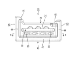
コネクタ10は、図1および図2に示すように、合成樹脂製のコネクタハウジング20と、ジョイント端子30と、リテーナ40とを備えて構成されている。コネクタハウジング20の内部には、複数のキャビティ21が前後方向に貫通する形態で左右方向に並んで設けられている。このキャビティ21には、相手側端子50が後方から挿入されて収容可能とされている。
As shown in FIGS. 1 and 2, the
また、コネクタハウジング20の前面には、ジョイント端子30が前方から挿入される端子挿入口22が前方に開口して設けられている。コネクタハウジング20の内部には、端子挿入口22から挿入されたジョイント端子30を収容する端子収容部24が設けられている。この端子収容部24は、左右方向に並んだ全キャビティ21に亘って設けられかつ全てのキャビティ21に連通している。
Further, a
ジョイント端子30は、導電性の良い金属板材をプレス加工することによって製造されており、帯状基部31から互いに所定の間隔を空けて複数の端子部32が突出した形状をなしている。帯状基部31には、隣り合う端子部32の間に位置する送り孔が複数設けられている。これらの送り孔のうち、並び方向の両端に配された2つの送り孔が、コネクタハウジング20に設けられた係合突起(図示せず)と係合することでジョイント端子30が端子収容部24に保持されるようになっている。
The
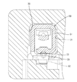
キャビティ21は、図9に示すように、方形の孔形状をなしている。このキャビティ21の内壁における対角をなす位置(図示左上と図示右下)には一対の隙詰めリブ23が設けられている。左上の隙詰めリブ23は、図7に示すように、前後方向に延びる形態をなしており、右下の隙詰めリブ23も、図8に示すように、前後方向に延びる形態をなしている。両隙詰めリブ23はいずれも、キャビティ21における相手側端子50の角筒部51の収容領域に形成されている。両隙詰めリブ23は、キャビティ21の内壁と角筒部51との間の隙間を詰めることで、相手側端子50の上下方向および左右方向におけるガタツキや左回り方向のローリングなどを規制している。
As shown in FIG. 9, the
角筒部51の底壁には、図9に示すように、下方に叩き出すことによって係止段部52が設けられている。この係止段部52は、キャビティ21の底壁に設けられたランス25と前後方向に係止するようになっている。図9は、相手側端子50が正規の姿勢でキャビティ21に収容された状態を示しており、係止段部52のうちランス25と係止する領域を破線で示している。一方、図10は、相手側端子50が左回りに最も傾き角度が大きい姿勢でキャビティ21に収容された状態を示しており、同様に係止段部52のうちランス25と係止する領域を破線で示している。図10においては、角筒部51が両隙詰めリブ23,23に当接することで、相手側端子50の傾き角度が最小限に抑えられている。この比較として図11は、隙詰めリブを設けていない場合に相手側端子50が左回りに最も傾き角度が大きい姿勢でキャビティ21に収容された状態を示している。図10と図11を比較すればわかるように、両隙詰めリブ23,23を設けたことにより、係止段部52とランス25との係り代(破線領域)が大幅に増加しており、この結果、相手側端子50が傾いた状態におけるランス25による係止力を向上できることになる。
As shown in FIG. 9, a
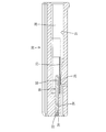
ランス25は、図8に示すように、片持ち状をなして前方に突出する形態をなしている。キャビティ21の底壁におけるランス25の左右両側と前側には、図4に示すように、ランス25の撓み動作を可能にさせる周溝が形成されており、この周溝によってランス25がその基端部(後端部)を支点として先端部(前端部)が上下方向に弾性撓み可能とされている。
As shown in FIG. 8, the
ランス25の周溝のうち、前側を除く左右両側の部分は、スリット26とされている。すなわち、ランス25の左右両側に両スリット26が形成されている。スリット26のうち左右両端を除く内側スリット26は、隣り合うキャビティ21を隔離する隔壁27を上下方向に切り欠くことで形成されている。また、スリット26のうち左右両端に位置する外側スリット26は、コネクタハウジング20の左右方向における側壁28の内側面を左右方向外側に切り欠くとともに上下方向に切り欠くことで形成されている。
Of the circumferential groove of the
さて、本実施形態におけるリテーナ40は、常には、コネクタハウジング20に組み付けられて使用されるのではなく、相手側端子50に連なる電線(図示せず)が強く引っ張られるなどしてランス25による係止力だけでは足りない場合、つまり、さらなる係止力が必要とされる場合に限って、コネクタハウジング20に組み付けられて使用されるようになっている。したがって、コネクタハウジング20には、リテーナ40を組み付けるためのリテーナ装着部などが設けられていない。
Now, the
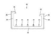
リテーナ40は、図2、図12、および図13に示すように、複数の位置決めリブ41が左右方向に並んで設けられたベース部42と、このベース部42の左右方向両側縁から立ち上がる一対のロック部43とから構成されている。さらに、ロック部43は、コネクタハウジング20の左右方向両側面に沿って配される側壁44と、この側壁44の上端から内側に突出してコネクタハウジング20の天井面に沿って配される係止爪45とから構成されている。コネクタハウジング20の天井面は、図6に示すように、その一側縁部が上方に突出して形成されており、これに伴って両ロック部43の一方が他方よりも高く形成されている。
As shown in FIGS. 2, 12, and 13, the
リテーナ40をコネクタハウジング20に対して下方から組み付けると、図1に示すように、ロック部43の係止爪45がコネクタハウジング20の天井面に引っ掛かって上下方向に係止することにより、リテーナ40の下方への脱落が規制される。
When the
また、位置決めリブ41は、図4および図5に示すように、スリット26に挿入され、位置決めリブ41の前後両端部が、スリット26の孔縁における前後両端部に対して前後方向に係止するようになっている。これにより、リテーナ40が前後方向に位置決めされる。
As shown in FIGS. 4 and 5, the
これと同時に、図4に示すように、位置決めリブ41の左右両側縁部が、スリット26の孔縁における左右両側縁部に対して左右方向に係止するようになっている。これにより、リテーナ40が左右方向に位置決めされる。さらに、コネクタハウジング20の両側壁28はそれぞれ、左右両端に位置する外側スリット26とロック部43の側壁44との間に適合して収容される。これにより、リテーナ40が左右方向に確実に位置決めされるようになっている。
At the same time, as shown in FIG. 4, the left and right side edges of the
このようにしてリテーナ40は、前後方向、左右方向、および上下方向に位置決めされ、ベース部42がランス25の撓み空間内に配置される。このため、電線が無理に引っ張られるなどしてランス25が撓むことを規制し、ランス25による係止力を向上させることができる。
In this way, the
以上のように本実施形態によると、リテーナ40を必要に応じて後からコネクタハウジング20に組み付けることができる。すなわち、コネクタ10の使用状況に応じて、リテーナ40を選択的に取付可能に構成したから、リテーナ40の有無によって専用のコネクタハウジングをそれぞれ設ける必要がない。そして、係止力を向上させる必要がある場合に、リテーナ40を位置決め状態でコネクタハウジング20に脱落不能に取り付けることにより、ランス25がリテーナ40のベース部42によって撓み変形することが規制され、ランス25による係止力を向上させることができる。
As described above, according to the present embodiment, the
また、ランス25の周囲に形成された周溝に位置決めリブ41が嵌り込んで、リテーナ40の前後方向および左右方向の位置決めを行うようにしたから、周溝とは別に、位置決めリブが嵌り込むスリットを設ける必要がなく、コネクタハウジング20の構成を簡素化することができる。
In addition, since the
また、両ロック部43の両側壁44によってコネクタハウジング20を左右方向両側から抱え込むとともに、左右両端の両位置決めリブ41と両ロック部43の両側壁44との間にコネクタハウジング20の両側壁28をそれぞれ収容しているから、リテーナ40の左右方向の位置決めを確実に行うことができる。
Further, the
また、スリット26の前後両端部に係止する一対の位置決め凸部を個別に設けるのではなく、位置決めリブ41として一体に設けたため、位置決め凸部の強度を高めることができる。
In addition, since the pair of positioning projections that are engaged with the front and rear end portions of the
さらに、キャビティ21の内壁における対角をなす位置に、一対の隙詰めリブ23,23を設けたから、両隙詰めリブ23,23に角筒部51を接触させて相手側端子50のローリングを抑え、ランス25と係止段部52との係止代を確保することで、ランス25による係止力を向上させることができる。
Furthermore, since the pair of
<他の実施形態>
本発明は上記記述及び図面によって説明した実施形態に限定されるものではなく、例えば次のような実施形態も本発明の技術的範囲に含まれる。
(1)上記実施形態では前後一対の位置決め凸部を位置決めリブ41として一体に設けているものの、本発明によると、位置決め凸部を個別に設けてもよく、この場合、スリットの代わりに、位置決め凸部が嵌り込む位置決め孔を設けてもよい。
<Other embodiments>
The present invention is not limited to the embodiments described with reference to the above description and drawings. For example, the following embodiments are also included in the technical scope of the present invention.
(1) Although the pair of front and rear positioning protrusions are integrally provided as the
(2)上記実施形態ではキャビティ21の内壁に一対の隙詰めリブ23を設けているものの、本発明によると、いずれか一方の隙詰めリブのみを設けてもよい。
(2) Although the pair of
20…コネクタハウジング
21…キャビティ
23…隙詰めリブ
25…ランス
26…スリット
28…側壁
30…ジョイント端子
40…リテーナ
41…位置決めリブ
43…ロック部
50…相手側端子
DESCRIPTION OF
Claims (6)
前記リテーナは、前記コネクタハウジングの左右方向両側に配設されて前記コネクタハウジングの外面における他側の面に係止することで前記一側への脱落を規制する一対のロック部と、前記コネクタハウジングの外面における前記一側の面に形成された係止凹部と係止することで前後方向および左右方向の位置決めを行う複数の位置決め凸部とを備えていることを特徴とするリテーナの取付構造。 A connector housing having a plurality of cavities arranged in the left-right direction in a form that penetrates in the front-rear direction, and a lance that is provided for each of the cavities to prevent the mating terminal housed in the cavity from being removed, and the connector housing And a joint terminal for short-circuiting the mating terminals housed in the cavity, the lance is formed by connecting one surface of the outer surface of the connector housing and the inner wall of the cavity. A retainer mounting structure provided in between and capable of being bent to the one side, wherein a retainer for restricting the displacement of the lance to the one side is attachable to the connector housing;
The retainer is disposed on both left and right sides of the connector housing and is engaged with the other surface of the outer surface of the connector housing to restrict the dropout to the one side, and the connector housing A retainer mounting structure, comprising: a plurality of positioning protrusions that perform positioning in the front-rear direction and the left-right direction by engaging with a locking recess formed on the one side surface of the outer surface of the retainer.
Priority Applications (1)
| Application Number | Priority Date | Filing Date | Title |
|---|---|---|---|
| JP2011004160A JP5618149B2 (en) | 2011-01-12 | 2011-01-12 | Retainer mounting structure |
Applications Claiming Priority (1)
| Application Number | Priority Date | Filing Date | Title |
|---|---|---|---|
| JP2011004160A JP5618149B2 (en) | 2011-01-12 | 2011-01-12 | Retainer mounting structure |
Publications (2)
| Publication Number | Publication Date |
|---|---|
| JP2012146523A true JP2012146523A (en) | 2012-08-02 |
| JP5618149B2 JP5618149B2 (en) | 2014-11-05 |
Family
ID=46789911
Family Applications (1)
| Application Number | Title | Priority Date | Filing Date |
|---|---|---|---|
| JP2011004160A Expired - Fee Related JP5618149B2 (en) | 2011-01-12 | 2011-01-12 | Retainer mounting structure |
Country Status (1)
| Country | Link |
|---|---|
| JP (1) | JP5618149B2 (en) |
Cited By (1)
| Publication number | Priority date | Publication date | Assignee | Title |
|---|---|---|---|---|
| US9761978B2 (en) | 2015-10-06 | 2017-09-12 | Hyundai Motor Company | Multi-ground connector for vehicle |
Citations (4)
| Publication number | Priority date | Publication date | Assignee | Title |
|---|---|---|---|---|
| JPH03130163U (en) * | 1990-04-10 | 1991-12-26 | ||
| JPH0917507A (en) * | 1995-06-26 | 1997-01-17 | Yazaki Corp | Connector |
| JPH11185857A (en) * | 1997-12-22 | 1999-07-09 | Sumitomo Wiring Syst Ltd | Disassembling method of connector and connector |
| JP2010067406A (en) * | 2008-09-09 | 2010-03-25 | Autonetworks Technologies Ltd | Wire harness including short circuit, and method of manufacturing the same |
-
2011
- 2011-01-12 JP JP2011004160A patent/JP5618149B2/en not_active Expired - Fee Related
Patent Citations (4)
| Publication number | Priority date | Publication date | Assignee | Title |
|---|---|---|---|---|
| JPH03130163U (en) * | 1990-04-10 | 1991-12-26 | ||
| JPH0917507A (en) * | 1995-06-26 | 1997-01-17 | Yazaki Corp | Connector |
| JPH11185857A (en) * | 1997-12-22 | 1999-07-09 | Sumitomo Wiring Syst Ltd | Disassembling method of connector and connector |
| JP2010067406A (en) * | 2008-09-09 | 2010-03-25 | Autonetworks Technologies Ltd | Wire harness including short circuit, and method of manufacturing the same |
Cited By (1)
| Publication number | Priority date | Publication date | Assignee | Title |
|---|---|---|---|---|
| US9761978B2 (en) | 2015-10-06 | 2017-09-12 | Hyundai Motor Company | Multi-ground connector for vehicle |
Also Published As
| Publication number | Publication date |
|---|---|
| JP5618149B2 (en) | 2014-11-05 |
Similar Documents
| Publication | Publication Date | Title |
|---|---|---|
| JP5598384B2 (en) | connector | |
| WO2018163788A1 (en) | Shielded terminal and shielded connector | |
| JP5827082B2 (en) | Electrical connector | |
| JP6393301B2 (en) | connector | |
| JP2019185911A (en) | connector | |
| JP5476999B2 (en) | connector | |
| WO2016084587A1 (en) | Connector | |
| JP2018152216A (en) | Terminal unit and connector | |
| US9306330B2 (en) | Lever-type connector and connector assembly | |
| JP2012094289A (en) | Electric wire cover and connector | |
| JP6057468B2 (en) | Waterproof connector | |
| JP5561127B2 (en) | connector | |
| JP5618149B2 (en) | Retainer mounting structure | |
| JP2012054206A (en) | Connector | |
| JP4168911B2 (en) | connector | |
| JP5183315B2 (en) | connector | |
| JP5565184B2 (en) | connector | |
| WO2023223807A1 (en) | Connector | |
| JP7132273B2 (en) | connector | |
| JP2009272239A (en) | Connector | |
| JP2018156764A (en) | connector | |
| US10418744B2 (en) | Connector | |
| JP6491008B2 (en) | Connector connection structure | |
| JP6164433B2 (en) | connector | |
| JP5810834B2 (en) | connector |
Legal Events
| Date | Code | Title | Description |
|---|---|---|---|
| A621 | Written request for application examination |
Free format text: JAPANESE INTERMEDIATE CODE: A621 Effective date: 20130607 |
|
| A977 | Report on retrieval |
Free format text: JAPANESE INTERMEDIATE CODE: A971007 Effective date: 20140210 |
|
| A131 | Notification of reasons for refusal |
Free format text: JAPANESE INTERMEDIATE CODE: A131 Effective date: 20140401 |
|
| A521 | Written amendment |
Free format text: JAPANESE INTERMEDIATE CODE: A523 Effective date: 20140521 |
|
| TRDD | Decision of grant or rejection written | ||
| A01 | Written decision to grant a patent or to grant a registration (utility model) |
Free format text: JAPANESE INTERMEDIATE CODE: A01 Effective date: 20140821 |
|
| A61 | First payment of annual fees (during grant procedure) |
Free format text: JAPANESE INTERMEDIATE CODE: A61 Effective date: 20140903 |
|
| R150 | Certificate of patent or registration of utility model |
Ref document number: 5618149 Country of ref document: JP Free format text: JAPANESE INTERMEDIATE CODE: R150 |
|
| LAPS | Cancellation because of no payment of annual fees |