JP2012146109A - Control apparatus for machine tool - Google Patents
Control apparatus for machine tool Download PDFInfo
- Publication number
- JP2012146109A JP2012146109A JP2011003631A JP2011003631A JP2012146109A JP 2012146109 A JP2012146109 A JP 2012146109A JP 2011003631 A JP2011003631 A JP 2011003631A JP 2011003631 A JP2011003631 A JP 2011003631A JP 2012146109 A JP2012146109 A JP 2012146109A
- Authority
- JP
- Japan
- Prior art keywords
- program
- block
- storage unit
- unit
- execution
- Prior art date
- Legal status (The legal status is an assumption and is not a legal conclusion. Google has not performed a legal analysis and makes no representation as to the accuracy of the status listed.)
- Granted
Links
Images


Classifications
-
- G—PHYSICS
- G05—CONTROLLING; REGULATING
- G05B—CONTROL OR REGULATING SYSTEMS IN GENERAL; FUNCTIONAL ELEMENTS OF SUCH SYSTEMS; MONITORING OR TESTING ARRANGEMENTS FOR SUCH SYSTEMS OR ELEMENTS
- G05B19/00—Programme-control systems
- G05B19/02—Programme-control systems electric
- G05B19/18—Numerical control [NC], i.e. automatically operating machines, in particular machine tools, e.g. in a manufacturing environment, so as to execute positioning, movement or co-ordinated operations by means of programme data in numerical form
- G05B19/406—Numerical control [NC], i.e. automatically operating machines, in particular machine tools, e.g. in a manufacturing environment, so as to execute positioning, movement or co-ordinated operations by means of programme data in numerical form characterised by monitoring or safety
- G05B19/4068—Verifying part programme on screen, by drawing or other means
-
- G—PHYSICS
- G05—CONTROLLING; REGULATING
- G05B—CONTROL OR REGULATING SYSTEMS IN GENERAL; FUNCTIONAL ELEMENTS OF SUCH SYSTEMS; MONITORING OR TESTING ARRANGEMENTS FOR SUCH SYSTEMS OR ELEMENTS
- G05B19/00—Programme-control systems
- G05B19/02—Programme-control systems electric
- G05B19/18—Numerical control [NC], i.e. automatically operating machines, in particular machine tools, e.g. in a manufacturing environment, so as to execute positioning, movement or co-ordinated operations by means of programme data in numerical form
- G05B19/408—Numerical control [NC], i.e. automatically operating machines, in particular machine tools, e.g. in a manufacturing environment, so as to execute positioning, movement or co-ordinated operations by means of programme data in numerical form characterised by data handling or data format, e.g. reading, buffering or conversion of data
-
- G—PHYSICS
- G05—CONTROLLING; REGULATING
- G05B—CONTROL OR REGULATING SYSTEMS IN GENERAL; FUNCTIONAL ELEMENTS OF SUCH SYSTEMS; MONITORING OR TESTING ARRANGEMENTS FOR SUCH SYSTEMS OR ELEMENTS
- G05B19/00—Programme-control systems
- G05B19/02—Programme-control systems electric
- G05B19/18—Numerical control [NC], i.e. automatically operating machines, in particular machine tools, e.g. in a manufacturing environment, so as to execute positioning, movement or co-ordinated operations by means of programme data in numerical form
- G05B19/4155—Numerical control [NC], i.e. automatically operating machines, in particular machine tools, e.g. in a manufacturing environment, so as to execute positioning, movement or co-ordinated operations by means of programme data in numerical form characterised by programme execution, i.e. part programme or machine function execution, e.g. selection of a programme
-
- G—PHYSICS
- G05—CONTROLLING; REGULATING
- G05B—CONTROL OR REGULATING SYSTEMS IN GENERAL; FUNCTIONAL ELEMENTS OF SUCH SYSTEMS; MONITORING OR TESTING ARRANGEMENTS FOR SUCH SYSTEMS OR ELEMENTS
- G05B2219/00—Program-control systems
- G05B2219/30—Nc systems
- G05B2219/36—Nc in input of data, input key till input tape
- G05B2219/36073—Display original and modified part in different colour, highlight, shading, filling
Abstract
Description
本発明は、工具及びワークを相対移動させる送り機構を制御する工作機械の制御装置に関し、更に詳しくは、NCプログラムやパラメータを編集可能に構成された工作機械の制御装置に関する。 The present invention relates to a machine tool control apparatus that controls a feed mechanism that relatively moves a tool and a workpiece, and more particularly to a machine tool control apparatus configured to be able to edit NC programs and parameters.
工作機械の制御装置として、従来、例えば、特開平7−227739号公報に開示されたものが知られている。この制御装置は、NCプログラムを記憶するプログラム記憶部と、プログラム記憶部に格納されたNCプログラムの実行時に、NCプログラムで指令された送り速度や主軸回転速度を変更するためのオーバーライドスイッチと、オーバーライドスイッチのオーバーライド値を記憶するオーバーライド値記憶部と、オーバーライド値記憶部に格納されたオーバーライド値を基に、プログラム記憶部に格納されたNCプログラムを編集して、このNCプログラムで指令された送り速度や主軸回転速度を、オーバーライド値に応じた送り速度や主軸回転速度に変更する編集部とを備える。 As a control device for a machine tool, for example, one disclosed in Japanese Patent Laid-Open No. 7-227739 has been known. The control device includes a program storage unit for storing an NC program, an override switch for changing a feed speed and a spindle rotation speed commanded by the NC program when the NC program stored in the program storage unit is executed, and an override switch Based on the override value storage unit for storing the switch override value and the override value stored in the override value storage unit, the NC program stored in the program storage unit is edited, and the feed speed commanded by this NC program And an editing unit that changes the spindle rotation speed to a feed speed or a spindle rotation speed according to the override value.
そして、この制御装置では、NCプログラムの実行時にオーバーライドスイッチが操作されると、そのときのオーバーライド値がオーバーライド値記憶部に格納され、NCプログラムの指令値(送り速度や主軸回転速度)がオーバーライド値に応じた指令値に変更される。 In this control device, when the override switch is operated during execution of the NC program, the override value at that time is stored in the override value storage unit, and the NC program command values (feed speed and spindle rotation speed) are used as override values. The command value is changed according to
また、この他、オペレータがデータを直接入力して、送り速度,主軸回転速度及び移動位置といった指令値やコードを変更したり、工具オフセット量及びワーク原点オフセット量といったパラメータを変更する編集機能を備えた制御装置もある。 In addition, it has an editing function that allows operators to directly input data to change command values and codes such as feed speed, spindle rotation speed, and moving position, and parameters such as tool offset and workpiece zero offset. There is also a control device.
しかしながら、上記従来の制御装置では、例えば、指令値やパラメータ、コードを変更したときに、変更ミスによって、間違った値や不適切な値に変更されたり、間違ったコードに変更される恐れがあり、そして、変更ミスのあるNCプログラムが実行されると、工具がワークや工作機械構造体と干渉するという問題を生じたり、ワークの加工精度が低下するという問題を生じる。 However, in the above-described conventional control device, for example, when a command value, a parameter, or a code is changed, there is a possibility that it is changed to an incorrect value or an inappropriate value due to a change error, or changed to an incorrect code. When an NC program with a change error is executed, there arises a problem that the tool interferes with the workpiece or the machine tool structure, or a problem that the machining accuracy of the workpiece is lowered.
本発明は、以上の実情に鑑みなされたものであって、指令値やパラメータ、コードを変更したNCプログラムを実行する場合に、安全に且つ加工精度を低下させることなく、ワークを加工することができる工作機械の制御装置の提供をその目的とする。 The present invention has been made in view of the above circumstances, and when executing an NC program in which command values, parameters, and codes are changed, a workpiece can be machined safely and without reducing machining accuracy. An object is to provide a machine tool control device.
上記目的を達成するための本発明は、
工具及びワークを相対移動させる送り機構を制御する工作機械の制御装置であって、
NCプログラムを記憶するプログラム記憶部と、
NCプログラムを構成するコードに関するパラメータを記憶するパラメータ記憶部と、
前記プログラム記憶部に格納されたNCプログラムをブロック毎に順次解析して、前記送り機構に関する動作指令を抽出するプログラム解析部と、
前記プログラム解析部によって順次抽出される動作指令と、前記パラメータ記憶部に格納されたパラメータとを基に、該動作指令を実行して前記送り機構を制御する実行制御部と、
前記プログラム記憶部に格納されたNCプログラム、及び前記パラメータ記憶部に格納されたパラメータの内の少なくとも一方を変更するデータ変更部とを備えた工作機械の制御装置において、
前記データ変更部によって変更された変更箇所に関する変更箇所情報が格納される変更箇所情報記憶部を備え、
前記実行制御部は、前記プログラム解析部によって抽出された動作指令を実行するに当たり、該動作指令に係るブロックが変更箇所に係るブロックの1つ前のブロックであるか否かを、前記変更箇所情報記憶部に格納された変更箇所情報を基に確認して、1つ前のブロックであると判断した場合には、該動作指令の実行前又は実行後に前記送り機構の作動を一時停止させるように構成されていることを特徴とする工作機械の制御装置に係る。
To achieve the above object, the present invention provides:
A machine tool control device for controlling a feed mechanism for relatively moving a tool and a workpiece,
A program storage unit for storing NC programs;
A parameter storage unit for storing parameters relating to codes constituting the NC program;
A program analysis unit that sequentially analyzes the NC program stored in the program storage unit for each block and extracts an operation command related to the feed mechanism;
Based on the operation command sequentially extracted by the program analysis unit and the parameter stored in the parameter storage unit, an execution control unit that executes the operation command and controls the feed mechanism;
In a machine tool control device comprising: an NC program stored in the program storage unit; and a data change unit that changes at least one of parameters stored in the parameter storage unit.
A change location information storage unit that stores change location information related to the change location changed by the data change unit,
The execution control unit, when executing the operation command extracted by the program analysis unit, whether the block related to the operation command is a block immediately before the block related to the change location, the change location information When checking based on the changed part information stored in the storage unit and determining that it is the previous block, the operation of the feed mechanism is temporarily stopped before or after the execution of the operation command. The present invention relates to a control device for a machine tool.
この発明によれば、プログラム記憶部に格納されたNCプログラムや、パラメータ記憶部に格納されたパラメータが、データ変更部によって変更されると、その変更箇所に関する変更箇所情報が変更箇所情報記憶部に格納される。尚、前記パラメータとしては、例えば、工具長補正,工具径補正,工具位置補正及び工具摩耗補正に用いられるオフセット量(工具オフセット量)やワーク原点オフセット量などが挙げられる。 According to the present invention, when the NC program stored in the program storage unit or the parameter stored in the parameter storage unit is changed by the data changing unit, the changed part information related to the changed part is stored in the changed part information storage unit. Stored. Examples of the parameters include an offset amount (tool offset amount) used for tool length correction, tool radius correction, tool position correction, and tool wear correction, and a workpiece origin offset amount.
この後、プログラム記憶部に格納されたNCプログラムが実行されると、プログラム解析部により、このNCプログラムがブロック毎に順次解析されて、送り機構に関する動作指令が抽出され、抽出された動作指令と、パラメータ記憶部に格納されたパラメータとを基に、実行制御部により、当該動作指令が順次実行されて送り機構が制御される。 Thereafter, when the NC program stored in the program storage unit is executed, the program analysis unit sequentially analyzes the NC program for each block, extracts operation commands related to the feed mechanism, and extracts the extracted operation commands and Based on the parameters stored in the parameter storage unit, the operation control unit sequentially executes the operation commands to control the feed mechanism.
このとき、実行制御部においては、抽出された動作指令が実行される際に、当該動作指令に係るブロックが変更箇所に係るブロックの1つ前のブロックであるか否かが、変更箇所情報記憶部に格納された変更箇所情報を基に確認され、1つ前のブロックである場合には、当該動作指令の実行前又は実行後に送り機構の作動が一時停止せしめられる。 At this time, in the execution control unit, when the extracted operation command is executed, whether or not the block related to the operation command is the block immediately before the block related to the change location is stored in the change location information storage. In the case of the previous block, which is confirmed based on the changed part information stored in the section, the operation of the feed mechanism is temporarily stopped before or after execution of the operation command.
尚、一時停止後、再度、送り機構を動作させる態様としては、オペレータによって入力される加工再開信号を実行制御部が受信してから加工を再開する態様を、一例として挙げることができる。 An example of a mode in which the feed mechanism is operated again after the temporary stop is a mode in which machining is resumed after the execution control unit receives a machining resumption signal input by the operator.
斯くして、本発明に係る工作機械の制御装置によれば、NCプログラムやパラメータが変更された場合には、その変更箇所に係るブロックより1つ前のブロックに係る動作指令の実行前又は実行後に送り機構の作動が一時停止するので、変更箇所の確認をオペレータに促すことができる。これにより、指令値やパラメータ、コードを変更した際に、変更ミスによって、間違った値や不適切な値に変更したり、間違ったコードに変更していたとしても、そのことをオペレータに気付かせることができる。したがって、工具がワークや工作機械構造体と干渉したり、ワークの加工精度が低下するといった問題が生じるのを防止することができる。 Thus, according to the machine tool control device of the present invention, when the NC program or parameter is changed, before or after the execution of the operation command related to the block immediately before the block related to the changed portion. Since the operation of the feeding mechanism is temporarily stopped later, it is possible to prompt the operator to confirm the changed portion. As a result, when the command value, parameter, or code is changed, even if it is changed to an incorrect value or an inappropriate value due to a change mistake or changed to an incorrect code, the operator is made aware of it. be able to. Therefore, it is possible to prevent the problem that the tool interferes with the workpiece or the machine tool structure or the machining accuracy of the workpiece is lowered.
尚、前記制御装置は、前記送り機構の作動を一時停止させるブロックを示した停止ブロックを記憶する停止ブロック記憶部と、前記プログラム記憶部に格納されたNCプログラムと、前記変更箇所情報記憶部に格納された変更箇所情報とを基に、変更箇所に係るブロックの1つ前のブロックを解析して、切削指令に関するブロックであるか否かを確認し、切削指令に関するブロックではないと判断した場合には、該1つ前のブロックを停止ブロックとして前記停止ブロック記憶部に格納する一方、切削指令に関するブロックであると判断した場合には、前記1つ前のブロックよりも更に前のブロックを解析して、切削指令に関するブロックではないブロックであり且つ変更箇所に係るブロックに最も近いブロックを認識し、認識したブロックを停止ブロックとして前記停止ブロック記憶部に格納するブロック解析部とを備え、前記実行制御部は、前記プログラム解析部によって抽出された動作指令を実行するに当たり、該動作指令に係るブロックが停止ブロックであるか否かを、前記停止ブロック記憶部に格納された停止ブロックを基に確認して、停止ブロックであると判断した場合には、該動作指令の実行前又は実行後に前記送り機構の作動を一時停止させるように構成されていても良い。 The control device includes a stop block storage unit that stores a stop block indicating a block for temporarily stopping the operation of the feed mechanism, an NC program stored in the program storage unit, and a change location information storage unit. When the block immediately before the block related to the changed part is analyzed based on the stored changed part information to check whether the block is related to the cutting command, and when it is determined that the block is not related to the cutting command The previous block is stored in the stop block storage unit as a stop block, and if it is determined that the block is related to a cutting command, the block before the previous block is analyzed. Then, the block which is not a block related to the cutting command and which is closest to the block related to the changed part is recognized and recognized. A block analysis unit that stores the stop block in the stop block storage unit, and when the execution control unit executes the operation command extracted by the program analysis unit, the block related to the operation command is a stop block Whether or not it is determined to be a stop block, the operation of the feed mechanism is temporarily suspended before or after execution of the operation command. It may be configured to stop.
この場合、変更箇所情報が変更箇所情報記憶部に格納されると、この変更箇所情報と、プログラム記憶部に格納されたNCプログラムとを基に、ブロック解析部により、変更箇所に係るブロックの1つ前のブロックが解析されて、切削指令に関するブロックであるか否かが確認され、切削指令に関するブロックではないときには、当該1つ前のブロックが停止ブロックとして停止ブロック記憶部に格納される一方、切削指令に関するブロックであるときには、1つ前のブロックよりも更に前のブロックが解析されて、切削指令に関するブロックではないブロックであり且つ変更箇所に係るブロックに最も近いブロックが認識され、認識されたブロックが停止ブロックとして停止ブロック記憶部に格納される。
In this case, when the changed part information is stored in the changed part information storage unit, the
そして、実行制御部では、抽出された動作指令が実行される際、当該動作指令に係るブロックが停止ブロックであるか否かが、停止ブロック記憶部に格納された停止ブロックを基に確認され、停止ブロックである場合には、当該動作指令の実行前又は実行後に送り機構の作動が一時停止せしめられる。 Then, in the execution control unit, when the extracted operation command is executed, whether the block related to the operation command is a stop block is confirmed based on the stop block stored in the stop block storage unit, If it is a stop block, the operation of the feed mechanism is temporarily stopped before or after the operation command is executed.
このように、切削指令に関するブロック以外のブロックが停止ブロックとして設定されるので、切削途中で工具及びワークの相対移動が一時停止するのを防止することができ、切削途中における工具及びワークの移動停止によりワークの加工精度が低下するのを防止することができる。 In this way, since blocks other than the block relating to the cutting command are set as stop blocks, it is possible to prevent the relative movement of the tool and the work from being temporarily stopped during the cutting, and the movement of the tool and the work during the cutting is stopped. Therefore, it is possible to prevent the machining accuracy of the workpiece from being lowered.
また、前記制御装置は、前記プログラム記憶部に格納されたNCプログラムに関する履歴情報であって、前記NCプログラム及びパラメータの少なくとも一方の変更後における実行実績の有無についての情報を含んだ履歴情報を記憶する履歴情報記憶部と、前記実行制御部及びデータ変更部における処理を監視し、変更後における実行実績の無いNCプログラムが前記実行制御部によって実行された場合には、前記履歴情報記憶部に格納された該NCプログラムの実行実績を有りに更新するとともに、前記NCプログラム及びパラメータの内の少なくとも一方が前記データ変更部によって変更された場合には、前記履歴情報記憶部に格納された、対応するNCプログラムの実行実績を無しに更新する履歴情報管理部とを備え、前記実行制御部は、前記プログラム解析部によって抽出された動作指令を実行するに当たり、該実行するNCプログラムが変更後における実行実績の無いNCプログラムであるか否かを、前記履歴情報記憶部に格納された履歴情報を基に確認して、変更後における実行実績の無いNCプログラムであると判断した場合に、前記所定のブロックに係る動作指令の実行前又は実行後に前記送り機構の作動を一時停止させるように構成されていても良い。 Further, the control device stores history information related to the NC program stored in the program storage unit, the history information including information on the presence / absence of execution results after changing at least one of the NC program and parameters. The history information storage unit, and the processing in the execution control unit and the data change unit are monitored, and when an NC program having no execution performance after the change is executed by the execution control unit, the history information storage unit stores the history information storage unit When the NC program and the parameter are changed by the data changing unit, the corresponding execution result stored in the history information storage unit is updated. A history information management unit that updates the execution results of the NC program without any record, and the execution control unit In executing the operation command extracted by the program analysis unit, whether or not the NC program to be executed is an NC program with no execution performance after the change is stored in the history information stored in the history information storage unit. The operation of the feed mechanism is temporarily stopped before or after the execution of the operation command related to the predetermined block when it is determined that the NC program has not been executed after the change. May be.
この場合、変更後における実行実績の無いNCプログラムが実行制御部によって実行されると、履歴情報管理部により、履歴情報記憶部に格納された当該NCプログラムの実行実績が有りに更新され、NCプログラム及びパラメータの内の少なくとも一方がデータ変更部によって変更されると、履歴情報管理部により、履歴情報記憶部に格納された、対応するNCプログラムの実行実績が無しに更新される。 In this case, when the execution control unit executes an NC program with no execution results after the change, the history information management unit updates the execution result of the NC program stored in the history information storage unit to be present. When at least one of the parameters is changed by the data changing unit, the history information management unit updates the corresponding NC program stored in the history information storage unit without any execution results.
また、実行制御部では、抽出された動作指令が実行される際、その実行NCプログラムが変更後における実行実績の無いNCプログラムであるか否かが、履歴情報記憶部に格納された履歴情報を基に確認され、変更後における実行実績の無いNCプログラムであるときに、前記所定のブロックに係る動作指令の実行前又は実行後に送り機構の作動が一時停止せしめられる。 Further, in the execution control unit, when the extracted operation command is executed, whether or not the execution NC program is an NC program having no execution result after the change is stored in the history information stored in the history information storage unit. When the NC program is confirmed on the basis and has no execution record after the change, the operation of the feed mechanism is temporarily stopped before or after the execution of the operation command related to the predetermined block.
このように、NCプログラムやパラメータの変更後、最初の実行時にのみ変更箇所に係るブロックの直前で加工を一時停止させ、2回目以降の実行時には一時停止させないようにすることができるので、毎回、変更箇所に係るブロックの直前で加工が一時停止し、ワークの加工が非効率となるのを防止することができる。 In this way, after the NC program or parameter is changed, machining can be paused just before the block related to the changed part only at the first execution, and not paused at the second and subsequent executions. It is possible to prevent the machining of the workpiece from becoming inefficient because the machining is temporarily stopped immediately before the block related to the changed portion.
また、前記制御装置は、画面表示手段と、前記実行制御部により実行中のNCプログラムを前記画面表示手段に表示する表示制御部とを備え、前記表示制御部は、前記実行制御部により実行中のNCプログラムを表示するに当たり、前記変更箇所情報記憶部に格納された変更箇所情報を基に、変更箇所の表示形式を、それ以外の箇所の表示形式と異ならせて表示するように構成されていても良い。 Further, the control device includes a screen display means and a display control section for displaying the NC program being executed by the execution control section on the screen display means, and the display control section is being executed by the execution control section. When displaying the NC program, the display of the changed part is configured to be displayed differently from the display format of the other parts based on the changed part information stored in the changed part information storage unit. May be.
この場合、実行制御部により実行中のNCプログラムが表示制御部によって画面表示手段に表示される際、変更箇所情報記憶部に格納された変更箇所情報を基に、変更箇所の表示形式が、それ以外の箇所の表示形式と異なるように表示されるので、オペレータは変更箇所を容易に認識することができる。尚、異なる表示形式としては、例えば、変更箇所に係るブロックを点滅させたり、表示色を異ならせたり、反転表示させることなどが挙げられる。 In this case, when the NC program being executed by the execution control unit is displayed on the screen display means by the display control unit, the display format of the changed part is based on the changed part information stored in the changed part information storage unit. Since it is displayed differently from the display format of other places, the operator can easily recognize the changed place. Note that examples of the different display formats include blinking a block relating to a changed portion, changing the display color, and displaying the image in reverse.
以上のように、本発明に係る工作機械の制御装置によれば、NCプログラムやパラメータが変更されたときには、その変更箇所に係るブロックの直前で送り機構の作動を一時停止させ、オペレータに注意させるようにしたので、安全に且つ加工精度を低下させることなく、ワークを加工することができる。 As described above, according to the machine tool control device of the present invention, when the NC program or parameter is changed, the operation of the feed mechanism is temporarily stopped immediately before the block related to the changed portion, and the operator is warned. Since it did in this way, a workpiece | work can be processed safely and without reducing a processing precision.
以下、本発明の具体的な実施形態について、添付図面に基づき説明する。 Hereinafter, specific embodiments of the present invention will be described with reference to the accompanying drawings.
図1に示すように、本例の制御装置1は、プログラム記憶部11,パラメータ記憶部12,プログラム編集部13,パラメータ編集部14,変更箇所情報記憶部15,プログラム解析部16,ブロック解析部17,停止ブロック記憶部18,履歴情報記憶部19,履歴情報管理部20,実行制御部21,表示制御部22,画面表示装置23及び入力装置(図示せず)などを備えており、X軸,Y軸及びZ軸の直交3軸方向に工具及びワークを相対移動させる送り機構6と、工具若しくはワークを保持し、保持した工具若しくはワークを主軸モータ7により軸中心に回転させる主軸装置などから構成される工作機械5に設けられている。
As shown in FIG. 1, the
前記プログラム記憶部11には、NCプログラムが格納され、前記パラメータ記憶部12には、NCプログラムを構成するコードに関するパラメータが格納される。尚、このパラメータの具体例としては、例えば、工具長補正,工具径補正,工具位置補正及び工具摩耗補正に用いられるオフセット量(工具オフセット量)やワーク原点オフセット量などが挙げられる。
The
前記プログラム編集部(データ変更部)13は、入力装置(図示せず)から入力されるデータを基に、プログラム記憶部11に格納されたNCプログラムを変更する。具体的には、送り速度,主軸回転速度及び移動位置といった指令値や、コードを変更する。図2に示した例では、15ブロック、17ブロック及び19ブロックのX軸方向における指令位置が−95から−96に変更されている。
The program editing unit (data changing unit) 13 changes the NC program stored in the
前記パラメータ編集部(データ変更部)14は、入力装置(図示せず)から入力されるデータを基に、パラメータ記憶部12に格納されたパラメータを変更する。図3に示した例では、13ブロックの工具長補正に関するパラメータについて、形状に関する項目の値が10.500から10.200に変更され、摩耗に関する項目の値が1.230から1.120に変更されている。
The parameter editing unit (data changing unit) 14 changes a parameter stored in the
前記変更箇所情報記憶部15には、プログラム編集部13によって変更されたNCプログラムの変更箇所や、パラメータ編集部14によって変更されたパラメータの変更箇所に関する変更箇所情報が格納される。この変更箇所情報には、例えば、変更箇所に係るブロックや、変更前及び変更後のデータなどに関する情報が含まれる。また、パラメータの場合、変更箇所に係るブロックとは、例えば、変更後のパラメータを参照するコード(指令)が含まれたブロックのことである。
The changed part
前記プログラム解析部16は、プログラム記憶部11に格納されたNCプログラムをブロック毎に順次解析して、送り機構6や主軸モータ7に関する動作指令を抽出する。送り機構6に関する動作指令としては、工具及びワークの送り速度、工具の移動位置、ワークの移動位置についての指令が挙げられ、主軸モータ7に関する動作指令としては、主軸の回転速度、主軸の回転開始、主軸の回転停止についての指令が挙げられる。
The
前記ブロック解析部17は、プログラム記憶部11に格納されたNCプログラムと、変更箇所情報記憶部15に格納された変更箇所情報とを基に、変更箇所に係るブロックよりも前のブロックを解析して、送り機構6及び主軸モータ7の作動を一時停止させるブロックたる停止ブロックを認識し、認識した停止ブロックを前記停止ブロック記憶部18に格納する。尚、停止ブロック記憶部18には、プログラム記憶部11に格納されたNCプログラムであって、プログラム編集部13やパラメータ編集部14による変更箇所を有するNCプログラムについて、前記停止ブロックが格納されている。
Based on the NC program stored in the
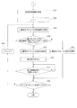
具体的には、ブロック解析部17は、図4に示すような一連の処理を実行するようになっており、まず、プログラム記憶部11に格納された変更後のNCプログラムを認識するとともに(ステップS1)、変更箇所情報記憶部15に格納された変更箇所情報を認識し(ステップS2)、変更箇所に係るブロックの1つ前のブロックを停止ブロックに設定する(ステップS3)。例えば、図2に示した例では、14ブロック、16ブロック及び18ブロックが停止ブロックに設定され、図3に示した例では、12ブロックが停止ブロックに設定される。
Specifically, the
この後、設定した停止ブロックを解析して、この停止ブロックが切削指令に関するブロックであるか否かを確認する(ステップS4)。切削指令に関するブロックであるか否かは、切削コードが有効になっているブロックであるか否かで判断することができる。 Thereafter, the set stop block is analyzed, and it is confirmed whether or not the stop block is a block related to a cutting command (step S4). Whether or not the block is related to the cutting command can be determined by whether or not the block is a block in which the cutting code is valid.
そして、切削指令に関するブロックであると判断した場合には、前記ステップS3で設定した停止ブロックの1つ前のブロックを停止ブロックとして再設定し(ステップS5)、再設定した停止ブロックを更に解析して、この停止ブロックが切削指令に関するブロックであるか否かを確認する(ステップS4)。このようにして、切削指令に関するブロックではない停止ブロックが見つかるまで前記ステップS4及びS5の処理を繰り返す。図2に示した例では、14ブロック及び18ブロックが切削指令に関するブロックであるため、切削指令に関するブロックではない停止ブロックとして13ブロック及び17ブロックが認識される。 If it is determined that the block is related to the cutting command, the block immediately before the stop block set in step S3 is reset as a stop block (step S5), and the reset stop block is further analyzed. Then, it is confirmed whether or not this stop block is a block related to a cutting command (step S4). In this way, the processes in steps S4 and S5 are repeated until a stop block that is not a block related to the cutting command is found. In the example illustrated in FIG. 2, the 14 blocks and the 18 blocks are blocks related to the cutting command, and therefore the 13 blocks and the 17 blocks are recognized as stop blocks that are not blocks related to the cutting command.
そして、切削指令に関するブロックではない停止ブロックを認識すると(ステップS4)、前記ステップS3で設定した停止ブロック、又は前記ステップS5で再設定した停止ブロックを前記停止ブロック記憶部18に格納して(ステップS6)、上記一連の処理を終了する。図2に示した例では、停止ブロックとして13ブロック、16ブロック及び17ブロックが停止ブロック記憶部18に格納され、図3に示した例では、停止ブロックとして12ブロックが停止ブロック記憶部18に格納される。
When a stop block that is not a block related to the cutting command is recognized (step S4), the stop block set in step S3 or the stop block reset in step S5 is stored in the stop block storage unit 18 (step S4). S6) The above series of processing ends. In the example shown in FIG. 2, 13 blocks, 16 blocks, and 17 blocks are stored in the stop
前記履歴情報記憶部19には、プログラム記憶部11に格納されたNCプログラムに関する履歴情報が格納される。この履歴情報は、図5に示すように、プログラム名、NCプログラム及びパラメータの少なくとも一方が変更されたか否か(変更箇所が有るか否か)、NCプログラム及びパラメータの少なくとも一方が変更された場合にはその変更後における実行実績の有無についての情報を含み、これらが相互に関連付けられている。尚、前記プログラム名は、図5のようにプログラム番号であっても、それ以外のファイル名であっても良い。
The history
前記履歴情報管理部20は、前記プログラム編集部13,パラメータ編集部14及び実行制御部21における処理を監視し、変更後における実行実績の無いNCプログラムの全ブロックが実行制御部21によって実行されると、履歴情報記憶部19に格納された当該NCプログラムの実行実績を有りに更新し、プログラム記憶部11に格納されたNCプログラムがプログラム編集部13によって変更されたり、パラメータ記憶部12に格納されたパラメータがパラメータ編集部14によって変更されると、履歴情報記憶部19に格納された、対応するNCプログラムの実行実績を無しに更新する。また、履歴情報管理部20は、プログラム記憶部11に新たなNCプログラムが格納されると、当該NCプログラムについての履歴情報を生成して履歴情報記憶部19に格納するようになっている。
The history
前記実行制御部21は、プログラム解析部16によって順次抽出される動作指令と、パラメータ記憶部12に格納されたパラメータと、停止ブロック記憶部18に格納された停止ブロックとを基に、当該動作指令を実行して送り機構6及び主軸モータ7を制御する。
The
具体的には、実行制御部21は、図6及び図7に示すような一連の処理を実行するようになっており、まず、履歴情報記憶部19に格納された履歴情報を認識して(ステップS11)、認識した履歴情報を基に、実行するNCプログラムに変更箇所が有るか否かを確認し(ステップS12)、変更箇所が有ると判断した場合(例えば、図5のプログラム名O0001,O0003及びO0004の場合)には、実行するNCプログラムが変更後における実行実績の有るNCプログラムであるか否かを更に確認する(ステップS13)。
Specifically, the
そして、実行実績が有ると判断した場合(例えば、図5のプログラム名O0001及びO0004の場合)、及び前記ステップS12で変更箇所が無いと判断した場合(例えば、図5のプログラム名O0002及びO0005の場合)には、カウンタnをn=1に設定し(ステップS14)、n番目のブロックの動作指令をプログラム解析部16から受信して(ステップS15)、受信した動作指令を実行する(ステップS16)。この後、NCプログラムの全ブロックについて動作指令を実行したか否かを確認し(ステップS17)、カウンタnを更新しつつNCプログラムの全ブロックについて動作指令を実行した後(ステップS17,S18)、上記一連の処理を終了する。 Then, when it is determined that there is a performance record (for example, in the case of the program names O0001 and O0004 in FIG. 5), and when it is determined in step S12 that there is no change location (for example, the program names O0002 and O0005 in FIG. 5). In the case, the counter n is set to n = 1 (step S14), the operation command for the nth block is received from the program analysis unit 16 (step S15), and the received operation command is executed (step S16). ). Thereafter, it is confirmed whether or not the operation command has been executed for all the blocks of the NC program (step S17), and the operation command is executed for all the blocks of the NC program while updating the counter n (steps S17 and S18). The above series of processing ends.
一方、前記ステップS13で実行実績が無いと判断した場合(例えば、図5のプログラム名O0003の場合)には、停止ブロック記憶部18に格納された停止ブロックを認識した後(ステップS19)、カウンタnをn=1に設定し(ステップS20)、n番目のブロックの動作指令をプログラム解析部16から受信して(ステップS21)、前記認識した停止ブロックを基に、n番目のブロックが停止ブロックであるか否かを確認する(ステップS22)。
On the other hand, if it is determined in step S13 that there is no execution result (for example, in the case of the program name O0003 in FIG. 5), after the stop block stored in the stop
そして、停止ブロックであると判断した場合には、前記受信した動作指令を実行した後(ステップS23)、停止指令を出力して送り機構6及び主軸モータ7の作動を一時停止させる(ステップS24)。例えば、図2に示した例では、13ブロック、16ブロック及び17ブロックの動作指令の実行後に送り機構6及び主軸モータ7の作動が一時停止せしめられ、図3に示した例では、12ブロックの動作指令の実行後に送り機構6及び主軸モータ7の作動が一時停止せしめられる。
If it is determined that the block is a stop block, the received operation command is executed (step S23), and then the stop command is output to temporarily stop the operation of the
この後、オペレータによって入力装置(図示せず)から加工再開信号が入力され、これを受信すると(ステップS25)、ステップS27の処理に進む。一方、前記ステップS22で停止ブロックではないと判断した場合には、前記受信した動作指令を実行して(ステップS26)、ステップS27の処理に進む。 Thereafter, when an operator inputs a machining resumption signal from an input device (not shown) and receives it (step S25), the process proceeds to step S27. On the other hand, if it is determined in step S22 that the block is not a stop block, the received operation command is executed (step S26), and the process proceeds to step S27.
そして、前記ステップS27では、NCプログラムの全ブロックについて動作指令を実行したか否かを確認し、カウンタnを更新しつつNCプログラムの全ブロックについて動作指令を実行した後(ステップS27,S28)、上記一連の処理を終了する。 In step S27, it is confirmed whether or not the operation command has been executed for all blocks of the NC program, and the operation command is executed for all blocks of the NC program while updating the counter n (steps S27 and S28). The above series of processing ends.
前記表示制御部22は、実行制御部21により実行中のNCプログラムを前記画面表示装置23に表示する。また、表示制御部22は、NCプログラムを表示するに当たり、変更箇所情報記憶部15に格納された変更箇所情報を基に、変更箇所の表示形式を、それ以外の箇所の表示形式と異ならせて表示する。
The
ここで、図2に示したNCプログラムの場合を一例に説明すると、例えば、図8に示すように、変更箇所に係るブロックである15ブロック、17ブロック及び19ブロックの表示を点滅させる。この他、15ブロック、17ブロック及び19ブロックの表示色を異ならせたり、15ブロック、17ブロック及び19ブロックを反転表示させるようにしても良い。 Here, the case of the NC program shown in FIG. 2 will be described as an example. For example, as shown in FIG. 8, the 15 blocks, 17 blocks, and 19 blocks, which are blocks related to the changed portion, are blinked. In addition, the display colors of 15 blocks, 17 blocks, and 19 blocks may be made different, or the 15 blocks, 17 blocks, and 19 blocks may be displayed in reverse.
以上のように構成された本例の制御装置1によれば、プログラム記憶部11に格納されたNCプログラムがプログラム編集部13により変更されたり、パラメータ記憶部12に格納されたパラメータがパラメータ編集部14により変更されると、その変更箇所に関する変更箇所情報が変更箇所情報記憶部15に格納されるとともに、履歴情報管理部20により、履歴情報記憶部19に格納された、対応するNCプログラムの実行実績が無しに更新される。
According to the
また、プログラム記憶部11に格納されたNCプログラムと、変更箇所情報記憶部15に格納された変更箇所情報とを基に、ブロック解析部17によって変更箇所に係るブロックよりも前のブロックが解析され、切削指令に関するブロックではないブロックであって変更箇所に係るブロックに最も近いブロックが停止ブロックとして停止ブロック記憶部18に格納される。
Further, based on the NC program stored in the
この後、プログラム記憶部11に格納されたNCプログラムがプログラム解析部16によりブロック毎に順次解析されて、送り機構6や主軸モータ7に関する動作指令が抽出され、抽出された動作指令と、パラメータ記憶部12に格納されたパラメータとを基に、実行制御部21によって当該動作指令が順次実行されて送り機構6や主軸モータ7が制御される。
Thereafter, the NC program stored in the
その際、実行制御部21では、まず、履歴情報記憶部19に格納された履歴情報を基に、その実行NCプログラムが変更後における実行実績の無いNCプログラムであるか否かが確認され、変更後における実行実績の無いNCプログラムであるときには、停止ブロック記憶部18に格納された停止ブロックに係る動作指令の実行後に、送り機構6及び主軸モータ7の作動が一時停止せしめられる一方、変更箇所が無いときや、変更箇所が有っても変更後における実行実績の有るNCプログラムであるときには、送り機構6及び主軸モータ7の作動が一時停止せしめられることなく、動作指令が順次実行される。
At that time, the
また、実行制御部21により実行中のNCプログラムは、表示制御部22によって画面表示装置23に表示されるが、変更箇所情報記憶部15に格納された変更箇所情報を基に認識される変更箇所については、その表示形式が、それ以外の箇所の表示形式と異なるように表示される。
Further, the NC program being executed by the
尚、実行制御部21によって変更後における実行実績の無いNCプログラムの全ブロックが実行されると、履歴情報管理部20により、履歴情報記憶部19に格納された当該NCプログラムの実行実績が有りに更新される。
When all the blocks of the NC program having no execution results after the change are executed by the
このように、本例の制御装置1によれば、NCプログラムやパラメータが変更された場合には、その変更箇所に係るブロックよりも1つ前のブロックに係る動作指令の実行後に送り機構6及び主軸モータ7の作動が一時停止するので、変更箇所の確認をオペレータに促すことができる。これにより、指令値やパラメータ、コードを変更した際に、変更ミスによって、間違った値や不適切な値に変更したり、間違ったコードに変更していたとしても、そのことをオペレータに気付かせることができる。したがって、工具がワークや工作機械構造体と干渉したり、ワークの加工精度が低下するといった問題が生じるのを防止することができる。
As described above, according to the
また、変更箇所に係るブロックより1つ前のブロックが切削指令に関するブロックであるときには、切削指令に関するブロックではないブロックであって変更箇所に係るブロックに最も近いブロックの実行後に送り機構6及び主軸モータ7の作動が一時停止するので、切削途中で工具及びワークの相対移動や主軸の回転が一時停止するのを防止することができ、切削途中における工具及びワークの移動停止や主軸の回転停止によりワークの加工精度が低下するのを防止することができる。
Further, when the block immediately before the block related to the changed portion is a block related to the cutting command, the
また、実行制御部21によって変更後における実行実績の無いNCプログラムの全ブロックが実行されると、履歴情報管理部20により、履歴情報記憶部19に格納された当該NCプログラムの実行実績が有りに更新されるので、NCプログラムやパラメータの変更後、最初の実行時にのみ変更箇所に係るブロックの直前で加工を一時停止させ、2回目以降の実行時には一時停止させないようにすることができ、毎回、変更箇所に係るブロックの直前で加工が一時停止し、ワークの加工が非効率となるのを防止することができる。この他、NCプログラムの全ブロックが実行された後に実行実績が更新されるので、NCプログラムの実行が途中で中断された場合にまで実行実績が更新され、すべての変更箇所が実行されないまま実行実績が更新されるのを防止することもできる。
When the
更に、実行制御部21により実行中のNCプログラムが表示制御部22によって画面表示装置23に表示される際、変更箇所情報記憶部15に格納された変更箇所情報を基に、変更箇所の表示形式が、それ以外の箇所の表示形式と異なるように表示されるので、オペレータは変更箇所を容易に認識することができる。
Further, when the NC program being executed by the
以上、本発明の一実施形態について説明したが、本発明の採り得る具体的な態様は、何らこれに限定されるものではない。 As mentioned above, although one Embodiment of this invention was described, the specific aspect which this invention can take is not limited to this at all.
例えば、図1の制御装置1におけるブロック解析部17及び停止ブロック記憶部18は、これらを省略することができ、これらを省略した制御装置2は、図9に示すように、プログラム記憶部11,パラメータ記憶部12,プログラム編集部13,パラメータ編集部14,変更箇所情報記憶部15,プログラム解析部16,履歴情報記憶部19,履歴情報管理部20,実行制御部21’,表示制御部22,画面表示装置23及び入力装置(図示せず)を備え、前記制御装置1とは、ブロック解析部17及び停止ブロック記憶部18が省略されている点、実行制御部21に代えて実行制御部21’が設けられている点で相違している。
For example, the
前記実行制御部21’は、プログラム解析部16によって順次抽出される動作指令と、パラメータ記憶部12に格納されたパラメータと、変更箇所情報記憶部15に格納された変更箇所情報とを基に、当該動作指令を実行して送り機構6及び主軸モータ7を制御する。
The
具体的には、実行制御部21’は、図6及び図10に示すような一連の処理を実行するが、前記ステップS11〜ステップS18については前記実行制御部21と同様の処理を行うため、ここでは、これらの説明については省略し、ステップS31以降の処理について説明する。
Specifically, the
即ち、実行制御部21’は、前記ステップS13で実行実績が無いと判断すると、変更箇所情報記憶部15に格納された変更箇所情報を認識した後(ステップS31)、カウンタnをn=1に設定し(ステップS32)、n番目のブロックの動作指令をプログラム解析部16から受信して(ステップS33)、前記認識した変更箇所情報を基に、n番目のブロックが変更箇所に係るブロックの1つ前のブロックであるか否かを確認する(ステップS34)。例えば、図2に示した例では、n番目のブロックが14ブロック、16ブロック及び18ブロックに該当するか否かが確認され、図3に示した例では、n番目のブロックが12ブロックに該当するか否かが確認される。
That is, when the
そして、1つ前のブロックであると判断した場合には、前記受信した動作指令を実行した後(ステップS35)、停止指令を出力して送り機構6及び主軸モータ7の作動を一時停止させ(ステップS36)、この後、オペレータによって入力装置(図示せず)から入力される加工再開信号を受信すると(ステップS37)、ステップS39の処理に進む。一方、前記ステップS34で1つ前のブロックではないと判断した場合には、前記受信した動作指令を実行して(ステップS38)、ステップS39の処理に進む。
If it is determined that the block is the previous block, the received operation command is executed (step S35), and then a stop command is output to temporarily stop the operations of the
そして、前記ステップS39では、NCプログラムの全ブロックについて動作指令を実行したか否かを確認し、カウンタnを更新しつつNCプログラムの全ブロックについて動作指令を実行した後(ステップS39,S40)、上記一連の処理を終了する。 In step S39, after confirming whether or not the operation command has been executed for all blocks of the NC program, the operation command is executed for all blocks of the NC program while updating the counter n (steps S39 and S40). The above series of processing ends.
このように制御装置2を構成しても、NCプログラムやパラメータの変更箇所に係るブロックよりも1つ前のブロックに係る動作指令の実行後に送り機構6及び主軸モータ7の作動が一時停止するので、上記制御装置1と同様の効果を得ることができる。
Even if the
また、前記制御装置1,2では、所定のブロックに係る動作指令の実行後に送り機構6及び主軸モータ7の作動を一時停止させるようにしたが、これに限られるものではなく、所定のブロックに係る動作指令の実行前に送り機構6及び主軸モータ7の作動を一時停止させ、前記加工再開信号を受信した後、加工を再開して、当該所定のブロックに係る動作指令を実行するようにしても良い。
Moreover, in the said
1 工作機械の制御装置
5 工作機械
6 送り機構
11 プログラム記憶部
12 パラメータ記憶部
13 プログラム編集部
14 パラメータ編集部
15 変更箇所情報記憶部
16 ブロック解析部
17 停止ブロック記憶部
21 実行制御部
DESCRIPTION OF
Claims (4)
NCプログラムを記憶するプログラム記憶部と、
NCプログラムを構成するコードに関するパラメータを記憶するパラメータ記憶部と、
前記プログラム記憶部に格納されたNCプログラムをブロック毎に順次解析して、前記送り機構に関する動作指令を抽出するプログラム解析部と、
前記プログラム解析部によって順次抽出される動作指令と、前記パラメータ記憶部に格納されたパラメータとを基に、該動作指令を実行して前記送り機構を制御する実行制御部と、
前記プログラム記憶部に格納されたNCプログラム、及び前記パラメータ記憶部に格納されたパラメータの内の少なくとも一方を変更するデータ変更部とを備えた工作機械の制御装置において、
前記データ変更部によって変更された変更箇所に関する変更箇所情報が格納される変更箇所情報記憶部を備え、
前記実行制御部は、前記プログラム解析部によって抽出された動作指令を実行するに当たり、該動作指令に係るブロックが変更箇所に係るブロックの1つ前のブロックであるか否かを、前記変更箇所情報記憶部に格納された変更箇所情報を基に確認して、1つ前のブロックであると判断した場合には、該動作指令の実行前又は実行後に前記送り機構の作動を一時停止させるように構成されていることを特徴とする工作機械の制御装置。 A machine tool control device for controlling a feed mechanism for relatively moving a tool and a workpiece,
A program storage unit for storing NC programs;
A parameter storage unit for storing parameters relating to codes constituting the NC program;
A program analysis unit that sequentially analyzes the NC program stored in the program storage unit for each block and extracts an operation command related to the feed mechanism;
Based on the operation command sequentially extracted by the program analysis unit and the parameter stored in the parameter storage unit, an execution control unit that executes the operation command and controls the feed mechanism;
In a machine tool control device comprising: an NC program stored in the program storage unit; and a data change unit that changes at least one of parameters stored in the parameter storage unit.
A change location information storage unit that stores change location information related to the change location changed by the data change unit,
The execution control unit, when executing the operation command extracted by the program analysis unit, whether the block related to the operation command is a block immediately before the block related to the change location, the change location information When checking based on the changed part information stored in the storage unit and determining that it is the previous block, the operation of the feed mechanism is temporarily stopped before or after the execution of the operation command. A machine tool control device characterized by being configured.
前記プログラム記憶部に格納されたNCプログラムと、前記変更箇所情報記憶部に格納された変更箇所情報とを基に、変更箇所に係るブロックの1つ前のブロックを解析して、切削指令に関するブロックであるか否かを確認し、切削指令に関するブロックではないと判断した場合には、該1つ前のブロックを停止ブロックとして前記停止ブロック記憶部に格納する一方、切削指令に関するブロックであると判断した場合には、前記1つ前のブロックよりも更に前のブロックを解析して、切削指令に関するブロックではないブロックであり且つ変更箇所に係るブロックに最も近いブロックを認識し、認識したブロックを停止ブロックとして前記停止ブロック記憶部に格納するブロック解析部とを備え、
前記実行制御部は、前記プログラム解析部によって抽出された動作指令を実行するに当たり、該動作指令に係るブロックが停止ブロックであるか否かを、前記停止ブロック記憶部に格納された停止ブロックを基に確認して、停止ブロックであると判断した場合には、該動作指令の実行前又は実行後に前記送り機構の作動を一時停止させるように構成されていることを特徴とする請求項1記載の工作機械の制御装置。 A stop block storage unit for storing a stop block indicating a block for temporarily stopping the operation of the feed mechanism;
Based on the NC program stored in the program storage unit and the changed part information stored in the changed part information storage unit, the block relating to the cutting command is analyzed by analyzing the block immediately before the block related to the changed part. If it is determined that the block is not related to the cutting command, the previous block is stored as a stop block in the stop block storage unit, and is determined to be a block related to the cutting command. If this happens, analyze the block before the previous block, recognize the block that is not a block related to the cutting command and is closest to the block related to the changed part, and stop the recognized block A block analysis unit for storing the block in the stop block storage unit,
When executing the operation command extracted by the program analysis unit, the execution control unit determines whether the block related to the operation command is a stop block based on the stop block stored in the stop block storage unit. The operation of the feed mechanism is configured to be temporarily stopped before or after execution of the operation command when it is determined that the block is a stop block. Machine tool controller.
前記実行制御部及びデータ変更部における処理を監視し、変更後における実行実績の無いNCプログラムが前記実行制御部によって実行された場合には、前記履歴情報記憶部に格納された該NCプログラムの実行実績を有りに更新するとともに、前記NCプログラム及びパラメータの内の少なくとも一方が前記データ変更部によって変更された場合には、前記履歴情報記憶部に格納された、対応するNCプログラムの実行実績を無しに更新する履歴情報管理部とを備え、
前記実行制御部は、前記プログラム解析部によって抽出された動作指令を実行するに当たり、該実行するNCプログラムが変更後における実行実績の無いNCプログラムであるか否かを、前記履歴情報記憶部に格納された履歴情報を基に確認して、変更後における実行実績の無いNCプログラムであると判断した場合に、前記所定のブロックに係る動作指令の実行前又は実行後に前記送り機構の作動を一時停止させるように構成されていることを特徴とする請求項1又は2記載の工作機械の制御装置。 A history information storage unit that stores history information related to the NC program stored in the program storage unit, the history information including information about the presence or absence of execution results after changing at least one of the NC program and parameters;
The processing in the execution control unit and the data changing unit is monitored, and when the NC program having no execution performance after the change is executed by the execution control unit, the execution of the NC program stored in the history information storage unit In addition to updating the actual result to be present, if at least one of the NC program and the parameter is changed by the data changing unit, there is no execution result of the corresponding NC program stored in the history information storage unit And a history information management unit for updating to
The execution control unit stores, in the history information storage unit, whether or not the NC program to be executed is an NC program with no execution performance after the change when executing the operation command extracted by the program analysis unit. The operation of the feed mechanism is temporarily stopped before or after the execution of the operation command related to the predetermined block when it is determined that the NC program has no execution performance after the change based on the history information. The machine tool control device according to claim 1, wherein the machine tool control device is configured to allow the machine tool to be controlled.
前記実行制御部により実行中のNCプログラムを前記画面表示手段に表示する表示制御部とを備え、
前記表示制御部は、前記実行制御部により実行中のNCプログラムを表示するに当たり、前記変更箇所情報記憶部に格納された変更箇所情報を基に、変更箇所の表示形式を、それ以外の箇所の表示形式と異ならせて表示するように構成されていることを特徴とする請求項1乃至3記載のいずれかの工作機械の制御装置。 Screen display means;
A display control unit for displaying the NC program being executed by the execution control unit on the screen display means,
In displaying the NC program being executed by the execution control unit, the display control unit changes the display format of the changed part based on the changed part information stored in the changed part information storage unit, The machine tool control device according to claim 1, wherein the machine tool control device is configured to display differently from a display format.
Priority Applications (3)
| Application Number | Priority Date | Filing Date | Title |
|---|---|---|---|
| JP2011003631A JP5778430B2 (en) | 2011-01-12 | 2011-01-12 | Machine tool controller |
| US13/237,324 US8666522B2 (en) | 2011-01-12 | 2011-09-20 | Controller for machine tool |
| DE102011089791A DE102011089791A1 (en) | 2011-01-12 | 2011-12-23 | Control device for a machine tool |
Applications Claiming Priority (1)
| Application Number | Priority Date | Filing Date | Title |
|---|---|---|---|
| JP2011003631A JP5778430B2 (en) | 2011-01-12 | 2011-01-12 | Machine tool controller |
Publications (2)
| Publication Number | Publication Date |
|---|---|
| JP2012146109A true JP2012146109A (en) | 2012-08-02 |
| JP5778430B2 JP5778430B2 (en) | 2015-09-16 |
Family
ID=46455872
Family Applications (1)
| Application Number | Title | Priority Date | Filing Date |
|---|---|---|---|
| JP2011003631A Active JP5778430B2 (en) | 2011-01-12 | 2011-01-12 | Machine tool controller |
Country Status (3)
| Country | Link |
|---|---|
| US (1) | US8666522B2 (en) |
| JP (1) | JP5778430B2 (en) |
| DE (1) | DE102011089791A1 (en) |
Cited By (3)
| Publication number | Priority date | Publication date | Assignee | Title |
|---|---|---|---|---|
| JP2015188954A (en) * | 2014-03-27 | 2015-11-02 | ファナック株式会社 | Processing application robot system having processing condition management function |
| JP2018085062A (en) * | 2016-11-25 | 2018-05-31 | ファナック株式会社 | Processing program management device |
| JP2020135493A (en) * | 2019-02-20 | 2020-08-31 | Dgshape株式会社 | Processing program creation method for dental processing machine, processing program creation device, operation device for dental processing machine, and operation system for dental processing machine |
Families Citing this family (12)
| Publication number | Priority date | Publication date | Assignee | Title |
|---|---|---|---|---|
| CN104768706B (en) * | 2012-10-30 | 2017-05-17 | 株式会社牧野铣床制作所 | Processing program generation method and device |
| JP5766762B2 (en) * | 2013-10-15 | 2015-08-19 | ファナック株式会社 | Numerical control device with operation setting screen |
| CN105849659B (en) * | 2013-12-27 | 2019-08-13 | 株式会社牧野铣床制作所 | The control device of work mechanism |
| JP6185408B2 (en) * | 2014-03-07 | 2017-08-23 | Dmg森精機株式会社 | NC program generation and editing device |
| JP6068401B2 (en) | 2014-07-30 | 2017-01-25 | ファナック株式会社 | Numerical control device with DNC operation means independent of machining program read time |
| EP3203334B1 (en) * | 2014-09-30 | 2019-08-21 | Makino Milling Machine Co., Ltd. | Control device for machine tool |
| JP6026481B2 (en) * | 2014-10-21 | 2016-11-16 | ファナック株式会社 | Numerical control device that interrupts machining at a specified time |
| JP6026490B2 (en) * | 2014-11-07 | 2016-11-16 | ファナック株式会社 | Numerical control device that can start NC program by changing parameters |
| JP6151738B2 (en) * | 2015-04-16 | 2017-06-21 | ファナック株式会社 | Numerical control device that classifies and displays history machining programs |
| JP2018022204A (en) * | 2016-08-01 | 2018-02-08 | Dmg森精機株式会社 | Processing state display device, nc program generation device with the same, and nc program editing device |
| CN107942746B (en) * | 2017-11-22 | 2020-03-24 | 吉利汽车研究院(宁波)有限公司 | Vehicle remote control system and method |
| JP6734314B2 (en) * | 2018-03-08 | 2020-08-05 | ファナック株式会社 | Control device, data creation device, control method, and control program |
Citations (2)
| Publication number | Priority date | Publication date | Assignee | Title |
|---|---|---|---|---|
| JP2002091521A (en) * | 2000-09-20 | 2002-03-29 | Mitsubishi Electric Corp | Controller and control method |
| JP2003271215A (en) * | 2002-03-13 | 2003-09-26 | Citizen Watch Co Ltd | Method and device for checking machining program of nc machine tool, as well as nc machine tool equipped therewith |
Family Cites Families (10)
| Publication number | Priority date | Publication date | Assignee | Title |
|---|---|---|---|---|
| GB2075875B (en) * | 1980-03-27 | 1983-09-28 | Komatsu Mfg Co Ltd | Method and device for detecting tool abnormality in machine tools |
| JPH04122543A (en) * | 1990-09-10 | 1992-04-23 | Mitsubishi Electric Corp | Numerical control device and tool replacing position changing method |
| JPH05241645A (en) * | 1992-02-26 | 1993-09-21 | Fanuc Ltd | Test operation control system |
| EP0766153A1 (en) * | 1992-12-28 | 1997-04-02 | Mitsubishi Denki Kabushiki Kaisha | Numerically controlled machine tool and method |
| JPH07227739A (en) | 1994-02-21 | 1995-08-29 | Mori Seiki Co Ltd | Numerical control device |
| JPH08292809A (en) * | 1995-04-20 | 1996-11-05 | Mitsubishi Electric Corp | Method and device for numerical control |
| JP3795854B2 (en) * | 2002-11-20 | 2006-07-12 | ファナック株式会社 | Laser processing equipment |
| WO2004074953A1 (en) * | 2003-02-20 | 2004-09-02 | Mitsubishi Denki Kabushiki Kaisha | Numerically controlled device |
| JP4112433B2 (en) * | 2003-05-22 | 2008-07-02 | スター精密株式会社 | Numerical control device for machine tool and numerical control method for machine tool |
| JP4972447B2 (en) * | 2007-04-06 | 2012-07-11 | オークマ株式会社 | Numerical controller |
-
2011
- 2011-01-12 JP JP2011003631A patent/JP5778430B2/en active Active
- 2011-09-20 US US13/237,324 patent/US8666522B2/en active Active
- 2011-12-23 DE DE102011089791A patent/DE102011089791A1/en active Pending
Patent Citations (2)
| Publication number | Priority date | Publication date | Assignee | Title |
|---|---|---|---|---|
| JP2002091521A (en) * | 2000-09-20 | 2002-03-29 | Mitsubishi Electric Corp | Controller and control method |
| JP2003271215A (en) * | 2002-03-13 | 2003-09-26 | Citizen Watch Co Ltd | Method and device for checking machining program of nc machine tool, as well as nc machine tool equipped therewith |
Cited By (6)
| Publication number | Priority date | Publication date | Assignee | Title |
|---|---|---|---|---|
| JP2015188954A (en) * | 2014-03-27 | 2015-11-02 | ファナック株式会社 | Processing application robot system having processing condition management function |
| US9701017B2 (en) | 2014-03-27 | 2017-07-11 | Fanuc Corporation | Process application robot system having function for managing process condition |
| JP2018085062A (en) * | 2016-11-25 | 2018-05-31 | ファナック株式会社 | Processing program management device |
| US10656632B2 (en) | 2016-11-25 | 2020-05-19 | Fanuc Corporation | Machining program management apparatus |
| JP2020135493A (en) * | 2019-02-20 | 2020-08-31 | Dgshape株式会社 | Processing program creation method for dental processing machine, processing program creation device, operation device for dental processing machine, and operation system for dental processing machine |
| JP7301550B2 (en) | 2019-02-20 | 2023-07-03 | Dgshape株式会社 | Machining program creation method for dental milling machine, machining program creation device, operation device for dental milling machine, and operation system for dental milling machine |
Also Published As
| Publication number | Publication date |
|---|---|
| US20120179284A1 (en) | 2012-07-12 |
| DE102011089791A1 (en) | 2012-07-12 |
| JP5778430B2 (en) | 2015-09-16 |
| US8666522B2 (en) | 2014-03-04 |
Similar Documents
| Publication | Publication Date | Title |
|---|---|---|
| JP5778430B2 (en) | Machine tool controller | |
| US20100204818A1 (en) | Numerical control device | |
| EP2541355B1 (en) | Machine control program creating device | |
| KR101686518B1 (en) | Control apparatus of machine tool and method of controlling operation of the same | |
| US20060229761A1 (en) | Numerical controller | |
| JP5543534B2 (en) | Numerical control device with program restart function | |
| JP2006215740A (en) | Numerical control device | |
| US20100114359A1 (en) | Programming apparatus | |
| US11517993B2 (en) | Control device and control method of machine | |
| EP2919082B1 (en) | NC program creating device | |
| US10310488B2 (en) | Numerical controller having program correction assistance function for alarm solution | |
| JP2004126956A (en) | Numerical control machine | |
| US7110851B2 (en) | Numerically controlled device | |
| JP2009053744A (en) | Numerical control apparatus equipped with function for recording control information | |
| CN103592894A (en) | A control device for a working machine | |
| JP6638979B2 (en) | Numerical control device with machining process management function and machining process management program | |
| JP5702833B2 (en) | Numerical control device with screen display switching function following NC program | |
| JP5210070B2 (en) | Numerically controlled machine tool | |
| JP7448377B2 (en) | Processing program management device, management system, and management method | |
| JP2013114425A (en) | Numerical controller | |
| WO2023145241A1 (en) | Numerical control apparatus | |
| KR101494130B1 (en) | Controller of index table | |
| JP2012048471A (en) | Numerical control device and macro program execution method | |
| JP2021026479A (en) | Application execution control system | |
| CN111796553A (en) | Numerical controller and numerical control system |
Legal Events
| Date | Code | Title | Description |
|---|---|---|---|
| A621 | Written request for application examination |
Free format text: JAPANESE INTERMEDIATE CODE: A621 Effective date: 20131112 |
|
| A977 | Report on retrieval |
Free format text: JAPANESE INTERMEDIATE CODE: A971007 Effective date: 20140828 |
|
| A131 | Notification of reasons for refusal |
Free format text: JAPANESE INTERMEDIATE CODE: A131 Effective date: 20140929 |
|
| A521 | Request for written amendment filed |
Free format text: JAPANESE INTERMEDIATE CODE: A523 Effective date: 20141111 |
|
| TRDD | Decision of grant or rejection written | ||
| A01 | Written decision to grant a patent or to grant a registration (utility model) |
Free format text: JAPANESE INTERMEDIATE CODE: A01 Effective date: 20150626 |
|
| A61 | First payment of annual fees (during grant procedure) |
Free format text: JAPANESE INTERMEDIATE CODE: A61 Effective date: 20150709 |
|
| R150 | Certificate of patent or registration of utility model |
Ref document number: 5778430 Country of ref document: JP Free format text: JAPANESE INTERMEDIATE CODE: R150 |
|
| R250 | Receipt of annual fees |
Free format text: JAPANESE INTERMEDIATE CODE: R250 |
|
| R250 | Receipt of annual fees |
Free format text: JAPANESE INTERMEDIATE CODE: R250 |
|
| R250 | Receipt of annual fees |
Free format text: JAPANESE INTERMEDIATE CODE: R250 |
|
| R250 | Receipt of annual fees |
Free format text: JAPANESE INTERMEDIATE CODE: R250 |
|
| R250 | Receipt of annual fees |
Free format text: JAPANESE INTERMEDIATE CODE: R250 |
|
| R250 | Receipt of annual fees |
Free format text: JAPANESE INTERMEDIATE CODE: R250 |