JP2012144994A - Centrifugal compressor - Google Patents
Centrifugal compressor Download PDFInfo
- Publication number
- JP2012144994A JP2012144994A JP2011001943A JP2011001943A JP2012144994A JP 2012144994 A JP2012144994 A JP 2012144994A JP 2011001943 A JP2011001943 A JP 2011001943A JP 2011001943 A JP2011001943 A JP 2011001943A JP 2012144994 A JP2012144994 A JP 2012144994A
- Authority
- JP
- Japan
- Prior art keywords
- centrifugal compressor
- seal
- annular
- contact
- gear
- Prior art date
- Legal status (The legal status is an assumption and is not a legal conclusion. Google has not performed a legal analysis and makes no representation as to the accuracy of the status listed.)
- Granted
Links
- 238000001514 detection method Methods 0.000 claims abstract description 26
- 230000007246 mechanism Effects 0.000 claims abstract description 20
- 238000007789 sealing Methods 0.000 claims abstract description 6
- 230000002093 peripheral effect Effects 0.000 claims description 15
- 230000004044 response Effects 0.000 claims description 4
- 239000003507 refrigerant Substances 0.000 abstract description 17
- 239000010687 lubricating oil Substances 0.000 description 4
- 238000011144 upstream manufacturing Methods 0.000 description 4
- 238000006073 displacement reaction Methods 0.000 description 3
- 230000000694 effects Effects 0.000 description 3
- 238000000034 method Methods 0.000 description 3
- 230000008569 process Effects 0.000 description 3
- 230000005347 demagnetization Effects 0.000 description 2
- 230000006866 deterioration Effects 0.000 description 2
- 238000007599 discharging Methods 0.000 description 2
- 229920001971 elastomer Polymers 0.000 description 2
- 239000000806 elastomer Substances 0.000 description 2
- 230000005284 excitation Effects 0.000 description 2
- 239000000463 material Substances 0.000 description 2
- 230000008859 change Effects 0.000 description 1
- 238000006243 chemical reaction Methods 0.000 description 1
- 239000002826 coolant Substances 0.000 description 1
- 230000007423 decrease Effects 0.000 description 1
- 238000009429 electrical wiring Methods 0.000 description 1
- 230000003628 erosive effect Effects 0.000 description 1
- 238000012423 maintenance Methods 0.000 description 1
- 230000007257 malfunction Effects 0.000 description 1
- 238000002844 melting Methods 0.000 description 1
- 230000008018 melting Effects 0.000 description 1
Images
Landscapes
- Structures Of Non-Positive Displacement Pumps (AREA)
- Mechanical Sealing (AREA)
- Sealing Devices (AREA)
Abstract
Description
本発明は、遠心圧縮機に関し、特に非接触式シールを有する遠心圧縮機に関する。 The present invention relates to a centrifugal compressor, and more particularly to a centrifugal compressor having a non-contact seal.
従来、高速回転する遠心圧縮機の軸封構造として、インペラ回転軸側に設けられる回転環とハウジング側に設けられる固定環とを有する非接触式シールが知られている。 2. Description of the Related Art Conventionally, as a shaft seal structure of a centrifugal compressor that rotates at high speed, a non-contact seal having a rotary ring provided on an impeller rotary shaft side and a fixed ring provided on a housing side is known.
例えば、特許文献1には、この種の非接触式シールを有する遠心圧縮機として、ロータ室と軸受部との間に回転環と固定環とを有する非接触式シールを設け、この非接触式シールにシールガスを供給する遠心圧縮機の軸封装置が開示されている。
For example, in
ところで、上述のような非接触式シールでは、遠心圧縮機の運転時には、表面にスパイラル溝を有する回転環がインペラ回転軸と一体に回転することで、回転環と固定環との間に一定の動圧が作用する。したがって、遠心圧縮機の運転時は所望のシール効果を発揮することができる。しかし、遠心圧縮機の停止時には、回転環の表面のスパイラル溝により回転環と固定環との間に僅かな隙間が生じるため、シール効果を十分に発揮できない可能性がある。 By the way, in the non-contact type seal as described above, when the centrifugal compressor is operated, the rotating ring having the spiral groove on the surface rotates integrally with the impeller rotating shaft, so that a constant amount is provided between the rotating ring and the fixed ring. Dynamic pressure acts. Therefore, a desired sealing effect can be exhibited during operation of the centrifugal compressor. However, when the centrifugal compressor is stopped, a slight gap is generated between the rotating ring and the stationary ring due to the spiral groove on the surface of the rotating ring, so that the sealing effect may not be sufficiently exhibited.
そのため、非接触式シールを有する遠心圧縮機を、例えばヒートポンプの圧縮機として用いた場合、遠心圧縮機の運転時にヒートポンプのループ内の冷媒が回転環と固定環との間の隙間から、インペラ回転軸のギヤ取り付け側を収容するハウジング内へと流れ込む場合がある。 Therefore, when a centrifugal compressor having a non-contact type seal is used as a compressor of a heat pump, for example, the refrigerant in the loop of the heat pump is rotated from the gap between the rotating ring and the stationary ring when the centrifugal compressor is operated. It may flow into the housing that houses the gear mounting side of the shaft.
より具体的には、ヒートポンプの停止直後、すなわち遠心圧縮機が停止した直後は、ヒートポンプのループ内がギヤ側のハウジング内よりも高温・高圧になるので、非接触式シールの両端に圧力差が生じる。そして、圧力差が生じると、ヒートポンプのループ内の冷媒が、インペラ背面から回転環と固定環との間の隙間を通過してギヤ側のハウジング内へと流れ込む可能性がある。 More specifically, immediately after the heat pump stops, that is, immediately after the centrifugal compressor stops, the heat pump loop is at a higher temperature and pressure than the gear-side housing, so there is a pressure difference between both ends of the non-contact seal. Arise. If a pressure difference occurs, the refrigerant in the loop of the heat pump may flow from the back surface of the impeller through the gap between the rotating ring and the stationary ring into the gear-side housing.
本発明はこのような点に鑑みてなされたもので、その目的は、インペラ回転軸のギヤ取り付け側を収容するハウジングに、インペラ回転軸を軸封する非接触式シールを有する遠心圧縮機において、遠心圧縮機の停止時に冷媒が非接触式シールよりもギヤ側のハウジング内へと流れ込むことを効果的に抑止することにある。 The present invention has been made in view of such a point, and the object thereof is a centrifugal compressor having a non-contact seal that seals the impeller rotary shaft in a housing that houses the gear mounting side of the impeller rotary shaft. This is to effectively prevent the refrigerant from flowing into the gear-side housing from the non-contact seal when the centrifugal compressor is stopped.
上記目的を達成するため、本発明の遠心圧縮機は、一端にインペラが取り付けられるとともに、他端にギヤが取り付けられる回転軸のギヤ取り付け側を収容するハウジングに、該回転軸を軸封する非接触式シールを有する遠心圧縮機であって、前記遠心圧縮機の運転状態を検出する運転状態検出手段と、前記非接触式シールよりもギヤ側の前記ハウジング内に設けられ、前記運転状態検出手段の検出に応じて、前記遠心圧縮機の運転時に前記回転軸から離間し、前記遠心圧縮機の停止時に前記回転軸と接触して軸封する停止時シール機構とを備えることを特徴とする。 In order to achieve the above object, a centrifugal compressor according to the present invention has a non-seal that seals the rotary shaft in a housing that houses a gear mounting side of the rotary shaft that has an impeller attached to one end and a gear attached to the other end. A centrifugal compressor having a contact-type seal, wherein the operation state detection means detects an operation state of the centrifugal compressor, and the operation state detection means is provided in the housing on the gear side of the non-contact type seal. In response to the detection, a stop seal mechanism is provided that is separated from the rotary shaft during operation of the centrifugal compressor and that contacts the rotary shaft and seals the shaft when the centrifugal compressor is stopped.
前記停止時シール機構は、前記非接触式シールよりもギヤ取り付け側に位置する前記回転軸の周面に設けられた環状フランジと、前記非接触式シールよりもギヤ側の前記ハウジングの内側面から前記環状フランジに向けて突出するとともに、前記環状フランジとの間に環状空間を形成する環状突起と、前記環状フランジと前記環状突起とに接触して前記環状空間を閉鎖する弁体と、前記弁体を前記環状フランジと前記環状突起とに向けて付勢して接触させる付勢手段と、前記運転状態検出手段の検出に応じて、前記遠心圧縮機の運転時に前記付勢手段の付勢力に抗して前記弁体を前記環状フランジと前記環状突起とから離間させる開弁手段とを備えてもよい。 The stop-time seal mechanism includes an annular flange provided on the peripheral surface of the rotating shaft located on the gear mounting side with respect to the non-contact type seal, and an inner surface of the housing on the gear side with respect to the non-contact type seal. An annular protrusion that protrudes toward the annular flange and forms an annular space with the annular flange; a valve element that contacts the annular flange and the annular protrusion to close the annular space; and the valve Urging means for urging and contacting the body toward the annular flange and the annular protrusion, and the urging force of the urging means during operation of the centrifugal compressor in response to detection by the operating state detecting means. The valve body may be provided with valve opening means that separates the valve body from the annular flange and the annular protrusion.
前記停止時シール機構は、前記弁体と前記環状フランジとの間の接触面をシールする第1シール部材と、前記弁体と前記環状突起との間の接触面をシールする第2シール部材とをさらに備えてもよい。 The stop-time sealing mechanism includes a first seal member that seals a contact surface between the valve body and the annular flange, and a second seal member that seals a contact surface between the valve body and the annular protrusion. May be further provided.
本発明の遠心圧縮機によれば、インペラ回転軸のギヤ取り付け側を収容するハウジングに、インペラ回転軸を軸封する非接触式シールを有する遠心圧縮機において、遠心圧縮機の停止時に冷媒が非接触式シールよりもギヤ側のハウジング内へと流れ込むことを効果的に抑止することができる。 According to the centrifugal compressor of the present invention, in the centrifugal compressor having the non-contact type seal that seals the impeller rotary shaft in the housing that houses the gear mounting side of the impeller rotary shaft, the refrigerant is not in the non-contact state when the centrifugal compressor is stopped. It is possible to effectively suppress the flow into the gear side housing relative to the contact seal.
以下、図1〜3に基づいて、本発明の一実施形態に係る遠心圧縮機を説明する。同一の部品には同一の符号を付してあり、それらの名称および機能も同じである。したがって、それらについての詳細な説明は繰返さない。 Hereinafter, based on FIGS. 1-3, the centrifugal compressor which concerns on one Embodiment of this invention is demonstrated. The same parts are denoted by the same reference numerals, and their names and functions are also the same. Therefore, detailed description thereof will not be repeated.
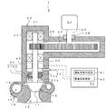
本発明の一実施形態に係る遠心圧縮機1は、例えば100℃〜150℃の熱源を150℃〜180℃に昇温する高温ヒートポンプの遠心圧縮機として用いられるもので、図1に示すように、インペラハウジング部10と、ギヤボックス部(ハウジング)20と、非接触式シール30と、停止時接触シール機構(停止時シール機構)40と、回転数検出センサ(運転状態検出手段)50と、制御部60とを有する。
A
なお、本実施形態において、遠心圧縮機1は高温ヒートポンプに適用されるものとして説明するが、例えば、冷凍機など遠心圧縮機で冷媒を圧縮するあらゆる型式のヒートポンプにも広く適用することができる。
In the present embodiment, the
インペラハウジング部10は、図1に示すように、複数の羽根(不図示)が設けられたインペラ11と、図示しない高温ヒートポンプの蒸発器から冷媒を取り入れる吸入口部12と、インペラ11を収容するインペラ収容部13と、インペラ収容部13に接続された環状のディフューザ流路14と、ディフューザ流路14の外周縁部に接続されたスクロール流路15とを有する。 As shown in FIG. 1, the impeller housing portion 10 houses an impeller 11 provided with a plurality of blades (not shown), a suction port portion 12 for taking in a refrigerant from an evaporator of a high-temperature heat pump (not shown), and the impeller 11. It has an impeller accommodating portion 13, an annular diffuser flow path 14 connected to the impeller accommodating portion 13, and a scroll flow path 15 connected to the outer peripheral edge of the diffuser flow path 14.
インペラ11は、図1に示すように、インペラ回転軸21の端部に取り付けられている。そして、インペラ11は、後述するモータ24の駆動力によりインペラ回転軸21と一体に回転されることで冷媒を径方向の外方へと吐出する。
As shown in FIG. 1, the impeller 11 is attached to an end portion of the
吸入口部12は、図1に示すように、インペラハウジング部10の上流側にインペラ11と同軸上に位置して設けられている。また、吸入口部12は、上流側から下流側に向かって開口面積が次第に小さくなるように形成されている。 As shown in FIG. 1, the suction port portion 12 is provided on the upstream side of the impeller housing portion 10 so as to be coaxial with the impeller 11. Further, the suction port 12 is formed so that the opening area gradually decreases from the upstream side toward the downstream side.
インペラ収容部13は、インペラ11を収容するように、上流側から下流側に向かって開口面積が次第に大きくなるように形成されている。また、インペラ収容部13の上流側は吸入口部12と連通する。 The impeller accommodating portion 13 is formed so that the opening area gradually increases from the upstream side toward the downstream side so as to accommodate the impeller 11. Further, the upstream side of the impeller accommodating portion 13 communicates with the suction port portion 12.
環状のディフューザ流路14は、インペラハウジング部10の下流側側部にインペラ収容部13を取り囲むように形成されている。また、ディフューザ流路14の外周縁部には、冷媒を高温ヒートポンプの凝縮器(不図示)へと吐出するスクロール流路15が接続されている。 The annular diffuser channel 14 is formed on the downstream side portion of the impeller housing portion 10 so as to surround the impeller housing portion 13. Further, a scroll passage 15 for discharging the refrigerant to a condenser (not shown) of a high-temperature heat pump is connected to the outer peripheral edge of the diffuser passage 14.
すなわち、インペラハウジング部10は、インペラ11の回転により、高温ヒートポンプの蒸発器から吸入口部12を介して取り入れた冷媒を、ディフューザ流路14からスクロール流路15へと吐出することで圧縮(昇温・昇圧)するように構成されている。 That is, the impeller housing unit 10 compresses (increases) by discharging the refrigerant taken from the evaporator of the high-temperature heat pump through the suction port 12 to the scroll channel 15 by the rotation of the impeller 11. Temperature and pressure increase).
ギヤボックス部(ハウジング)20は、図1に示すように、インペラ回転軸21のギヤ取り付け側を収容するもので、ギヤボックス部20の内側に設けられた一対の軸受22,23と、ギヤボックス部20の側部に取り付けられたモータ24と、インペラ回転軸21に嵌装された従動ギヤ26と、モータ駆動軸25に嵌装された駆動ギヤ27と、モータ駆動軸25を軸封するエラストマ材からなるモータ軸シール28とを有する。
As shown in FIG. 1, the gear box portion (housing) 20 accommodates the gear mounting side of the impeller
インペラ回転軸21は、図1に示すように、一対の軸受22,23によってギヤボックス部20内に回転自在に軸支されている。また、一対の軸受22,23の間に位置するインペラ回転軸21には、駆動ギヤ27と噛合する従動ギヤ26が嵌装されている。また、軸受22とインペラ11との間に位置するインペラ回転軸21の周面には、後述する非接触式シール30の一部を構成する回転環31が取り付けられる突起部21bが形成されている。さらに、突起部21bと軸受22との間に位置するインペラ回転軸21の周面には、後述する停止時接触シール機構40の一部を構成する環状フランジ21aが形成されている。
As shown in FIG. 1, the
モータ24のモータ駆動軸25は、図1に示すように、ギヤボックス部20の側部から挿通され、図示しない軸受によって回転自在に軸支されている。また、モータ駆動軸25には、従動ギヤ26よりも大径に形成された駆動ギヤ27が嵌装されている。また、モータ駆動軸25が挿通されるギヤボックス部20の側部には、モータ駆動軸25を軸封するモータ軸シール28が設けられている。なお、ギヤボックス部20の内部では、噛合する従動ギヤ26と駆動ギヤ27との摩耗を抑制するため潤滑油が噴射されている。
As shown in FIG. 1, the motor drive shaft 25 of the motor 24 is inserted from the side of the
非接触式シール30は、図1に示すように、インペラ11の背面に隣接するギヤボックス部20内に設けられている。また、非接触式シール30は、インペラ回転軸21側に設けられた回転環31とギヤボックス部20側に設けられた固定環32とを有する。
As shown in FIG. 1, the non-contact type seal 30 is provided in the
回転環31は、突起部21bを介してインペラ回転軸21に固定されている。一方、固定環32は、ギヤボックス部20の内側に形成された取付部20bに図示しないコイルバネを介して軸方向に移動可能に取り付けられている。また、固定環32と対向する回転環31の側面には、図示しない複数のスパイラル溝が設けられている。
The rotary ring 31 is fixed to the impeller
すなわち、非接触式シール30は、回転環31がインペラ回転軸21と一体に回転すると、複数のスパイラル溝により回転環31と固定環32との間に動圧が作用してインペラ回転軸21を軸封するように構成されている。この動圧は、コイルバネの付勢力に抗して固定環32を回転環31から離間させる。一方、インペラ回転軸21の停止時は、回転環31と固定環32とはコイルバネの付勢力により接触する。この接触した状態で、回転環31と固定環32との間にはスパイラル溝による僅かな隙間が存在する。
That is, when the rotating ring 31 rotates integrally with the
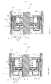
停止時接触シール機構40は、図2(a),(b)に示すように、円筒の中空部を有するシール本体41と、環状の弁体42と、スプリング(付勢手段)43と、押さえ板(開弁手段)44とを有する。
As shown in FIGS. 2A and 2B, the stop-time
シール本体41は、図2(a),(b)に示すように、中空部にインペラ回転軸21を挿通した状態で、非接触式シール30と軸受22との間のギヤボックス部20内に嵌装されている。また、非接触式シール30側(図中X方向側)に位置するシール本体41の内周面の一端部には、環状フランジ21aの頂部に向けて径方向の内方に突出する環状突起41aが設けられている。この環状突起41aの頂部と環状フランジ21aの頂部との間には、環状空間45が形成されている。
As shown in FIGS. 2A and 2B, the
一方、軸受22側(図中Y方向側)に位置するシール本体41の内周面の他端部には、インペラ回転軸21に向けて径方向の内方に突出する支持突起41bが設けられている。この支持突起41bの側部には、スプリング43の一端が係止されている。
On the other hand, a support protrusion 41 b that protrudes inward in the radial direction toward the
また、シール本体41の内部には、図2(a),(b)に示すように、インペラ回転軸21の軸方向(図中X−Y方向)に延びる環状スロット41cが形成されている。この環状スロット41cには、後述する押さえ板44の外周側部44bが摺動可能に挿入される。さらに、環状スロット41cに隣接するシール本体41の内部には、後述する制御部60によって励磁・消磁をコントロールされる電磁石46が設けられている。
Further, as shown in FIGS. 2A and 2B, an annular slot 41 c extending in the axial direction of the impeller rotating shaft 21 (XY direction in the drawing) is formed inside the
環状の弁体42は、図2(a),(b)に示すように、インペラ回転軸21を遊挿した状態で、シール本体41の中空部に摺動自在に収容されている。また、支持突起41bの側部と対向する弁体42の環状側部には、スプリング43の他端が係止されている。すなわち、弁体42は、弁体42と支持突起41bとの間に設けられたスプリング43により、環状フランジ21aと環状突起41aとに向けて付勢されている。
As shown in FIGS. 2A and 2B, the annular valve body 42 is slidably accommodated in the hollow portion of the
また、図2(a),(b)に示すように、環状フランジ21aの側部と対向する弁体42の環状側部には、弁体42と環状フランジ21aとの間の接触面をシールするリング状の内側シール部材(第1シール部材)48が設けられている。さらに、環状突起41aの側部と対向する弁体42の環状側部には、弁体42と環状突起41aとの間の接触面をシールするリング状の外側シール部材(第2シール部材)47が設けられている。すなわち、環状空間45は、弁体42がスプリング43の付勢力により環状フランジ21aと環状突起41aとに接触し、かつ外側シール部材47と内側シール部材48とが接触面をシールすることで閉鎖されるように構成されている(図2(b)参照)。
Further, as shown in FIGS. 2A and 2B, the contact surface between the valve body 42 and the annular flange 21a is sealed on the annular side part of the valve body 42 facing the side part of the annular flange 21a. A ring-shaped inner seal member (first seal member) 48 is provided. Further, a ring-shaped outer seal member (second seal member) 47 that seals the contact surface between the valve body 42 and the annular protrusion 41a is provided on the annular side part of the valve body 42 that faces the side part of the annular protrusion 41a. Is provided. That is, the annular space 45 is closed when the valve body 42 contacts the annular flange 21a and the annular protrusion 41a by the biasing force of the spring 43, and the
押さえ板44は、図2(a),(b)に示すように、環状側部44aと、環状側部44aの外周縁から軸方向に延設された外周側部44bと、環状側部44aの内周縁から軸方向に延設された内周側部44cとを有する。また、外周側部44bは環状スロット41cに摺動可能に挿入され、内周側部44cは環状空間45に挿通されている。そして、押さえ板44は、電磁石46が励磁されると、支持突起41b側(図中Y方向)へと移動する。
As shown in FIGS. 2A and 2B, the holding
すなわち、停止時接触シール機構40は、電磁石46が励磁されると、押さえ板44がスプリング43の付勢力に抗して弁体42を支持突起41b側(図中Y方向)へと押動することで、環状空間45を開放するように構成されている(図2(a)参照)。この時、弁体42と内側シール部材48とは、環状フランジ21aから離間されるので、停止時接触シール機構40とインペラ回転軸21とは非接触状態となる。
That is, when the electromagnet 46 is excited, the stop-time
一方、停止時接触シール機構40は、電磁石46が消磁されると、押さえ板44による弁体42の押動を解除するとともに、弁体42をスプリング43の付勢力により環状突起41a側(図中X方向側)へと移動させる。そして、弁体42が環状フランジ21aと環状突起41aとに接触し、かつ外側シール部材47と内側シール部材48とが接触面をシールして環状空間45を閉鎖することで、インペラ回転軸21を軸封するように構成されている(図2(b)参照)。
On the other hand, when the electromagnet 46 is demagnetized, the
回転数検出センサ50は、図1に示すように、非接触式シール30と停止時接触シール機構40との間のギヤボックス部20内に設けられている。この回転数検出センサ50は、インペラ回転軸21の回転数を検出して後述する制御部60に出力するもので、制御部60と電気配線を介して接続されている。なお、運転状態検出手段として、回転数検出センサ50に替えて、固定環32の回転環31に対する位置を検出する固定環位置検出センサ(不図示)を適用してもよい。
As shown in FIG. 1, the rotation speed detection sensor 50 is provided in the
制御部60は、公知のCPUやROM、RAM、入力ポート、出力ポート等を備え構成されている。また、制御部60には、回転数検出センサ50の出力信号と圧縮機起動盤からの起動信号とがA/D変換された後に入力される。また、制御部60は、図1に示すように、運転状態判定部61と、電磁石制御部62とを一部の機能要素として有する。 The control unit 60 includes a known CPU, ROM, RAM, input port, output port, and the like. Further, the output signal of the rotation speed detection sensor 50 and the start signal from the compressor start panel are input to the control unit 60 after A / D conversion. Moreover, the control part 60 has the driving | running state determination part 61 and the electromagnet control part 62 as a one part function element, as shown in FIG.
運転状態判定部61は、回転数検出センサ50の出力値と起動信号の出力値とに基づいて、遠心圧縮機1の運転状態を判定する。具体的には、回転数検出センサ50の出力値(以下、回転数Nともいう)が0(ゼロ)よりも大きい時は、遠心圧縮機1の運転状態を運転中と判定する。一方、回転数検出センサ50の出力値(回転数N)が0(ゼロ)の時は、遠心圧縮機1の運転状態を停止中と判定する。
The operation state determination unit 61 determines the operation state of the
なお、回転数検出センサ50に替えて固定環位置検出センサを用いる場合は、回転環31と固定環32とが接触状態の時に遠心圧縮機1の運転状態を停止中と判定し、回転環31と固定環32とが離間する非接触状態の時に遠心圧縮機1の運転状態を運転中と判定すればよい。
When a stationary ring position detection sensor is used instead of the rotational speed detection sensor 50, it is determined that the operation state of the
電磁石制御部62は、運転状態判定部61の判定結果に応じて、電磁石46の励磁・消磁をコントロールする。具体的には、遠心圧縮機1の運転状態が運転中と判定された場合は、電磁石制御部62は電磁石46を励磁する制御信号を出力する。すなわち、電磁石46が通電されることで、弁体42は押さえ板44によって支持突起部41b側へと押動される。そして、弁体42が環状フランジ21aと環状突起41aとから離間することで、インペラ回転軸21の軸封は開放される(図2(a)参照)。
The electromagnet controller 62 controls the excitation / demagnetization of the electromagnet 46 according to the determination result of the operation state determination unit 61. Specifically, when it is determined that the operation state of the
一方、遠心圧縮機1の運転状態が停止中と判定された場合は、電磁石制御部62は電磁石46を消磁する制御信号を出力する。すなわち、電磁石46が消磁されることで、押さえ板44による弁体42の押動は解除される。そして、弁体42が環状フランジ21aと環状突起41aとに接触し、かつ外側シール部材47と内側シール部材48とが接触面をシールして環状空間45を閉鎖することで、インペラ回転軸21は軸封される(図2(b)参照)。
On the other hand, when it is determined that the operating state of the
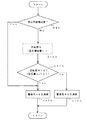
本発明の一実施形態に係る遠心圧縮機1は、以上のように構成されているので、例えば図3に示すフローに従って以下のような制御が行われる。
Since the
ステップ(以下、ステップを単にSと記載する)90では、圧縮機起動盤からの起動信号に基づいて遠心圧縮機1の起動判定が実施される。遠心圧縮機1が起動していないと判定された場合は、S100で運転状態判定部61に回転数検出センサ50によって検出されたインペラ回転軸21の回転数Nが読み込まれる。なお、固定環位置検出センサを用いる場合は、固定環32の回転環31に対する位置L1が検出されて読み込まれる。一方、遠心圧縮機1が起動していると判定された場合はS120へと進む。
In step (hereinafter, the step is simply referred to as S) 90, the start determination of the
S110では、運転状態判定部61によって、遠心圧縮機1の運転状態が確認される。S100で読み込まれた回転数Nが0(ゼロ)よりも大きい場合(N>0)は、遠心圧縮機1の運転状態を運転中と判定してS120へと進む。一方、S100で読み込まれた回転数Nが0(ゼロ)の場合(N=0)は、遠心圧縮機1の運転状態を停止中と判定してS130へと進む。
In S <b> 110, the operation state of the
なお、固定環位置検出センサを用いる場合は、固定環32の回転環31に対する変位量L2を算出すべく、回転環31と固定環32との初期状態の最大距離L0からS100で読み込まれた固定環32の位置L1が減算される(L2=L0−L1)。そして、変位量L2が0(ゼロ)よりも大きい場合は、遠心圧縮機1の運転状態を運転中と判定する。一方、変位量L2が0(ゼロ)の場合は、遠心圧縮機1の運転状態を停止中と判定する。
When the stationary ring position detection sensor is used, in order to calculate the displacement L 2 of the stationary ring 32 with respect to the rotating ring 31, the initial distance L 0 between the rotating ring 31 and the stationary ring 32 is read at S 100. The position L 1 of the stationary ring 32 is subtracted (L 2 = L 0 −L 1 ). When the displacement L 2 is larger than 0 (zero), it is determined that the operation state of the
S120では、電磁石制御部62により電磁石46が励磁される。すなわち、押さえ板44が弁体42を押動し、弁体42が環状フランジ21aと環状突起41aとから離間されて本制御はリターンされる。
In S <b> 120, the electromagnet 46 is excited by the electromagnet controller 62. That is, the holding
一方、S130では、S110で遠心圧縮機1の運転状態が停止中と判定されたことを受けて、電磁石制御部62により電磁石46が消磁される。すなわち、押さえ板44による弁体42の押動が解除され、弁体42が環状フランジ21aと環状突起41aとに接触し、かつ外側シール部材47と内側シール部材48とが接触面をシールして本制御はリターンされる。
On the other hand, in S130, the electromagnet 46 is demagnetized by the electromagnet controller 62 in response to the determination that the operation state of the
上述のような構成により、本発明の一実施形態に係る遠心圧縮機1によれば以下のような作用・効果を奏する。
With the configuration as described above, the
遠心圧縮機1が停止した直後は、高温ヒートポンプのループ内がギヤボックス部20内よりも高温・高圧となり、ループ内の冷媒は、非接触式シール30の回転環31と固定環32との間の僅かな隙間を通って非接触式シール30よりもギヤ26側のギヤボックス部20内へと流れ込もうとする。
Immediately after the
ここで、本実施形態に係る遠心圧縮機1では、遠心圧縮機1が停止すると、電磁石46が消磁されて、押さえ板44による弁体42の押動は解除される。そして、弁体42がスプリング43の付勢力により環状フランジ21aと環状突起41aとに接触し、かつ外側シール部材47と内側シール部材48とが接触面をシールして環状空間45を閉鎖することで、インペラ回転軸21は軸封される。
Here, in the
したがって、停止時接触シール機構40によって、遠心圧縮機1の停止と同時にインペラ回転軸21が確実に軸封されるので、冷媒が低圧側である非接触式シール30よりもギヤ26側のギヤボックス部20内に流れ込むことを効果的に抑止することができる。
Therefore, since the
また、冷媒の非接触式シール30よりもギヤ26側のギヤボックス部20内への流れ込みが抑止されるので、例えば、ヒートポンプに潤滑油への溶融性が高い冷媒や、シールとして用いられるエラストマ材への浸食性が高い冷媒を用いた場合においても、冷媒の溶融による潤滑油の劣化や、冷媒の浸食によるモータ軸シール28の劣化を効果的に防止することができる。
Further, since the refrigerant is prevented from flowing into the
また、インペラ回転軸21は、遠心圧縮機1の運転時は非接触式シール30で軸封され、遠心圧縮機1の停止時は停止時接触シール機構40で確実に軸封される。
The
したがって、ギヤボックス部20やモータ軸シール28に不具合が発生した場合においても、非接触式シール30よりもギヤ26側のギヤボックス部20内から高温ヒートポンプのループ内に空気や潤滑油が漏出することを効果的に防止することができる。
Therefore, even when a malfunction occurs in the
また、停止時接触シール機構40は、非接触式シール30にシールガス等を供給することなく、シール本体41、弁体42、スプリング43、押さえ板44等の簡素な構成でインペラ回転軸21を確実に軸封することができるので、遠心圧縮機1のメンテナンスや管理の容易化も図られる。
Further, the
なお、本発明は、上述の実施形態に限定されるものではなく、本発明の趣旨を逸脱しない範囲で、適宜変形して実施することが可能である。 In addition, this invention is not limited to the above-mentioned embodiment, In the range which does not deviate from the meaning of this invention, it can change suitably and can implement.
上述の実施形態において、外側シール部材47と内側シール部材48とは弁体42の環状側部に設けられるものとして説明したが、内側シール部材48を環状フランジ21aの側部に設け、外側シール部材47を環状突起41aの側部に設けてもよい。
In the above-described embodiment, the
また、付勢手段は必ずしもスプリング43である必要はなく、弁体42を付勢するものであれば、板バネや油圧シリンダなどを適用してもよい。付勢手段に油圧シリンダを用いる場合は、開弁手段と兼用することもできる。 Further, the biasing means is not necessarily the spring 43, and a leaf spring, a hydraulic cylinder, or the like may be applied as long as it biases the valve body 42. When a hydraulic cylinder is used as the biasing means, it can also be used as the valve opening means.
1 遠心圧縮機
11 インペラ
20 ギヤボックス部(ハウジング)
21 インペラ回転軸(回転軸)
21a 環状フランジ
30 非接触式シール
40 停止時接触シール機構(停止時シール機構)
41a 環状突起
42 弁体
43 スプリング(付勢手段)
44 押さえ板(開弁手段)
50 回転数検出センサ(運転状態検出手段)
1 Centrifugal Compressor 11
21 Impeller rotating shaft (Rotating shaft)
21a Annular flange 30
41a annular projection 42 valve element 43 spring (biasing means)
44 Holding plate (Valve opening means)
50 Rotational speed detection sensor (operating state detection means)
Claims (3)
前記遠心圧縮機の運転状態を検出する運転状態検出手段と、
前記非接触式シールよりもギヤ側の前記ハウジング内に設けられ、前記運転状態検出手段の検出に応じて、前記遠心圧縮機の運転時に前記回転軸から離間し、前記遠心圧縮機の停止時に前記回転軸と接触して軸封する停止時シール機構と、を備える
ことを特徴とする遠心圧縮機。 A centrifugal compressor having a non-contact seal that seals the rotating shaft in a housing that houses a gear mounting side of the rotating shaft that has an impeller attached to one end and a gear attached to the other end,
An operation state detecting means for detecting an operation state of the centrifugal compressor;
Provided in the housing on the gear side with respect to the non-contact type seal, separated from the rotating shaft during operation of the centrifugal compressor according to detection of the operation state detection means, and when the centrifugal compressor is stopped A centrifugal compressor characterized by comprising: a sealing mechanism for stopping when the shaft is sealed in contact with the rotating shaft.
前記非接触式シールよりもギヤ取り付け側に位置する前記回転軸の周面に設けられた環状フランジと、
前記非接触式シールよりもギヤ側の前記ハウジングの内側面から前記環状フランジに向けて突出するとともに、前記環状フランジとの間に環状空間を形成する環状突起と、
前記環状フランジと前記環状突起とに接触して前記環状空間を閉鎖する弁体と、
前記弁体を前記環状フランジと前記環状突起とに向けて付勢して接触させる付勢手段と、
前記運転状態検出手段の検出に応じて、前記遠心圧縮機の運転時に前記付勢手段の付勢力に抗して前記弁体を前記環状フランジと前記環状突起とから離間させせる開弁手段と、を備える
ことを特徴とする請求項1記載の遠心圧縮機。 The stopping seal mechanism is
An annular flange provided on the peripheral surface of the rotating shaft located on the gear mounting side with respect to the non-contact type seal;
An annular protrusion that protrudes from the inner surface of the housing closer to the gear than the non-contact seal toward the annular flange, and forms an annular space between the annular flange;
A valve body that contacts the annular flange and the annular protrusion to close the annular space;
Biasing means for biasing and contacting the valve body toward the annular flange and the annular projection;
A valve opening means for separating the valve body from the annular flange and the annular protrusion against the urging force of the urging means during operation of the centrifugal compressor in response to detection of the operating state detecting means; The centrifugal compressor according to claim 1, comprising:
前記弁体と前記環状フランジとの間の接触面をシールする第1シール部材と、
前記弁体と前記環状突起との間の接触面をシールする第2シール部材と、をさらに備える
ことを特徴とする請求項2記載の遠心圧縮機。 The stopping seal mechanism is
A first seal member for sealing a contact surface between the valve body and the annular flange;
The centrifugal compressor according to claim 2, further comprising: a second seal member that seals a contact surface between the valve body and the annular protrusion.
Priority Applications (1)
| Application Number | Priority Date | Filing Date | Title |
|---|---|---|---|
| JP2011001943A JP5740985B2 (en) | 2011-01-07 | 2011-01-07 | Centrifugal compressor |
Applications Claiming Priority (1)
| Application Number | Priority Date | Filing Date | Title |
|---|---|---|---|
| JP2011001943A JP5740985B2 (en) | 2011-01-07 | 2011-01-07 | Centrifugal compressor |
Publications (2)
| Publication Number | Publication Date |
|---|---|
| JP2012144994A true JP2012144994A (en) | 2012-08-02 |
| JP5740985B2 JP5740985B2 (en) | 2015-07-01 |
Family
ID=46788820
Family Applications (1)
| Application Number | Title | Priority Date | Filing Date |
|---|---|---|---|
| JP2011001943A Expired - Fee Related JP5740985B2 (en) | 2011-01-07 | 2011-01-07 | Centrifugal compressor |
Country Status (1)
| Country | Link |
|---|---|
| JP (1) | JP5740985B2 (en) |
Cited By (1)
| Publication number | Priority date | Publication date | Assignee | Title |
|---|---|---|---|---|
| JP2014109423A (en) * | 2012-12-04 | 2014-06-12 | Ihi Corp | Heat medium circulation system and method for operating heat medium circulation system |
Citations (4)
| Publication number | Priority date | Publication date | Assignee | Title |
|---|---|---|---|---|
| JPS54147348A (en) * | 1978-05-11 | 1979-11-17 | Mitsubishi Electric Corp | Axle sealing device |
| JPS5975597U (en) * | 1982-10-28 | 1984-05-22 | 株式会社荏原製作所 | turbo compressor |
| JPS60159272U (en) * | 1984-04-02 | 1985-10-23 | 三菱重工業株式会社 | Shaft sealing device |
| JPS6212048U (en) * | 1985-07-05 | 1987-01-24 |
-
2011
- 2011-01-07 JP JP2011001943A patent/JP5740985B2/en not_active Expired - Fee Related
Patent Citations (4)
| Publication number | Priority date | Publication date | Assignee | Title |
|---|---|---|---|---|
| JPS54147348A (en) * | 1978-05-11 | 1979-11-17 | Mitsubishi Electric Corp | Axle sealing device |
| JPS5975597U (en) * | 1982-10-28 | 1984-05-22 | 株式会社荏原製作所 | turbo compressor |
| JPS60159272U (en) * | 1984-04-02 | 1985-10-23 | 三菱重工業株式会社 | Shaft sealing device |
| JPS6212048U (en) * | 1985-07-05 | 1987-01-24 |
Cited By (1)
| Publication number | Priority date | Publication date | Assignee | Title |
|---|---|---|---|---|
| JP2014109423A (en) * | 2012-12-04 | 2014-06-12 | Ihi Corp | Heat medium circulation system and method for operating heat medium circulation system |
Also Published As
| Publication number | Publication date |
|---|---|
| JP5740985B2 (en) | 2015-07-01 |
Similar Documents
| Publication | Publication Date | Title |
|---|---|---|
| JP4516123B2 (en) | Variable displacement rotary compressor and method of operating the same | |
| JP5197157B2 (en) | Screw fluid machine | |
| JP5817760B2 (en) | Scroll compressor | |
| JPWO2018051867A1 (en) | mechanical seal | |
| JPWO2015136979A1 (en) | Refrigeration cycle equipment | |
| JP4833882B2 (en) | Screw fluid machine | |
| JP5736780B2 (en) | Centrifugal compressor | |
| WO2000065260A1 (en) | Mechanical seal for compressor | |
| JP2008215107A (en) | Compressor | |
| JP6151382B2 (en) | Multistage electric centrifugal compressor | |
| JP5740985B2 (en) | Centrifugal compressor | |
| WO2016080014A1 (en) | Seal gas supply control method, seal gas supply control appratus, and rotary machine | |
| JP2008185082A (en) | Gas seal device | |
| JP2002022033A (en) | Labyrinth seals and fluid machinery | |
| JP2015034506A (en) | Scroll type compressor | |
| EP3263902B1 (en) | Screw compressor | |
| JP5625886B2 (en) | Centrifugal compressor | |
| JP2019210869A (en) | Pump device, impeller interval adjusting method for pump device | |
| JP2008184926A (en) | Reciprocating compressor | |
| JP2000193099A (en) | Mechanical seal for gas compressor | |
| JP2019065706A (en) | Open type compressor | |
| JP2009264271A (en) | Thrust bearing mechanism in turbocharger | |
| JP2003343472A (en) | Shaft seal structure of vacuum pump | |
| JP4234480B2 (en) | Control device for electric gas compressor | |
| KR20210028466A (en) | Apparatus for a Formation of Back-Pressure in Electric Compressor and Method Employing the Same |
Legal Events
| Date | Code | Title | Description |
|---|---|---|---|
| A621 | Written request for application examination |
Free format text: JAPANESE INTERMEDIATE CODE: A621 Effective date: 20131126 |
|
| A977 | Report on retrieval |
Free format text: JAPANESE INTERMEDIATE CODE: A971007 Effective date: 20140828 |
|
| A131 | Notification of reasons for refusal |
Free format text: JAPANESE INTERMEDIATE CODE: A131 Effective date: 20140902 |
|
| A521 | Request for written amendment filed |
Free format text: JAPANESE INTERMEDIATE CODE: A523 Effective date: 20141008 |
|
| TRDD | Decision of grant or rejection written | ||
| A01 | Written decision to grant a patent or to grant a registration (utility model) |
Free format text: JAPANESE INTERMEDIATE CODE: A01 Effective date: 20150331 |
|
| A61 | First payment of annual fees (during grant procedure) |
Free format text: JAPANESE INTERMEDIATE CODE: A61 Effective date: 20150413 |
|
| R151 | Written notification of patent or utility model registration |
Ref document number: 5740985 Country of ref document: JP Free format text: JAPANESE INTERMEDIATE CODE: R151 |
|
| R250 | Receipt of annual fees |
Free format text: JAPANESE INTERMEDIATE CODE: R250 |
|
| R250 | Receipt of annual fees |
Free format text: JAPANESE INTERMEDIATE CODE: R250 |
|
| LAPS | Cancellation because of no payment of annual fees |