JP2012144689A - Silicate phosphor and method for producing the same - Google Patents
Silicate phosphor and method for producing the same Download PDFInfo
- Publication number
- JP2012144689A JP2012144689A JP2011119130A JP2011119130A JP2012144689A JP 2012144689 A JP2012144689 A JP 2012144689A JP 2011119130 A JP2011119130 A JP 2011119130A JP 2011119130 A JP2011119130 A JP 2011119130A JP 2012144689 A JP2012144689 A JP 2012144689A
- Authority
- JP
- Japan
- Prior art keywords
- emission intensity
- excitation wavelength
- powder
- phosphor
- silicate phosphor
- Prior art date
- Legal status (The legal status is an assumption and is not a legal conclusion. Google has not performed a legal analysis and makes no representation as to the accuracy of the status listed.)
- Granted
Links
Images


Landscapes
- Luminescent Compositions (AREA)
- Led Device Packages (AREA)
Abstract
【課題】近紫外LEDの発光波長である400nm前後で励起されて強発光し、励起波長の変化による発光強度変化が少ない青色蛍光体と、その蛍光体を簡便に得る製造方法を提供する。
【解決手段】Ba1−xEuxZrSiyO3+2y(但し、0.001≦x≦0.5、2.5≦y≦3)の組成式で表されるシリケート蛍光体であって、粉末X線回折パターンにおいて、BaZrSi3O9の回折パターンを有し、励起波長400nmにおける発光強度が励起波長300nmにおける発光強度の40%以上、励起波長380nm〜420nmの範囲において、(Iex 380nm−Iex 420nm)/Iex 380nm×100の式で表される発光強度変化率が30%以下であることを特徴とする。
【選択図】図3The present invention provides a blue phosphor that emits strong light when excited at around 400 nm, which is the emission wavelength of a near-ultraviolet LED, and has a small change in emission intensity due to a change in excitation wavelength, and a production method for easily obtaining the phosphor.
A silicate phosphor represented by a composition formula of Ba 1-x Eu x ZrSi y O 3 + 2y (where 0.001 ≦ x ≦ 0.5, 2.5 ≦ y ≦ 3), and powder The X-ray diffraction pattern has a BaZrSi 3 O 9 diffraction pattern, and the emission intensity at an excitation wavelength of 400 nm is 40% or more of the emission intensity at an excitation wavelength of 300 nm, and the excitation wavelength ranges from 380 nm to 420 nm (I ex 380 nm −I ex 420 nm ) / I ex 380 nm × 100 The emission intensity change rate represented by the formula is 30% or less.
[Selection] Figure 3
Description
本発明は、近紫外から可視領域の光による励起で高輝度の青色発光を示すシリケート蛍光体およびその製造方法に関する。 The present invention relates to a silicate phosphor that exhibits high-luminance blue light emission when excited by light in the near ultraviolet to visible region, and a method for producing the same.
白色LEDは青色または近紫外LED(LD)と、蛍光体を組み合わせて作製される。白色LEDは、発光効率が低かったため携帯電話などのバックライト用途を中心に開発されてきたが、近年、発光効率の増加と共に次世代照明として注目を集めている。
白色LEDを構成する方式としては、青色LEDと黄色蛍光体を組み合わせる方式、近紫外LEDと青、緑、赤色蛍光体を組み合わせる方式などが提案されている。
近紫外LED励起方式では、LEDの発光波長である400nm前後で励起されて効率良く発光する青色系蛍光体が必要となり、従来の蛍光ランプで用いられてきた(Ca,Sr)5(PO4)3Cl:EuやBaMgAl10O17:Eu(BAM)などが改良されて用いられている。
例えば、非特許文献1には、近紫外LED励起方式用に改良されたBAMの励起スペクトルと発光スペクトルが記載されている。
The white LED is manufactured by combining a blue or near ultraviolet LED (LD) and a phosphor. White LEDs have been developed mainly for backlight applications such as cellular phones because of their low luminous efficiency, but in recent years, they have attracted attention as next-generation lighting as the luminous efficiency increases.
As a method for configuring the white LED, a method of combining a blue LED and a yellow phosphor, a method of combining a near ultraviolet LED and a blue, green, and red phosphor have been proposed.
The near-ultraviolet LED excitation method requires a blue phosphor that is excited at around 400 nm, which is the emission wavelength of the LED, to emit light efficiently, and has been used in conventional fluorescent lamps (Ca, Sr) 5 (PO 4 ). 3 Cl: Eu or BaMgAl 10 O 17: like Eu (BAM) is used is improved.
For example, Non-Patent
近紫外励起で青色発光する蛍光体のひとつとして、BaZrSi3O9:Euが知られている。非特許文献1には、Ba0.99ZrSi3O9:0.01Euが記載されている。
また、特許文献1には(Ba,Sr)0.99ZrSi3O9:0.01Euが開示されており、特許文献2には(Ba(1−x−y)SrxEuy)(Sn1−zZrz)Si3O9なる組成としてBaサイトをSrで、ZrサイトをSnで置換することによって、近紫外励起において発光強度が増加することが開示されている。
BaZrSi 3 O 9 : Eu is known as one of phosphors that emit blue light under near ultraviolet excitation. Non-Patent
しかしながら、非特許文献1に記載されているBAMの励起スペクトルを見ると、励起強度は380nm程度をピークとして400nm前後で急激に減少している、また、励起強度は、その波長での発光強度に対応するため、このことは励起波長の変化による発光強度の変化が大きいことを示している(類推ではあるが、380nm〜420nmでの発光強度変化は、グラフから60%前後と見られる)。
このように蛍光体の励起波長に対する発光強度の急激な変化があると、励起源である紫外LEDの発光波長のばらつきによる青色発光強度のばらつきも大きくなり、白色LEDの色合いや発光強度のばらつきに繋がるため好ましくない。
However, looking at the excitation spectrum of BAM described in
In this way, when there is a sudden change in the emission intensity with respect to the excitation wavelength of the phosphor, the variation in the blue emission intensity due to the variation in the emission wavelength of the ultraviolet LED that is the excitation source also increases, resulting in variations in the color and emission intensity of the white LED. Since it connects, it is not preferable.
非特許文献2、および特許文献1に記載されているBa0.99ZrSi3O9:0.01Euは、その励起スペクトル(図4(b)例2;特許文献1、Fig.3、曲線6参照)を見ると、近紫外領域において励起強度が急激に低下し、励起波長400nm付近での発光強度が低いことは明らかである(なお、特許文献1の励起スペクトルから、380nm〜420nmでの発光強度変化は35%前後、励起波長300nmにおける発光強度は励起波長400nmにおける発光強度の35%前後と類推される)。
また、BaCO3、ZrO2、SiO2、Eu2O3の混合物を、窒素−水素混合ガス中で熱処理する固相反応によって形成されているが、このような固相反応の場合、Euが均一に分散した主相純度の高い蛍光体を得ることは難しく、固相反応を十分に進行させるために、一般的には高温長時間の熱処理や繰り返し焼成が行われるが、長時間の熱処理や繰り返して行う熱処理は工業的には好ましくない。また、どちらも粉砕を必要とするため、ダメージによって輝度が低下してしまう問題を抱えている。
Ba 0.99 ZrSi 3 O 9 : 0.01 Eu described in
Further, it is formed by a solid phase reaction in which a mixture of BaCO 3 , ZrO 2 , SiO 2 , Eu 2 O 3 is heat-treated in a nitrogen-hydrogen mixed gas. In such a solid phase reaction, Eu is uniform. It is difficult to obtain a phosphor having a high main phase purity dispersed in the material. Generally, high-temperature long-time heat treatment and repeated firing are performed to sufficiently advance the solid-phase reaction. The heat treatment performed in this manner is not industrially preferable. Moreover, since both require grinding | pulverization, it has the problem that a brightness | luminance falls by damage.
さらに、特許文献2の比較例として開示されているBa0.98ZrSi3O9:0.02Euは、400nm前後での励起スペクトルは開示されておらず、また発光強度も相対値であり絶対値の比較が困難である。しかしながら、非特許文献2に開示されている製造法と、ほぼ同じ作り方(固相法)をしているため、励起波長400nm付近での発光強度変化が大きく、発光強度も不十分であると言える。また、特許文献2の実施例においては、BaサイトのSr置換により、例えば365nm励起での相対輝度が比較例であるBa0.98ZrSi3O9:0.02Euの1.9倍強まで上昇しているが、上述したように、Ba0.98ZrSi3O9:0.02Euそのもの強度が低いため、実用的に十分な輝度を有しているとは言えない。
Further, Ba 0.98 ZrSi 3 O 9 : 0.02 Eu disclosed as a comparative example of
このような状況の中で、本発明の目的は、近紫外LEDの発光波長である400nm前後で励起されて強発光し、励起波長の変化による発光強度変化が少ない青色蛍光体と、その蛍光体を簡便に得る製造方法を提供することにある。 Under such circumstances, an object of the present invention is to provide a blue phosphor that emits strong light when excited at around 400 nm, which is the emission wavelength of a near-ultraviolet LED, and has little emission intensity change due to a change in excitation wavelength, and the phosphor. It is providing the manufacturing method which obtains easily.
本発明者らは、上記課題を解決するために検討を重ねた結果、Ba1−xEuxZrSiyO3+2yの組成式で表されるシリケート蛍光体において、x並びにyが、0.001≦x≦0.5、2.5≦y≦3の範囲にあり、粉末X線回折パターンにおいてBaZrSi3O9型の回折パターンを持つものは、400nm付近の励起波長における発光強度が高く、励起波長に対する発光強度の変化率が小さいことを見出した。さらに、Ba1−xEuxZrSiyO3+2yの組成式においてx並びにyが、0.001≦x≦0.5、3<y≦6の範囲にあり、X線回折パターンにおいてBaZrSi3O9型(ICDD29−0214)の回折パターンを有し、かつブラッグ角度(2θ)の22°付近にSiO2クリストバライト由来のピークを持つものは、より発光強度が高いことを見出した。 As a result of repeated studies to solve the above problems, the present inventors have found that in the silicate phosphor represented by the composition formula of Ba 1-x Eu x ZrSi y O 3 + 2y , x and y are 0.001 ≦ x ≦ 0.5, 2.5 ≦ y ≦ 3, and a powder X-ray diffraction pattern having a BaZrSi 3 O 9 type diffraction pattern has a high emission intensity at an excitation wavelength near 400 nm, and the excitation wavelength It has been found that the rate of change of the emission intensity with respect to is small. Furthermore, in the composition formula of Ba 1-x Eu x ZrSi y O 3 + 2y , x and y are in the range of 0.001 ≦ x ≦ 0.5 and 3 <y ≦ 6. In the X-ray diffraction pattern, BaZrSi 3 O 9 It was found that those having a diffraction pattern of the type (ICDD29-0214) and having a peak derived from SiO 2 cristobalite in the vicinity of 22 ° of the Bragg angle (2θ) have higher emission intensity.
また、上記したような特徴を持つシリケート蛍光体は、構成成分であるBa、Zr、Eu、Siの各金属成分を水溶液として混合し、さらにオキシカルボン酸を加えた混合液を加熱することによって、その混合液をゲル化し、その後乾燥して形成したゲル体を、ゲル体に含まれる有機物を除去するために、大気中で焼成して、構成成分が均一に分布した前駆体を得、次いで得られた前駆体を還元雰囲気中で熱処理することにより、BaZrSi3O9結晶相を得ると同時に、EuをBaサイトに還元ドープしてシリケート蛍光体粉末を形成する工程によって、より高輝度に発光するシリケート蛍光体が簡便に得られることを見出した。さらに、得られた蛍光体粉末を、再度還元性雰囲気で熱処理することで、発光強度がさらに増加することを見出し、本発明を完成するに至った。 In addition, the silicate phosphor having the above-described characteristics is obtained by mixing the constituent metal components Ba, Zr, Eu, and Si as an aqueous solution, and further heating the mixed liquid to which oxycarboxylic acid is added. In order to remove organic substances contained in the gel body, the gel body formed by gelling the mixed liquid and then dried is baked in the air to obtain a precursor in which constituent components are uniformly distributed, and then obtained. By heat-treating the obtained precursor in a reducing atmosphere, a BaZrSi 3 O 9 crystal phase is obtained, and at the same time, Eu is reduced doped into Ba sites to form silicate phosphor powder, which emits light with higher brightness. It has been found that a silicate phosphor can be easily obtained. Furthermore, the obtained phosphor powder was again heat-treated in a reducing atmosphere, whereby the emission intensity was further increased, and the present invention was completed.
即ち、本発明の第1の発明は、Ba1−xEuxZrSiyO3+2y(但し、0.001≦x≦0.5、2.5≦y≦3)の組成式で表されるシリケート蛍光体であって、粉末X線回折パターンにおいて、BaZrSi3O9の回折パターンを有し、励起波長400nmにおける発光強度が励起波長300nmにおける発光強度の40%以上、励起波長380nm〜420nmの範囲において、下記(1)式で表される発光強度変化率が30%以下、
であることを特徴とするものである。
That is, the first invention of the present invention is a silicate represented by a composition formula of Ba 1-x Eu x ZrSi y O 3 + 2y (where 0.001 ≦ x ≦ 0.5, 2.5 ≦ y ≦ 3). A phosphor having a diffraction pattern of BaZrSi 3 O 9 in a powder X-ray diffraction pattern, wherein the emission intensity at an excitation wavelength of 400 nm is 40% or more of the emission intensity at an excitation wavelength of 300 nm, and the excitation wavelength ranges from 380 nm to 420 nm. The emission intensity change rate represented by the following formula (1) is 30% or less,
It is characterized by being.

また、本発明の第2の発明は、Ba1−xEuxZrSiyO3+2y(但し、0.001≦x≦0.5、3<y≦6)の組成式で表されるシリケート蛍光体であって、粉末X線回折パターンにおいて、BaZrSi3O9の回折パターンを有し、かつ、ブラッグ角度(2θ)の22°付近にSiO2(クリストバライト)由来のピークを有し、励起波長400nmにおける発光強度が励起波長300nmにおける発光強度の40%以上で、励起波長380nm〜420nmの範囲において、前記(1)式で表される発光強度変化率が30%以下であることを特徴とするものである。 Further, the second invention of the present invention is a silicate phosphor represented by a composition formula of Ba 1-x Eu x ZrSi y O 3 + 2y (where 0.001 ≦ x ≦ 0.5, 3 <y ≦ 6). In the powder X-ray diffraction pattern, it has a diffraction pattern of BaZrSi 3 O 9 and has a peak derived from SiO 2 (cristobalite) in the vicinity of 22 ° of the Bragg angle (2θ) at an excitation wavelength of 400 nm. The emission intensity is 40% or more of the emission intensity at an excitation wavelength of 300 nm, and the emission intensity change rate represented by the formula (1) is 30% or less in the excitation wavelength range of 380 nm to 420 nm. is there.
更に、本発明の第3の発明は、Ba1−xEuxZrSiyO3+2y(但し、0.001≦x≦0.5、2.5≦y≦6)の組成式で表されるシリケート蛍光体の製造方法であって、下記の工程1から工程3を含むことを特徴とするものである。
工程1:構成成分の中の金属成分であるBa、Zr、Eu、Si元素を水溶液として混合し、さらにオキシカルボン酸を加えた混合液を加熱して前記混合液をゲル化し、次いで乾燥してゲル体を形成する工程。
工程2:工程1で作製したゲル体を、大気中で焼成することによりゲル体に含まれる有機物を除去して、構成成分が均一に分布した前駆体を作製する工程。
工程3:工程2で作製した前駆体を、還元雰囲気中で熱処理することにより、BaZrSi3O9結晶相を得ると同時に、EuをBaサイトに還元ドープして高輝度に発光するシリケート蛍光体粉末を形成する工程。
Furthermore, the third invention of the present invention is a silicate represented by a composition formula of Ba 1-x Eu x ZrSi y O 3 + 2y (where 0.001 ≦ x ≦ 0.5, 2.5 ≦ y ≦ 6). A method for manufacturing a phosphor, comprising the
Step 1: Ba, Zr, Eu, and Si elements, which are metal components in the constituent components, are mixed as an aqueous solution, and the mixed solution to which oxycarboxylic acid is added is heated to gel the mixed solution, and then dried. A step of forming a gel body.
Step 2: The step of producing a precursor in which constituent components are uniformly distributed by removing the organic matter contained in the gel by baking the gel produced in
Step 3: A silicate phosphor powder that obtains a BaZrSi 3 O 9 crystal phase by heat-treating the precursor prepared in
また、本発明の第4の発明は、前記工程3で作製されたシリケート蛍光粉末を、さらに還元雰囲気下で熱処理する工程を含むことを特徴とするものである。
また、本発明の第5の発明は、前記工程3で作製されたシリケート蛍光粉末を、さらに大気雰囲気下で、500〜1500℃の温度で熱処理する工程を含むことを特徴とするものである。
The fourth invention of the present invention is characterized by further comprising a step of heat-treating the silicate fluorescent powder produced in the
The fifth invention of the present invention is characterized in that it further includes a step of heat-treating the silicate fluorescent powder produced in the
本発明によれば、近紫外LEDの発光波長である400nm前後で効率良く励起され、かつ励起波長に対する発光強度変化が小さいシリケート蛍光体を提供することができ、そのようなシリケート蛍光体をより簡便な方法で製造することができる。 According to the present invention, it is possible to provide a silicate phosphor that is efficiently excited at around 400 nm, which is the emission wavelength of a near-ultraviolet LED, and has a small change in emission intensity with respect to the excitation wavelength. Can be manufactured by a simple method.
以下、本発明を実施するための形態を詳細に説明する。
本発明はBa1−xEuxZrSiyO3+2yの組成式で表される蛍光体であり、x並びにyが、0.001≦x≦0.5、2.5≦y≦6の組成範囲にあることを第一の特徴とする。
xはより好ましくは、0.005≦x≦0.2の範囲にあることが好ましい。最適なEu濃度はyの値により異なるが、x<0.005では賦活材であるEuの濃度が低すぎて発光強度が低下する。また、x>0.2では濃度消光によって発光強度が低下する。
Hereinafter, embodiments for carrying out the present invention will be described in detail.
The present invention is a phosphor represented by a composition formula of Ba 1-x Eu x ZrSi y O 3 + 2y , wherein x and y are in a composition range of 0.001 ≦ x ≦ 0.5 and 2.5 ≦ y ≦ 6. This is the first feature.
x is more preferably in the range of 0.005 ≦ x ≦ 0.2. The optimum Eu concentration varies depending on the value of y. However, when x <0.005, the concentration of Eu as an activator is too low, and the emission intensity decreases. In addition, when x> 0.2, the emission intensity decreases due to concentration quenching.
y<2.5ではSiO2プアーになりすぎて異相(Ba2Zr2Si3O12)が生成し、発光強度が低下する。
y>3とすることにより発光強度が増加する。これはSiO2を理論量よりも過剰にすることで、Eu2O3が還元ドープされやすくなることによると考えられる。
また、SiO2を理論量よりも過剰にすることで、熱処理中に、より結晶成長しやすくなっていると考えられる。SiO2をさらに過剰にした場合、XRDパターンは後述するように、BaZrSi3O9とSiO2(クリストバライト)とが検出される。
If y <2.5, it becomes too SiO 2 poor and a different phase (Ba 2 Zr 2 Si 3 O 12 ) is generated, resulting in a decrease in emission intensity.
By setting y> 3, the emission intensity increases. This is considered to be because Eu 2 O 3 is easily reduced and doped by making SiO 2 excessive from the theoretical amount.
Moreover, it is considered that the crystal growth is facilitated during the heat treatment by making SiO 2 excessive from the theoretical amount. When SiO 2 is further excessive, BaZrSi 3 O 9 and SiO 2 (cristobalite) are detected in the XRD pattern as will be described later.
最終的に得られたシリケート蛍光体中に存在するSiO2は発光に寄与しないため、最適なSiO2量は、SiO2過剰にすることによる熱処理の過程での発光強度が増加する効果と、過剰SiO2が残留することで発光に寄与する相の比率の低下による発光強度の低下と、発光強度への影響のバランスで決定される。
y>6では発光強度増加への効果はほとんどなくなる。ただし、SiO2を蛍光体中により多く残留させることを目的とする場合は、y>6の組成とすることもできるが、発光強度の低下を回避することは困難である。
Since the SiO 2 present in the finally obtained silicate phosphor does not contribute to light emission, the optimum amount of SiO 2, the effect of the emission intensity in the course of heat treatment due to the SiO 2 excess is increased, excessive It is determined by the balance between the decrease in the emission intensity due to the decrease in the ratio of the phase contributing to the emission due to the remaining SiO 2 and the influence on the emission intensity.
When y> 6, there is almost no effect on the increase in emission intensity. However, when the purpose is to leave more SiO 2 in the phosphor, the composition can satisfy y> 6, but it is difficult to avoid a decrease in emission intensity.
また、発光強度や励起波長、発光波長を改善する目的でBa1−xEuxZrSiyO3+2yの組成式のBaの一部をSr、Ca、Mgなどで、Zrの一部をTi、Hf、Snなどで、Siの一部をGeで置換することができる。 For the purpose of improving the emission intensity, the excitation wavelength, and the emission wavelength, part of Ba in the composition formula of Ba 1-x Eu x ZrSi y O 3 + 2y is Sr, Ca, Mg, etc., and part of Zr is Ti, Hf. , Sn, etc., a part of Si can be replaced with Ge.
本発明のシリケート蛍光体は、粉末X線回折パターンが、「国際回折データセンター」が発行する粉末回折データ:ICDD(29−0214)に記載されているBaZrSi3O9に帰属する回折パターンを示すことも特徴である。
発光特性に影響しない微量であれば、ZrO2やBaシリケート、Zrシリケートなどを異相成分として含むことができる。また、組成をSiO2リッチとした場合は、ブラッグ角度(2θ)の22°付近にSiO2(クリストバライト)由来のピークが同時に現れる特徴を有する。
In the silicate phosphor of the present invention, the powder X-ray diffraction pattern shows a diffraction pattern attributed to BaZrSi 3 O 9 described in powder diffraction data: ICDD (29-0214) issued by “International Diffraction Data Center”. It is also a feature.
If it is a trace amount that does not affect the light emission characteristics, ZrO 2 , Ba silicate, Zr silicate, and the like can be included as heterogeneous components. Further, when the composition is SiO 2 rich, there is a feature that a peak derived from SiO 2 (cristobalite) appears at the same time around 22 ° of the Bragg angle (2θ).
本発明のシリケート蛍光体は、励起波長400nmにおける発光強度が、励起波長300nmにおける発光強度の40%以上であり、かつ、励起波長380nm〜420nmの範囲における発光強度の変化率が30%以下である特徴も有する。
したがって、近紫外LEDの発光波長である400nm前後で励起されて強発光し、かつ励起波長の変化による発光強度の変化率が小さいことにより、近紫外LED励起方式の青色蛍光体として好適に使用することができる。
The silicate phosphor of the present invention has an emission intensity at an excitation wavelength of 400 nm of 40% or more of an emission intensity at an excitation wavelength of 300 nm, and a change rate of the emission intensity in an excitation wavelength range of 380 nm to 420 nm is 30% or less. It also has features.
Therefore, it is excited as a near-ultraviolet LED emission wavelength around 400 nm and emits strong light, and the rate of change in emission intensity due to the change in excitation wavelength is small, so it is suitably used as a near-ultraviolet LED excitation-type blue phosphor. be able to.
次に、本発明のシリケート蛍光体の製造方法について説明する。
本発明のシリケート蛍光体は、その構成成分であるBa、Zr、Eu、Siが、均一に含有することが重要であるため、下記のような工程を含む製造方法を用いることにより、発光強度の高い蛍光体をより簡便に作製することができる。
Next, a method for producing the silicate phosphor of the present invention will be described.
Since it is important for the silicate phosphor of the present invention that the constituent components Ba, Zr, Eu, and Si are contained uniformly, by using a manufacturing method including the following steps, the emission intensity can be increased. A high phosphor can be produced more easily.
[工程1]
構成成分の中の金属成分であるBa、Zr、Eu、Siを水溶液として混合し、さらにオキシカルボン酸を加えて加熱してゲル化し、その後乾燥してゲル体を形成する工程である。
[Step 1]
In this process, Ba, Zr, Eu, and Si, which are metal components among the constituent components, are mixed as an aqueous solution, further added with oxycarboxylic acid, heated to gel, and then dried to form a gel body.
[工程2]
工程1で作製したゲル体の有機物を除去するために熱分解、大気焼成を行い、構成成分が均一に分布した前駆体を形成する工程である。
[Step 2]
In this step, thermal decomposition and atmospheric firing are performed to remove the organic matter in the gel body produced in
[工程3]
形成した前駆体を、還元雰囲気中で熱処理することにより、BaZrSi3O9結晶相を得ると同時に、EuをBaサイトに還元ドープして高輝度に発光するシリケート蛍光体粉末を作製する工程である。
[Step 3]
In this process, the formed precursor is heat-treated in a reducing atmosphere to obtain a BaZrSi 3 O 9 crystal phase, and at the same time, Eu is reduced-doped to the Ba site to produce a silicate phosphor powder that emits light with high brightness. .
以下、本発明による製造方法を工程毎に詳細に説明する。
[工程1]
この工程は、構成成分の中の金属成分であるBa、Zr、Eu、Siを水溶液として混合し、さらにオキシカルボン酸を加え、加熱してゲル化し、その後乾燥してゲル体を形成する工程である。
まず、構成成分の中の金属成分であるBa、Zr、Eu、Siの水溶液を作製する。
Ba源としては水溶性のBa塩である塩化バリウムBaCl2、酢酸バリウムBa(CH3COO)2などを使用することができる。また、炭酸Baを適当な酸に溶解しても良い。
Hereafter, the manufacturing method by this invention is demonstrated in detail for every process.
[Step 1]
In this step, Ba, Zr, Eu, and Si, which are metal components in the constituent components, are mixed as an aqueous solution, further added with oxycarboxylic acid, heated to gel, and then dried to form a gel body. is there.
First, an aqueous solution of Ba, Zr, Eu, and Si, which are metal components among the constituent components, is prepared.
As the Ba source, water-soluble Ba salts such as barium chloride BaCl 2 and barium acetate Ba (CH 3 COO) 2 can be used. Carbonic acid Ba may be dissolved in a suitable acid.
Zr源としては、ZrOCl2・8H2OやZrO(NO3)2・2H2Oを使用することができる。水溶性が高いことから、ZrOCl2・8H2O を使用することが好ましい。 As the Zr source, ZrOCl 2 .8H 2 O or ZrO (NO 3 ) 2 .2H 2 O can be used. It is preferable to use ZrOCl 2 · 8H 2 O because of its high water solubility.
Eu源としては、硝酸ユーロピウムEu(NO3)3・6H2Oや塩化ユーロピウムEuCl2を使用することができる。酸化ユーロピウムEu2O3を適当な酸に溶解して使用することもできる。 As the Eu source, europium nitrate Eu (NO 3 ) 3 .6H 2 O or europium chloride EuCl 2 can be used. Europium oxide Eu 2 O 3 can also be used by dissolving in a suitable acid.
Si源としては、特許文献3で開示されている公知技術の水溶性ケイ素化合物を使用することができる。
As the Si source, a known water-soluble silicon compound disclosed in
水溶性ケイ素化合物の作製は、特許文献3に開示される方法を用いることができる。例えば、テトラエトキシシラン20.8g(0.1モル)に対して、1,2−プロパンジオール22.8g(0.3モル)を添加し、液温が54℃になるようにホットスターラーを用いて攪拌しながら24時間混合し、その後、乳酸を2g(0.02モル)添加し、液温が54℃で更に1時間混合し、水溶性ケイ素化合物を作製することができる。
The method disclosed in
次に、各金属成分を所定のモル比になるように各金属源を秤量して水溶液に溶解して混合する。少量の場合は予め所定の濃度の水溶液を作製しておき、それをピペットやメスシリンダーで所定量秤量して混合しても良い。さらにオキシカルボン酸を加えて80℃で加熱混合する。
このオキシカルボン酸添加の目的はケイ素以外の金属イオンを錯体化することにある。
オキシカルボン酸としてはクエン酸を使用することが好ましい。オキシカルボン酸量としては全金属元素のモル数に対して1〜6倍モルであることが好ましい。予め所定の濃度のオキシカルボン酸水溶液を作製しておき、それをピペットやメスシリンダーで所定量秤量して混合しても良い。
Next, each metal source is weighed so that each metal component has a predetermined molar ratio, dissolved in an aqueous solution, and mixed. In the case of a small amount, an aqueous solution having a predetermined concentration may be prepared in advance, and a predetermined amount may be weighed and mixed with a pipette or a graduated cylinder. Further, oxycarboxylic acid is added and heated and mixed at 80 ° C.
The purpose of this oxycarboxylic acid addition is to complex metal ions other than silicon.
It is preferable to use citric acid as the oxycarboxylic acid. The amount of oxycarboxylic acid is preferably 1 to 6 times the number of moles of all metal elements. An aqueous oxycarboxylic acid solution having a predetermined concentration may be prepared in advance, and a predetermined amount may be weighed and mixed with a pipette or a graduated cylinder.
その後、120℃で加熱混合して乾燥する。加熱混合の過程で加水分解・脱水縮合によりSiO2がネットワークを形成し、乾燥することにより構成成分が均一に分布したゲル体が形成される。なお、120℃で加熱混合する前に、原料水溶液中にグリコール(エチレングリコールやプロピレングリコールなど)を添加することもできる。この場合、加熱乾燥中にオキシカルボン酸のカルボキシル基とグリコールのヒドロキシル基との間で脱水エステル反応が起こり、金属イオンが均一に分散したポリエステル高分子ゲルが得られる。 Then, it heat-mixes at 120 degreeC and dries. In the process of heating and mixing, SiO 2 forms a network by hydrolysis and dehydration condensation, and a gel body in which constituent components are uniformly distributed is formed by drying. In addition, before heating and mixing at 120 ° C., glycol (ethylene glycol, propylene glycol, etc.) can be added to the raw material aqueous solution. In this case, a dehydrating ester reaction occurs between the carboxyl group of oxycarboxylic acid and the hydroxyl group of glycol during heat drying, and a polyester polymer gel in which metal ions are uniformly dispersed is obtained.
[工程2]
この工程は形成したゲル体に含まれる有機物を除去する目的で、ゲル体に熱分解、大気焼成を施して、構成成分が均一に分布した前駆体を形成する工程である。
[Step 2]
This step is a step of forming a precursor in which constituent components are uniformly distributed by subjecting the gel body to thermal decomposition and atmospheric firing for the purpose of removing organic substances contained in the formed gel body.
この大気中における熱処理は、ゲル体中に含まれる有機物を分解し、構成成分の微細な酸化物が均一に分布した前駆体を得るために行うものである。
ゲル体中に含まれる有機物とは、水溶性ケイ素化合物に含まれる1,2−プロパンジオールなどの多価アルコール類、錯体化のために加えるクエン酸などのオキシカルボン酸由来のものを指す。これらの除去は、大気中400〜600℃で行うことが好ましい。
The heat treatment in the atmosphere is performed in order to decompose an organic substance contained in the gel body and obtain a precursor in which fine oxides of constituent components are uniformly distributed.
The organic substance contained in the gel body refers to polyhydric alcohols such as 1,2-propanediol contained in the water-soluble silicon compound, and those derived from oxycarboxylic acids such as citric acid added for complexation. These removals are preferably performed at 400 to 600 ° C. in the atmosphere.
その後、さらに高温で大気中熱処理を行って残留炭素を完全に除去する。残留炭素の除去は大気中600〜1000℃で行うことが好ましい。これらの大気中熱処理は必要に応じて温度を変えて複数回行っても良い。熱処理ステップのたびに解砕を行うことは有機物の分解除去を促進するのに有効である。 Thereafter, a heat treatment in the atmosphere is performed at a higher temperature to completely remove residual carbon. Removal of residual carbon is preferably performed at 600 to 1000 ° C. in the atmosphere. These atmospheric heat treatments may be performed a plurality of times at different temperatures as necessary. Crushing at each heat treatment step is effective in promoting the decomposition and removal of organic matter.
このような工程を経て、原料成分由来の酸化物が微細均一に分布した前駆体を得ることができる。酸化物への変化は仕込み重量に対する重量減少で見積もることができる。また均一性についてはX線回折で確認することができる。構成成分の不均一な析出が起きると、酸化物や原料塩由来の回折パターンが確認される。
このような手法で得られた前駆体は、炭素除去のための熱処理温度条件にもよるが、アモルファスであることが好ましい。
Through such steps, a precursor in which oxides derived from raw material components are finely and uniformly distributed can be obtained. The change to the oxide can be estimated by the weight reduction with respect to the charged weight. The uniformity can be confirmed by X-ray diffraction. When non-uniform precipitation of constituent components occurs, diffraction patterns derived from oxides and raw material salts are confirmed.
The precursor obtained by such a method is preferably amorphous although it depends on the heat treatment temperature condition for carbon removal.
[工程3]
この工程は、工程2で形成した前駆体を、還元雰囲気中で熱処理、焼成処理することにより、BaZrSi3O9結晶相を得ると同時に、EuをBaサイトに還元ドープしてシリケート蛍光体粉末を作製する工程である。
前駆体を熱処理することにより、BaZrSi3O9結晶相を得ると同時に、Eu2O3(Eu3+)をEu2+に還元してBaサイトにドープするものである。その熱処理(焼成)温度は、前駆体の最終的な焼成条件によっても異なるが、1100℃から1500℃の範囲であることが好ましい。1100℃未満では、熱処理温度が低く目的の結晶相ができなかったり、結晶成長が不十分となって発光強度が低下したりする。1500℃を超える温度では完全に溶融してしまい、その後に強い粉砕が必要となるために、粉砕による結晶のダメージによる発光強度の低下を引き起こす。
[Step 3]
In this step, the precursor formed in
A BaZrSi 3 O 9 crystal phase is obtained by heat-treating the precursor, and at the same time, Eu 2 O 3 (Eu 3+ ) is reduced to Eu 2+ and doped into the Ba site. The heat treatment (firing) temperature varies depending on the final firing conditions of the precursor, but is preferably in the range of 1100 ° C. to 1500 ° C. If it is less than 1100 ° C., the heat treatment temperature is low and the target crystal phase cannot be formed, or the crystal growth is insufficient and the emission intensity is lowered. When the temperature exceeds 1500 ° C., it completely melts, and after that, strong pulverization is required. This causes a decrease in emission intensity due to crystal damage due to pulverization.
また、塩化物、フッ化物などをフラックスとして添加することで、結晶成長や粒成長を促進することができる。フラックスとしては例えば、LiF、NaF、KF、LiCl、NaCl、KCl、Li2CO3、Na2CO3、K2CO3、NaHCO3、NH4Cl、NH4I2、MgF2、CaF2、SrF2、BaF2、MgCl2、CaCl2、SrCl2、BaCl2、MgI2、CaI2、SrI2、BaI2などを用いることができる。
Moreover, crystal growth and grain growth can be promoted by adding chloride, fluoride or the like as a flux. Examples of the flux include LiF, NaF, KF, LiCl, NaCl, KCl, Li 2 CO 3 , Na 2 CO 3 , K 2 CO 3 , NaHCO 3 , NH 4 Cl, NH 4 I 2 , MgF 2 , CaF 2 , SrF 2, BaF 2, MgCl 2 ,
この熱処理は、完全にBaZrSi3O9結晶相とするための大気中での仮焼と、発光に寄与するEuをBaサイトに還元ドープするための還元雰囲気中での本焼成とに分け、複数回の熱処理を行っても良い。ステップのたびに解砕を行うこともできる。
熱処理時間は、1時間〜24時間、好ましくは2〜4時間である。
熱処理時間が短いと結晶成長が不十分となって発光強度が低下する。熱処理時間が長すぎると、溶融してしまう恐れがあり、溶融・焼結してしまうと強い粉砕が必要となり、粉砕による結晶のダメージを受け発光強度が低下する。
This heat treatment is divided into calcination in the atmosphere for completely forming a BaZrSi 3 O 9 crystal phase and main calcination in a reduction atmosphere for reducing and doping Eu contributing to light emission to the Ba site. The heat treatment may be performed once. You can also crush at each step.
The heat treatment time is 1 to 24 hours, preferably 2 to 4 hours.
If the heat treatment time is short, crystal growth becomes insufficient and the light emission intensity decreases. If the heat treatment time is too long, it may melt, and if it is melted / sintered, strong pulverization is required, and crystals are damaged by pulverization, resulting in a decrease in emission intensity.
還元雰囲気としては、CO−CO2雰囲気であることが好ましい。
黒鉛や活性炭などの炭素源と共にルツボなどに入れて蓋をして大気中で焼成するなどすると容易にCO−CO2雰囲気中で熱処理することができる。ArやN2などの不活性雰囲気であってもよい。H2やNH3など、還元性が強いガスを使用することもできる。還元性雰囲気が強いほどEu2O3の還元には有利であるが、母結晶に酸素欠損を生じやすくなり、蛍光体特性に悪影響を与えるため、還元度の制御に注意を要する。
The reducing atmosphere is preferably a CO—CO 2 atmosphere.
Heating in a CO—CO 2 atmosphere can be facilitated by placing in a crucible or the like together with a carbon source such as graphite or activated carbon, capping and firing in the atmosphere. An inert atmosphere such as Ar or N 2 may be used. A highly reducing gas such as H 2 or NH 3 can also be used. The stronger the reducing atmosphere, the more advantageous it is for reducing Eu 2 O 3 , but oxygen deficiency is likely to occur in the mother crystal, which adversely affects the phosphor properties, and thus the degree of reduction must be controlled.
この還元焼成で得られた蛍光体粉末は、焼結が効率的に進行するため、所望の粒度を得るために焼結の度合いに応じて粉砕または解砕工程が必要になる。
すなわち、このようにして得られた蛍光体粉末は表面欠陥を含んでおり、発光特性に悪影響を与える恐れがある。また、Eu2O3の一部は、未還元で残存する恐れがある。そこで、表面欠陥の回復と残存するEu2O3の還元促進を目的として、還元焼成後に解砕を行って粒度調整してから、還元性雰囲気で繰り返し再焼成することがより好ましい。
表面欠陥の回復は、SEMなどにより粒子表面を直接観察することで確認することができる。Eu2O3の還元の進行は得られた蛍光体粉末を250〜300nm程度の波長で励起した時に、620nm付近に現れるスパイク状の微弱な発光スペクトルの強度を比較することで確認することができる。この繰返し熱処理によって発光強度はさらに向上する。
Since the phosphor powder obtained by this reduction firing proceeds efficiently, a pulverization or pulverization step is required depending on the degree of sintering in order to obtain a desired particle size.
That is, the phosphor powder obtained in this manner contains surface defects, which may adversely affect the light emission characteristics. Further, a part of Eu 2 O 3 may remain unreduced. Therefore, for the purpose of recovering surface defects and promoting reduction of the remaining Eu 2 O 3 , it is more preferable to pulverize after reductive firing to adjust the particle size, and then repeatedly refire in a reducing atmosphere.
The recovery of the surface defect can be confirmed by directly observing the particle surface with SEM or the like. The progress of the reduction of Eu 2 O 3 can be confirmed by comparing the intensity of a spike-like weak emission spectrum that appears in the vicinity of 620 nm when the obtained phosphor powder is excited at a wavelength of about 250 to 300 nm. . The light emission intensity is further improved by this repeated heat treatment.
この再還元焼成の時にも上記フラックスを添加することが、結晶成長や粒成長により効果的である。
再焼成の最適温度は粒径やフラックス添加の有無で異なるが、1100℃〜1500℃であることが好ましい。1100℃未満では効果が十分に得られず、1500℃を超える温度にすると、焼結が進行して強い粉砕が必要となり、結局、表面欠陥が再生成してしまうために十分な効果が得られない。
It is more effective for crystal growth and grain growth to add the flux at the time of re-reduction firing.
The optimum temperature for refiring varies depending on the particle size and the presence or absence of flux addition, but is preferably 1100 ° C to 1500 ° C. If the temperature is lower than 1100 ° C., the effect cannot be sufficiently obtained. If the temperature exceeds 1500 ° C., the sintering proceeds and strong pulverization is required. As a result, surface defects are regenerated, and a sufficient effect is obtained. Absent.
さらに、ここで生成する酸素欠陥を修復するために、上記還元焼成処理の後で、大気中で熱処理することで、蛍光輝度を改善することができる。
構成成分として含まれるZrO2は還元雰囲気中で容易に酸素欠陥を生じるため、還元焼成により得られたBaZrSi3O9:Eu中にも酸素欠陥が生じている。この母結晶中の酸素欠陥は、励起・発光過程での再結合中心となり、発光に寄与しない無輻射遷移が増加して輝度の低下を引き起こすわけである。
そこで、得られた蛍光体粉末を大気(空気)中のような酸素雰囲気下で熱処理することにより、前段の還元処理による粉末表面の酸素欠陥を回復して輝度を大幅に上げることができる。特に、前段の還元処理を還元性の強い水素を用いて還元処理を行った場合には、導入される酸素欠陥の量が多くなることがあるので、この酸素を含むような大気中での熱処理が輝度回復に効果がある。
Furthermore, in order to repair the oxygen defect produced | generated here, fluorescence brightness | luminance can be improved by heat-processing in air | atmosphere after the said reduction | restoration baking process.
Since ZrO 2 contained as a component easily causes oxygen defects in a reducing atmosphere, oxygen defects are also generated in BaZrSi 3 O 9 : Eu obtained by reduction firing. This oxygen defect in the mother crystal becomes a recombination center in the excitation / light emission process, and the non-radiative transition that does not contribute to light emission increases to cause a decrease in luminance.
Therefore, by heat-treating the obtained phosphor powder in an oxygen atmosphere such as in the atmosphere (air), oxygen defects on the powder surface due to the reduction treatment in the previous stage can be recovered and the luminance can be significantly increased. In particular, when the reduction treatment of the previous stage is performed using highly reducing hydrogen, the amount of oxygen defects introduced may increase, so heat treatment in the atmosphere containing this oxygen Is effective for brightness recovery.
また、粉砕工程を経た粉末表面には物理的なダメージが存在し、このようなダメージも輝度に悪影響を及ぼすといわれている。熱処理によるこのような物理的欠陥の回復が期待でき、輝度の向上に寄与すると考えられる。 Moreover, physical damage exists on the powder surface that has undergone the pulverization step, and it is said that such damage also adversely affects the luminance. Such physical defects can be expected to be recovered by heat treatment, which is considered to contribute to the improvement of luminance.
以上の熱処理雰囲気としては、酸素存在下であればよいため、任意濃度の酸素ガスを用いることができる。
最適な酸素濃度は、試料中の前駆体の仮焼条件や還元焼成条件(酸素欠陥の度合い)によって変化するため一義的には決まらないが、大気中熱処理は、著しい輝度向上効果が得られ、装置も簡便で済むため、工業的にも有効な処理法である。ただし、これは任意濃度の酸素ガスを用いた酸素欠陥の回復アニールを制限するものではない。
Since the above heat treatment atmosphere may be in the presence of oxygen, an oxygen gas having an arbitrary concentration can be used.
The optimal oxygen concentration is not uniquely determined because it varies depending on the calcination conditions and reduction firing conditions (the degree of oxygen defects) of the precursor in the sample, but heat treatment in the atmosphere provides a significant brightness enhancement effect, Since the apparatus is also simple, it is an industrially effective treatment method. However, this does not limit the recovery annealing of oxygen defects using an arbitrary concentration of oxygen gas.
熱処理温度も、蛍光体中の酸素欠陥の度合いや酸素濃度により変化するため一義的には決まらないが、大気中熱処理の場合は、500℃以上、1500℃以下であることが好ましい。500℃より低い温度では十分な輝度向上効果(酸素欠陥の回復)が得られず、1500℃を超える温度では還元ドープされた2価のEuが酸化して3価のEuになったり、試料が溶融してしまうために、輝度が低下する。また、800℃以上1300℃以下であることがより好ましい。 The heat treatment temperature is not uniquely determined because it varies depending on the degree of oxygen defects and the oxygen concentration in the phosphor, but in the case of heat treatment in the air, it is preferably 500 ° C. or higher and 1500 ° C. or lower. If the temperature is lower than 500 ° C., a sufficient brightness enhancement effect (oxygen defect recovery) cannot be obtained, and if the temperature exceeds 1500 ° C., the reduction-doped divalent Eu is oxidized to become trivalent Eu. Since it melts, the luminance decreases. Moreover, it is more preferable that it is 800 degreeC or more and 1300 degrees C or less.
以下、実施例、比較例により本発明を具体的に説明する。
得られた蛍光体のX線回折は、スペクトリス社製の「全自動多目的X線回折装置X‘pert Pro MPD」で測定した。
蛍光測定は、日立製作所製「F−4500形分光蛍光光度計」を用い、発光波長480nmにおける励起スペクトルと、励起波長300、380、400、420nmにおける発光強度を測定した。図3のPLスペクトルは、励起スペクトルと、最大の発光強度が得られる励起波長300nmでの発光スペクトルとを比較したものである。
Hereinafter, the present invention will be specifically described with reference to Examples and Comparative Examples.
X-ray diffraction of the obtained phosphor was measured by “Fully automatic multipurpose X-ray diffractometer X′pert Pro MPD” manufactured by Spectris.
Fluorescence measurement was performed using an “F-4500 spectrofluorometer” manufactured by Hitachi, Ltd., and the excitation spectrum at an emission wavelength of 480 nm and the emission intensity at excitation wavelengths of 300, 380, 400, and 420 nm were measured. The PL spectrum in FIG. 3 is a comparison between the excitation spectrum and the emission spectrum at an excitation wavelength of 300 nm at which the maximum emission intensity is obtained.
[金属成分の水溶液の作製]
Ba源:酢酸バリウムBa(CH3COO)2、Zr源:ZrCl2O・8H2O、Eu源:Eu(NO3)3・6H2Oをそれぞれ蒸留水で金属元素濃度として1モル/Lになるように定容した。
Si源の水溶性ケイ素化合物は、テトラエトキシシラン:20.8g(0.1モル)に対して、1,2−プロパンジオール:22.8g(0.3モル)を添加し、液温が54℃になるようにホットスターラーを用い、攪拌しながら24時間混合し、その後、乳酸を2g(0.02モル)添加し、液温54℃で更に1時間混合して水溶性ケイ素化合物を作製した。その後、蒸留水でケイ素濃度として1モル/Lになるように定容した。
[Preparation of aqueous solutions of metal components]
Ba source: barium acetate Ba (CH 3 COO) 2 , Zr source: ZrCl 2 O · 8H 2 O, Eu source: Eu (NO 3 ) 3 · 6H 2 O with distilled water as a metal element concentration of 1 mol / L The volume was constant.
The water-soluble silicon compound of the Si source was prepared by adding 1,2-propanediol: 22.8 g (0.3 mol) to tetraethoxysilane: 20.8 g (0.1 mol) and having a liquid temperature of 54 A hot stirrer was used so that the temperature became 0 ° C., and the mixture was mixed for 24 hours with stirring. . Then, the volume was adjusted to 1 mol / L as the silicon concentration with distilled water.
クエン酸を蒸留水で2モル/Lになるように定容した。
これらの金属原料水溶液をBa:Zr:Si:Euが0.98:1.0:3.0:0.02となるように金属原料水溶液をピペットでビーカーに注入し、さらに全金属元素合計量の4倍モルになるように、クエン酸水溶液をビーカーに注入した。次いで、ホットスターラーで80℃×2時間の条件でゲル化処理を行い、その後オーブンに入れて120℃で12時間乾燥した。この乾燥後、茶褐色のゲル体が得られた。その後、550℃×6時間の条件での熱処理を行い、有機物を分解して前駆体を形成した。この得られた前駆体を乳鉢で解砕して800℃×12時間、大気中での熱処理を行って炭素を除去し仮焼粉末を得た。
Citric acid was made up to a volume of 2 mol / L with distilled water.
These metal raw material aqueous solutions are poured into a beaker with a pipette so that Ba: Zr: Si: Eu is 0.98: 1.0: 3.0: 0.02, and the total amount of all metal elements is further increased. An aqueous citric acid solution was poured into a beaker so as to have a molar ratio of 4 times. Next, the gelation treatment was performed with a hot stirrer under the conditions of 80 ° C. × 2 hours, and then the mixture was placed in an oven and dried at 120 ° C. for 12 hours. After this drying, a brownish gel was obtained. Thereafter, a heat treatment was performed under conditions of 550 ° C. × 6 hours to decompose the organic matter and form a precursor. The obtained precursor was crushed in a mortar and subjected to heat treatment in the atmosphere at 800 ° C. for 12 hours to remove carbon and obtain a calcined powder.
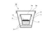
次に、図1に示すような二重ルツボ10に、得られた仮焼粉末11を装入して還元雰囲気中での熱処理を行った。この熱処理は、先ず仮焼粉末11をカーボンシート3を敷いたアルミナ製皿4の上に置き、それを底部に黒鉛粉末5を敷いたアルミナルツボ1に入れて蓋1aをした。その後、アルミナルツボ1よりも一回り大きなアルミナルツボ2の底に黒鉛粉末5を敷き、その黒鉛粉末5の上にアルミナルツボ1を入れて、アルミナルツボ2の蓋2aを閉めた。これを小型ボックス炉(KBF314N1型)の炉内に入れて、還元雰囲気中で1400℃×2時間の熱処理を行った。
この熱処理に用いたルツボの内部構造を図1に示す。このような二重ルツボ法を用いることで簡便にCO−CO2還元雰囲気下で熱処理をすることができる。
Next, the obtained calcined
The internal structure of the crucible used for this heat treatment is shown in FIG. By using such a double crucible method, heat treatment can be easily performed in a CO—CO 2 reducing atmosphere.
熱処理した試料は、若干焼結が見られたため解砕を行って蛍光体粉末を得た。得られた蛍光体は図2の2−1に示すような、ICDD(29−0214)に記載されているBaZrSi3O9の回折パターンを示した。PLスペクトルを図3に、各励起波長(300nm、380nm、400nm、420nm)での相対発光強度を表1に示す。 Since the sintered sample was slightly sintered, it was crushed to obtain a phosphor powder. The obtained phosphor showed the diffraction pattern of BaZrSi 3 O 9 described in ICDD (29-0214) as shown in FIG. FIG. 3 shows the PL spectrum, and Table 1 shows the relative emission intensity at each excitation wavelength (300 nm, 380 nm, 400 nm, 420 nm).
Ba:Zr:Si:Euを0.98:1.0:3.3:0.02となるように原料水溶液をピペットでビーカーに注入した以外は実施例1と同様の操作を行って蛍光体粉末を作製した。
そのXRDパターンを図2の2−2に示す。
得られた蛍光体はICDD(29−0214)に記載されているBaZrSi3O9の回折パターン(図2の2−0参照)を示し、さらに2θ=22度付近に、微弱なSiO2(クリストバライト)相が確認された。
PLスペクトルを図3に、各励起波長での相対発光強度を表1に併せて示す。
A phosphor was obtained by performing the same operation as in Example 1 except that the aqueous raw material solution was pipetted into a beaker so that Ba: Zr: Si: Eu was 0.98: 1.0: 3.3: 0.02. A powder was prepared.
The XRD pattern is shown in FIG.
The obtained phosphor shows a diffraction pattern of BaZrSi 3 O 9 (see 2-0 in FIG. 2) described in ICDD (29-0214). Further, in the vicinity of 2θ = 22 degrees, weak SiO 2 (cristobalite) is obtained. ) Phase confirmed.
FIG. 3 shows the PL spectrum, and Table 1 shows the relative emission intensity at each excitation wavelength.
Ba:Zr:Si:Euを0.98:1.0:4.5:0.02となるように原料水溶液をピペットでビーカーに注入した以外は実施例1と同様の操作を行って蛍光体粉末を作製した。
XRDパターンを図2の2−3に示す。得られた蛍光体はICDD(29−0214)に記載されているBaZrSi3O9の回折パターンを示し、さらに2θ=22°付近にSiO2(クリストバライト)相が確認された。
PLスペクトルを図3に、各励起波長での相対発光強度を表1に併せて示す。
The phosphor was obtained by performing the same operation as in Example 1 except that Ba: Zr: Si: Eu was 0.98: 1.0: 4.5: 0.02 and the raw material aqueous solution was pipetted into the beaker. A powder was prepared.
The XRD pattern is shown in FIG. The obtained phosphor showed a diffraction pattern of BaZrSi 3 O 9 described in ICDD (29-0214), and a SiO 2 (cristobalite) phase was confirmed around 2θ = 22 °.
FIG. 3 shows the PL spectrum, and Table 1 shows the relative emission intensity at each excitation wavelength.
Ba:Zr:Si:Euを0.98:1.0:6.0:0.02となるように原料水溶液をピペットでビーカーに注入した以外は実施例1と同様の操作を行って蛍光体粉末を作製した。
そのXRDパターンを図2の2−4に示す。得られた蛍光体はICDD(29−0214)に記載されているBaZrSi3O9の回折パターンを示し、さらに2θ=22°付近にSiO2(クリストバライト)相が確認された。
PLスペクトルを図3に、各励起波長での相対発光強度を表1に併せて示す。
The phosphor was obtained by performing the same operation as in Example 1 except that Ba: Zr: Si: Eu was 0.98: 1.0: 6.0: 0.02 and the aqueous raw material solution was pipetted into the beaker. A powder was prepared.
The XRD pattern is shown in 2-4 of FIG. The obtained phosphor showed a diffraction pattern of BaZrSi 3 O 9 described in ICDD (29-0214), and a SiO 2 (cristobalite) phase was confirmed around 2θ = 22 °.
FIG. 3 shows the PL spectrum, and Table 1 shows the relative emission intensity at each excitation wavelength.
実施例2で作製した蛍光体粉末を、黒鉛二重ルツボで1400℃×2時間で再度還元雰囲気中の熱処理を行った。
PLスペクトルを図3に、各励起波長での相対発光強度を表1に併せて示す。
The phosphor powder produced in Example 2 was again heat-treated in a reducing atmosphere at 1400 ° C. for 2 hours with a graphite double crucible.
FIG. 3 shows the PL spectrum, and Table 1 shows the relative emission intensity at each excitation wavelength.
仕込みのBa:Zr:Si:Euを0.96:1.0:3.3:0.04とした以外は、実施例5と同様の操作を行って蛍光体粉末を作製した。
PLスペクトルを図3に、各励起波長での相対発光強度を表1に併せて示す。
A phosphor powder was produced in the same manner as in Example 5 except that the charged Ba: Zr: Si: Eu was changed to 0.96: 1.0: 3.3: 0.04.
FIG. 3 shows the PL spectrum, and Table 1 shows the relative emission intensity at each excitation wavelength.
実施例1で得られた蛍光体粉末を、アルミナルツボに入れ、小型ボックス炉(KBF314N1型)の炉内に入れて、大気雰囲気中で500℃×1時間の熱処理を行って、蛍光体粉末を得た。得られた蛍光体粉末の蛍光特性を評価し、図5、表1にまとめて示した。 The phosphor powder obtained in Example 1 is placed in an alumina crucible, placed in a small box furnace (KBF314N1 type) furnace, and subjected to heat treatment at 500 ° C. for 1 hour in an air atmosphere to obtain the phosphor powder. Obtained. The fluorescent characteristics of the obtained phosphor powder were evaluated and are shown in FIG.
実施例1で得られた蛍光体粉末を、アルミナルツボに入れ、小型ボックス炉(KBF314N1型)の炉内に入れて、大気雰囲気中で1000℃×1時間の熱処理を行って、蛍光体粉末を得た。得られた蛍光体粉末の蛍光特性を評価し、図5、表1にまとめて示した。 The phosphor powder obtained in Example 1 is put in an alumina crucible, placed in a small box furnace (KBF314N1 type) furnace, and heat-treated at 1000 ° C. for 1 hour in an air atmosphere to obtain the phosphor powder. Obtained. The fluorescent characteristics of the obtained phosphor powder were evaluated and are shown in FIG.
実施例1で得られた蛍光体粉末を、アルミナルツボに入れ、小型ボックス炉(KBF314N1型)の炉内に入れて、大気雰囲気中で1200℃×1時間の熱処理を行って、蛍光体粉末を得た。得られた蛍光体粉末の蛍光特性を評価し図5、表1にまとめて示した。 The phosphor powder obtained in Example 1 is placed in an alumina crucible, placed in a small box furnace (KBF314N1 type) furnace, and subjected to heat treatment at 1200 ° C. for 1 hour in an air atmosphere to obtain the phosphor powder. Obtained. The fluorescent characteristics of the obtained phosphor powder were evaluated and are shown in FIG.
実施例1と同じ条件で仮焼粉末を作製し、これを卓上高温管状炉(山田電気製、TSR−630)に入れて、水素ガスを4%含むアルゴンガスを100ml/分の流量で流しながら1400℃×2時間の還元雰囲気の熱処理を行って、蛍光体粉末を得た。その後、得られた蛍光体粉末を、アルミナルツボに入れ、小型ボックス炉(KBF314N1型)の炉内に入れて、大気雰囲気中で1200℃×1時間の熱処理を行って、蛍光体粉末を得た。得られた蛍光体粉末の蛍光特性を評価し、図5、表1にまとめて示した。 A calcined powder was prepared under the same conditions as in Example 1, and this was placed in a tabletop high-temperature tubular furnace (manufactured by Yamada Denki, TSR-630), and argon gas containing 4% of hydrogen gas was allowed to flow at a flow rate of 100 ml / min. Heat treatment was performed in a reducing atmosphere at 1400 ° C. for 2 hours to obtain phosphor powder. Thereafter, the obtained phosphor powder was put in an alumina crucible, placed in a small box furnace (KBF314N1 type) furnace, and subjected to heat treatment at 1200 ° C. for 1 hour in an air atmosphere to obtain a phosphor powder. . The fluorescent characteristics of the obtained phosphor powder were evaluated and are shown in FIG.
(比較例1)
BaCO3(関東化学株式会社製、純度3N)、ZrO2(和光純薬工業株式会社製)、SiO2(和光純薬工業株式会社製)、Eu2O3(フルウチ化学株式会社製)の各原料を、Ba:Zr:Si:Euのモル比が0.98:1.0:3.0:0.02となるように秤量し、メノウ乳鉢で20分混合した。
これを実施例1同様の黒鉛二重ルツボで1400℃×2時間の熱処理を行った。得られた蛍光体は、実施例1同様にICDD(29−0214)に記載されているBaZrSi3O9の回折パターンを示したが、PLスペクトルを図3に、各励起波長での相対発光強度を表1に併せて示すが、極めて低い発光強度であった。
(Comparative Example 1)
BaCO 3 (manufactured by Kanto Chemical Co., Inc., purity 3N), ZrO 2 (manufactured by Wako Pure Chemical Industries, Ltd.), SiO 2 (manufactured by Wako Pure Chemical Industries, Ltd.), Eu 2 O 3 (manufactured by Furuuchi Chemical Co., Ltd.) The raw materials were weighed so that the molar ratio of Ba: Zr: Si: Eu was 0.98: 1.0: 3.0: 0.02, and mixed in an agate mortar for 20 minutes.
This was heat-treated at 1400 ° C. for 2 hours using the same graphite double crucible as in Example 1. The obtained phosphor showed the diffraction pattern of BaZrSi 3 O 9 described in ICDD (29-0214) as in Example 1. The PL spectrum is shown in FIG. 3, and the relative emission intensity at each excitation wavelength is shown. Are shown together in Table 1, and the emission intensity was extremely low.
(比較例2)
熱処理温度を450℃とした以外は、実施例7と同じ条件で大気中熱処理を行い、蛍光体粉末を得た。実施例1の蛍光特性と変わらず、同程度の発光特性を示し、大気中熱処理による特性の向上が見られなかった。
(Comparative Example 2)
Except that the heat treatment temperature was 450 ° C., heat treatment was performed in the air under the same conditions as in Example 7 to obtain a phosphor powder. It was the same as the fluorescence characteristic of Example 1 and showed similar light emission characteristics, and no improvement in characteristics due to heat treatment in the atmosphere was observed.
(比較例3)
実施例1で得られた蛍光体粉末の大気中熱処理温度を1550℃とした以外は実施例7と同じ条件で大気中熱処理を行い、蛍光体粉末を得た。蛍光体が溶融し、分解してしまい、発光しなかった。
(Comparative Example 3)
The phosphor powder obtained in Example 1 was heat-treated in the atmosphere under the same conditions as in Example 7 except that the heat treatment temperature in the atmosphere was changed to 1550 ° C. to obtain a phosphor powder. The phosphor melted and decomposed and did not emit light.
[蛍光体粉末の評価結果]
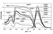
図3、表1から明らかなように、本発明による蛍光体は、いずれも近紫外LEDの発光波長である400nm前後でフラットな励起スペクトルを示していることが分かる。特に本発明の製造方法を用いた実施例1〜6は、従来法である固相法による比較例1よりも著しく大きな発光強度を示す。SiO2を化学量論よりリッチにした実施例2、3、4は、実施例1よりも発光強度が大きい。また、再還元焼成を行った実施例5および6の蛍光体は発光強度が特に著しく向上している。図4の励起スペクトル形状の比較からも本発明によるBaZrSi3O9:Eu蛍光体は、公知の励起スペクトル(特許文献1の例2)とは異なる形状を有しているのが明白である。
[Evaluation results of phosphor powder]
As is apparent from FIG. 3 and Table 1, it can be seen that the phosphors according to the present invention all exhibit a flat excitation spectrum around 400 nm, which is the emission wavelength of the near-ultraviolet LED. In particular, Examples 1 to 6 using the production method of the present invention show significantly higher emission intensity than Comparative Example 1 by the solid phase method which is a conventional method. In Examples 2, 3, and 4 in which SiO 2 is made richer than the stoichiometry, the emission intensity is higher than that in Example 1. In addition, the phosphors of Examples 5 and 6 that have been subjected to re-reduction firing have particularly improved emission intensity. From comparison of the excitation spectrum shapes shown in FIG. 4, it is apparent that the BaZrSi 3 O 9 : Eu phosphor according to the present invention has a shape different from that of the known excitation spectrum (Example 2 of Patent Document 1).
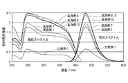
図5、表1から明らかなように、還元処理後に行う酸素雰囲気下での熱処理の効果については実施例7から実施例10、比較例2、3に示すように、本発明の範囲内、即ち500から1500℃の温度範囲において大気(空気)のような酸素雰囲気下で熱処理を行った実施例7から実施例10では、この熱処理を施さなかった実施例1と比較して、励起特性、発光特性共に向上していることがわかる。特に1000℃から1200℃の熱処理温度で処理した実施例8、9、10では著しい向上が見られる。
一方、この熱処理の温度が450℃と低かった比較例2では、励起特性、発光特性共に実施例1より向上が見られず熱処理の効果が見られなかった。また、温度が高すぎた比較例3では試料が作製できなかった。
As apparent from FIG. 5 and Table 1, as shown in Examples 7 to 10 and Comparative Examples 2 and 3, the effects of the heat treatment in the oxygen atmosphere performed after the reduction treatment are within the scope of the present invention, that is, In Example 7 to Example 10 in which heat treatment was performed in an oxygen atmosphere such as air (air) in a temperature range of 500 to 1500 ° C., excitation characteristics and light emission were compared with Example 1 in which this heat treatment was not performed. It can be seen that both characteristics are improved. In particular, in Examples 8, 9, and 10 treated at a heat treatment temperature of 1000 ° C. to 1200 ° C., significant improvement is observed.
On the other hand, in Comparative Example 2 in which the temperature of this heat treatment was as low as 450 ° C., neither the excitation characteristics nor the light emission characteristics were improved as compared with Example 1, and the effect of the heat treatment was not seen. In Comparative Example 3 where the temperature was too high, a sample could not be produced.
以上、説明したように、本発明によるBaZrSi3O9:Eu蛍光体は、近紫外LEDの発光波長である400nm前後での発光強度が大きく、励起波長の変化に対する発光強度の変化が小さい。そのため、本発明のシリケート蛍光体は近紫外LED励起用の青色蛍光体として非常に好適である。 As described above, the BaZrSi 3 O 9 : Eu phosphor according to the present invention has a large emission intensity around 400 nm, which is the emission wavelength of a near-ultraviolet LED, and a small change in emission intensity with respect to a change in excitation wavelength. Therefore, the silicate phosphor of the present invention is very suitable as a blue phosphor for near-ultraviolet LED excitation.
1 アルミナルツボ(内側)
1a アルミナルツボ1の蓋
2 アルミナルツボ(外側)
2a アルミナルツボ2の蓋
3 カーボンシート
4 アルミナ製皿
5 黒鉛粉末
10 二重ルツボ
11 仮焼粉末
1 Alumina crucible (inside)
Claims (5)
粉末X線回折パターンにおいて、BaZrSi3O9の回折パターンを有し、
励起波長400nmにおける発光強度が励起波長300nmにおける発光強度の40%以上、
励起波長380nm〜420nmの範囲において、下記(1)式で表される発光強度変化率が30%以下、
であることを特徴とする。
In the powder X-ray diffraction pattern, it has a diffraction pattern of BaZrSi 3 O 9
The emission intensity at an excitation wavelength of 400 nm is 40% or more of the emission intensity at an excitation wavelength of 300 nm,
In the excitation wavelength range of 380 nm to 420 nm, the emission intensity change rate represented by the following formula (1) is 30% or less,
It is characterized by being.
粉末X線回折パターンにおいて、BaZrSi3O9の回折パターンを有し、かつ、ブラッグ角度(2θ)の22°付近にSiO2(クリストバライト)由来のピークを有し、
励起波長400nmにおける発光強度が励起波長300nmにおける発光強度の40%以上で、
励起波長380nm〜420nmの範囲において、前記(1)式で表される発光強度変化率が30%以下
であることを特徴とする。 A silicate phosphor represented by a composition formula of Ba 1-x Eu x ZrSi y O 3 + 2y (where 0.001 ≦ x ≦ 0.5, 3 <y ≦ 6),
In the powder X-ray diffraction pattern, it has a diffraction pattern of BaZrSi 3 O 9 and has a peak derived from SiO 2 (cristobalite) around 22 ° of the Bragg angle (2θ),
The emission intensity at an excitation wavelength of 400 nm is 40% or more of the emission intensity at an excitation wavelength of 300 nm,
In the excitation wavelength range of 380 nm to 420 nm, the emission intensity change rate represented by the formula (1) is 30% or less.
下記の工程1から工程3を含むことを特徴とする。
工程1:構成成分の中の金属成分であるBa、Zr、Eu、Si元素を水溶液として混合し、さらにオキシカルボン酸を加えた混合液を加熱して前記混合液をゲル化し、次いで乾燥してゲル体を形成する工程。
工程2:工程1で作製したゲル体を、大気中で焼成することによりゲル体に含まれる有機物を除去して、構成成分が均一に分布した前駆体を作製する工程。
工程3:工程2で作製した前駆体を、還元雰囲気中で熱処理することにより、BaZrSi3O9結晶相を得ると同時に、EuをBaサイトに還元ドープして高輝度に発光するシリケート蛍光体粉末を形成する工程。 A method for producing a silicate phosphor represented by a composition formula of Ba 1-x Eu x ZrSi y O 3 + 2y (where 0.001 ≦ x ≦ 0.5, 2.5 ≦ y ≦ 6),
The following steps 1 to 3 are included.
Step 1: Ba, Zr, Eu, and Si elements, which are metal components in the constituent components, are mixed as an aqueous solution, and the mixed solution to which oxycarboxylic acid is added is heated to gel the mixed solution, and then dried. A step of forming a gel body.
Step 2: The step of producing a precursor in which constituent components are uniformly distributed by removing the organic matter contained in the gel by baking the gel produced in Step 1 in the air.
Step 3: A silicate phosphor powder that obtains a BaZrSi 3 O 9 crystal phase by heat-treating the precursor prepared in Step 2 in a reducing atmosphere, and simultaneously emits Eu at a Ba site by reduction doping. Forming.
Priority Applications (1)
| Application Number | Priority Date | Filing Date | Title |
|---|---|---|---|
| JP2011119130A JP5484397B2 (en) | 2010-12-24 | 2011-05-27 | Silicate phosphor and method for producing the same |
Applications Claiming Priority (3)
| Application Number | Priority Date | Filing Date | Title |
|---|---|---|---|
| JP2010288873 | 2010-12-24 | ||
| JP2010288873 | 2010-12-24 | ||
| JP2011119130A JP5484397B2 (en) | 2010-12-24 | 2011-05-27 | Silicate phosphor and method for producing the same |
Publications (3)
| Publication Number | Publication Date |
|---|---|
| JP2012144689A true JP2012144689A (en) | 2012-08-02 |
| JP2012144689A5 JP2012144689A5 (en) | 2013-09-19 |
| JP5484397B2 JP5484397B2 (en) | 2014-05-07 |
Family
ID=46788586
Family Applications (1)
| Application Number | Title | Priority Date | Filing Date |
|---|---|---|---|
| JP2011119130A Active JP5484397B2 (en) | 2010-12-24 | 2011-05-27 | Silicate phosphor and method for producing the same |
Country Status (1)
| Country | Link |
|---|---|
| JP (1) | JP5484397B2 (en) |
Cited By (2)
| Publication number | Priority date | Publication date | Assignee | Title |
|---|---|---|---|---|
| JP5512871B1 (en) * | 2013-05-20 | 2014-06-04 | 住友金属鉱山株式会社 | Blue light emitting silicate phosphor and method for producing the same |
| JP2020097639A (en) * | 2018-12-17 | 2020-06-25 | 浜松ホトニクス株式会社 | Ultraviolet light emitting phosphor, method for producing the same, and ultraviolet excitation light source |
Citations (7)
| Publication number | Priority date | Publication date | Assignee | Title |
|---|---|---|---|---|
| JP2004224830A (en) * | 2003-01-20 | 2004-08-12 | Japan Science & Technology Agency | Light-emitting body and method of manufacturing the same |
| JP2006002043A (en) * | 2004-06-17 | 2006-01-05 | Daiden Co Ltd | Fluorescent substance to be excited by vacuum ultraviolet rays, method for producing the same, and vacuum ultraviolet ray-excited light-emitting element |
| JP2008063550A (en) * | 2006-08-10 | 2008-03-21 | Sumitomo Chemical Co Ltd | Phosphor |
| JP2010189583A (en) * | 2009-02-19 | 2010-09-02 | Sumitomo Metal Mining Co Ltd | Method for producing oxide phosphor |
| JP2011032416A (en) * | 2009-08-04 | 2011-02-17 | Sumitomo Metal Mining Co Ltd | Phosphor, and method for producing the same |
| WO2011148910A1 (en) * | 2010-05-25 | 2011-12-01 | 住友金属鉱山株式会社 | PROCESS FOR PRODUCTION OF Eu-ACTIVATED ALKALINE EARTH METAL SILICATE PHOSPHOR |
| JP2012092233A (en) * | 2010-10-27 | 2012-05-17 | Sumitomo Metal Mining Co Ltd | Oxynitride phosphor and method for producing the same |
-
2011
- 2011-05-27 JP JP2011119130A patent/JP5484397B2/en active Active
Patent Citations (7)
| Publication number | Priority date | Publication date | Assignee | Title |
|---|---|---|---|---|
| JP2004224830A (en) * | 2003-01-20 | 2004-08-12 | Japan Science & Technology Agency | Light-emitting body and method of manufacturing the same |
| JP2006002043A (en) * | 2004-06-17 | 2006-01-05 | Daiden Co Ltd | Fluorescent substance to be excited by vacuum ultraviolet rays, method for producing the same, and vacuum ultraviolet ray-excited light-emitting element |
| JP2008063550A (en) * | 2006-08-10 | 2008-03-21 | Sumitomo Chemical Co Ltd | Phosphor |
| JP2010189583A (en) * | 2009-02-19 | 2010-09-02 | Sumitomo Metal Mining Co Ltd | Method for producing oxide phosphor |
| JP2011032416A (en) * | 2009-08-04 | 2011-02-17 | Sumitomo Metal Mining Co Ltd | Phosphor, and method for producing the same |
| WO2011148910A1 (en) * | 2010-05-25 | 2011-12-01 | 住友金属鉱山株式会社 | PROCESS FOR PRODUCTION OF Eu-ACTIVATED ALKALINE EARTH METAL SILICATE PHOSPHOR |
| JP2012092233A (en) * | 2010-10-27 | 2012-05-17 | Sumitomo Metal Mining Co Ltd | Oxynitride phosphor and method for producing the same |
Cited By (2)
| Publication number | Priority date | Publication date | Assignee | Title |
|---|---|---|---|---|
| JP5512871B1 (en) * | 2013-05-20 | 2014-06-04 | 住友金属鉱山株式会社 | Blue light emitting silicate phosphor and method for producing the same |
| JP2020097639A (en) * | 2018-12-17 | 2020-06-25 | 浜松ホトニクス株式会社 | Ultraviolet light emitting phosphor, method for producing the same, and ultraviolet excitation light source |
Also Published As
| Publication number | Publication date |
|---|---|
| JP5484397B2 (en) | 2014-05-07 |
Similar Documents
| Publication | Publication Date | Title |
|---|---|---|
| CN102378800B (en) | Aluminum oxide phosphor and method for producing same | |
| JP5110336B2 (en) | Phosphor particles | |
| JP6610739B2 (en) | Oxynitride phosphor powder and light emitting device using the same | |
| JP5578739B2 (en) | Alkaline earth metal silicate phosphor and method for producing the same | |
| TWI544059B (en) | Manufacturing method of yttrium cerium aluminum garnet phosphor | |
| US9758720B2 (en) | Oxynitride phosphor powder, silicon nitride powder for production of oxynitride phosphor powder, and production method of oxynitride phosphor powder | |
| KR101854114B1 (en) | Metal fluoride-based red phosphors and light emitting device containing the same | |
| KR101414948B1 (en) | PROCESS FOR PRODUCTION OF Eu-ACTIVATED ALKALINE EARTH METAL SILICATE PHOSPHOR | |
| JP5484397B2 (en) | Silicate phosphor and method for producing the same | |
| WO2014006755A1 (en) | Silicate phosphor and process for manufacturing same | |
| CN105199725A (en) | Alkali-metal-ion-reinforced red light type fluorescent powder formed by adulterating titanate in rare earth and preparation method | |
| KR100280369B1 (en) | Manufacturing method of green light emitting phosphor | |
| JP2012144689A5 (en) | ||
| JP5512871B1 (en) | Blue light emitting silicate phosphor and method for producing the same | |
| CN107573934B (en) | A kind of preparation method of Mn4+-doped potassium fluorogermanate red phosphor | |
| KR101330862B1 (en) | Particle Size Control of YAG Type Phosphor by the Liquid-State-Reaction Method Using Urea, and Manufacturing Method thereof | |
| CN107760303B (en) | Method for preparing YAG-Ce fluorescent powder in low-temperature solid phase manner | |
| JP5444271B2 (en) | Method for producing alkaline earth metal silicate phosphor | |
| JP5420015B2 (en) | Sulfide phosphor and method for producing the same | |
| JP2013151617A (en) | Method of manufacturing alkaline earth metal silicate phosphor and alkaline earth metal silicate phosphor | |
| JP2013129765A (en) | Method for production of alkaline earth metal silicate phosphor, and the alkaline earth metal silicate phosphor | |
| JP2012177031A (en) | Yellow phosphor and method for producing the same |
Legal Events
| Date | Code | Title | Description |
|---|---|---|---|
| A521 | Request for written amendment filed |
Free format text: JAPANESE INTERMEDIATE CODE: A523 Effective date: 20120712 |
|
| A521 | Request for written amendment filed |
Free format text: JAPANESE INTERMEDIATE CODE: A523 Effective date: 20130709 |
|
| A621 | Written request for application examination |
Free format text: JAPANESE INTERMEDIATE CODE: A621 Effective date: 20130709 |
|
| A871 | Explanation of circumstances concerning accelerated examination |
Free format text: JAPANESE INTERMEDIATE CODE: A871 Effective date: 20130709 |
|
| A521 | Request for written amendment filed |
Free format text: JAPANESE INTERMEDIATE CODE: A821 Effective date: 20130708 |
|
| A975 | Report on accelerated examination |
Free format text: JAPANESE INTERMEDIATE CODE: A971005 Effective date: 20130912 |
|
| A131 | Notification of reasons for refusal |
Free format text: JAPANESE INTERMEDIATE CODE: A131 Effective date: 20130918 |
|
| A521 | Request for written amendment filed |
Free format text: JAPANESE INTERMEDIATE CODE: A523 Effective date: 20131115 |
|
| A131 | Notification of reasons for refusal |
Free format text: JAPANESE INTERMEDIATE CODE: A131 Effective date: 20131225 |
|
| A521 | Request for written amendment filed |
Free format text: JAPANESE INTERMEDIATE CODE: A523 Effective date: 20140129 |
|
| TRDD | Decision of grant or rejection written | ||
| A01 | Written decision to grant a patent or to grant a registration (utility model) |
Free format text: JAPANESE INTERMEDIATE CODE: A01 Effective date: 20140214 |
|
| A61 | First payment of annual fees (during grant procedure) |
Free format text: JAPANESE INTERMEDIATE CODE: A61 Effective date: 20140218 |
|
| R150 | Certificate of patent or registration of utility model |
Ref document number: 5484397 Country of ref document: JP Free format text: JAPANESE INTERMEDIATE CODE: R150 |
|
| R250 | Receipt of annual fees |
Free format text: JAPANESE INTERMEDIATE CODE: R250 |
|
| R250 | Receipt of annual fees |
Free format text: JAPANESE INTERMEDIATE CODE: R250 |
|
| R250 | Receipt of annual fees |
Free format text: JAPANESE INTERMEDIATE CODE: R250 |
|
| R250 | Receipt of annual fees |
Free format text: JAPANESE INTERMEDIATE CODE: R250 |
|
| R250 | Receipt of annual fees |
Free format text: JAPANESE INTERMEDIATE CODE: R250 |
|
| R250 | Receipt of annual fees |
Free format text: JAPANESE INTERMEDIATE CODE: R250 |
|
| R250 | Receipt of annual fees |
Free format text: JAPANESE INTERMEDIATE CODE: R250 |
|
| R250 | Receipt of annual fees |
Free format text: JAPANESE INTERMEDIATE CODE: R250 |
|
| R250 | Receipt of annual fees |
Free format text: JAPANESE INTERMEDIATE CODE: R250 |
|
| R250 | Receipt of annual fees |
Free format text: JAPANESE INTERMEDIATE CODE: R250 |