JP2012144342A - Tong suspender - Google Patents
Tong suspender Download PDFInfo
- Publication number
- JP2012144342A JP2012144342A JP2011004447A JP2011004447A JP2012144342A JP 2012144342 A JP2012144342 A JP 2012144342A JP 2011004447 A JP2011004447 A JP 2011004447A JP 2011004447 A JP2011004447 A JP 2011004447A JP 2012144342 A JP2012144342 A JP 2012144342A
- Authority
- JP
- Japan
- Prior art keywords
- tong
- workpiece
- tongue
- arm
- lifting device
- Prior art date
- Legal status (The legal status is an assumption and is not a legal conclusion. Google has not performed a legal analysis and makes no representation as to the accuracy of the status listed.)
- Granted
Links
- 230000007246 mechanism Effects 0.000 claims abstract description 26
- 239000000725 suspension Substances 0.000 abstract description 13
- 230000008901 benefit Effects 0.000 abstract description 5
- 230000005540 biological transmission Effects 0.000 description 4
- 230000000694 effects Effects 0.000 description 4
- 238000003780 insertion Methods 0.000 description 3
- 230000037431 insertion Effects 0.000 description 3
- 230000008859 change Effects 0.000 description 2
- 230000001771 impaired effect Effects 0.000 description 2
- 239000000463 material Substances 0.000 description 2
- 238000000034 method Methods 0.000 description 2
- 230000009467 reduction Effects 0.000 description 2
- 230000008878 coupling Effects 0.000 description 1
- 238000010168 coupling process Methods 0.000 description 1
- 238000005859 coupling reaction Methods 0.000 description 1
- 230000003247 decreasing effect Effects 0.000 description 1
- 238000010586 diagram Methods 0.000 description 1
- 229910003460 diamond Inorganic materials 0.000 description 1
- 239000010432 diamond Substances 0.000 description 1
- 238000006073 displacement reaction Methods 0.000 description 1
- 238000005516 engineering process Methods 0.000 description 1
- 230000004044 response Effects 0.000 description 1
Images


Landscapes
- Manipulator (AREA)
- Load-Engaging Elements For Cranes (AREA)
Abstract
Description
本発明は、ワークの自重を利用したリンク機構の回転動作でワークを挟込んで吊持するトング式吊具に係る技術分野に属する。 The present invention belongs to a technical field related to a tong-type lifting device that sandwiches and suspends a workpiece by a rotating operation of a link mechanism that uses the weight of the workpiece.
トング式吊具は、ワークの自重を利用して回転動作される4節回転機構等のリンク機構によってワークを挟込むように構成することで、ワークの挟込みを駆動する挟込駆動部を別個に備えることを不要にして、装置構成の小型化,簡素化が図られている。 The tong-type lifting device is configured such that the workpiece is sandwiched by a link mechanism such as a four-bar rotation mechanism that is rotated by utilizing the weight of the workpiece, so that a clamping drive unit that drives the workpiece is separately provided. Therefore, it is not necessary to prepare for the device configuration, and the device configuration is reduced in size and simplified.
このトング式吊具では、ワークの加工に対応してワークの吊持の姿勢(向き)を変更する必要がある場合、吊持を解除して床面等で姿勢を変更した後に再度吊持するという煩雑な作業が必要になる。このため、トング式吊具について、ワークを吊持したまま姿勢を変更できるようにする技術の開発が要望されている。 In this tong type lifting tool, when it is necessary to change the posture (orientation) of the workpiece in response to the processing of the workpiece, the suspension is released and the posture is changed on the floor surface and then suspended again. This is a complicated task. For this reason, there is a demand for the development of a technology that enables the posture of the tongue-type lifting device to be changed while the workpiece is suspended.
従来、トング式吊具についてワークを吊持したまま姿勢を変更できるようにする技術としては、例えば、特許文献1に記載のものが知られている。 Conventionally, for example, a technique described in Patent Document 1 is known as a technique for changing the posture of a tongue-type hanging tool while holding a workpiece.
特許文献1には、ワークの自重を利用したリンク機構の回転動作でワークを挟込んで吊持するものであって、相対してワークを挟込む挟込支持部がリンク機構を構成するトングアームの下部にそれぞれ回転可能に取付けられ、一方のトングアームに一方の挟込支持部を回転駆動するギア減速部,モータからなる回転駆動部が取付けられたトング式吊具が記載されている。 Patent Document 1 discloses a tong arm in which a workpiece is sandwiched and suspended by a rotation operation of a link mechanism that uses the weight of the workpiece, and a sandwiching support portion that sandwiches the workpiece is a link mechanism. A tong-type lifting device is described, which is rotatably attached to the lower part of each of the gears, and has a gear reduction part for rotationally driving one clamping support part and a rotational driving part comprising a motor attached to one tong arm.
特許文献1に係るトング式吊具は、回転駆動部で一方の挟込支持部を回転駆動させることで、両挟込支持部を通る軸中心線を中心としてワークを回転させて、トングアームの下部に吊持されているワークの姿勢を変更することができるようにしたものである。 The tong-type suspension device according to Patent Document 1 rotates the workpiece around the axis center line passing through both sandwiching support portions by rotating and driving one of the sandwiching support portions by the rotation drive unit, The posture of the work suspended in the lower part can be changed.
特許文献1に係るトング式吊具では、挟込支持部を回転駆動する回転駆動部がギア減速部,モータからなり大型であるため、装置構成が小型,簡素であるという利点が損なわれてしまうという問題点がある。また、挟込支持部を回転駆動する大型(大重量)の回転駆動部が一方のトングアームに取付けられ、ワークの挟込みの両側の重量バランスが崩れてしまっているため、ワークの吊持作業の安全性が確保されにくくなっているという問題点がある。 In the tong-type lifting device according to Patent Document 1, the rotational drive unit that rotationally drives the sandwiching support unit is a large size composed of a gear reduction unit and a motor, so that the advantage that the device configuration is small and simple is lost. There is a problem. In addition, a large (heavy) rotary drive unit that rotates the clamping support unit is attached to one of the tong arms, and the weight balance on both sides of the workpiece clamping is broken, so the workpiece is suspended. There is a problem that it is difficult to ensure safety.
本発明は、このような問題点を考慮してなされたもので、装置構成が小型,簡素であるという利点が損なわれることなく、しかもワークの吊持作業の安全性が確保されるトング式吊具を提供することを課題とする。 The present invention has been made in consideration of such problems, and the tong-type suspension is ensured without sacrificing the advantage that the device configuration is small and simple and ensuring the safety of the work suspension work. It is an object to provide tools.
前述の課題を解決するため、本発明に係るトング式吊具は、特許請求の範囲の各請求項に記載の手段を採用する。 In order to solve the above-described problems, the tongue-type lifting device according to the present invention employs means described in each of the claims.
即ち、請求項1では、ワークの自重を利用したリンク機構の回転動作でワークを挟込んで吊持するものであって、相対してワークを挟込む挟込支持部がリンク機構を構成するトングアームの下部にそれぞれ回転可能に取付けられ、一方のトングアームに一方の挟込支持部を回転駆動する回転駆動部が取付けられたトング式吊具において、回転駆動部は手動の操作ハンドルで回転操作されるウオームギア,ウオームホイールのギア噛合構造からなることを特徴とする。 That is, according to the first aspect of the present invention, the workpiece is sandwiched and suspended by the rotation operation of the link mechanism using the weight of the workpiece, and the tong support portion that sandwiches the workpiece relative to the link mechanism constitutes the link mechanism. In the tong-type lifting device, which is rotatably attached to the lower part of the arm, and a rotary drive unit is attached to one of the tong arms, and the rotary drive unit is rotated by a manual operation handle. It is characterized by comprising a gear meshing structure of a worm gear and a worm wheel.
この手段では、回転駆動部が手動で回転操作されるコンパクトな機械要素で構成されることで、回転駆動部の大型化,複雑化,重量増加が避けられる。 In this means, the rotation drive unit is composed of a compact machine element that is manually operated to rotate, thereby avoiding an increase in size, complexity, and weight of the rotation drive unit.
また、請求項2では、請求項1のトング式吊具において、挟込支持部は球面軸受を介してトングアームに変位可能に支持されていることを特徴とする。 According to a second aspect of the present invention, in the tong type lifting tool of the first aspect, the sandwiching support portion is supported by the tongue arm via a spherical bearing so as to be displaceable.
この手段では、挟込支持部が球面軸受を介してトングアームに支持されることで、挟込支持部がワークの被挟込面に対応して変位される。 In this means, the sandwiching support portion is supported by the tongue arm via the spherical bearing, whereby the sandwiching support portion is displaced corresponding to the sandwiched surface of the workpiece.
また、請求項3では、請求項2のトング式吊具において、一方の挟込支持部と回転駆動部とは自在継手を介して非固定的に連結されていることを特徴とする。 According to a third aspect of the present invention, in the tong type lifting device of the second aspect, the one sandwiching support portion and the rotation driving portion are non-fixedly connected via a universal joint.
この手段では、一方の挟込支持部と回転駆動部とが自在継手を介して非固定的に連結されることで、変位した挟込支持部に対する回転駆動部の駆動伝達系が確保される。 In this means, the one clamping support part and the rotation driving part are non-fixedly connected via a universal joint, so that a drive transmission system of the rotation driving part with respect to the displaced clamping support part is secured.
また、請求項4では、請求項1〜3のいずれかのトング式吊具において、他方のトングアームは下部にバランサが取付けられていることを特徴とする。 According to a fourth aspect of the present invention, in the tong-type lifting device of any one of the first to third aspects, a balancer is attached to the lower portion of the other tong arm.
この手段では、他方のトングアームの下部にバランサが取付けられることで、ワークの挟込みの両側の重量バランスの調整が可能になる。 With this means, the balancer is attached to the lower part of the other tong arm, so that the weight balance on both sides of the workpiece can be adjusted.
また、請求項5では、請求項1〜4のいずれかのトング式吊具において、両方のトングアームは相対する挟込支持部の間隔を調整可能な間隔調整機構が設けられていることを特徴とする。 According to a fifth aspect of the present invention, in the tong-type lifting device according to any one of the first to fourth aspects, both of the tong arms are provided with a distance adjusting mechanism capable of adjusting a distance between the opposing sandwiching support portions. And
この手段では、両方のトングアームに間隔調整機構が設けられることで、相対してワークを挟込む挟込支持部の間隔が調整される。 In this means, the interval adjusting mechanism is provided on both of the tong arms, thereby adjusting the interval between the sandwiching support portions that sandwich the workpiece relative to each other.
本発明に係るトング式吊具は、回転駆動部が手動で回転操作されるコンパクトな機械要素で構成されることで、回転駆動部の大型化,複雑化,重量増加が避けられるため、装置構成が小型,簡素であるという利点が損なわれることなく、しかもワークの吊持作業の安全性が確保される効果がある。 The tong-type lifting device according to the present invention is composed of a compact mechanical element in which the rotation drive unit is manually rotated, thereby avoiding an increase in size, complexity and weight of the rotation drive unit. However, the advantages of being small and simple are not impaired, and the safety of the work hanging work is ensured.
さらに、請求項2として、挟込支持部が球面軸受を介してトングアームに支持されることで、挟込支持部がワークの被挟込面に対応して変位されるため、ワークを確実に挟込むことができる効果がある。
Further, as claimed in
さらに、請求項3として、一方の挟込支持部と回転駆動部とが自在継手を介して非固定的に連結されることで、変位した挟込支持部に対する回転駆動部の駆動伝達系が確保されるため、回転駆動部によって挟込支持部を確実に回転駆動することができる効果がある。 Further, as claimed in claim 3, the drive transmission system of the rotational drive unit with respect to the displaced sandwiching support unit is secured by connecting the one sandwiching support unit and the rotational drive unit in a non-fixed manner via a universal joint. Therefore, there is an effect that the sandwiching support portion can be reliably rotated by the rotation drive portion.
さらに、請求項4として、他方のトングアームの下部にバランサが取付けられることで、ワークの挟込みの両側の重量バランスの調整が可能になるため、ワークの吊持作業の安全性がより確実に確保される効果がある。 Furthermore, as claimed in claim 4, since the balancer is attached to the lower portion of the other tong arm, the weight balance on both sides of the workpiece can be adjusted, so that the safety of the workpiece suspension work is more reliably ensured. There is an effect to be secured.
さらに、請求項5として、両方のトングアームに間隔調整機構が設けられることで、相対してワークを挟込む挟込支持部の間隔が調整されるため、大きさの異なるワークの吊持に対応することができ汎用性が高くなる効果がある。
Furthermore, as claimed in
以下、本発明に係るトング式吊具を実施するための形態を図面に基づいて説明する。 EMBODIMENT OF THE INVENTION Hereinafter, the form for implementing the tong type | mold hanging tool which concerns on this invention is demonstrated based on drawing.
この形態では、直方体形のインゴットのようなワークWの吊持に好適なものを示してある。 In this embodiment, a rectangular parallelepiped ingot that is suitable for suspending the workpiece W is shown.
この形態は、図1に示すように、1対の2本の上部リンクアーム1と1対の2本のトングアーム(下部リンクアーム)2とによってワークWの自重を利用して回転動作される4節回転機構からなるリンク機構が構成されている。 In this embodiment, as shown in FIG. 1, a pair of two upper link arms 1 and a pair of two tong arms (lower link arms) 2 are rotated using the weight of the workpiece W. A link mechanism including a four-bar rotation mechanism is configured.
即ち、上部リンクアーム1は、上端部が共通の単一の連結軸3で互いに回動可能に連結され、下端部が連結軸4でトングアーム2の上端部にそれぞれ回動可能に連結されている。トングアーム2は、中途部が交差するように共通の単一の連結軸5で互いに回動可能に連結されている。上部リンクアーム1とトングアーム2の上半部とは、側面形状が平行四角形(菱形)を呈している。
That is, the upper link arm 1 is pivotally connected to each other by a single connecting shaft 3 having a common upper end, and the lower end is pivotally connected to the upper end of the
最上部に位置される連結軸3には、クレーン等から繰出された吊ワイア6が掛けられる吊掛体7が回動可能に連結されている。吊掛体7には、重錘8が固定されている。
A
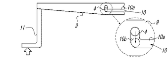
中央部に位置される2つの連結軸4には、上部リンクアーム1とトングアーム2の上半部とが形成する平行四角形を横断して側方へ突出する補助アーム9が連結されている。補助アーム9には、突出端部寄りに一方(側方への突出側)の連結軸4をスライド可能に連結するスライド溝10が刻設され、突出端部に作業員が手を掛けることのできる操作レバー11が取付けられている。スライド溝10は、図6に詳細に示されるように、補助アーム9の長さ方向に長く延びた本体溝10aと、本体溝10aに連通され本体溝10aの補助アーム9の突出端部側の端部から直交して上方へ短く延びたロック溝10bとからなる。
The two connecting shafts 4 positioned at the center are connected to an
最上部に位置される連結軸3と最下部に位置される連結軸5とには、上下方向にスライドされる案内板12が連結されている。案内板12には、下端部にワークWに突当てられる突当板19が固定されている。
A
この形態のトングアーム2には、下部に相対してワークWを挟込む挟込支持部13がそれぞれ取付けられる足形の可動取付部14が間隔調整機構15を介して設けられている。
The
挟込支持部13は、図2,図3に示すように、ワークWに当接される挟込盤13aの回転軸13bに球面体13cが固定され、可動取付部14に回動可能で軸方向が変位可能に取付けられている。
As shown in FIGS. 2 and 3, the
可動取付部14は、下半部14aが連結軸14bを介して上半部14cに回動可能に連結され、下半部14aがバネ材14dで互いに近接するように弾圧され少しの角度θをもって傾斜されるようになっている。下半部14aには、図2,図3に示すように、挟込支持部13の球面体13cに対応して球面軸受を構成する球面座14eが固定されている。
The movable mounting
間隔調整機構15は、可動取付部14の上半部14cの上端部に穿孔されたボルト挿通孔と、トングアーム2の下端部に穿孔され横方向(トングアーム2の相対方向)に並列された複数のボルト挿通孔15aとからなる。この間隔調整機構15は、取付ボルト15bが挿通されるボルト挿通孔15aを選択することによって、可動取付部14の間隔が調整されることになる。
The
この形態の一方の挟込支持部13を回転駆動する回転駆動部16は、図2〜図5に示すように、手動の操作ハンドル16aの回転操作によって噛合されたウオームギア16b,ウオームホイール16cを介して回転駆動されるようになっている。操作ハンドル16aは、可動取付部14の下半部14aに回転可能に支持された操作軸16dの端部に取付けられている。ウオームギア16bは、操作軸16dに同軸に固定されている。ウオームホイール16cは、可動取付部14の下半部14aに回転可能に支持され操作軸16dに直交する駆動軸16eに同軸に固定されている。
As shown in FIGS. 2 to 5, the
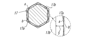
回転駆動部16の駆動軸16eは、自在継手17を介して挟込支持部13の回転軸13bに連結されている。自在継手17は、挟込支持部13の回転軸13bに堀込まれた6角穴17aと、回転駆動部16の駆動軸16eに加工された6角ヘッド17bとからなる。この自在継手17は、図4,図5に詳細に示されるように、6角穴17aよりも6角ヘッド17bが小径に設定されて挟込支持部13の軸方向の変位を許容するスペースSが形成されるとともに、6角穴17aの内接円aよりも6角ヘッド17bの外接円bの方が大きく設定されて駆動伝達が可能になっている。
The
また、回転駆動部16が設けられていない他方の挟込支持部13が支持されている可動取付部14の下半部14aには、バランサ18が取付けられている。このバランサ18は、複数枚のリング板が同軸に積層されていて任意の個数に増減させることができるようになっている。
A
この形態を使用するには、図7に示すように、ワークWのX,Yの中心だしをして、案内板12をスライド降下させて突当板19をワークWに突当てる。このとき、連結軸4がスライド溝10のロック溝10に係止され、上部リンクアーム1とトングアーム2の上半部とが形成する平行四角形が上下に圧縮された状態になっている。なお、ワークWの大きさに対応して間隔調整機構15を調整することになる。また、ワークWの重量変位に対応してバランサ18の個数を調整することになる。
In order to use this configuration, as shown in FIG. 7, the X and Y centers of the workpiece W are centered, the
そして、図6に示すように、操作レバー11を操作して連結軸4をスライド溝10のロック溝10から本体溝10aに移動させる。この結果、トングアーム2,挟込支持部13,可動取付部14,間隔調整機構15,回転駆動部16等の自重によって、上部リンクアーム1とトングアーム2の上半部とが形成する平行四角形が突当板19を支点として正確に上下に拡開され、挟込支持部13がワークWを挟込むことになる。このとき、挟込支持部13の球面体13cと可動取付部14の球面座14eとの球面軸受と、可動取付部14の上半部14cに対する下半部14aの回動とによって、ワークWの被挟込面に精度がなくても確実に挟込むことができる。
Then, as shown in FIG. 6, the
この後、図8に示すように、吊ワイア6を引上げることによって、リンク機構の回転動作でワークWが強固に挟込まれて吊持されることになる。この後、左右の重量バランスが不良である場合には、バランサ18の個数を調整する。
Thereafter, as shown in FIG. 8, by lifting the
吊持されたワークWの姿勢を変更するには、図1に示すように、案内板12をスライド上昇させて突当板19をワークWから離し、ワークWを吊持したまま回転駆動部16を手動で駆動操作することになる。
In order to change the posture of the suspended workpiece W, as shown in FIG. 1, the
即ち、回転駆動部16の操作ハンドル16aを回転操作すると、操作軸16d,ウオームギア16bが回転され、これに伴ってウオームギア16bに噛合されているウオームホイール16cさらには駆動軸16eが回転され、究極的に挟込支持部13が回転駆動されることになる。この結果、相対する挟込支持部13を通る軸中心線を中心としてワークWが回転され姿勢が変更されることになる。従って、ワークWの姿勢の変更の際に、吊持を解除して床面等で姿勢を変更した後に再度吊持するという煩雑な作業が不要になる。なお、回転駆動部16のウオームギア16b,ウオームホイール16cのギア噛合構造の摩擦が大きいため、回転駆動が不測にスリップしたり逆転したりするようなことはない。
That is, when the
なお、回転駆動部16の駆動では、挟込支持部13が被挟込面に精度のないワークWを挟込んで軸方向が変位しても、自在継手17によって確実な駆動伝達系が確保される。
In the driving of the
この形態によると、回転駆動部16が手動で回転操作されるコンパクトな機械要素で構成されるため、回転駆動部16の大型化,複雑化,重量増加が避けられる。従って、装置構成が小型,簡素であるという本来の利点が損なわれることない。また、ワークWの挟込みの両側の重量バランスが崩れることがなく、バランサ18による重量バランスの調整も可能であることから、ワークWの吊持作業の安全性が確保される。
According to this embodiment, since the
本発明に係るトング式吊具は、直方体形のインゴット以外に広範な材質,形状のワークWの吊持に使用が可能である。 The tong type lifting tool according to the present invention can be used for hanging a workpiece W having a wide range of materials and shapes other than a rectangular parallelepiped ingot.
1 上部リンクアーム
2 トングアーム(下部リンクアーム)
3,4,5 連結軸
13 挟込支持部
13c 球面体(球面軸受)
14 可動取付部
14e 球面座(球面軸受)
15 間隔調整機構
16 回転駆動部
16a 操作ハンドル
16b ウオームギア
16c ウオームホイール
17 自在継手
18 バランサ
1
3, 4, 5 Connecting
14 Movable mounting
DESCRIPTION OF
Claims (5)
Priority Applications (1)
| Application Number | Priority Date | Filing Date | Title |
|---|---|---|---|
| JP2011004447A JP5677656B2 (en) | 2011-01-13 | 2011-01-13 | Tong-type hanger |
Applications Claiming Priority (1)
| Application Number | Priority Date | Filing Date | Title |
|---|---|---|---|
| JP2011004447A JP5677656B2 (en) | 2011-01-13 | 2011-01-13 | Tong-type hanger |
Publications (2)
| Publication Number | Publication Date |
|---|---|
| JP2012144342A true JP2012144342A (en) | 2012-08-02 |
| JP5677656B2 JP5677656B2 (en) | 2015-02-25 |
Family
ID=46788342
Family Applications (1)
| Application Number | Title | Priority Date | Filing Date |
|---|---|---|---|
| JP2011004447A Expired - Fee Related JP5677656B2 (en) | 2011-01-13 | 2011-01-13 | Tong-type hanger |
Country Status (1)
| Country | Link |
|---|---|
| JP (1) | JP5677656B2 (en) |
Cited By (9)
| Publication number | Priority date | Publication date | Assignee | Title |
|---|---|---|---|---|
| CN103086263A (en) * | 2013-02-21 | 2013-05-08 | 安徽合力股份有限公司 | Hoisting tool for hoisting and turning-over process of gearbox of forklift |
| JP2014097565A (en) * | 2012-11-14 | 2014-05-29 | Hyundai Motor Company Co Ltd | Gripper of robot for assembling vehicle |
| CN105480849A (en) * | 2014-09-26 | 2016-04-13 | 东风德纳车桥有限公司 | Vehicle axle speed reducer rotative driven bevel gear hoister |
| JP2017226030A (en) * | 2016-06-21 | 2017-12-28 | 住友重機械工業株式会社 | Working device, working device system |
| CN109940647A (en) * | 2019-04-16 | 2019-06-28 | 芜湖新兴铸管有限责任公司 | Plug-holding robot used in the production of cast pipes |
| CN113878610A (en) * | 2021-10-27 | 2022-01-04 | 潍坊新松机器人自动化有限公司 | Workpiece clamping tool for intelligent robot |
| CN115385226A (en) * | 2022-08-25 | 2022-11-25 | 共享智能铸造产业创新中心有限公司 | Sand core transfer clamp |
| CN115569873A (en) * | 2022-04-14 | 2023-01-06 | 张雪林 | Logistics sorting system and logistics sorting method |
| CN118952287A (en) * | 2024-08-28 | 2024-11-15 | 西安数驱智信息科技有限公司 | A multi-degree-of-freedom industrial robot arm |
Families Citing this family (1)
| Publication number | Priority date | Publication date | Assignee | Title |
|---|---|---|---|---|
| CN108942987B (en) * | 2018-08-24 | 2022-01-25 | 深圳蓝胖子机器人有限公司 | End effector, robot and method for turning over article |
Citations (8)
| Publication number | Priority date | Publication date | Assignee | Title |
|---|---|---|---|---|
| JPS4819732Y1 (en) * | 1969-11-04 | 1973-06-06 | ||
| JPS5251655A (en) * | 1975-10-21 | 1977-04-25 | Jiro Sakurai | Conveying device for gripping article in rotatable and axially movable manner responsive to shape of article |
| JPS57123382U (en) * | 1981-01-26 | 1982-07-31 | ||
| JPS5853775U (en) * | 1981-10-03 | 1983-04-12 | 協同組合 皆栄コンクリ−ト | Hollow body structure rotation lifting equipment |
| JPH08133662A (en) * | 1994-11-02 | 1996-05-28 | Kiyouhou Seisakusho:Kk | Pallet lifting device |
| JPH09183586A (en) * | 1995-12-28 | 1997-07-15 | Nippon Steel Corp | Hanging load slinging method and device |
| JPH09194182A (en) * | 1996-01-16 | 1997-07-29 | Katsunori Tanada | Holding device |
| JP2006290612A (en) * | 2005-04-05 | 2006-10-26 | Kazuya Horie | One-touch clamp |
-
2011
- 2011-01-13 JP JP2011004447A patent/JP5677656B2/en not_active Expired - Fee Related
Patent Citations (8)
| Publication number | Priority date | Publication date | Assignee | Title |
|---|---|---|---|---|
| JPS4819732Y1 (en) * | 1969-11-04 | 1973-06-06 | ||
| JPS5251655A (en) * | 1975-10-21 | 1977-04-25 | Jiro Sakurai | Conveying device for gripping article in rotatable and axially movable manner responsive to shape of article |
| JPS57123382U (en) * | 1981-01-26 | 1982-07-31 | ||
| JPS5853775U (en) * | 1981-10-03 | 1983-04-12 | 協同組合 皆栄コンクリ−ト | Hollow body structure rotation lifting equipment |
| JPH08133662A (en) * | 1994-11-02 | 1996-05-28 | Kiyouhou Seisakusho:Kk | Pallet lifting device |
| JPH09183586A (en) * | 1995-12-28 | 1997-07-15 | Nippon Steel Corp | Hanging load slinging method and device |
| JPH09194182A (en) * | 1996-01-16 | 1997-07-29 | Katsunori Tanada | Holding device |
| JP2006290612A (en) * | 2005-04-05 | 2006-10-26 | Kazuya Horie | One-touch clamp |
Cited By (9)
| Publication number | Priority date | Publication date | Assignee | Title |
|---|---|---|---|---|
| JP2014097565A (en) * | 2012-11-14 | 2014-05-29 | Hyundai Motor Company Co Ltd | Gripper of robot for assembling vehicle |
| CN103086263A (en) * | 2013-02-21 | 2013-05-08 | 安徽合力股份有限公司 | Hoisting tool for hoisting and turning-over process of gearbox of forklift |
| CN105480849A (en) * | 2014-09-26 | 2016-04-13 | 东风德纳车桥有限公司 | Vehicle axle speed reducer rotative driven bevel gear hoister |
| JP2017226030A (en) * | 2016-06-21 | 2017-12-28 | 住友重機械工業株式会社 | Working device, working device system |
| CN109940647A (en) * | 2019-04-16 | 2019-06-28 | 芜湖新兴铸管有限责任公司 | Plug-holding robot used in the production of cast pipes |
| CN113878610A (en) * | 2021-10-27 | 2022-01-04 | 潍坊新松机器人自动化有限公司 | Workpiece clamping tool for intelligent robot |
| CN115569873A (en) * | 2022-04-14 | 2023-01-06 | 张雪林 | Logistics sorting system and logistics sorting method |
| CN115385226A (en) * | 2022-08-25 | 2022-11-25 | 共享智能铸造产业创新中心有限公司 | Sand core transfer clamp |
| CN118952287A (en) * | 2024-08-28 | 2024-11-15 | 西安数驱智信息科技有限公司 | A multi-degree-of-freedom industrial robot arm |
Also Published As
| Publication number | Publication date |
|---|---|
| JP5677656B2 (en) | 2015-02-25 |
Similar Documents
| Publication | Publication Date | Title |
|---|---|---|
| JP5677656B2 (en) | Tong-type hanger | |
| JP5430947B2 (en) | Positioning device | |
| JP5258074B2 (en) | One-touch chamfering machine for welding bead surface machining with adjustable chamfering amount | |
| JP4823097B2 (en) | Machine tool attachment | |
| CN108290276B (en) | Adjustable quick vice | |
| US20120184188A1 (en) | Disc sander | |
| JP6777665B2 (en) | Robot hand, robot and how to adjust the hand width of the robot hand | |
| JP2012504503A (en) | Automatic flange surface processing equipment | |
| CN101380737B (en) | An Active Hooke Hinge Mechanism with Built-in Output Drive Shaft | |
| TW201503990A (en) | Clamping mechanism and method for turnovering and translating workpiece thereof | |
| JP5569334B2 (en) | Nut tightening device and nut tightening method | |
| CN101444904A (en) | Adjustable quick-clamp ratchet wrench | |
| CN111716343B (en) | robot | |
| CN110562842B (en) | Rotary type object moving device | |
| JP5889767B2 (en) | Tool holding device | |
| WO2019061225A1 (en) | Device for changing rotation direction of microtome | |
| CN103240612A (en) | Rotary table | |
| CN212241051U (en) | Robot | |
| CN203324004U (en) | Aircraft seat comprehensive test bench | |
| CN113681206B (en) | Spot welding device for vehicle weighing flat sensor and using method | |
| JP4669801B2 (en) | Non-inertial type load handling device | |
| KR101415974B1 (en) | anglehead and processing apparatus including the same | |
| US9015917B2 (en) | Clamping and gripping device with high mechanical advantage and energy saving attributes | |
| JPH10137857A (en) | Angle forming machine | |
| JP2008173757A (en) | Five-barrel haptic device |
Legal Events
| Date | Code | Title | Description |
|---|---|---|---|
| A621 | Written request for application examination |
Free format text: JAPANESE INTERMEDIATE CODE: A621 Effective date: 20121030 |
|
| A521 | Written amendment |
Free format text: JAPANESE INTERMEDIATE CODE: A523 Effective date: 20121129 |
|
| A977 | Report on retrieval |
Free format text: JAPANESE INTERMEDIATE CODE: A971007 Effective date: 20131107 |
|
| A131 | Notification of reasons for refusal |
Free format text: JAPANESE INTERMEDIATE CODE: A131 Effective date: 20131203 |
|
| A521 | Written amendment |
Free format text: JAPANESE INTERMEDIATE CODE: A523 Effective date: 20140130 |
|
| A131 | Notification of reasons for refusal |
Free format text: JAPANESE INTERMEDIATE CODE: A131 Effective date: 20140701 |
|
| A521 | Written amendment |
Free format text: JAPANESE INTERMEDIATE CODE: A523 Effective date: 20140822 |
|
| TRDD | Decision of grant or rejection written | ||
| A01 | Written decision to grant a patent or to grant a registration (utility model) |
Free format text: JAPANESE INTERMEDIATE CODE: A01 Effective date: 20141125 |
|
| A61 | First payment of annual fees (during grant procedure) |
Free format text: JAPANESE INTERMEDIATE CODE: A61 Effective date: 20141227 |
|
| R150 | Certificate of patent or registration of utility model |
Ref document number: 5677656 Country of ref document: JP Free format text: JAPANESE INTERMEDIATE CODE: R150 |
|
| R250 | Receipt of annual fees |
Free format text: JAPANESE INTERMEDIATE CODE: R250 |
|
| LAPS | Cancellation because of no payment of annual fees |