JP2012144286A - Can lid and beverage can - Google Patents
Can lid and beverage can Download PDFInfo
- Publication number
- JP2012144286A JP2012144286A JP2011005431A JP2011005431A JP2012144286A JP 2012144286 A JP2012144286 A JP 2012144286A JP 2011005431 A JP2011005431 A JP 2011005431A JP 2011005431 A JP2011005431 A JP 2011005431A JP 2012144286 A JP2012144286 A JP 2012144286A
- Authority
- JP
- Japan
- Prior art keywords
- panel
- score line
- tab
- rivet
- line
- Prior art date
- Legal status (The legal status is an assumption and is not a legal conclusion. Google has not performed a legal analysis and makes no representation as to the accuracy of the status listed.)
- Granted
Links
Images


Landscapes
- Containers Opened By Tearing Frangible Portions (AREA)
Abstract
【課題】スコア線におけるパネルの破断をより円滑に進行させ、タブを操作する際の操作荷重の低減を図る。
【解決手段】パネル400の表面には、パネル400の中心部CP側に一端部431および他端部432を有しパネル400の外周縁410側に頂部433Aを有した第1スコア線430が形成されている。またパネル400の表面には、第1スコア線430のうちの一端部431と他端部432との間に位置する部位に接続された第2スコア線450が形成されている。この第2スコア線450は、他端部452から突出部420に向かう直線部453を有している。さらに第2スコア線450は、パネル400のうちのタブにより押圧される領域RAと突出部420との間を通過するように設けられた湾曲部454を有している。
【選択図】図2To break down a panel along a score line more smoothly and to reduce an operation load when operating a tab.
A first score line 430 is formed on the surface of the panel 400. The first score line 430 has one end 431 and the other end 432 on the center CP side of the panel 400 and a top 433A on the outer peripheral edge 410 side of the panel 400. Has been. A second score line 450 connected to a portion of the first score line 430 located between the one end 431 and the other end 432 is formed on the surface of the panel 400. The second score line 450 has a straight line portion 453 that extends from the other end 452 to the protruding portion 420. Further, the second score line 450 has a curved portion 454 provided so as to pass between the region RA pressed by the tab of the panel 400 and the protruding portion 420.
[Selection] Figure 2
Description
本発明は、缶蓋および飲料缶に関する。 The present invention relates to a can lid and a beverage can.
タブによってパネルの一部が押圧されることでスコア線にてパネルの破断が起こり、飲み口として機能する開口が形成される飲料缶が提案されている(例えば、特許文献1参照)。 There has been proposed a beverage can in which an opening that functions as a drinking mouth is formed when a part of the panel is pressed by a tab and the panel breaks along a score line (see, for example, Patent Document 1).
飲料缶などに用いられる缶蓋のパネルには、パネルに開口が形成される際にパネルの破断を促すスコア線が設けられていることが多い。ここでこのスコア線は、一般的に、一端部および他端部を有しU字状に形成された第1部位と、パネルのうちのタブにより押圧される押圧部位とリベットとの間に設けられている第2部位と、この第2部位と第1部位の上記一端部とを接続する第3部位とによって構成されている。 A panel of a can lid used for a beverage can or the like is often provided with a score line that prompts the panel to break when an opening is formed in the panel. Here, this score line is generally provided between the first portion having one end and the other end and formed in a U shape, and the pressing portion pressed by the tab of the panel and the rivet. And a third part that connects the second part and the one end of the first part.
そしてこのような缶蓋では、U字状の上記第1部位により囲まれた領域がタブにより押圧されパネルに開口が形成される。より具体的には、パネルのうちのタブにより押圧される押圧部位とリベットとの間に設けられている上記第2部位にてパネルの破断がまず起こり、その後、上記第3部位に沿ってパネルの破断が進行する。その後、U字状の第1部位の一端部から他端部に向かってパネルの破断がさらに進行する。これにより、パネルにU字状の開口が形成される。 In such a can lid, an area surrounded by the first U-shaped portion is pressed by a tab to form an opening in the panel. More specifically, the panel first breaks at the second portion provided between the pressing portion pressed by the tab of the panel and the rivet, and then the panel is moved along the third portion. The breakage of the proceeds. Thereafter, the panel breaks further from one end of the U-shaped first portion toward the other end. Thereby, a U-shaped opening is formed in the panel.
ここで、例えば、パネルに対してタブを固定するリベットが、上記U字状の第1部位により囲まれた領域内に設けられている場合、上記第3部位が湾曲や屈曲したうえでこの第1部位の一端部に接続されるため、第1部位の上記一端部が、タブがパネルを押圧する上記押圧部位から離れた箇所に位置するようになる。さらにこの第3部位は、第1部位の一端部に向かって進行するのに伴い上記押圧部位から次第に離れるようになる。 Here, for example, when a rivet for fixing the tab to the panel is provided in a region surrounded by the U-shaped first part, the third part is curved and bent, Since it is connected to one end of one part, the one end of the first part is located at a position away from the pressing part where the tab presses the panel. Furthermore, this 3rd site | part comes to leave | separate gradually from the said press part as it advances toward the one end part of a 1st site | part.
ところで上記第3部位のように、スコア線の一部が湾曲等する場合、スコア線の破断が進行しにくくなる。また、第3部位のように、タブがパネルを押圧する上記押圧部位から次第に離れるようにスコア線が配置されると、押圧部位から次第に離れるこの部分に対し荷重(せん断力)が作用しにくくなり、スコア線の破断が生じにくくなる。そしてこの場合、パネルに開口を形成する際のタブの操作荷重が増大することとなる。本発明の目的は、スコア線におけるパネルの破断をより円滑に進行させ、タブを操作する際の操作荷重の低減を図ることにある。 By the way, when a part of the score line is curved or the like as in the third part, the score line is not easily broken. Moreover, when the score line is arranged so that the tab gradually moves away from the pressing portion where the tab presses the panel as in the third portion, a load (shearing force) hardly acts on this portion that gradually moves away from the pressing portion. The score line is less likely to break. In this case, the operation load of the tab when forming the opening in the panel increases. An object of the present invention is to make the breakage of the panel along the score line proceed more smoothly and to reduce the operation load when operating the tab.
本発明が適用される缶蓋は、缶胴の開口に取り付けられるパネルと、前記パネルに形成され、当該パネルの中心部側および周縁部側のうちの当該中心部側に一端および他端を有するとともに当該周縁部側に向かって膨らむように形成された第1のスコア線と、一端部および他端部を有し、前記パネルの中央部側から当該パネルの周縁部側に向かう一方向に沿って配置され、当該パネルのうちの前記第1のスコア線により囲まれている部位を押圧するタブと、前記タブのうちの前記一端部と前記他端部との間に位置する部位を前記パネルに対して固定するリベットと、前記パネルのうちの前記タブにより押圧される部位と前記リベットとの間を通過するように設けられるとともに前記一方向と交差する方向に沿って形成され、前記第1のスコア線のうちの前記一端と前記他端との間に位置する部位に接続される第2のスコア線と、を備える缶蓋である。 The can lid to which the present invention is applied has a panel attached to the opening of the can body and the panel, and has one end and the other end on the center side of the center side and the peripheral side of the panel. And a first score line formed so as to bulge toward the peripheral edge side, one end and the other end, along one direction from the center of the panel toward the peripheral edge of the panel. A tab that presses a portion of the panel surrounded by the first score line, and a portion of the tab that is positioned between the one end and the other end. A rivet that is fixed with respect to the panel, a portion of the panel that is pressed by the tab and the rivet is provided to pass between the rivet, and is formed along a direction that intersects the one direction. Score A second score line connected to a site located between the end and the other end of a can lid comprising a.
ここで、前記パネルの前記周縁部側に向かって膨らむように形成された前記第1のスコア線は、当該周縁部側に頂部を有し、前記第2のスコア線は、前記タブにより押圧される前記部位と前記リベットとの間を通過した後、前記第1のスコア線の前記頂部と前記パネルの中心部とを通る直線に直交する直線であって当該リベットを通る直線から離れるように進行し、当該第1のスコア線に接続されることを特徴とすることができる。
また、前記パネルの前記周縁部側に向かって膨らむように形成された前記第1のスコア線は、当該周縁部側に頂部を有し、前記第2のスコア線は、前記第1のスコア線のうちの前記頂部と前記一端との間に位置する部位、又は、当該第1のスコア線のうちの当該頂部と前記他端との間に位置する部位に接続して設けられていることを特徴とすることができる。
さらに、前記リベットは、前記パネルのうちの前記第1のスコア線により囲まれている部位であって当該第1のスコア線の前記一端および前記他端よりも前記頂部側に位置する部位に対して前記タブを固定することを特徴とすることができる。
Here, the first score line formed so as to swell toward the peripheral edge side of the panel has a top on the peripheral edge side, and the second score line is pressed by the tab. After passing between the part and the rivet, the straight line passing through the top part of the first score line and the center part of the panel is perpendicular to the straight line passing through the rivet. And it can be characterized by being connected to the first score line.
In addition, the first score line formed so as to swell toward the peripheral edge side of the panel has a top on the peripheral edge side, and the second score line is the first score line. A portion located between the top portion and the one end, or a portion located between the top portion and the other end of the first score line. Can be a feature.
Furthermore, the rivet is a part of the panel that is surrounded by the first score line and is located on the top side of the one end and the other end of the first score line. And fixing the tab.
また本発明を飲料缶と捉えた場合、本発明が適用される飲料缶は、開口を有し飲料を内部に収容した缶胴と、当該缶胴の当該開口を塞ぐ缶蓋とを有し、前記缶蓋は、前記缶胴の前記開口に取り付けられるパネルと、前記パネルに形成され、当該パネルの中心部側および周縁部側のうちの当該中心部側に一端および他端を有するとともに当該周縁部側に向かって膨らむように形成された第1のスコア線と、一端部および他端部を有し、前記パネルの中央部側から当該パネルの周縁部側に向かう一方向に沿って配置され、当該パネルのうちの前記第1のスコア線により囲まれている部位を押圧するタブと、前記タブのうちの前記一端部と前記他端部との間に位置する部位を前記パネルに対して固定するリベットと、前記パネルのうちの前記タブにより押圧される部位と前記リベットとの間を通過するように設けられるとともに前記一方向と交差する方向に沿って形成され、前記第1のスコア線のうちの前記一端と前記他端との間に位置する部位に接続される第2のスコア線と、を備えていることを特徴とする飲料缶である。 When the present invention is regarded as a beverage can, the beverage can to which the present invention is applied has a can body that has an opening and contains the beverage inside, and a can lid that closes the opening of the can body, The can lid is formed in the panel attached to the opening of the can body and the panel, and has one end and the other end on the center side of the center side and the periphery side of the panel and the periphery The first score line formed so as to swell toward the part side, one end part and the other end part, and is arranged along one direction from the center part side of the panel toward the peripheral part side of the panel. A tab that presses a portion of the panel surrounded by the first score line, and a portion of the tab that is located between the one end and the other end of the panel. To the rivet to be fixed and to the tab of the panel Between the one end and the other end of the first score line, which is provided so as to pass between the portion to be pressed and the rivet and is formed along a direction intersecting the one direction. And a second score line connected to a portion located at the top of the beverage can.
本発明によれば、スコア線におけるパネルの破断をより円滑に進行させることが可能となり、タブを操作する際の操作荷重の低減が可能となる。 According to the present invention, the break of the panel along the score line can be progressed more smoothly, and the operation load when operating the tab can be reduced.
以下、添付図面を参照して、本発明の実施の形態について詳細に説明する。
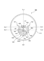
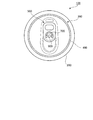
図1は、本実施の形態が適用される飲料缶100の上面図である。この飲料缶100は、同図(A)に示すように、上部に開口を有するとともに下部に底部を有し且つ筒状に形成された容器本体(缶胴)200と、容器本体200の開口に取り付けられ容器本体200の開口を塞ぐ缶蓋300とを有している。なお飲料缶100の内部には、清涼飲料、炭酸飲料、アルコール飲料などの飲料が充填(収容)されている。
Embodiments of the present invention will be described below in detail with reference to the accompanying drawings.
FIG. 1 is a top view of a beverage can 100 to which the present embodiment is applied. As shown in FIG. 1A, the beverage can 100 has a container body (can body) 200 having an opening in the upper part and a bottom part in the lower part and formed in a cylindrical shape, and an opening in the
缶蓋300は、円盤状に形成され基板として機能するパネル400を有している。また缶蓋300は、ユーザにより操作されるタブ500を有している。ここで、タブ500は、パネル400に取り付けられている。またタブ500は、パネル400の中央部側からパネル400の周縁部側に向かう一方向に沿って配置されている。付言すると、タブ500は後述する第1仮想線CL1に沿うように配置されている。またタブ500は、一端部および他端部を有し、ユーザにより他端部が操作されることで、パネル400のうちの予め定められた箇所(詳細は後述)に対して一端部を押し付け、パネル400を押圧する。なお本実施形態における缶蓋300は、飲み口として機能する開口がパネル400に形成された後もタブ500がパネル400に取り付けられた状態を維持するいわゆるステイオンタイプの缶蓋である。
The
ここで本実施形態では、タブ500は、パネル400の中央部(中心)からずれた位置に設けられたリベット900によってパネル400に固定されている。付言すると、タブ500は、パネル400に対して偏心した状態で設けられたリベット900によってパネル400に固定されている。さらに説明すると、パネル400のうちのタブ500により押圧される部位よりもパネル400の中央部側に設けられたリベット900によって、タブ500はパネル400に固定されている。さらにタブ500は、タブ500のうちの一端部(先端部510)と他端部との間に位置する部位がリベット900によってパネル400に固定されている。
Here, in the present embodiment, the
なお本実施形態では、タブ500が、パネル400の中央部からずれた位置に設けられたリベット900によってパネル400に固定されている場合を一例に説明するが、タブ500は、パネル400の中央部に設けられたリベット900によってパネル400に固定することもできる。また図1(A)ではタブ500が略矩形状の形成された場合を示したが、同図(B)に示すように、タブ500は、その先端部(タブノーズ)510を円弧状に形成することもできる。
In the present embodiment, a case where the
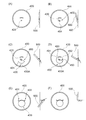
図2は、タブ500が取り付けられる前のパネル400の状態を示した正面図である。
パネル400は、上記のとおり円盤状に形成されている。またパネル400は、曲げ加工が施された外周縁410を有している。本実施形態では、この外周縁410と容器本体200の上縁部(不図示)とが互いに接触した状態で、この外周縁410および上縁部に対しいわゆる巻き締め加工が施される。これにより、パネル400が容器本体200の上縁部に固定される。またパネル400には、タブ500がパネル400に固定される際に押しつぶされ上述したリベット900となる突出部(ニップル)420が形成されている。ここでこの突出部420は、パネル400の中心部CPから外れた箇所に設けられている。
FIG. 2 is a front view showing a state of the
The
また本実施形態では、パネル400の表面に、第1スコア線430が形成されている。この第1スコア線430は、パネル400の表面に形成された溝により構成されており、パネル400の破断(後述)を誘導する役割を果たす。付言すると、第1スコア線430は、パネル400の破断が予定されている破断予定線として捉えることができる。また第1スコア線430は、パネル400の外周縁(周縁)410側に向かって膨らむように形成され、パネル400を正面から眺めた場合に略U字状に形成されている。さらに第1スコア線430は、パネル400の中心部CP側に一端部431および他端部432を有し、パネル400の外周縁(周縁)410側に頂部433Aを有している。
In the present embodiment, the
ここで、第1スコア線430の一端部431は、パネル400の中心部CPとパネル400に形成された突出部420とを結ぶ第1仮想線CL1の一方側に配置されている。また他端部432は、第1仮想線CL1を挟み上記一端部431が設けられている側とは反対側に設けられている。また、一端部431および他端部432が互いに離れた状態で設けられることによって、一端部431と他端部432との間には、第1スコア線430が設けられていない不連続部が設けられた状態となっている。この不連続部が設けられることによって、後述する舌片部がパネル400から離脱せず舌片部がパネル400に取り付いたままの状態となる。
Here, one
また、上記第1仮想線CL1と直交する仮想線であって突出部420を通る第2仮想線CL2を想定した場合に、上記一端部431および他端部432は、この第2仮想線CL2よりもパネル400の中心部(中央部)CP側に設けられている。付言すると、図1において、一端部431および他端部432は、リベット900よりも上方に設けられている。また上記第1仮想線CL1と直交する仮想線であってパネル400の中心部CPを通る第3仮想線CL3を挟んで相対する2つの領域のうちの一方の領域内に頂部433Aが設けられ、他方の領域内に一端部431および他端部432が設けられている。さらに、この一方の領域内に、突出部420が設けられている。突出部420をこのように一方の領域内に設けた場合、突出部420をパネル400の中心部CPに設ける場合に比べ、舌片部(後述)を曲げる際に要する操作荷重が小さくなる。
In addition, when assuming a second virtual line CL2 that is a virtual line orthogonal to the first virtual line CL1 and passes through the projecting
さらに説明すると、リベット900となる突出部420は、パネル400のうちの第1スコア線430により囲まれている部位であって、第1スコア線430の一端部431および他端部432よりも頂部433A側に位置する部位に設けられている。また第1スコア線430は、図2に示すように湾曲部433を有している。この湾曲部433は、一端部431と他端部432とを結ぶとともに突出部420が設けられている側に膨らみ且つ突出部420よりもパネル400の外周縁410側を通るように設けられている。
More specifically, the
また湾曲部433は、第1仮想線CL1と交わる箇所に頂部433Aを有している。また本実施形態における缶蓋300では、パネル400のうち第1スコア線430により囲まれた領域内に、この第1スコア線430により囲まれた領域の剛性を高める補強用ビードHBが形成されている。また補強用ビードHBの一端部には、上方(飲料缶100の外側)に向かって突出しタブ500の先端により押圧されるエンボスEBが設けられている。このエンボスEBが設けられることによって、エンボスEBがない場合に比べ、第2スコア線450(詳細は後述)におけるパネル400の破断が生じやすくなる。なお、本実施形態では第2スコア線450は直線で記載されているが、直線に限定されるものではなく、曲線その他の線であっても構わない。
Further, the
ここで本実施形態では、ユーザによりタブ500が操作されることで、第1スコア線430により囲まれた領域がタブ500により押圧され、第1スコア線430が形成されている箇所にてパネル400の破断が生じる(詳細は後述)。これにより、第1スコア線430が形成されている領域が舌片状となり、且つ、この領域が飲料缶100の内部に向かって折れ曲がる。これにより、飲料缶100に飲み口としての役割を果たす開口が形成される。なお本明細書では、第1スコア線430にて生じる破断により形成される上記舌片状の部位を舌片部と称する場合がある。また本実施形態では、第2スコア線450(詳細は後述)の湾曲部454(パネル400の破断が最初に生じる箇所)がパネル400の中心部CP側に寄せられて配置されている。このような場合、パネル400の外周縁410側にてパネル400の破断が最初に生じる場合に比べ、内部の飲料がこぼれにくくなる。
Here, in the present embodiment, when the
また本実施形態では、パネル400の表面に、第2スコア線450が形成されている。なおこの第2スコア線450も、パネル400の表面に形成された溝により構成されており、パネル400の破断を誘導する役割を果たす。第2スコア線450は、第2仮想線CL2を挟み相対する2つの領域のうちの、頂部433A(第1スコア線430の頂部433A)が設けられている領域内に設けられている。
In the present embodiment, the
また第2スコア線450は、一端部451および他端部452を有している。ここで第2スコア線450の他端部452は、第1スコア線430の湾曲部433に接続されている。なお本実施形態では、一端部431、他端部432、一端部451の3つの端部がスコア線に設けられた状態となっている。ここで第2スコア線450についてさらに説明すると、第2スコア線450の他端部452は、第1スコア線430の湾曲部433のうちの第1仮想線CL1と第2仮想線CL2との間に位置する部位に接続されている。さらに詳細に説明すると、第2スコア線450の他端部452は、第1スコア線430のうちの頂部433Aと他端部432との間に位置する部位に接続されている。
The
このため本実施形態では、第1スコア線430と第2スコア線450との接続部と第1スコア線430の一端部431との距離の方が、接続部と第1スコア線430の他端部432との距離よりも大きくなっている。付言すると、第1スコア線430のうちの一端部431と上記接続部との間に位置する部位の長さの方が、第1スコア線430のうちの他端部432と上記接続部との間に位置する部位の長さよりも大きくなっている。なお本実施形態では、図中右下方向に向かうように第2スコア線450が設けられている場合を説明したが、第2スコア線450は、図中左下方向に向かうように設けてもよい。この場合、第2スコア線450は、第1スコア線430のうちの頂部433Aと一端部431との間に位置する部位に接続されることになる。
For this reason, in this embodiment, the distance between the connection portion between the
一方、第2スコア線450の一端部451は、突出部420の近傍に設けられている。さらに説明すると、第2スコア線450の一端部451は、第1仮想線CL1を挟んで相対する2つの領域のうちの一方の領域側に配置され、第2スコア線450の他端部452はこの2つの領域のうちの他方の領域側に配置されている。さらに説明すると、第2スコア線450は、他端部452から突出部420に向かう直線部453を有している。さらに、この直線部453に接続されるとともに円柱状に形成された突出部420との間に距離を有して配置され且つ突出部420に沿うように設けられた湾曲部454を有している。
On the other hand, one
ここで湾曲部454は、突出部420と第1スコア線430との間に形成されている。より詳細には、第1スコア線430の頂部433Aと突出部420との間に形成されている。付言すると、第1仮想線CL1上において、突出部420と第1スコア線430との間に、第2スコア線450の湾曲部454が配置されている。
Here, the
また湾曲部454は、パネル400のうちのタブ500により押圧される領域RA(タブ500により押圧される部位)と突出部420との間を通過するように設けられている。また湾曲部454は、タブ500により押圧される領域RAと突出部420とを通る第1仮想線CL1(領域RAと突出部420とを通る直線)と交差するように設けられている。さらに説明すると、本実施形態における第2スコア線450は、領域RAと突出部420との間を通過した後、第1仮想線CL1と交差する方向に向かって進行し、第1スコア線430に接続される。付言すると、本実施形態における第2スコア線450は、第1仮想線CL1の配設方向と交差する方向に沿うように形成されている。さらに説明すると、第2スコア線450は、タブ500(図1参照)の配設方向と交差する方向に沿うように形成されている。
The
さらに説明すると、第1仮想線CL1と交差する方向に向かって進行する第2スコア線450は、領域RAが位置する側および突出部420が設けられている側のうちの領域RAが位置する側に次第に近づくように進行を行う。より具体的には、領域RAが位置する側に、第2スコア線450の直線部453が次第に近づくように、第2スコア線450は第1スコア線430に向かって進んでいく。
More specifically, the
さらに説明すると、第2スコア線450は、領域RAと突出部420との間を通過した後、第2仮想線CL2から次第に離れるように進行し、第1スコア線430に接続される。付言すると、第2スコア線450は、領域RAと突出部420との間を通過した後、第1スコア線430の頂部433Aとパネル400の中心部CPとを通る直線に直交する直線であって突出部420を通る直線である第2仮想線CL2から次第に離れるように進行し、第1スコア線430に接続される。
More specifically, after passing between the region RA and the
ここで図3(パネル400の状態を説明するための図)も参照しながら、タブ500が操作された際のパネル400の状態を説明する。なお、図3では、パネル400を正面から眺めた場合の状態、および、パネル400を側方から眺めた場合の状態を図示している。
Here, the state of the
本実施形態では、タブ500の後端部がユーザにより持ちあげられた際、タブ500の先端部(タブノーズ)510(図1参照)が、第2スコア線450の湾曲部454と第1スコア線430の頂部433Aとの間に位置する上記領域RA(図2参照)を押圧する。そして領域RAがタブ500により押圧されると、まず、この領域RAとリベット900(突出部420)との間を通過するように設けられた第2スコア線450の湾曲部454にてパネル400が破断する(図3の(B)参照)。その後、第2スコア線450に沿ってパネル400の破断が進行し、第1スコア線430と第2スコア線450との接続部まで、パネル400が破断した状態となる。
In the present embodiment, when the rear end portion of the
ここで本実施形態では、第1スコア線430と第2スコア線450との上記接続部にて、スコア線が分岐した状態となっている。このため、第2スコア線450の上記湾曲部454から上記接続部までパネル400の破断が進行した後、本実施形態では、図3の(C)に示すように、接続部から頂部433Aを経て第1スコア線430の一端部431まで破断が進行する。また、図3の(D)に示すように、接続部から第1スコア線430の他端部432に向かっての破断も進行する。
Here, in the present embodiment, the score line is branched at the connecting portion between the
これにより、第1スコア線430により囲まれていた領域が上述した舌片部となる。また、舌片部の根元(第1スコア線430の一端部431と他端部432との間に位置する箇所)にて舌片部は折り曲げられ、図3(E)に示すように、舌片部は飲料缶100の内部に進入する。これにより飲料缶100には飲み口として機能する開口が形成される。なお詳細は後述するが、引き起こされたタブ500が元の状態に戻される際には、図3(F)に示すように、タブ500が折れ曲がる。
Thereby, the region surrounded by the
なお本実施形態では、図2に示すように、第1スコア線430の一端部431と他端部432との間に位置する領域に、溝600が設けられている。この溝600は、円弧を描き湾曲して形成されるとともに第1スコア線430の一端部431が設けられている側から他端部432が設けられている側に向かうように設けられている。付言すると、第2仮想線CL2(第3仮想線CL3)に沿うように設けられている。このため本実施形態における飲料缶100では、舌片部の折れ曲がりが生じやすくなっている。また本実施形態では、溝600が湾曲して形成されているため、曲がった舌片部が元の状態に戻りにくくなっている。なお溝600は必ずしも必要ではなく溝600は省略することもできる。
In the present embodiment, as shown in FIG. 2, a
次にタブ500について詳細に説明する。
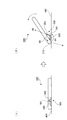
図4および図5は、タブ500を説明するための図である。また図6は、ユーザによりタブ500が操作されパネル400に開口が形成された際の状態を示した図である。なお図4(A)はタブ500の正面図であり、同図(B)は同図(A)の矢印IVB方向からタブ500を眺めた場合の図である。また、同図(C)はタブ500の裏面図である。付言すると、パネル400と対向する対向面側からタブ500を眺めた場合の図である。また同図(D)は、同図(A)の矢印IVD方向からタブ500を眺めた場合の図である。また図5(A)はタブ500に設けられた伸長部(後述)を説明するための図であり、同図(B)はタブ500が引き起こされた際の状態を示した図である。
Next, the
4 and 5 are diagrams for explaining the
本実施形態におけるタブ500は、図4(A)に示すように、板状に形成され且つ矩形状に形成されたタブ本体部520を有している。なお本実施形態では、同図(D)に示すように、このタブ本体部520の外周縁に対して曲げ加工(カール加工)が施され、タブ本体部520の外周縁が内側にカールした状態となっている。付言すると、タブ本体部520に四方に設けられている縁部には、カール部が形成されている。これにより本実施形態のタブ500は曲げ剛性が高められている。さらにタブ500には、パネル400を押圧する先端部510が設けられている側とは反対側(タブテール側)に、ユーザの指が引っ掛けられる貫通孔(フィンガーホール)530が形成されている。
As shown in FIG. 4A, the
またタブ500には、タブ500の先端部510側に、パネル400に設けられた突出部420(図2参照)が挿入される挿入孔540が形成されている。さらに、タブ500の長手方向に沿った長穴550が、タブ500の先端部510側に形成されている。ここで、この長穴550は、タブ500の幅方向(長手方向と直交する方向)において、2つ並んだ状態で設けられている。なお本実施形態では、この2つの長穴550の間に挿入孔540が設けられている。また、挿入孔540よりもタブ500の後端側であって、上記2つの長穴550の間に位置する領域には、伸長部560が形成されている。
Further, the
ここで伸長部560では、図5(A)に示すように、板状に形成された上記タブ本体部520(図4(A)参照)に対して曲げ加工が施されており、伸長部560には、互いに交差する関係の第1片部561および第2片部562が設けられている。付言すると、伸長部560には、タブ本体部520を構成する板部材が屈曲した屈曲部が形成された状態となっている。ここで第1片部561は、タブ500の後端部に向かうに従いパネル400から離れるように配置されている。また第2片部562は、第1片部561に前端部が接続されタブ500の後端部に向かうに従いパネル400に接近するように配置されている。
Here, in the
また図4(A)を参照してタブ500についてさらに説明を行うと、タブ本体部520の四方に設けられた4つのカール部のうちタブ500の長手方向に沿って設けられたカール部には第1スリット521が形成されている。また4つのカール部のうちタブ500の長手方向に沿って設けられたもう一つのカール部には、第2スリット522が形成されている。さらに、タブ本体部520のうち第1スリット521と第2スリット522との間に位置する部位には、溝523が形成されている。
Further, the
ここで、第1スリット521、第2スリット522、溝523は、互いに接続され連続した状態で設けられている。また、第1スリット521、第2スリット522、溝523は、タブ500の幅方向に沿って設けられている。また、第1スリット521、第2スリット522、溝523は、挿入孔540と貫通孔530との間に配置されている。ここで本実施形態では、このように第1スリット521、第2スリット522、溝523が形成されており、これらが形成された部分の剛性(曲げ剛性)が低下している。
Here, the
このため、図4(B)に示すように、タブ500の後端部側に荷重を加えるとタブ500が折れ曲がるようになる。付言するとタブ500が屈曲するようになる。なお本実施形態では、第1スリット521と第2スリット522との間に溝523を形成してこの部分の剛性を低下させたが、このような溝に限らず、例えば曲げ加工を施すことで剛性を低下させることができる。また溝523は必ずしも必要ではなく溝523は省略することもできる。
For this reason, as shown in FIG. 4B, when a load is applied to the rear end side of the
次にタブ500が操作された際の各部の状態を説明する。
ユーザによりタブ500が操作される際には、タブ500の後端部とパネル400との間にユーザの指が挿入され、図5(B)に示すように、タブ500が引き起こされる。ここでこの際、まず、第1片部561と第2片部562とにより形成された伸長部560が延びるようになる。付言すると、第1片部561と第2片部562とによって折れ曲がった状態にあった伸長部560が直線状となり、伸長部560が伸びるようになる。そして、伸長部560が伸びきると、伸長部560からリベット900に荷重が伝わるようになり、リベット900を上方に引っ張り上げようとする力がリベット900に作用する。
Next, the state of each part when the
When the user operates the
その一方で、タブ500の先端部510がパネル400に接触しており、パネル400を下方に向かって押圧する力がパネル400に作用する。これにより、タブ500の先端部510とリベット900との間に位置する、第2スコア線450の湾曲部454(図2参照)にて、パネル400の破断が発生する。その後、上記にて説明したように、第2スコア線450に沿って破断が進行し、次いで、第1スコア線430に沿って破断が進行する。これにより、第1スコア線430により囲まれていた領域に舌片部が形成される。また、第1スコア線430により囲まれていた領域に開口が形成される。
On the other hand, the
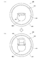
また上記のように、伸長部560が伸び伸長部560からリベット900に荷重が伝わるようになると、図5(B)の矢印4Aに示すような回転モーメントが舌片部に作用する。これにより、舌片部の根元を中心として舌片部が回転し、この根元にて舌片部の折れ曲がりが生じる。また、この折れ曲がりによって舌片部が飲料缶100の内部に進入していく。さらに、舌片部の飲料缶100の内部への進入により、図6(A)に示すように、タブ500の先端部側が飲料缶100の内部へ入り込む。
Further, as described above, when the
なお図6(A)は、タブ500が起立しパネル400とタブ500とが直交している状態を示している。その後、引き起こされたタブ500がユーザにより元の状態に戻されることとなるが、この際、上記にて説明した、第1スリット521、第2スリット522、および溝523にて、タブ500の折れ曲がりが生じるようになる。この結果、図6(B)に示すように、タブ500の後端部側がパネル400に沿うようになる。その一方で、タブ500の先端部側は飲料缶100の内部に入り込んだ状態となる。
FIG. 6A shows a state in which the
ここで飲料缶100の直径を小さくしたい場合(パネル400が小さくなる場合)、第1スコア線430により囲まれた領域(開口となる領域、舌片部となる領域)とタブ500とを接近させて配置する必要が生じる。ところでこの場合、第1スコア線430により囲まれた領域とタブ500とが重なる領域の面積が大きくなる。また開口(飲み口)を大きくした場合にも、第1スコア線430により囲まれた領域とタブ500とが重なる領域の面積が大きくなる。ところでこの場合、内部の飲料が出にくくなったりしユーザは飲料を飲みにくくなる。このため本実施形態では、上記のように、タブ500のうち飲み口と重なる部分(舌片部と重なる部分)を飲料缶100の内部に入り込ませる構成としている。この場合、開口の面積が大きくなり、タブ500の先端側が飲料缶100の内部に入り込まない構成に比べ、ユーザは内部の飲料を飲みやすくなる。
Here, when it is desired to reduce the diameter of the beverage can 100 (when the
なお図7(缶蓋300の他の構成例を示した図)に示すように、リベット900により固定される部位の周囲にスリット700が設けられたタブ500が使用されることも多い。ところでこのようなタブ500を図2にて示したパネル400に取り付けた場合、スリット700が設けられているためにリベット900を上方に引き上げる力(引っ張る力)(図5(B)の符号4B参照)はリベット900に働かず、図5(B)の矢印4Aで示した回転モーメントはかからなくなる。そしてこの場合、舌片部の根元での舌片部の折れ曲がりが生じにくくなる。付言するとリベット900が設けられている箇所にて舌片部の折れ曲がりが生じるようになるが、舌片部の根元での舌片部の折れ曲がりは生じにくくなる。そしてこの場合、パネル400に形成される開口が小さいものとなってしまう。
In addition, as shown in FIG. 7 (a diagram showing another example of the structure of the can lid 300), a
このため本実施形態では、タブ500のうちリベット900の後方に位置する部位と、このリベット900とを伸長部560で接続する構成としている。この構成によって、リベット900を上方に引き上げる力が大きくなり、舌片部に作用する回転モーメントが大きくなる。これにより、舌片部の根元にて舌片部の曲がりが生じ舌片部の全体が飲料缶100の内部に進入するようになる。
For this reason, in this embodiment, it is set as the structure which connects the site | part located behind the
なお伸長部560を設けない構成であっても上記回転モーメントを大きくすることができる。例えば、タブ500のうちのリベット900の後方に位置する部位と、このリベット900とを単に接続するだけでも、回転モーメントは大きくなる。しかしながらこの場合、タブ500を引き起こす際の操作性が低下してしまう。
Note that the rotational moment can be increased even in a configuration in which the extending
より具体的に説明すると、通常、タブ500を引き起こす際には、タブ500とパネル400との間に指が入れられたうえでタブ500の引き起こしが行われる。ところで、上記のように、リベット900の後方に位置する部位とリベット900とを接続した場合、タブ500の変位(タブ500の後端部の上方への変位)がリベット900により規制され、タブ500の変位が起こりにくくなってしまう。そしてこの場合、ユーザの指がパネル400とタブ500との間に入りこみにくくなり、タブ500を引き起こす際の操作性が低下する。
More specifically, when the
このため本実施形態では、伸長部560を設ける構成としている。このように伸長部560を設けた場合、タブ500が予め定められた所定の角度(例えば60°)となるまでは伸長部560が伸びるようになり、タブ500がこの予め定められた所定の角度となるまで、タブ500の変位のリベット900による規制がなされにくくなる。そしてこのように規制がなされにくくなると、タブ500とパネル400との間に指が入りやすくなる。この結果、本実施形態の構成では、タブ500を引き起こす際の操作性の低下が抑制される。
For this reason, in this embodiment, the extending
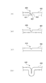
なお図2にて示した溝600の形状に特に制限はないが、溝600は、図8に示す形状で形成することができる。図8は、溝600の形状の一例を示した図である。溝600は、例えば、同図(A)に示すように、パネル400の表面と略直交する関係を有する第1側面621、第2側面622、および、第1側面621と第2側面622とを接続する平坦な底面623とを有する形状で形成することができる。なお溝600の底部には、同図(B)に示すように曲率を付与してもよい。また溝600は、同図(C)に示すように、断面が三角形となる形状で形成することもできる。なお、上記では、溝600を形成することで、舌片部の根元の剛性を低下させたが、同図(D)に示すように、曲げ加工を舌片部の根元に対して施すことで、剛性を低下させることもできる。
The shape of the
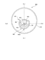
図9は、パネル400の比較例を示した図である。
図9に示すパネル400では、上記にて説明した第2スコア線450は設けられていない。また本パネル400では、上記第1スコア線430に相当するスコア線460が設けられている。ここで、図2にて示した第1スコア線430は、第1仮想線CL1を中心として線対象となる関係で形成されていたが、本実施形態におけるスコア線460は、線対象となる関係で配置されていない。
FIG. 9 is a view showing a comparative example of the
In the
ここでスコア線460は、上記第1スコア線430と同様に、一端部461および他端部462を有している。また、一端部461からスコア線460の頂部460Aにかけての形状は、上記第1スコア線430における一端部431から頂部433A(図2参照)にかけての形状と同じとなっている。その一方で、頂部460Aから他端部462にかけての形状は、第1スコア線430の頂部433Aから他端部432にかけての形状とは異なっている。
Here, the
より具体的に説明すると、スコア線460の他端部462は、突出部420の近傍に設けられている。またこの他端部462は、第1仮想線CL1を挟んで相対する2つの領域のうち、一端部461が設けられている領域内に設けられている。そして本実施形態では、この他端部462を始点とし一端部461を終点としてスコア線460が延びている。より詳細に説明すると、他端部462を出発点として、スコア線460は、まず、突出部420と頂部460Aとの間を通過する。
More specifically, the
その後、スコア線460は、突出部420の周囲を且つスコア線460の頂部460Aが設けられている側とは反対側に向かって進行していく。その後、スコア線460は、屈曲し、その進行方向を逆転する。より詳細に説明すると、突出部420から離れる方向且つパネル400の外周縁410に向かう方向に向かって円弧を描きながら進行する。さらにスコア線460は、スコア線460の頂部460Aに向かって進行していく。そして最後に、スコア線460は一端部461に到達する。なお、スコア線460のうち上記屈曲する部位を、本明細書では、以下「屈曲部」と称する。
Thereafter, the
ここでタブ500が操作され飲料缶100に開口が形成される際には、上記と同様、スコア線460のうち突出部420とスコア線460の頂部460Aとの間に位置する部位にて、パネル400の破断が生じる。その後、パネル400の破断が、スコア線460の頂部460Aを経由してスコア線460の上記一端部461まで進行していく。これにより上記と同様、舌片部が形成され、飲み口となる開口がパネル400に形成される。ここで図9にて示したスコア線460では、上記のとおり屈曲部が形成されている。このため、上記図2にて示したパネル400の方が、図9で示したパネル400よりも、パネル400の破断が進行しやすくなっている。
Here, when the
さらに説明すると、図9のように、突出部420が舌片部の根元ではなく舌片部の中央部に設けられ、且つ、第2スコア線450を設けず上記スコア線460のように一つのスコア線のみが設けられる場合、上記のように屈曲部が形成されてしまう。そしてこのように屈曲部が形成されると、パネル400の破断が進行しにくい状況となる。一方、図2に示した本実施形態の構成では、図9と同様、突出部420が舌片部の中央部に設けられているが、第2スコア線450が設けられているために、上記のような屈曲部が形成されないようになっている。このため本実施形態の構成では、突出部420が舌片部の中央部に設けられているにも関わらず、パネル400の破断が進行しやすくなっている。
More specifically, as shown in FIG. 9, the
また図9に示した態様では、タブ500からの荷重がパネル400に作用する荷重作用点(上記領域RAに相当)と、スコア線460との離間距離が、他端部462から上記屈曲部に向けてスコア線460が進行するのに従い大きくなる。そしてこのように離間距離が大きくなると、スコア線460に対して荷重が作用しにくくなり、パネル400の破断が生じにくくなる。そしてこの場合、パネル400に開口を形成する際のタブ500の操作荷重が増大することとなる。
In the embodiment shown in FIG. 9, the distance between the load application point at which the load from the
一方で、本実施形態における構成では、図2に示すように、第1スコア線430の一端部431や他端部432に対して第2スコア線450が接続せず、第1スコア線430のうちの一端部431と他端部432との間に位置する部位に対して、第2スコア線450が接続する構成となっており、図9に示した態様に比べ、上記荷重作用点とスコア線との離間距離が小さくなる。このため本実施形態の構成では、図9にて示した態様に比して、パネル400に開口を形成する際のタブ500の操作荷重が小さくなる。
On the other hand, in the configuration of the present embodiment, as shown in FIG. 2, the
なお本実施形態では、図2にて示したように、第2仮想線CL2から次第に離れるように第2スコア線450が設けられた場合を一例に説明したが、第1スコア線430のうちの一端部431と他端部432との間に位置する部位に第2スコア線450が接続する構成であれば、図9の態様に比べ、スコア線の破断は進行しやすくなり、パネル400に開口を形成する際のタブ500の操作荷重は小さくなる。
In the present embodiment, as illustrated in FIG. 2, the case where the
例えば、突出部420が設けられている側に第2スコア線450が次第に近づくように第2スコア線450が進行を行う場合(第2仮想線CL2に次第に近づくように進行を行う場合)であっても、一端部431と他端部432との間に位置する上記部位に第2スコア線450が接続する構成であれば、図9の態様に比べ、スコア線の破断は進行しやすくなる。そしてこの場合、図9の態様に比べタブ500の操作荷重は小さくなる。
なおスコア線の破断をより円滑に進行させタブ500の操作荷重をより低減させる場合には、図2に示したように、第2仮想線CL2から次第に離れるように第2スコア線450を設けることが好ましくなる。付言すると、図2に示したように、第2仮想線CL2から次第に離れるように第2スコア線450を設けた場合、第2仮想線CL2に次第に近づくように第2スコア線450を設けた場合に比べ、パネル400のうちのタブ500により押圧される領域RAに対して、第2スコア線450がより近づくようになる。そしてこの場合、第2仮想線CL2に次第に近づくように第2スコア線450を設けた場合に比べ、スコア線の破断は進行しやすくなり、タブ500の操作荷重が小さくなる。
For example, this is a case where the
When the score line breaks more smoothly and the operation load on the
100…飲料缶、200…容器本体、300…缶蓋、400…パネル、410…外周縁、430…第1スコア線、431…一端部、432…他端部、433A…頂部、450…第2スコア線、500…タブ、900…リベット、CL1…第1仮想線、CL2…第2仮想線
DESCRIPTION OF
Claims (5)
前記パネルに形成され、当該パネルの中心部側および周縁部側のうちの当該中心部側に一端および他端を有するとともに当該周縁部側に向かって膨らむように形成された第1のスコア線と、
一端部および他端部を有し、前記パネルの中央部側から当該パネルの周縁部側に向かう一方向に沿って配置され、当該パネルのうちの前記第1のスコア線により囲まれている部位を押圧するタブと、
前記タブのうちの前記一端部と前記他端部との間に位置する部位を前記パネルに対して固定するリベットと、
前記パネルのうちの前記タブにより押圧される部位と前記リベットとの間を通過するように設けられるとともに前記一方向と交差する方向に沿って形成され、前記第1のスコア線のうちの前記一端と前記他端との間に位置する部位に接続される第2のスコア線と、
を備える缶蓋。 A panel attached to the opening of the can body;
A first score line formed on the panel, having one end and the other end on the center side of the center side and the periphery side of the panel and bulging toward the periphery side; ,
The part which has one end part and the other end part, is arrange | positioned along one direction which goes to the peripheral part side of the said panel from the center part side of the said panel, and is enclosed by the said 1st score line of the said panel A tab to press,
A rivet for fixing a portion of the tab located between the one end and the other end to the panel;
The one end of the first score line is formed so as to pass between a portion pressed by the tab of the panel and the rivet, and is formed along a direction intersecting the one direction. And a second score line connected to a portion located between the second end and the other end;
Can lid with.
前記第2のスコア線は、前記タブにより押圧される前記部位と前記リベットとの間を通過した後、前記第1のスコア線の前記頂部と前記パネルの中心部とを通る直線に直交する直線であって当該リベットを通る直線から離れるように進行し、当該第1のスコア線に接続されることを特徴とする請求項1記載の缶蓋。 The first score line formed so as to swell toward the peripheral edge side of the panel has a top on the peripheral edge side,
The second score line is a straight line orthogonal to a straight line passing through the top of the first score line and the center of the panel after passing between the portion pressed by the tab and the rivet. The can lid according to claim 1, wherein the can lid travels away from a straight line passing through the rivet and is connected to the first score line.
前記第2のスコア線は、前記第1のスコア線のうちの前記頂部と前記一端との間に位置する部位、又は、当該第1のスコア線のうちの当該頂部と前記他端との間に位置する部位に接続して設けられていることを特徴とする請求項1記載の缶蓋。 The first score line formed so as to swell toward the peripheral edge side of the panel has a top on the peripheral edge side,
The second score line is a portion located between the top and the one end of the first score line, or between the top and the other end of the first score line. The can lid according to claim 1, wherein the can lid is provided by being connected to a portion located at a position.
前記缶蓋は、
前記缶胴の前記開口に取り付けられるパネルと、
前記パネルに形成され、当該パネルの中心部側および周縁部側のうちの当該中心部側に一端および他端を有するとともに当該周縁部側に向かって膨らむように形成された第1のスコア線と、
一端部および他端部を有し、前記パネルの中央部側から当該パネルの周縁部側に向かう一方向に沿って配置され、当該パネルのうちの前記第1のスコア線により囲まれている部位を押圧するタブと、
前記タブのうちの前記一端部と前記他端部との間に位置する部位を前記パネルに対して固定するリベットと、
前記パネルのうちの前記タブにより押圧される部位と前記リベットとの間を通過するように設けられるとともに前記一方向と交差する方向に沿って形成され、前記第1のスコア線のうちの前記一端と前記他端との間に位置する部位に接続される第2のスコア線と、
を備えていることを特徴とする飲料缶。 A can body having an opening and containing a beverage therein; and a can lid for closing the opening of the can body,
The can lid is
A panel attached to the opening of the can body;
A first score line formed on the panel, having one end and the other end on the center side of the center side and the periphery side of the panel and bulging toward the periphery side; ,
The part which has one end part and the other end part, is arrange | positioned along one direction which goes to the peripheral part side of the said panel from the center part side of the said panel, and is enclosed by the said 1st score line of the said panel A tab to press,
A rivet for fixing a portion of the tab located between the one end and the other end to the panel;
The one end of the first score line is formed so as to pass between a portion pressed by the tab of the panel and the rivet, and is formed along a direction intersecting the one direction. And a second score line connected to a portion located between the second end and the other end;
A beverage can characterized by comprising:
Priority Applications (1)
| Application Number | Priority Date | Filing Date | Title |
|---|---|---|---|
| JP2011005431A JP5643119B2 (en) | 2011-01-14 | 2011-01-14 | Can lid and beverage can |
Applications Claiming Priority (1)
| Application Number | Priority Date | Filing Date | Title |
|---|---|---|---|
| JP2011005431A JP5643119B2 (en) | 2011-01-14 | 2011-01-14 | Can lid and beverage can |
Publications (2)
| Publication Number | Publication Date |
|---|---|
| JP2012144286A true JP2012144286A (en) | 2012-08-02 |
| JP5643119B2 JP5643119B2 (en) | 2014-12-17 |
Family
ID=46788299
Family Applications (1)
| Application Number | Title | Priority Date | Filing Date |
|---|---|---|---|
| JP2011005431A Expired - Fee Related JP5643119B2 (en) | 2011-01-14 | 2011-01-14 | Can lid and beverage can |
Country Status (1)
| Country | Link |
|---|---|
| JP (1) | JP5643119B2 (en) |
Cited By (2)
| Publication number | Priority date | Publication date | Assignee | Title |
|---|---|---|---|---|
| JP2012166826A (en) * | 2011-02-15 | 2012-09-06 | Showa Aluminum Kan Kk | Can lid and beverage can |
| WO2014148246A1 (en) * | 2013-03-22 | 2014-09-25 | 昭和アルミニウム缶株式会社 | Method for manufacturing can lid, can lid, and can body |
Citations (5)
| Publication number | Priority date | Publication date | Assignee | Title |
|---|---|---|---|---|
| JPS6328633U (en) * | 1986-08-08 | 1988-02-25 | ||
| JPH06336247A (en) * | 1993-05-26 | 1994-12-06 | Biramonte R D Kk | Can lid |
| JPH10167265A (en) * | 1996-12-02 | 1998-06-23 | Biramonte R D Kk | Can lid |
| JP2008168923A (en) * | 2007-01-11 | 2008-07-24 | Universal Seikan Kk | Can lid |
| JP2008213934A (en) * | 2007-02-28 | 2008-09-18 | Hyun Jin Cho | Can lid having improved unsealability and drinking property |
-
2011
- 2011-01-14 JP JP2011005431A patent/JP5643119B2/en not_active Expired - Fee Related
Patent Citations (5)
| Publication number | Priority date | Publication date | Assignee | Title |
|---|---|---|---|---|
| JPS6328633U (en) * | 1986-08-08 | 1988-02-25 | ||
| JPH06336247A (en) * | 1993-05-26 | 1994-12-06 | Biramonte R D Kk | Can lid |
| JPH10167265A (en) * | 1996-12-02 | 1998-06-23 | Biramonte R D Kk | Can lid |
| JP2008168923A (en) * | 2007-01-11 | 2008-07-24 | Universal Seikan Kk | Can lid |
| JP2008213934A (en) * | 2007-02-28 | 2008-09-18 | Hyun Jin Cho | Can lid having improved unsealability and drinking property |
Cited By (4)
| Publication number | Priority date | Publication date | Assignee | Title |
|---|---|---|---|---|
| JP2012166826A (en) * | 2011-02-15 | 2012-09-06 | Showa Aluminum Kan Kk | Can lid and beverage can |
| WO2014148246A1 (en) * | 2013-03-22 | 2014-09-25 | 昭和アルミニウム缶株式会社 | Method for manufacturing can lid, can lid, and can body |
| JP2014184454A (en) * | 2013-03-22 | 2014-10-02 | Showa Aluminum Kan Kk | Manufacturing method of can-top, can-top and can body |
| CN104955589A (en) * | 2013-03-22 | 2015-09-30 | 昭和铝罐株式会社 | Manufacturing method of can lid, can lid and can body |
Also Published As
| Publication number | Publication date |
|---|---|
| JP5643119B2 (en) | 2014-12-17 |
Similar Documents
| Publication | Publication Date | Title |
|---|---|---|
| JP5646362B2 (en) | Can lid and beverage can | |
| WO2014200098A1 (en) | Can lid and beverage can | |
| JP5643119B2 (en) | Can lid and beverage can | |
| JP5554256B2 (en) | Can lid and beverage can | |
| JP5698046B2 (en) | Can lid and beverage can | |
| CN104136335B (en) | Cover and beverage can | |
| JP6502625B2 (en) | Can lid and beverage can | |
| JP5591071B2 (en) | Can lid and beverage can | |
| JP5826868B2 (en) | Can lid and beverage can | |
| JP6009910B2 (en) | Can lid and beverage can | |
| JP5923574B2 (en) | Can lid and beverage can | |
| JP5913437B2 (en) | Can lid and beverage can | |
| JP5646294B2 (en) | Can lid and beverage can | |
| JP5902260B2 (en) | Can lid and beverage can | |
| JP5902261B2 (en) | Can lid and beverage can | |
| JP6168653B2 (en) | Can lid and beverage can | |
| JP5634917B2 (en) | Can lid and beverage can | |
| JP6335490B2 (en) | Can lid and beverage can | |
| JP6243207B2 (en) | Can lid and beverage can | |
| JP6466794B2 (en) | Can lid and beverage can | |
| JP5662849B2 (en) | Can lid and beverage can | |
| WO2016021434A1 (en) | Can lid and beverage can |
Legal Events
| Date | Code | Title | Description |
|---|---|---|---|
| A621 | Written request for application examination |
Free format text: JAPANESE INTERMEDIATE CODE: A621 Effective date: 20130826 |
|
| A977 | Report on retrieval |
Free format text: JAPANESE INTERMEDIATE CODE: A971007 Effective date: 20140326 |
|
| A131 | Notification of reasons for refusal |
Free format text: JAPANESE INTERMEDIATE CODE: A131 Effective date: 20140415 |
|
| A521 | Request for written amendment filed |
Free format text: JAPANESE INTERMEDIATE CODE: A523 Effective date: 20140609 |
|
| A131 | Notification of reasons for refusal |
Free format text: JAPANESE INTERMEDIATE CODE: A131 Effective date: 20140722 |
|
| A521 | Request for written amendment filed |
Free format text: JAPANESE INTERMEDIATE CODE: A523 Effective date: 20140911 |
|
| TRDD | Decision of grant or rejection written | ||
| A01 | Written decision to grant a patent or to grant a registration (utility model) |
Free format text: JAPANESE INTERMEDIATE CODE: A01 Effective date: 20141007 |
|
| A61 | First payment of annual fees (during grant procedure) |
Free format text: JAPANESE INTERMEDIATE CODE: A61 Effective date: 20141030 |
|
| R150 | Certificate of patent or registration of utility model |
Ref document number: 5643119 Country of ref document: JP Free format text: JAPANESE INTERMEDIATE CODE: R150 |
|
| R250 | Receipt of annual fees |
Free format text: JAPANESE INTERMEDIATE CODE: R250 |
|
| R250 | Receipt of annual fees |
Free format text: JAPANESE INTERMEDIATE CODE: R250 |
|
| S111 | Request for change of ownership or part of ownership |
Free format text: JAPANESE INTERMEDIATE CODE: R313111 |
|
| S533 | Written request for registration of change of name |
Free format text: JAPANESE INTERMEDIATE CODE: R313533 |
|
| R350 | Written notification of registration of transfer |
Free format text: JAPANESE INTERMEDIATE CODE: R350 |
|
| S531 | Written request for registration of change of domicile |
Free format text: JAPANESE INTERMEDIATE CODE: R313531 |
|
| S533 | Written request for registration of change of name |
Free format text: JAPANESE INTERMEDIATE CODE: R313533 |
|
| R350 | Written notification of registration of transfer |
Free format text: JAPANESE INTERMEDIATE CODE: R350 |
|
| LAPS | Cancellation because of no payment of annual fees |