JP2012144283A - Automatic liquid ejection device - Google Patents

Automatic liquid ejection device Download PDF

Info

Publication number
JP2012144283A
JP2012144283A JP2011005024A JP2011005024A JP2012144283A JP 2012144283 A JP2012144283 A JP 2012144283A JP 2011005024 A JP2011005024 A JP 2011005024A JP 2011005024 A JP2011005024 A JP 2011005024A JP 2012144283 A JP2012144283 A JP 2012144283A
Authority
JP
Japan
Prior art keywords
head
pump
pressing
container
liquid
Prior art date
Legal status (The legal status is an assumption and is not a legal conclusion. Google has not performed a legal analysis and makes no representation as to the accuracy of the status listed.)
Granted
Application number
JP2011005024A
Other languages
Japanese (ja)
Other versions
JP5220138B2 (en
Inventor
Masaki Ito
正樹 伊藤
Current Assignee (The listed assignees may be inaccurate. Google has not performed a legal analysis and makes no representation or warranty as to the accuracy of the list.)
Individual
Original Assignee
Individual
Priority date (The priority date is an assumption and is not a legal conclusion. Google has not performed a legal analysis and makes no representation as to the accuracy of the date listed.)
Filing date
Publication date
Application filed by Individual filed Critical Individual
Priority to JP2011005024A priority Critical patent/JP5220138B2/en
Priority to CN201220014856.0U priority patent/CN202761150U/en
Priority to PCT/JP2012/050601 priority patent/WO2012096377A1/en
Publication of JP2012144283A publication Critical patent/JP2012144283A/en
Application granted granted Critical
Publication of JP5220138B2 publication Critical patent/JP5220138B2/en
Expired - Fee Related legal-status Critical Current
Anticipated expiration legal-status Critical

Links

Images

Classifications

    • BPERFORMING OPERATIONS; TRANSPORTING
    • B05SPRAYING OR ATOMISING IN GENERAL; APPLYING FLUENT MATERIALS TO SURFACES, IN GENERAL
    • B05BSPRAYING APPARATUS; ATOMISING APPARATUS; NOZZLES
    • B05B9/00Spraying apparatus for discharge of liquids or other fluent material, without essentially mixing with gas or vapour
    • B05B9/03Spraying apparatus for discharge of liquids or other fluent material, without essentially mixing with gas or vapour characterised by means for supplying liquid or other fluent material
    • B05B9/04Spraying apparatus for discharge of liquids or other fluent material, without essentially mixing with gas or vapour characterised by means for supplying liquid or other fluent material with pressurised or compressible container; with pump
    • B05B9/08Apparatus to be carried on or by a person, e.g. of knapsack type
    • B05B9/085Apparatus to be carried on or by a person, e.g. of knapsack type with a liquid pump
    • B05B9/0855Apparatus to be carried on or by a person, e.g. of knapsack type with a liquid pump the pump being motor-driven
    • BPERFORMING OPERATIONS; TRANSPORTING
    • B05SPRAYING OR ATOMISING IN GENERAL; APPLYING FLUENT MATERIALS TO SURFACES, IN GENERAL
    • B05BSPRAYING APPARATUS; ATOMISING APPARATUS; NOZZLES
    • B05B11/00Single-unit hand-held apparatus in which flow of contents is produced by the muscular force of the operator at the moment of use
    • B05B11/01Single-unit hand-held apparatus in which flow of contents is produced by the muscular force of the operator at the moment of use characterised by the means producing the flow
    • B05B11/10Pump arrangements for transferring the contents from the container to a pump chamber by a sucking effect and forcing the contents out through the dispensing nozzle
    • B05B11/1042Components or details
    • B05B11/1052Actuation means
    • B05B11/1056Actuation means comprising rotatable or articulated levers
    • BPERFORMING OPERATIONS; TRANSPORTING
    • B05SPRAYING OR ATOMISING IN GENERAL; APPLYING FLUENT MATERIALS TO SURFACES, IN GENERAL
    • B05BSPRAYING APPARATUS; ATOMISING APPARATUS; NOZZLES
    • B05B12/00Arrangements for controlling delivery; Arrangements for controlling the spray area
    • B05B12/08Arrangements for controlling delivery; Arrangements for controlling the spray area responsive to condition of liquid or other fluent material to be discharged, of ambient medium or of target ; responsive to condition of spray devices or of supply means, e.g. pipes, pumps or their drive means
    • B05B12/12Arrangements for controlling delivery; Arrangements for controlling the spray area responsive to condition of liquid or other fluent material to be discharged, of ambient medium or of target ; responsive to condition of spray devices or of supply means, e.g. pipes, pumps or their drive means responsive to conditions of ambient medium or target, e.g. humidity, temperature position or movement of the target relative to the spray apparatus
    • B05B12/122Arrangements for controlling delivery; Arrangements for controlling the spray area responsive to condition of liquid or other fluent material to be discharged, of ambient medium or of target ; responsive to condition of spray devices or of supply means, e.g. pipes, pumps or their drive means responsive to conditions of ambient medium or target, e.g. humidity, temperature position or movement of the target relative to the spray apparatus responsive to presence or shape of target
    • AHUMAN NECESSITIES
    • A61MEDICAL OR VETERINARY SCIENCE; HYGIENE
    • A61LMETHODS OR APPARATUS FOR STERILISING MATERIALS OR OBJECTS IN GENERAL; DISINFECTION, STERILISATION OR DEODORISATION OF AIR; CHEMICAL ASPECTS OF BANDAGES, DRESSINGS, ABSORBENT PADS OR SURGICAL ARTICLES; MATERIALS FOR BANDAGES, DRESSINGS, ABSORBENT PADS OR SURGICAL ARTICLES
    • A61L2/00Methods or apparatus for disinfecting or sterilising materials or objects other than foodstuffs or contact lenses; Accessories therefor
    • A61L2/16Methods or apparatus for disinfecting or sterilising materials or objects other than foodstuffs or contact lenses; Accessories therefor using chemical substances
    • A61L2/18Liquid substances or solutions comprising solids or dissolved gases
    • A61L2103/05

Landscapes

  • Containers And Packaging Bodies Having A Special Means To Remove Contents (AREA)
  • Details Of Reciprocating Pumps (AREA)
  • Reciprocating Pumps (AREA)
  • Apparatus For Disinfection Or Sterilisation (AREA)
  • Loading And Unloading Of Fuel Tanks Or Ships (AREA)
  • Closures For Containers (AREA)

Abstract

【課題】ポンプ付き容器の押下ヘッドの押し下げ動作開始から液体吐出開始までの時間を安定化することができる自動液吐出装置を提供する。
【解決手段】ポンプ付き容器30の押下ヘッド37を嵌め込んだヘッド嵌合枠4を有する昇降ユニット50を昇降させて、押下ヘッド37の押し下げによるポンプ付き容器30の吐出ノズルからの液吐出のみならず、押し下げを完了した押下ヘッド37の昇降上限位置への上昇、復帰をも行うヘッド押下機構80を有する自動液吐出装置1の提供。
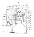
【選択図】図4
An automatic liquid ejection device capable of stabilizing the time from the start of a push-down operation of a push-down head of a container with a pump to the start of liquid ejection is provided.
If the lifting unit 50 having the head fitting frame 4 in which the press-down head 37 of the pump-equipped container 30 is fitted is moved up and down, and only the liquid is discharged from the discharge nozzle of the pump-equipped container 30 by pushing down the press-down head 37. In addition, the automatic liquid ejection device 1 having the head pressing mechanism 80 that also raises and returns the pressing head 37 that has been pressed down to the upper and lower upper limit positions.
[Selection] Figure 4

Description

本発明は、消毒液や洗浄液等の液体を収容する容器に押下ヘッドの押し下げ操作によって前記容器内の液体を吐出ノズルへ供給するポンプを装着したポンプ付き容器を筐体内に取り出し可能に格納し、検出領域に差し込まれたユーザー(利用者)の手指をセンサによって検出したときに、前記液体を吐出ノズルから吐出する吐出動作を自動で行う自動液吐出装置に関する。   The present invention stores a container with a pump in which a pump for supplying liquid in the container to a discharge nozzle by a push-down operation of a pressing head in a container for storing liquid such as disinfecting liquid or cleaning liquid is detachably stored in the housing. The present invention relates to an automatic liquid discharge apparatus that automatically performs a discharge operation of discharging the liquid from a discharge nozzle when a finger of a user (user) inserted into a detection region is detected by a sensor.

従来より、手指の消毒や洗浄等のために、ユーザー(利用者)の手指をセンサによって検出することにより、消毒液や洗浄液といった液体を吐出ノズルから自動的に吐出する自動液吐出装置が提供されている。この自動液吐出装置としては、消毒液や洗浄液等の液体を収容したボトル形の容器にその上方に突出する押下ヘッドを有するポンプを装着したポンプ付き容器(図14参照)を筐体内に格納したものがある。この自動液吐出装置は、ポンプ付き容器の押下ヘッドの側方から突出する吐出ノズル自体を装置の吐出ノズルとするものであり、センサがユーザーの手指を検出することで筐体内の押下機構が駆動してポンプ付き容器の押下ヘッドを自動的に押し下げ、容器内の液体を前記吐出ノズルから吐出する(例えば特許文献1)。   2. Description of the Related Art Conventionally, an automatic liquid discharge device that automatically discharges liquid such as disinfectant liquid and cleaning liquid from a discharge nozzle by detecting a user's (user's) finger with a sensor for disinfection and cleaning of fingers has been provided. ing. As this automatic liquid discharge device, a container with a pump (see FIG. 14) in which a pump having a push-down head projecting above a bottle-shaped container containing a liquid such as a disinfecting liquid or a cleaning liquid is stored in a housing. There is something. This automatic liquid discharge device uses the discharge nozzle itself that protrudes from the side of the press head of the container with the pump as the discharge nozzle of the device, and the press mechanism in the housing is driven by the sensor detecting the user's finger. Then, the pressing head of the container with the pump is automatically pushed down, and the liquid in the container is discharged from the discharge nozzle (for example, Patent Document 1).

図14は、上述の自動液吐出装置に用いられるポンプ付き容器100のポンプ110と、自動液吐出装置の押下機構の押下部材120との関係を説明する図である。なお、図14において、上側を上、下側を下として説明する。
前記ポンプ付き容器100のポンプ110は、ボトル形の容器101の上部開口部102に螺着したキャップ111を貫通して昇降可能に設けたステム112のキャップ111上に突出された上端に一体化された押下ヘッド114及び該押下ヘッド114からその側方に突出する吐出ノズル113が設けられたノズル付き押下レバー110Aを有する。
FIG. 14 is a diagram illustrating the relationship between the pump 110 of the pump-equipped container 100 used in the above-described automatic liquid discharging apparatus and the pressing member 120 of the pressing mechanism of the automatic liquid discharging apparatus. In FIG. 14, description will be made with the upper side as the upper side and the lower side as the lower side.
The pump 110 of the container 100 with the pump is integrated with an upper end protruding on the cap 111 of the stem 112 that can be moved up and down through the cap 111 screwed into the upper opening 102 of the bottle-shaped container 101. A pressing lever with nozzle 110A provided with a pressing head 114 and a discharge nozzle 113 projecting laterally from the pressing head 114.

ノズル付き押下レバー110Aは、ポンプ110に設けられた図示略のリターンスプリングによって上方へ弾性付勢されており、自動液吐出装置は、センサがユーザーの手指を検出したときに押下機構が、ポンプ付き容器100のポンプ110の押下ヘッド114上に載置状態に設けられた押下部材120を下降させて、ノズル付き押下レバー110Aをリターンスプリングの弾性付勢力に抗して押し下げる。ポンプ付き容器100は、ノズル付き押下レバー110Aの押し下げによって、ノズル付き押下レバー110Aに貫設された吐出用液流路119の吐出ノズル113先端に開口する吐出液流路119の片端の液出口119bから液体を吐出する。   The pressing lever with nozzle 110A is elastically biased upward by a return spring (not shown) provided in the pump 110, and the automatic liquid discharge device has a pressing mechanism with a pump when the sensor detects the user's finger. The pressing member 120 provided on the pressing head 114 of the pump 110 of the container 100 is lowered, and the pressing lever with nozzle 110A is pressed down against the elastic biasing force of the return spring. The pump-equipped container 100 has a liquid outlet 119b at one end of the discharge liquid channel 119 that opens at the tip of the discharge nozzle 113 of the discharge liquid channel 119 penetrating the press-down lever 110A with nozzle when the press-down lever 110A with nozzle is pressed down. To discharge liquid.

押下機構による押下部材120の下降(押し下げ)は、押下部材120が予め設定された下降限界位置に達したところで完了する。ノズル付き押下レバー110A及び押下部材120は、押下機構による押下部材120の押し下げ完了後に、ポンプ付き容器100のリターンスプリングの弾性付勢力によって押し上げられて押し下げ前の位置(初期位置)に復帰する。また、押し下げ完了後の押下部材120を、その上下動ストロークの上限位置への復帰を、押下機構に設けられたスプリングによって行い、ポンプ付き容器100のノズル付き押下レバーの上昇限界位置(リターンスプリングによる押し上げ限界位置)への復帰をポンプのリターンスプリングによって行う構成も提案されている。   The lowering (pressing down) of the pressing member 120 by the pressing mechanism is completed when the pressing member 120 reaches a preset lower limit position. The push-down lever 110A with nozzle and the push-down member 120 are pushed up by the elastic biasing force of the return spring of the container 100 with pump after the push-down member 120 is pushed down by the push-down mechanism, and return to the position before the push-down (initial position). In addition, the pressing member 120 after the completion of the pressing down is returned to the upper limit position of the vertical movement stroke by a spring provided in the pressing mechanism, and the rising limit position of the pressing lever with nozzle of the container 100 with pump (by the return spring). A configuration has also been proposed in which the return to the push-up limit position) is performed by a pump return spring.

自動液吐出装置は、押下部材120が、ポンプ110のノズル付き押下レバーの上昇限界位置(押し下げ前の初期位置)に対応して設定した初期位置(押し下げ前の位置)にある状態で、ユーザーの手指を検出していない手指検出用のセンサが前記手指を検出することで、押下部材120の押し下げによる液体吐出動作(ここではノズル付き押下レバー110A及び押下部材120の押し下げ開始から初期位置への復帰までを指す)を、予め設定した回数(1回又は複数回)だけ実行する。
自動液吐出装置は、液体吐出動作を行っていない状態において、ユーザーの手指を検出していない手指検出用のセンサが前記手指を検出したときに、液体吐出動作を実行する。液体動作中から動作完了後まで手指検出用センサが前記手指の検出を継続しているときは、設定回数の吐出動作の完了後に、手指検出用センサが手指を検出していない状態にしてから手指検出用センサが手指を検出することで、次回の吐出動作が実行される。
The automatic liquid discharge device is in a state where the pressing member 120 is in an initial position (position before pressing) set in correspondence with the rising limit position (initial position before pressing) of the pressing lever with nozzle of the pump 110. When the finger detection sensor that has not detected the finger detects the finger, a liquid discharge operation is performed by pressing the pressing member 120 (here, the pressing lever 110A with the nozzle and the pressing member 120 are returned to the initial positions from the start of pressing). Are executed a predetermined number of times (one or more times).
The automatic liquid ejection device performs a liquid ejection operation when a finger detection sensor that has not detected a user's finger detects the finger in a state where the liquid ejection operation is not performed. When the finger detection sensor continues to detect the finger from the liquid operation to the completion of the operation, the finger detection sensor is not detecting the finger after the set number of ejection operations are completed, and then the finger is detected. When the detection sensor detects the finger, the next discharge operation is executed.

特開2001−153036号公報JP 2001-153036 A

図14に例示した従来の自動液吐出装置は、押下部材120が押下ヘッド114の押し下げを開始してから液体吐出開始までの時間にばらつきがあるといった不満があった。
本発明者による検証の結果、押下部材120が押下ヘッド114を押し下げる際に、ステム112が斜め押しの状態となることがあり、この斜め押しの発生の有無が液体吐出開始時間のばらつきの原因になっている。
The conventional automatic liquid ejecting apparatus illustrated in FIG. 14 has been dissatisfied with variations in the time from when the pressing member 120 starts to press down the pressing head 114 until the liquid discharge starts.
As a result of verification by the present inventor, when the pressing member 120 pushes down the pressing head 114, the stem 112 may be in an obliquely pressed state, and the presence or absence of this oblique pressing causes the dispersion of the liquid discharge start time. It has become.

本発明は、上述の課題に鑑みて、ヘッド押下機構の押下ヘッドの押し下げ動作開始から液体吐出開始までの時間を安定化することができる自動液吐出装置の提供を目的とする。   In view of the above-described problems, an object of the present invention is to provide an automatic liquid ejecting apparatus that can stabilize the time from the start of the pressing operation of the pressing head of the head pressing mechanism to the start of liquid discharge.

図14に例示した従来の自動液吐出装置について、本発明者による検証の結果、ステム112の斜め押しは、押下部材120が押下ヘッド114を上昇限界位置から押し下げる際に、押下ヘッド114が押下部材120に対して滑って位置ずれを生じることで発生している。
ポンプ付き容器100の構成部材はプラスチック製であることが一般的である。一方、自動液吐出装置の押下部材120は、ポンプ付き容器100のポンプ110の種々の押下ヘッド114形状に対応して押し下げを可能にするために、ステム112の軸線に垂直に延在する板状に形成されていることが一般的である。押下ヘッド114の押下部材120に対する滑りによる位置ずれは、押下部材120が押下ヘッド114を上昇限界位置から押し下げる際に、プラスチック製のステム112に若干の弾性変形(撓み変形)が生じることに起因する。押下ヘッド114に押下部材120に対する位置ずれが生じると、ステム112の撓み変形が大きくなり、その結果、ステム112が斜め押しの状態となる。
As a result of verification by the inventor of the conventional automatic liquid ejection device illustrated in FIG. 14, as a result of the verification by the present inventor, when the pressing member 120 pushes the pressing head 114 down from the upper limit position, the pressing head 114 presses the pressing member 114. It is generated by slipping with respect to 120 and causing positional deviation.
The constituent members of the pump-equipped container 100 are generally made of plastic. On the other hand, the pressing member 120 of the automatic liquid discharge device is a plate-like shape extending perpendicularly to the axis of the stem 112 in order to enable pressing down in accordance with various pressing head 114 shapes of the pump 110 of the pump-equipped container 100. Generally, it is formed. The displacement due to the sliding of the pressing head 114 with respect to the pressing member 120 is caused by a slight elastic deformation (deflection deformation) in the plastic stem 112 when the pressing member 120 presses the pressing head 114 from the upper limit position. . When the pressing head 114 is displaced with respect to the pressing member 120, the bending deformation of the stem 112 is increased, and as a result, the stem 112 is in an obliquely pressed state.

ステム112が斜め押しの状態となると、ステム112に斜め押しが生じていない場合に比べて、押下機構の押下ヘッドの押し下げ動作開始から液体吐出開始までの時間が長くなる。このことは、吐出ノズル113からの液体吐出前に、ユーザーが吐出ノズル113先端付近に差し出していた手を引っ込めてしまい、その後に吐出ノズル113から吐出された液体が無駄になる、といった不都合を誘発する。手指検出用のセンサがユーザーの手指を検出したときに2回以上の吐出動作を連続して実行する設定の場合には、吐出ノズル113から複数回行われる液体吐出の時間間隔が長くなると、ユーザーが設定数の吐出動作が完了したものと誤認して、設定数の吐出動作の完了前に、ユーザーが吐出ノズル113先端付近に差し出していた手を引っ込めてしまうことが生じ得る。   When the stem 112 is in the diagonally pressed state, the time from the start of the pressing-down operation of the pressing head of the pressing mechanism to the start of liquid discharge becomes longer than when the stem 112 is not diagonally pressed. This induces inconvenience that the user withdraws the hand that has been put out near the tip of the discharge nozzle 113 before the liquid is discharged from the discharge nozzle 113, and the liquid discharged from the discharge nozzle 113 is wasted after that. To do. When the finger detection sensor detects a user's finger, the setting is such that two or more discharge operations are continuously performed. However, it may be misunderstood that the set number of discharge operations have been completed, and the user may withdraw his hand that has been put out near the tip of the discharge nozzle 113 before the set number of discharge operations are completed.

また、押下部材114に対する滑りによるステム112の変形が大きい場合は、押し下げ完了によって下方への押圧力が解除された後もステム112が真っ直ぐの状態に直ちに復元せず、ステム112の若干の曲げ癖によって、押し下げ後のステム112の上昇時のキャップ111に対する摺動抵抗が大きくなり、ステム112の押し下げ前の元の位置への上昇が遅れることがある。これが、次の吐出動作の遅れの原因となる。また、ステム112の曲げ癖は、次の吐出動作の際の、押下部材120に対する押下ヘッド114の滑り、それによる斜め押しの原因になる。   Further, when the stem 112 is greatly deformed due to the sliding with respect to the pressing member 114, the stem 112 is not immediately restored to the straight state even after the downward pressing force is released by the completion of the pressing, and the stem 112 is slightly bent. As a result, the sliding resistance against the cap 111 when the stem 112 is raised after the push-down increases, and the rise of the stem 112 to the original position before the push-down may be delayed. This causes a delay in the next discharge operation. Further, the bending wrinkles of the stem 112 cause the pressing head 114 to slide with respect to the pressing member 120 during the next discharge operation, and thereby cause oblique pressing.

押下ヘッド114としては、平坦な上面を有する円板状のもの(図14参照)以外に、ドーム形の上面を有する板状のものや、押下ヘッド114全体が球状のもの等のように板状の押下部材120との接触部分が小さいものもある。このような接触部分が小さい押下ヘッドは、押下部材120による押し下げ時に押下部材120に対して滑りによる位置ずれを生じやすく、位置ずれに起因した上述の斜め押しの発生頻度が高くなる。   As the pressing head 114, in addition to a disk-shaped one having a flat upper surface (see FIG. 14), a plate-shaped one having a dome-shaped upper surface, or a plate shape such as a spherical one having a whole pressing head 114 is used. Some of the contact portions with the pressing member 120 are small. Such a pressing head having a small contact portion is likely to be displaced due to slipping with respect to the pressing member 120 when pressed by the pressing member 120, and the frequency of occurrence of the above-described oblique pressing due to the positional shift is increased.

本発明は、上記知見に基づき、ヘッド押下機構の押下ヘッドの押し下げ動作開始から液体吐出開始までの時間を安定化するために以下の構成を提供する。
第1の発明は、液体を収容する容器に押下ヘッドの押し下げ操作によって前記液体を吐出ノズルへ供給して吐出させるポンプを装着したポンプ付き容器を取り出し可能に格納する筐体に、前記吐出ノズルから液体が吐出される吐出領域あるいはその近傍を含んで設定した検出領域に差し込まれたユーザーの手指を検出するセンサと、該センサが前記手指を検出したときに前記ポンプの押下ヘッドを押し下げるヘッド押下機構とが設けられ、前記ヘッド押下機構は、前記ポンプのポンプケースに昇降可能に挿入されその上方に突出するステムの上端に該ステムの軸線に垂直の板状に形成された前記押下ヘッドが脱着可能に嵌め込まれることで該押下ヘッドを上下から挟持する四角枠状のヘッド嵌合枠が、前記筐体に上下方向に延在配置された昇降案内部材に案内されて上下方向に移動する昇降ベースに一体化された昇降ユニットと、この昇降ユニットを予め設定した昇降ストロークを以て上下動させる昇降用駆動機構とを有することを特徴とする自動液吐出装置を提供する。
第2の発明は、前記ヘッド嵌合枠の昇降ストロークによるポンプ付き容器のポンプの押下ヘッドの昇降上限位置が、前記ポンプ付き容器のポンプの構造上の押下ヘッドの上昇限界位置よりも下方に位置することを特徴とする第1の発明の自動液吐出装置を提供する。
第3の発明は、前記昇降用駆動機構はモータを駆動源とするギアユニットであることを特徴とする第1または第2の発明の自動液吐出装置を提供する。
Based on the above knowledge, the present invention provides the following configuration in order to stabilize the time from the start of the pressing operation of the pressing head of the head pressing mechanism to the start of liquid ejection.
According to a first aspect of the present invention, there is provided a housing for detachably storing a pump-equipped container equipped with a pump for supplying and discharging the liquid to the discharge nozzle by a push-down operation of a pressing head to a container for storing the liquid. A sensor for detecting a finger of a user inserted in a detection area set including or near a discharge area where liquid is discharged, and a head pressing mechanism for pressing down a pressing head of the pump when the sensor detects the finger The head pressing mechanism is inserted into the pump case of the pump so as to be movable up and down, and the pressing head formed in a plate shape perpendicular to the axis of the stem is detachable at the upper end of the stem protruding above A rectangular frame-shaped head fitting frame that sandwiches the pressing head from above and below by being fitted into the housing is a vertically extending arrangement arranged on the casing. An automatic liquid discharge comprising an elevating unit integrated with an elevating base guided by a guide member and moving up and down, and an elevating drive mechanism for moving the elevating unit up and down with a preset elevating stroke Providing equipment.
According to a second aspect of the present invention, the upper / lower upper limit position of the press-down head of the pump of the pump-equipped container due to the up-and-down stroke of the head fitting frame is positioned below the upper limit position of the press-down head on the pump structure of the pump-equipped container. An automatic liquid discharge apparatus according to a first aspect of the invention is provided.
A third invention provides the automatic liquid ejection device according to the first or second invention, wherein the elevating drive mechanism is a gear unit using a motor as a drive source.

本発明によれば、ポンプ付き容器の押下ヘッドを押し下げるヘッド嵌合枠が四角枠状となっており、押下ヘッドを上下から挟持した状態となるため、ヘッド嵌合枠に対する押下ヘッドの位置ずれを生じることがない。このため、押下ヘッドの位置ずれに起因したステムの斜め押しを防ぐことができ、ヘッド押下機構の押下ヘッドの押し下げ動作開始から液体吐出開始までの時間を安定化することができる。   According to the present invention, the head fitting frame that pushes down the pressing head of the pump-equipped container has a square frame shape, and the pressing head is sandwiched from above and below. It does not occur. Therefore, it is possible to prevent the stem from being pushed obliquely due to the positional deviation of the pressing head, and it is possible to stabilize the time from the start of the pressing operation of the pressing head of the head pressing mechanism to the start of liquid ejection.

また、本発明に係る自動液吐出装置のヘッド押下機構は、ヘッド嵌合枠が設けられている昇降ユニットを上下動させる昇降用駆動機構を有しており、昇降ユニットの押し下げのみならず、押し下げの完了した昇降ユニットの昇降上限位置への復帰をも行う。したがって、この自動液吐出装置は、ヘッド押下機構の駆動によって、押し下げ完了後の昇降ユニットを上昇させることで押下ヘッドを昇降ユニットとともに押し下げ前の位置に確実に復帰させることができる。また、ヘッド押下機構の駆動によって、押し下げ完了後の昇降ユニットを上昇させることで、昇降ユニットのヘッド嵌合枠に嵌合状態の押下ヘッドも昇降ユニットとともに押し下げ前の位置に復帰させる構成は、押し下げ完了後の押下ヘッドが押し下げ前の位置に復帰するまでに要する時間が安定する。このことも、ヘッド押下機構の押下ヘッドの押し下げ動作開始から液体吐出開始までの時間の安定化に有効に寄与する。
さらに、この構成であれば、例えば比較的粘度が高い液体をポンプ付き容器から吐出した場合でも、押し下げを完了した昇降ユニットの上昇によって押下ヘッドを昇降ユニットとともに押し下げ前の位置に確実に復帰させることができるため、押下ヘッドの上昇の遅れによって次回吐出動作までの待機時間が長くなるといった不都合の発生を防ぐことができる。
In addition, the head pressing mechanism of the automatic liquid ejection device according to the present invention has a lifting drive mechanism that moves the lifting unit provided with the head fitting frame up and down. The lifting / lowering unit that has been completed is also returned to the lifting / lowering upper limit position. Therefore, this automatic liquid discharge apparatus can reliably return the pressing head together with the lifting unit to the position before the pressing by raising the lifting unit after completion of the pressing by driving the head pressing mechanism. In addition, the configuration in which the push-down head fitted in the head fitting frame of the lift unit is returned to the position before being pushed down together with the lift unit by raising the lift unit after the push-down is completed by driving the head push-down mechanism is pushed down. The time required for the pressing head after completion to return to the position before the pressing down is stabilized. This also contributes to stabilization of the time from the start of the pressing operation of the pressing head of the head pressing mechanism to the start of liquid ejection.
Furthermore, with this configuration, for example, even when a liquid having a relatively high viscosity is discharged from a container with a pump, the pressing head is reliably returned to the position before being pushed down together with the lifting unit by the lifting of the lifting unit that has been pushed down. Therefore, it is possible to prevent the occurrence of inconvenience that the waiting time until the next discharge operation becomes longer due to the delay of the raising of the pressing head.

本発明の一実施形態の自動液吐出装置を示す全体斜視図である。1 is an overall perspective view showing an automatic liquid discharge apparatus according to an embodiment of the present invention. 図1の自動液吐出装置の液受けトレーを前カバーに対して開いて使用状態とした状態を示す全体斜視図である。FIG. 2 is an overall perspective view showing a state in which a liquid receiving tray of the automatic liquid discharging apparatus of FIG. 図1の自動液吐出装置における筐体の前カバーを取り外した状態を示す斜視図である。It is a perspective view which shows the state which removed the front cover of the housing | casing in the automatic liquid discharge apparatus of FIG. 図1の自動液吐出装置における昇降ユニット付近を示す正面図である。It is a front view which shows the raising / lowering unit vicinity in the automatic liquid discharge apparatus of FIG. 図1の自動液吐出装置における昇降ユニット付近を示す部分破断側面図である。It is a partially broken side view which shows the raising / lowering unit vicinity in the automatic liquid discharge apparatus of FIG. 図1の自動液吐出装置における昇降ユニット付近を示す部分破断平面図である。FIG. 2 is a partially broken plan view showing the vicinity of an elevating unit in the automatic liquid ejection device of FIG. 1. 図1の自動液吐出装置における昇降ユニット及び該昇降ユニットのヘッド嵌合枠に嵌め込まれた押下ヘッドが、昇降用駆動機構による昇降ストロークの昇降上限位置にある状態を示す正面図である。It is a front view which shows the state which the raising / lowering unit in the automatic liquid discharge apparatus of FIG. 1 and the pressing head fitted in the head fitting frame of this raising / lowering unit exist in the raising / lowering upper limit position of the raising / lowering stroke by the raising / lowering drive mechanism. 昇降ユニット及び押下ヘッドが図7の昇降上限位置から該昇降上限位置と昇降下限位置との間の中間位置に下降された状態を示す正面図である。It is a front view which shows the state which the raising / lowering unit and the pressing-down head were lowered | hung from the raising / lowering upper limit position of FIG. 7 to the intermediate position between this raising / lowering upper limit position and raising / lowering lower limit position. 昇降ユニット及び押下ヘッドが昇降下限位置にある状態を示す正面図である。It is a front view which shows the state which has a raising / lowering unit and a pressing head in a raising / lowering lower limit position. 昇降ユニット及び押下ヘッドが図9の昇降下限位置から該昇降下限位置と昇降上限位置との間の中間位置に上昇された状態を示す正面図である。FIG. 10 is a front view showing a state where the lifting unit and the pressing head are raised from the lower limit position of FIG. 9 to an intermediate position between the lower limit position and the upper limit position. 図1の自動液吐出装置に用いられるポンプ付き容器の一例を示す側面図である。It is a side view which shows an example of the container with a pump used for the automatic liquid discharge apparatus of FIG. 図1の自動液吐出装置に用いられるポンプ付き容器の他の例を示す側面図である。It is a side view which shows the other example of the container with a pump used for the automatic liquid discharge apparatus of FIG. (a)〜(c)は、図1の自動液吐出装置に用いられるポンプ付き容器の押下ヘッドの別態様を示す図である。(A)-(c) is a figure which shows another aspect of the pressing-down head of the container with a pump used for the automatic liquid discharge apparatus of FIG. 従来の自動液吐出装置の押下部材とポンプ付き容器の押下ヘッドとの関係を示す側面図である。It is a side view which shows the relationship between the pressing member of the conventional automatic liquid discharge apparatus, and the pressing head of the container with a pump.

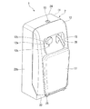
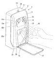
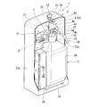
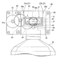
以下、本発明を図示する実施形態により具体的に説明する。図1〜図11は本発明の一実施形態の自動液吐出装置1を示し、図1は全体斜視図、図2は使用状態の斜視図、図3は内部を示す斜視図である。
なお、図1〜図5、図7〜図13(a)〜(c)において、上側を上、下側を下として説明する。また、図4、図6〜図10、図12、図13(a)〜(c)において、左右を左右(左側を左、右側を右)として説明する。
Hereinafter, the present invention will be described in detail with reference to the illustrated embodiments. 1 to 11 show an automatic liquid discharge apparatus 1 according to an embodiment of the present invention. FIG. 1 is an overall perspective view, FIG. 2 is a perspective view in use, and FIG. 3 is a perspective view showing the inside.
In FIG. 1 to FIG. 5 and FIG. 7 to FIG. 13A to FIG. Also, in FIGS. 4, 6 to 10, 12, and 13 (a) to 13 (c), left and right are described as left and right (left is left and right is right).

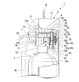
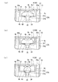
図3に示すように、自動液吐出装置1は、略直方体のボックス状となっている筐体2の内部に、消毒液、洗浄液といった液体を収容するポンプ付き容器30を出し入れ可能に格納している。また、この自動液吐出装置1は、図4に示すように、筐体2内に、前記ポンプ付き容器30の容器31からその上方に突出されたステム34上端の押下ヘッド37を押し下げて、ポンプ付き容器30内の液体を押下ヘッド37からその側方に突出する吐出ノズル35先端から吐出させるヘッド押下機構80を有する。図1、図2に示すように、ポンプ付き容器30の前記吐出ノズル35は、筐体2に形成されたノズル突出用長孔15を介して筐体2外側に突出されている。   As shown in FIG. 3, the automatic liquid discharge apparatus 1 stores a pump-equipped container 30 that contains liquid such as disinfectant liquid and cleaning liquid in a substantially rectangular box-shaped housing 2 so that it can be taken in and out. Yes. In addition, as shown in FIG. 4, the automatic liquid discharge device 1 pushes down the pressing head 37 at the upper end of the stem 34 protruding upward from the container 31 of the pump-equipped container 30 into the casing 2 so that the pump A head pressing mechanism 80 is provided for discharging the liquid in the attached container 30 from the tip of the discharge nozzle 35 protruding from the pressing head 37 to the side thereof. As shown in FIGS. 1 and 2, the discharge nozzle 35 of the pump-equipped container 30 protrudes to the outside of the housing 2 through a nozzle protruding elongated hole 15 formed in the housing 2.

また、この自動液吐出装置1は、吐出ノズル35から液体が吐出される吐出領域(吐出ノズル35先端部の延長上に位置する領域)あるいはその近傍を含んで設定した検出領域に差し込まれたユーザーの手指10を検出するセンサ7(図3、図5参照)を有する。そして、この自動液吐出装置1は、センサ7がユーザーの手指10を検出することで、制御部21(ここでは後述の制御基板)によって駆動制御される前記ヘッド押下機構80が、ポンプ付き容器30の前記押下ヘッド37を押し下げ、ポンプ付き容器30内の消毒液、洗浄液といった液体を吐出ノズル35先端から吐出させる。
なお、この自動液吐出装置1のヘッド押下機構80は、後述のように、ポンプ付き容器30の押下ヘッド37を押し下げのみならず、押下ヘッド37を押し下げた後に、次の押し下げ動作に備えるために、該押下ヘッド37を上昇させ、押し下げ前の初期位置(昇降上限位置)への復帰をも行うものである。
In addition, the automatic liquid ejection apparatus 1 is configured such that a user inserted into a discharge area (area located on the extension of the front end of the discharge nozzle 35) where the liquid is discharged from the discharge nozzle 35 or a detection area set in the vicinity thereof. The sensor 7 (refer FIG. 3, FIG. 5) which detects the finger 10 of this is included. In the automatic liquid ejection device 1, the sensor 7 detects the user's finger 10, so that the head pressing mechanism 80 that is driven and controlled by the control unit 21 (a control board described later) is provided in the container 30 with the pump. The pressing head 37 is pushed down, and liquid such as disinfectant liquid and cleaning liquid in the pump-equipped container 30 is discharged from the tip of the discharge nozzle 35.
As will be described later, the head pressing mechanism 80 of the automatic liquid ejecting apparatus 1 not only depresses the pressing head 37 of the pump-equipped container 30 but also prepares for the next pressing operation after the pressing head 37 is pressed down. The pressing head 37 is raised to return to the initial position (up / down upper limit position) before being pressed down.

図1〜図3に示すように、筐体2は、底板22上に平面視コ字形の側壁部23が立設され該側壁部23上に天板部24を有する容器状の筐体本体11と、筐体本体11の前面側の開口部11aに脱着可能に設けられ前記開口部11aを開閉可能となっている前カバー12とによって構成されている。筐体本体11及び前カバー12はプラスチック製の部材である。
筐体本体11の天板部24にはキー孔13が設けられており、キー孔13にキー14(図3参照)を差し込んで回転操作することにより前カバー12の閉じ状態のロックとロック解除とを切り換えることができる。筐体本体11から前カバー12を取り外し、筐体本体11の前面側の開口部11aを開放すると、ポンプ付き容器30の交換作業を行える。
As shown in FIGS. 1 to 3, the housing 2 has a container-like housing body 11 having a U-shaped side wall portion 23 standing on a bottom plate 22 and having a top plate portion 24 on the side wall portion 23. And a front cover 12 that is detachably provided in the opening 11a on the front side of the housing body 11 and that can open and close the opening 11a. The housing body 11 and the front cover 12 are plastic members.
The top plate portion 24 of the housing body 11 is provided with a key hole 13, and the front cover 12 is locked and unlocked by inserting the key 14 (see FIG. 3) into the key hole 13 and rotating it. And can be switched. When the front cover 12 is removed from the housing body 11 and the opening 11a on the front surface side of the housing body 11 is opened, the replacement work of the container 30 with the pump can be performed.

前カバー12のノズル突出用長孔15は、前カバー12に上下方向に延在形成されている。吐出ノズル35は、自動液吐出装置1のヘッド押下機構80によるポンプ付き容器30の押下ヘッド37の昇降に伴い、ノズル突出用長孔15を貫通した状態のまま、前記押下ヘッド37と一体的に昇降する。
ノズル突出用長孔15は、ヘッド押下機構80による押下ヘッド37の昇降に伴う吐出ノズル35の押下ヘッド37との一体的な昇降を可能とするために、前カバー12における上下方向の形成範囲を、ヘッド押下機構80による押下ヘッド37の昇降に伴う吐出ノズル35の上下方向の可動範囲よりも若干大きく確保してある。
The long hole 15 for protruding the nozzle of the front cover 12 is formed in the front cover 12 so as to extend in the vertical direction. The discharge nozzle 35 is integrated with the pressing head 37 while passing through the nozzle protruding elongated hole 15 as the pressing head 37 of the pump-equipped container 30 is moved up and down by the head pressing mechanism 80 of the automatic liquid discharging apparatus 1. Go up and down.
The long hole 15 for protruding the nozzle has a vertical formation range in the front cover 12 in order to allow the discharge nozzle 35 to move up and down integrally with the pressing head 37 when the pressing head 37 is moved up and down by the head pressing mechanism 80. Further, it is ensured that it is slightly larger than the movable range in the vertical direction of the discharge nozzle 35 as the pressing head 37 is moved up and down by the head pressing mechanism 80.

図2に示すように、筐体2の前カバー12の前面部分における下部には透明パネル部16が設けられており、透明パネル部16を通じて筐体2の内部の透視が可能となっている。従って、ポンプ付き容器30内の液体の残量を透明パネル部16を通じて確認することができる。
なお、図示例の筐体2における、前カバー12の透明パネル部16及び後述のセンサカバー部12a以外の部分と、筐体本体11とは遮光性を有している。
As shown in FIG. 2, a transparent panel portion 16 is provided at the lower part of the front surface portion of the front cover 12 of the housing 2, and the inside of the housing 2 can be seen through the transparent panel portion 16. Therefore, the remaining amount of liquid in the pump-equipped container 30 can be confirmed through the transparent panel portion 16.
In the case 2 shown in the drawing, the portion other than the transparent panel portion 16 and the sensor cover portion 12a described later of the front cover 12 and the case main body 11 have light shielding properties.

前カバー12には、皿形の液受けトレー17が回動可能に取り付けられている。この液受けトレー17は、その外周部の一部が、筐体本体11の底板22にその前面側のヒンジ部25を介して底板22前面と底板22上面との境界に沿って延在する回転軸線を以て回転可能に枢着され、前記ヒンジ部25から延出されている。この液受けトレー17は、前記ヒンジ部25を中心とする回動によって、筐体本体11に装着状態の前カバー12にその外面側から重ねた閉じ状態(図1参照)と、筐体2から前側に突出する開状態(図2参照)とを自在に切り換えることができる。液受けトレー17は、図2に例示した開状態にすることで、前カバー12の前記ノズル突出用長孔15から筐体2前側に突出された吐出ノズル35の下方に配置され、前記吐出ノズル35から吐出された液体を受け止める位置となるため、液体がテーブル面や床面に落下することを防止することができる。   A dish-shaped liquid receiving tray 17 is rotatably attached to the front cover 12. The liquid receiving tray 17 has a part of its outer periphery that extends to the bottom plate 22 of the housing body 11 along the boundary between the front surface of the bottom plate 22 and the top surface of the bottom plate 22 via the hinge portion 25 on the front surface side. It is pivotally attached to an axis and is extended from the hinge portion 25. The liquid receiving tray 17 is pivoted around the hinge portion 25 to close the front cover 12 mounted on the housing body 11 from the outer surface side (see FIG. 1), and from the housing 2. The open state (see FIG. 2) protruding forward can be freely switched. When the liquid receiving tray 17 is in the open state illustrated in FIG. 2, the liquid receiving tray 17 is disposed below the discharge nozzle 35 protruding to the front side of the housing 2 from the nozzle protruding long hole 15 of the front cover 12. Since it becomes a position which receives the liquid discharged from 35, it can prevent that a liquid falls on a table surface or a floor surface.

なお、この実施形態の液受けトレー17は遮光性部材である。図1に示すように、閉じ状態にした液受けトレー17は、前カバー12の透明パネル部16を覆って、筐体2内のポンプ付き容器30への太陽光や紫外光等の外光の照射を防ぐことができる。但し、液受けトレー17は、少なくとも吐出ノズル35から吐出された液体を受け止める機能を有していれば良く、必ずしも遮光性部材である必要は無い。   In this embodiment, the liquid receiving tray 17 is a light shielding member. As shown in FIG. 1, the liquid receiving tray 17 in the closed state covers the transparent panel portion 16 of the front cover 12, and external light such as sunlight and ultraviolet light to the container 30 with a pump in the housing 2. Irradiation can be prevented. However, the liquid receiving tray 17 only needs to have a function of receiving at least the liquid discharged from the discharge nozzle 35, and is not necessarily a light shielding member.

図3に例示したセンサ7は、ユーザーの手指からの赤外線を検出する赤外線センサである。この赤外線センサ(センサ7)は、筐体2の内部に設けられており、図1、図2に示すように前カバー12に設けられた赤外線透過性のセンサカバー部12aを介して、ユーザーの手指からの赤外線を検出する。センサカバー部12aは、遮光性の前カバー12の前面側に突出するキャップ状に形成されており、前カバー12を筐体本体11に装着した状態においてその内側にセンサ7を収納する。   The sensor 7 illustrated in FIG. 3 is an infrared sensor that detects infrared rays from the user's fingers. This infrared sensor (sensor 7) is provided inside the housing 2, and as shown in FIGS. 1 and 2, the infrared sensor (12) provided on the front cover 12 is connected to the user through the infrared transparent sensor cover portion 12a. Detect infrared rays from fingers. The sensor cover portion 12 a is formed in a cap shape that protrudes to the front side of the light-shielding front cover 12, and houses the sensor 7 inside the front cover 12 in a state where the front cover 12 is attached to the housing body 11.

図3、図5に示すように、赤外線センサ(センサ7)は、具体的には、筐体本体11に取り付けて筐体2内側上部に設けられた制御基板21に実装されている。但し、センサ7としては、赤外線センサに限定されず、吐出ノズル35から液体が吐出される吐出領域あるいはその近傍を含んで設定した検出領域に差し込まれたユーザーの手指10を検出可能なものであれば良く、また、その設置位置にも限定は無い。また、センサ7としては、センサカバー部12aを介してユーザーの手指からの赤外線を検出する形態に限定されず、ユーザーの手指からの赤外線をセンサカバー部12aを介さずに直接受光して検出する形態としても良い。   As shown in FIGS. 3 and 5, the infrared sensor (sensor 7) is specifically mounted on the control board 21 that is attached to the housing body 11 and provided on the inside upper portion of the housing 2. However, the sensor 7 is not limited to the infrared sensor, and can detect the user's finger 10 inserted into the detection region set including or near the discharge region where the liquid is discharged from the discharge nozzle 35. The installation position is not limited. Further, the sensor 7 is not limited to a mode in which infrared rays from the user's fingers are detected via the sensor cover portion 12a, and the infrared rays from the user's fingers are directly received and detected without passing through the sensor cover portion 12a. It is good also as a form.

なお、図示例のセンサカバー部12aは、前カバー12に形成された開口部12c(図1、図2参照)に赤外線透過性のキャップ状部材を内挿して、前カバー12にその前面側に突出状態に取り付けたものであるが、これに限定されない。例えば、予め制御基板21に固定してセンサ7を収納したキャップ状のセンサカバー部12aが、筐体本体11に対する前カバー12の着脱によって前カバー12に開口されている開口部12cに挿脱される構成も採用可能である。   The sensor cover 12a in the illustrated example has an infrared transmissive cap-like member inserted in an opening 12c (see FIGS. 1 and 2) formed in the front cover 12, and the front cover 12 has a front side thereof. Although attached to the protruding state, it is not limited to this. For example, a cap-shaped sensor cover portion 12 a that is previously fixed to the control board 21 and accommodates the sensor 7 is inserted into and removed from the opening portion 12 c that is opened in the front cover 12 when the front cover 12 is attached to or detached from the housing body 11. It is also possible to adopt a configuration.

図3に示すように、筐体2の筐体本体11の内部にはヘッド押下機構80(具体的には、図4等に示す後述の昇降用駆動機構60のモータ61)に電力を供給するバッテリユニット20が格納されている。制御部21(制御基板)は、バッテリユニット20の上側に配置されている。   As shown in FIG. 3, power is supplied to the inside of the casing body 11 of the casing 2 to a head pressing mechanism 80 (specifically, a motor 61 of an elevating drive mechanism 60 described later shown in FIG. 4). The battery unit 20 is stored. The control unit 21 (control board) is arranged on the upper side of the battery unit 20.

ヘッド押下機構80は、モータ61(電動モータ)を駆動源とする昇降用駆動機構60の駆動によって、ポンプ付き容器30の押下ヘッド37を嵌め込むことができるヘッド嵌合枠4を有する昇降ユニット50を昇降させて、昇降ユニット50とともにヘッド嵌合枠4に嵌め込まれた前記押下ヘッド37を昇降させる。制御部21は前記昇降用駆動機構60のモータ61の駆動を制御することにより、ヘッド押下機構80によるポンプ付き容器30の押下ヘッド37の昇降動作、すなわち、昇降用駆動機構60による昇降ユニット50のヘッド嵌合枠4の昇降動作を制御する。   The head pressing mechanism 80 is a lifting unit 50 having a head fitting frame 4 into which the pressing head 37 of the container 30 with a pump can be fitted by driving the lifting drive mechanism 60 using a motor 61 (electric motor) as a drive source. Is moved up and down to raise and lower the pressing head 37 fitted in the head fitting frame 4 together with the lifting unit 50. The control unit 21 controls the driving of the motor 61 of the lifting drive mechanism 60, so that the lifting operation of the pressing head 37 of the pump-equipped container 30 by the head pressing mechanism 80, that is, the lifting unit 50 by the lifting drive mechanism 60 is performed. The raising / lowering operation of the head fitting frame 4 is controlled.

図3に示すように、この自動液吐出装置1は、制御基板21に設けられている制御回路(電気回路)の回路電圧が予め設定した閾値以上であるか否かを表示するためのパワーモニタランプ8を有している。このパワーモニタランプ8としては、例えば制御基板21の回路電圧が予め設定した閾値以上であるときに点灯し、前記回路電圧が前記閾値よりも低いときに消灯するものや、回路電圧が前記閾値以上の状態から前記閾値よりも低くなったときに発光色が変化するもの等を用いることができる。
図示例の自動液吐出装置1において、パワーモニタランプ8は、前記制御基板21に実装して、前記前カバー12に設けられた出射窓12bに臨む位置に設けられており、点灯時の出射光を前記出射窓12bから筐体2前側へ出射できる。但し、パワーモニタランプ8の設置位置は、図示例に限定されず、適宜変更可能である。
As shown in FIG. 3, the automatic liquid ejection apparatus 1 is a power monitor for displaying whether or not the circuit voltage of a control circuit (electric circuit) provided on the control board 21 is equal to or higher than a preset threshold value. A lamp 8 is provided. For example, the power monitor lamp 8 is turned on when the circuit voltage of the control board 21 is equal to or higher than a preset threshold, and is turned off when the circuit voltage is lower than the threshold, or the circuit voltage is higher than the threshold. In this state, it is possible to use one whose emission color changes when it becomes lower than the threshold value.
In the automatic liquid discharge apparatus 1 shown in the drawing, the power monitor lamp 8 is mounted on the control board 21 and is provided at a position facing the emission window 12b provided in the front cover 12, and the emitted light at the time of lighting is provided. Can be emitted to the front side of the housing 2 from the emission window 12b. However, the installation position of the power monitor lamp 8 is not limited to the illustrated example, and can be changed as appropriate.

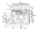
図3、図6に示すように、筐体本体11の側壁部23は、背板部23aとその両側の側板部23b、23cとによって平面視コ字形に形成されている。図3に示すように、バッテリユニット20は、側壁部23の一対の側板部23b、23cの一方(図3において符号23bの側板部23b)に取り付けられている。バッテリユニット20と該バッテリユニット20を取り付けた側板部23bとは反対側の側板部23cとの間には、ポンプ付き容器30の容器31を収納するための空間(容器収納空間)が確保されている。ポンプ付き容器30は、前記容器収納空間に収納した容器31を底板22上に載置し、容器31上方の押下ヘッド37をヘッド押下機構80の昇降ユニット50のヘッド嵌合枠4に脱着可能に嵌め込んで筐体本体11内に格納される。   As shown in FIGS. 3 and 6, the side wall portion 23 of the housing body 11 is formed in a U shape in plan view by a back plate portion 23 a and side plate portions 23 b and 23 c on both sides thereof. As illustrated in FIG. 3, the battery unit 20 is attached to one of the pair of side plate portions 23 b and 23 c of the side wall portion 23 (the side plate portion 23 b of reference numeral 23 b in FIG. 3). A space (container storage space) for storing the container 31 of the pump-equipped container 30 is secured between the battery unit 20 and the side plate part 23c opposite to the side plate part 23b to which the battery unit 20 is attached. Yes. In the container 30 with a pump, the container 31 stored in the container storage space is placed on the bottom plate 22, and the pressing head 37 above the container 31 is detachable from the head fitting frame 4 of the lifting unit 50 of the head pressing mechanism 80. It is fitted and stored in the housing body 11.

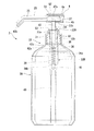
図11は、この実施形態の自動液吐出装置1のポンプ付き容器30を示す。ポンプ付き容器30は消毒液や洗浄液といった液体を収容する容器31と、容器31に装着されたポンプ32とを有している。
ポンプ32は、容器31上端の口部31a外周に螺着して着脱可能に取り付けられるキャップ33に、筒状のポンプケース36、前記キャップ33を貫通してその中心軸線に沿って移動するステム34等を設けたキャップ一体型のポンプである。
図11に示すポンプ付き容器30において前記ポンプ32は、容器31上端の口部31a外周に螺着して取り付けられたキャップ33と、キャップ33を上下方向に貫通して昇降可能に設けられたステム34の上端に押下ヘッド37及び吐出ノズル35を一体的に設けたノズル付き押下レバー32Aとを有している。また、このポンプ32は、前記キャップ33に連結して容器31内に挿入された筒状のポンプケース36と、前記キャップ33から下方に延出するポンプケース36の下端部から垂下する吸い上げ管40とを有している。吸い上げ管40は、前記ポンプケース36とともに容器31内に挿入され、その下端部が容器31底部に到達されている。
FIG. 11 shows a container 30 with a pump of the automatic liquid discharge apparatus 1 of this embodiment. The pump-equipped container 30 includes a container 31 for storing a liquid such as a disinfecting liquid or a cleaning liquid, and a pump 32 attached to the container 31.
The pump 32 has a cylindrical pump case 36 and a stem 34 that moves along the central axis thereof through a cap 33 that is detachably attached to the outer periphery of the mouth 31 a at the upper end of the container 31. This is a cap-integrated pump provided with the like.
In the container 30 with a pump shown in FIG. 11, the pump 32 includes a cap 33 that is screwed onto the outer periphery of the mouth 31a at the upper end of the container 31, and a stem that is vertically movable through the cap 33. 34, a press-down lever 32A with a nozzle integrally provided with a press-down head 37 and a discharge nozzle 35 is provided. The pump 32 includes a cylindrical pump case 36 that is connected to the cap 33 and inserted into the container 31, and a suction pipe 40 that hangs down from the lower end of the pump case 36 that extends downward from the cap 33. And have. The suction pipe 40 is inserted into the container 31 together with the pump case 36, and the lower end of the suction pipe 40 reaches the bottom of the container 31.

キャップ33は、その上端のリング状上壁部33aの内周に一体化されてリング状上壁部33aから下方に突出するステム収納筒部33bを有している。ステム34は、ステム収納筒部33bに内挿されている。前記ポンプケース36は、その上端部を前記ステム収納筒部33bの外周に固定してキャップ33に連結され、前記ステム収納筒部33bから下方へ延出されている。
ノズル付き押下レバー32Aは、ステム34の下端部に一体化してキャップ33下側(ステム収納筒部33b下側)に配置され前記ポンプケース36内に昇降可能に収納されたピストン38を有している。また、このポンプ32は、ポンプケース36内に収納して前記ピストン38の下側に配置したリターンスプリング39によって、ノズル付き押下レバー32Aを上方へ弾性付勢している。
The cap 33 has a stem storage cylinder portion 33b that is integrated with the inner periphery of the ring-shaped upper wall portion 33a at the upper end and protrudes downward from the ring-shaped upper wall portion 33a. The stem 34 is inserted in the stem storage cylinder part 33b. The pump case 36 is connected to the cap 33 with its upper end fixed to the outer periphery of the stem storage tube portion 33b, and extends downward from the stem storage tube portion 33b.
The push-down lever 32A with a nozzle has a piston 38 that is integrated with the lower end portion of the stem 34 and disposed below the cap 33 (below the stem storage cylinder portion 33b) and is housed in the pump case 36 so as to be movable up and down. Yes. The pump 32 elastically biases the pressing lever 32A with a nozzle upward by a return spring 39 housed in a pump case 36 and disposed below the piston 38.

ノズル付き押下レバー32Aは、ポンプ付き容器30を本実施形態の自動液吐出装置1の筐体2の外に配置した取り出し状態で、かつ該ノズル付き押下レバー32Aにその自重以外にキャップ33に対して相対的に下方への押し下げ力が作用していないときに、リターンスプリング39の弾性付勢力によって、ピストン38がステム収納筒部33bに当接する上昇限界位置に配置される。ピストン38がステム収納筒部33bに当接する位置が、ポンプ付き容器30のポンプ32の構造上の、ノズル付き押下レバー32Aの上昇限界位置である。押下ヘッド37及び吐出ノズル35は、ノズル付き押下レバー32Aが上昇限界位置にあるとき、キャップ33からその上方に離隔した位置に配置される。また、ノズル付き押下レバー32Aは、前記押下ヘッド37がキャップ33(具体的にはリング状上壁部33a)に当接する位置が、ポンプ付き容器30の構造上のノズル付き押下レバー32Aの下降限界位置となっている。
また、ステム収納筒部33bは、該ステム収納筒部33bとポンプケース36とからなるシリンダ部32Bの天井壁として機能する。以下、ステム収納筒部33bを天井壁とも言う。
The push-down lever 32A with the nozzle is in a removed state in which the pump-equipped container 30 is disposed outside the housing 2 of the automatic liquid ejection device 1 of the present embodiment, and the push-down lever 32A with the nozzle is placed on the cap 33 in addition to its own weight. Thus, when the downward pressing force is not applied relatively, the piston 38 is arranged at the upper limit position where the piston 38 comes into contact with the stem storage cylinder portion 33b by the elastic biasing force of the return spring 39. The position where the piston 38 abuts on the stem housing cylinder portion 33b is the rising limit position of the push-down lever 32A with nozzle on the structure of the pump 32 of the container 30 with pump. The pressing head 37 and the discharge nozzle 35 are arranged at a position spaced apart from the cap 33 when the nozzled pressing lever 32A is at the rising limit position. Further, in the push-down lever 32A with nozzle, the position where the push-down head 37 abuts on the cap 33 (specifically, the ring-shaped upper wall portion 33a) is the lowering limit of the push-down lever 32A with nozzle on the structure of the pump-equipped container 30. Is in position.
Further, the stem storage cylinder part 33 b functions as a ceiling wall of a cylinder part 32 </ b> B composed of the stem storage cylinder part 33 b and the pump case 36. Hereinafter, the stem storage tube portion 33b is also referred to as a ceiling wall.

ポンプケース36の下端部には、ポンプケース36から下方に垂下する前記吸い上げ管40内側の液流路からシリンダ部32B内への液体の流入を許可し、シリンダ部32Bから吸い上げ管40への液体の逆流を阻止する逆止弁41(図示例ではボール式逆止弁)が設けられている。この逆止弁41は、シリンダ部32B内における該逆止弁41とピストン38との間の領域である液充填室36aと、吸い上げ管40内側の液流路との間に介在されている。
前記リターンスプリング39は、ポンプケース36下端部のスプリング受け部36bとその上方の前記ピストン38との間に配置して、液充填室36aに収納されている。前記スプリング受け部36bは、該スプリング受け部36bから下方へのリターンスプリング39の変位、及びポンプケース36から下方への脱落を規制する。
At the lower end of the pump case 36, liquid is allowed to flow into the cylinder part 32B from the liquid flow channel inside the suction pipe 40 that hangs downward from the pump case 36, and the liquid from the cylinder part 32B to the suction pipe 40 is allowed to flow. Is provided with a check valve 41 (ball check valve in the illustrated example). The check valve 41 is interposed between the liquid filling chamber 36a, which is a region between the check valve 41 and the piston 38 in the cylinder portion 32B, and the liquid flow path inside the suction pipe 40.
The return spring 39 is disposed between the spring receiving portion 36b at the lower end of the pump case 36 and the piston 38 above it, and is housed in the liquid filling chamber 36a. The spring receiving portion 36b regulates the displacement of the return spring 39 downward from the spring receiving portion 36b and the downward drop from the pump case 36.

ポンプ付き容器30は、キャップ33からその上方に離隔した位置にある押下ヘッド37をリターンスプリング39の弾性付勢力に抗して押し下げ、ノズル付き押下レバー32A全体を下降させた後、ノズル付き押下レバー32Aの上昇に伴い、逆止弁41を介して吸い上げ管40から液充填室36aに液体を吸い込む。このとき、吸い上げ管40の下端開口部から、容器31内の液体が吸い上げ管40内側の流路に吸い込まれる。
ポンプ付き容器30の吐出ノズル35からの液吐出は、液充填室36a内に液体が充填された状態で、キャップ33からその上方に離隔した位置にある押下ヘッド37をリターンスプリング39の弾性付勢力に抗して押し下げることで実現される。ポンプ付き容器30は、液充填室36a内に液体が充填された状態で、キャップ33からその上方に離隔した位置にある押下ヘッド37を押し下げると、ノズル付き押下レバー32Aの下降に伴いピストン38が液充填室36a内の液体をノズル付き押下レバー32Aに貫設された吐出用液流路42に押し出す。その結果、吐出ノズル35先端に開口する吐出液流路42の片端の液出口42bから液体を吐出させることができる。吐出用液流路42は、ノズル付き押下レバー32A下端部の前記液充填室36aに臨む部分に開口された液入口42aから吐出ノズル35先端に開口する液出口42bまで、ノズル付き押下レバー32Aの構成部材の内部に延在形成されている。
The container 30 with the pump pushes down the pressing head 37 located above the cap 33 against the elastic urging force of the return spring 39 to lower the entire pressing lever 32A with nozzle, and then presses the pressing lever with nozzle. As 32A rises, the liquid is sucked from the suction pipe 40 into the liquid filling chamber 36a via the check valve 41. At this time, the liquid in the container 31 is sucked into the flow path inside the suction pipe 40 from the lower end opening of the suction pipe 40.
The liquid discharge from the discharge nozzle 35 of the pump-equipped container 30 is performed by pressing the pressing head 37 located above and away from the cap 33 while the liquid filling chamber 36a is filled with the elastic force of the return spring 39. It is realized by pushing down against this. In the container 30 with a pump, when the push-down head 37 located at a position spaced apart from the cap 33 is pushed down while the liquid filling chamber 36a is filled with the liquid, the piston 38 is moved as the push-down lever 32A with nozzle is lowered. The liquid in the liquid filling chamber 36a is pushed out to the discharge liquid passage 42 penetrating the push-down lever 32A with nozzle. As a result, it is possible to discharge the liquid from the liquid outlet 42b at one end of the discharge liquid channel 42 opened at the tip of the discharge nozzle 35. The discharge liquid flow path 42 extends from the liquid inlet 42a opened at a portion facing the liquid filling chamber 36a at the lower end of the push-down lever 32A with nozzle to the liquid outlet 42b opened at the tip of the discharge nozzle 35. Extending inside the component.

なお、図示例のノズル付き押下レバー32Aは、吐出用液流路42の液入口42a側の端部に、液入口42aから液出口42b方向への液体の移動を許可し、吐出用液流路42内の液体の液充填室36aへの逆流防止用の逆止弁42c(図示例ではボール式逆止弁。以下、レバー下端逆止弁とも言う)を有している。このため、このポンプ32は、押下ヘッド37の押し下げによる吐出ノズル35先端からの液体の吐出後に、ノズル付き押下レバー32Aが上昇しても、吐出用液流路42におけるレバー下端逆止弁42cから液出口42b側の領域に液体が充填された状態が保たれる。   In the illustrated example, the push-down lever 32A with a nozzle permits the liquid to move from the liquid inlet 42a toward the liquid outlet 42b at the end of the discharge liquid flow path 42 on the liquid inlet 42a side, thereby discharging the liquid flow path for discharge. There is a check valve 42c (in the illustrated example, a ball check valve; hereinafter also referred to as a lever lower end check valve) for preventing a backflow of the liquid in the liquid filling chamber 36a. For this reason, the pump 32 is operated from the lever lower end check valve 42c in the discharge liquid flow path 42 even if the press-down lever 32A with the nozzle rises after the discharge of the liquid from the tip of the discharge nozzle 35 due to the pressing down of the pressing head 37. The state where the liquid is filled in the region on the liquid outlet 42b side is maintained.

自動液吐出装置1の筐体2内に格納されたポンプ付き容器30は、昇降ユニット50のヘッド嵌合枠4に嵌め込まれた押下ヘッド37が、ヘッド嵌合枠4によって上下から挟持される。ヘッド押下機構80は、昇降ユニット50を昇降させることで、ポンプ付き容器30の押下ヘッド37、ノズル付き押下レバー32A全体を昇降させる。
ヘッド押下機構80によるノズル付き押下レバー32Aの昇降範囲は、ポンプ付き容器30の構造上のノズル付き押下レバー32Aの昇降範囲(既述の上昇限界位置及び下降限界位置で定められる範囲)と一致させるか、該昇降範囲よりも若干狭い範囲とされる。
In the container 30 with a pump stored in the housing 2 of the automatic liquid ejection device 1, the pressing head 37 fitted into the head fitting frame 4 of the elevating unit 50 is sandwiched from above and below by the head fitting frame 4. The head pressing mechanism 80 moves the lifting unit 50 up and down to raise and lower the pressing head 37 of the pump-equipped container 30 and the entire pressing lever 32A with nozzle.
The raising / lowering range of the pressing lever 32A with the nozzle by the head pressing mechanism 80 coincides with the raising / lowering range of the pressing lever 32A with the nozzle on the structure of the pump-equipped container 30 (range determined by the above-described rising limit position and falling limit position). Alternatively, the range is slightly narrower than the elevation range.

図11に示すように、図示例の自動液吐出装置1は、ヘッド押下機構80によるノズル付き押下レバー32Aの昇降範囲(昇降ストローク)の上限位置G1(昇降上限位置)が、ポンプ付き容器30の構造上のノズル付き押下レバー32Aの上昇限界位置G2によりも若干下方とされている。すなわち、ヘッド押下機構80による昇降ストロークの上限位置G1にあるノズル付き押下レバー32Aの押下ヘッド37上端の筐体本体11の底板22上面からの高さ方向(上下方向)の離隔距離は、筐体2から取り出し状態のポンプ付き容器30におけるノズル付き押下レバー32Aが上昇限界位置G2にあるときの全高(容器31底面から押下ヘッド37上端までの距離)に比べて若干小さい。また、図示例の自動液吐出装置1において、ヘッド押下機構80によるノズル付き押下レバー32Aの昇降範囲(昇降ストローク)の下限位置G3(昇降下限位置)は、ポンプ付き容器30の構造上のノズル付き押下レバー32Aの下降限界位置によりも若干上方とされているが、この下限位置G3は、ポンプ付き容器30の構造上のノズル付き押下レバー32Aの下降限界位置と一致させても良い。   As shown in FIG. 11, in the automatic liquid discharge apparatus 1 shown in the drawing, the upper limit position G1 (up / down upper limit position) of the lifting range (lifting stroke) of the nozzle pressing lever 32A by the head pressing mechanism 80 is The position is slightly lower than the upper limit position G2 of the push-down lever 32A with the structure. That is, the separation distance in the height direction (vertical direction) of the upper end of the pressing head 37 of the pressing lever 32A with the nozzle at the upper limit position G1 of the lifting stroke by the head pressing mechanism 80 from the upper surface of the bottom plate 22 of the casing main body 11 is 2 is slightly smaller than the total height (distance from the bottom surface of the container 31 to the upper end of the pressing head 37) when the pressing lever 32A with the nozzle in the pump-equipped container 30 is in the rising limit position G2. Further, in the automatic liquid discharge apparatus 1 shown in the drawing, the lower limit position G3 (elevation lower limit position) of the raising / lowering range (elevating stroke) of the pressing lever 32A with the nozzle by the head pressing mechanism 80 is the structure with the nozzle of the container 30 with the pump. Although the position is slightly above the lower limit position of the push lever 32A, the lower limit position G3 may coincide with the lower limit position of the push lever 32A with the nozzle on the structure of the pump-equipped container 30.

押下ヘッド37の押し下げは、自動吐出装置1のヘッド押下機構80の駆動によって昇降ユニット50が下降されることにより行われる。押下ヘッド37は、ヘッド押下機構80の駆動によって、昇降下限位置まで下降される。
また、ヘッド押下機構80によって降下された押下ヘッド37は、リターンスプリング39の弾性付勢力、及びヘッド押下機構80の駆動によって昇降ユニット50が上昇することにより、昇降下限位置から上昇され、昇降上限位置に復帰する。
The pressing down of the pressing head 37 is performed by lowering the lifting unit 50 by driving the head pressing mechanism 80 of the automatic ejection device 1. The pressing head 37 is lowered to the lower limit position by driving the head pressing mechanism 80.
Further, the pressing head 37 lowered by the head pressing mechanism 80 is lifted from the lifting lower limit position when the lifting unit 50 is lifted by the elastic biasing force of the return spring 39 and the driving of the head pressing mechanism 80, and the lifting upper limit position. Return to.

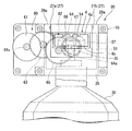
図4〜図6に示すように、ヘッド押下機構80は昇降ユニット50と、昇降ユニット50を上下動させる昇降用駆動機構60とによって構成されている。
昇降ユニット50は、筐体2の筐体本体11の内部に固定して設けられた昇降案内部材26によって上下方向の移動が案内されて昇降用駆動機構60の駆動によって昇降される昇降ベース51に、ポンプ付き容器30のポンプ32の押下ヘッド37が脱着可能に嵌め込まれるヘッド嵌合枠4を一体化したものである。
昇降ベース51、ヘッド嵌合枠4及び昇降案内部材26はプラスチック製であるが、これらの材質には特には限定はなく、金属製のものも採用可能である。
As shown in FIGS. 4 to 6, the head pressing mechanism 80 includes an elevating unit 50 and an elevating drive mechanism 60 that moves the elevating unit 50 up and down.
The elevating unit 50 is provided on an elevating base 51 that is guided by the elevating guide member 26 fixedly provided inside the housing main body 11 of the housing 2 and moved up and down by driving of the elevating drive mechanism 60. The head fitting frame 4 into which the pressing head 37 of the pump 32 of the container 30 with a pump is detachably fitted is integrated.
The elevating base 51, the head fitting frame 4 and the elevating guide member 26 are made of plastic. However, these materials are not particularly limited, and those made of metal can also be adopted.

図6に示すように、昇降ベース51は、平面視コ字形に形成され上下方向に延在する板状に形成され、昇降案内部材26によって装置前後方向(図6において上下方向)に垂直の向きに保持されたままその昇降が案内される。この昇降ベース51は、装置前後方向に垂直の主板部52と、この主板部52の装置左右方向(図6において左右方向)両端に突設されたリブ状の突壁部53とによって平面視コ字形に形成されている。前記突壁部53は、前記主板部52から、筐体本体11の背面側(背板部23b側。装置前後方向後側)に向かって突出されており、その突端が、昇降案内部材26の後述の板部26aに当接されている。   As shown in FIG. 6, the elevating base 51 is formed in a plate shape that is formed in a U shape in plan view and extends in the up-down direction, and is vertically oriented by the elevating guide member 26 in the longitudinal direction of the apparatus (up-down direction in FIG. 6). Ascending / descending is guided while being held in place. The elevating base 51 includes a main plate portion 52 that is perpendicular to the longitudinal direction of the apparatus and rib-shaped projecting wall portions 53 that protrude from both ends of the main plate portion 52 in the left-right direction (left-right direction in FIG. 6). It is formed in a letter shape. The protruding wall portion 53 protrudes from the main plate portion 52 toward the back side of the housing body 11 (the back plate portion 23b side, the rear side in the front-rear direction of the apparatus). It is in contact with a plate portion 26a described later.

図5、図6に示すように、図示例の昇降ベース51は、主板部52上端に筐体本体11の背面側(背板部23b側)に向かって突出された上端リブ52aを有している。この上端リブ52aは、装置左右方向両側の突壁部53を橋絡している。この上端リブ52aの主板部52から装置前後方向後側への突出寸法は、突壁部53の主板部52から装置前後方向後側への突出寸法と同じに揃えられている。
但し、昇降ベース51は、上端リブ52aの主板部52から装置前後方向後側への突出寸法は、突壁部53の主板部52からの突出寸法よりも小さくしても良く、また、上端リブ52aを省略しても良い。
As shown in FIGS. 5 and 6, the lifting base 51 of the illustrated example has an upper end rib 52 a that protrudes toward the back side (back plate portion 23 b side) of the housing body 11 at the upper end of the main plate portion 52. Yes. The upper end rib 52a bridges the protruding wall portions 53 on both sides in the left-right direction of the apparatus. The projecting dimension of the upper end rib 52a from the main plate part 52 to the rear side in the apparatus front-rear direction is aligned with the projecting dimension of the projecting wall part 53 from the main plate part 52 to the rear side in the apparatus front-rear direction.
However, in the elevating base 51, the protruding dimension of the upper end rib 52a from the main plate part 52 to the rear side in the front-rear direction of the apparatus may be smaller than the protruding dimension of the protruding wall part 53 from the main plate part 52. 52a may be omitted.

ヘッド嵌合枠4は昇降ベース51の前面側に装置前後方向前側へ向かって突出、延出されている。
ヘッド嵌合枠4は昇降ベース51に一体化されている。図示例の昇降ユニット50は、ヘッド嵌合枠4と昇降ベース51とを一体に樹脂成形したプラスチック製の一体成形品である。但し、昇降ユニット50としては、プラスチック製の一体成形品に限定されず、例えば昇降ベース51に該昇降ベース51とは別部材のヘッド嵌合枠4を固定して一体化した構成であっても良い。
The head fitting frame 4 protrudes and extends toward the front side of the apparatus front-rear direction on the front side of the lifting base 51.
The head fitting frame 4 is integrated with the lifting base 51. The lifting unit 50 in the illustrated example is an integrally molded product made of plastic in which the head fitting frame 4 and the lifting base 51 are integrally molded with resin. However, the lifting unit 50 is not limited to an integrally molded product made of plastic. For example, even if the head fitting frame 4, which is a separate member from the lifting base 51, is fixed to and integrated with the lifting base 51. good.

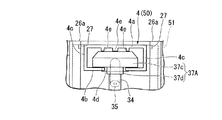
図4、図5に示すように、ヘッド嵌合枠4は、上下に離隔して互いに平行に設けられた平板状の上板部4a及び下板部4bが左右の側板部4cによって連結された四角枠状に形成されている。
図3〜図7に示すように、下板部4bの幅方向(左右方向)の中間部分には、該下板部4bの前端から昇降ベース51に向かって延びるスリット4dが形成されている。
As shown in FIGS. 4 and 5, the head fitting frame 4 has a flat plate-like upper plate portion 4 a and a lower plate portion 4 b that are spaced apart in the vertical direction and connected in parallel to each other by left and right side plate portions 4 c. It is formed in a square frame shape.
As shown in FIGS. 3-7, the slit 4d extended toward the raising / lowering base 51 from the front end of this lower board part 4b is formed in the intermediate part of the width direction (left-right direction) of the lower board part 4b.

ポンプ付き容器30の押下ヘッド37はステム34軸線に対して垂直の板状に形成された部分(ヘッド本体)を有する。自動吐出装置1の筐体2内に格納するポンプ付き容器30としては、押下ヘッド37のヘッド本体の高さ寸法(押下ヘッド37のステム34の軸線方向における寸法)が、ヘッド嵌合枠4の上板部4aと下板部4bとの間隔(離隔距離)と略同じものを用いる。
ヘッド嵌合枠4は、前記下板部4bのスリット4dにポンプ付き容器30のステム34を挿入することにより、押下ヘッド37のヘッド本体を上板部4aと下板部4bとの間に挿入して挟み込むことが可能となっている。
The pressing head 37 of the pump-equipped container 30 has a portion (head body) formed in a plate shape perpendicular to the axis of the stem 34. As the container 30 with a pump stored in the housing 2 of the automatic ejection device 1, the height of the head body of the pressing head 37 (the dimension of the pressing head 37 in the axial direction of the stem 34) is the same as that of the head fitting frame 4. The substantially same distance (separation distance) between the upper plate portion 4a and the lower plate portion 4b is used.
The head fitting frame 4 inserts the head body of the pressing head 37 between the upper plate portion 4a and the lower plate portion 4b by inserting the stem 34 of the pump-equipped container 30 into the slit 4d of the lower plate portion 4b. And can be inserted.

また、自動液吐出装置1の筐体2内に格納されているポンプ付き容器30は、筐体2の前カバー12を筐体本体11から取り外して筐体本体11前側を開放し、ヘッド嵌合枠4内側に嵌め込まれている押下ヘッド37、及び前記下板部4bのスリット4dに挿入されているステム34を、ヘッド嵌合枠4から装置前側へ抜き出すことで、筐体本体11から簡単に取り出すことができる。これにより、ポンプ付き容器30の交換を楽に行うことができる。   In addition, the pump-equipped container 30 stored in the housing 2 of the automatic liquid discharge apparatus 1 removes the front cover 12 of the housing 2 from the housing body 11 to open the front side of the housing body 11 and fit the head. The push-down head 37 fitted inside the frame 4 and the stem 34 inserted into the slit 4d of the lower plate portion 4b are pulled out from the head fitting frame 4 to the front side of the apparatus, so that it can be easily removed from the housing body 11. It can be taken out. Thereby, replacement | exchange of the container 30 with a pump can be performed easily.

図4、図6、図11等に示すように、ポンプ付き容器30の押下ヘッド37は、ステム34の軸線に対し垂直の平板状(図示例では円板状)に形成されており、ステム34の軸線に対して垂直の平面状の上面37a及び下面37bを有する。この押下ヘッド37は、その全体がヘッド本体として機能するものである。この押下ヘッド37において、高さ寸法は、前記下面37bから上面37aからの距離、すなわち、板状の押下ヘッド37の厚み寸法である。   As shown in FIGS. 4, 6, 11, etc., the pressing head 37 of the pump-equipped container 30 is formed in a flat plate shape (disc shape in the illustrated example) perpendicular to the axis of the stem 34. The upper surface 37a and the lower surface 37b are planar and perpendicular to the axis. The entire pressing head 37 functions as a head body. In the pressing head 37, the height dimension is the distance from the lower surface 37b to the upper surface 37a, that is, the thickness dimension of the plate-shaped pressing head 37.

但し、ポンプ付き容器30の押下ヘッド37としては、図12に示す押下ヘッド37Aのように、ステム34の軸線に対し垂直の板状のヘッド本体37cの下側に、ステム34上端部に外挿した筒状首部37dを突設したものも採用可能である。この押下ヘッド37Aは、ヘッド本体37cの厚み寸法が、ヘッド嵌合枠4の上板部4aと下板部4bとの間隔と略同じになっている。この押下ヘッド37Aは、筒状首部37dをヘッド嵌合枠4の前記下板部4bのスリット4dに挿入することで、ヘッド本体37cを、ヘッド嵌合枠4の上板部4aと下板部4bとの間に挿入して嵌め込むことができる。   However, the pressing head 37 of the container 30 with the pump is extrapolated to the upper end of the stem 34 below the plate-like head body 37c perpendicular to the axis of the stem 34, as in the pressing head 37A shown in FIG. It is also possible to employ a projecting cylindrical neck portion 37d. In the pressing head 37A, the thickness of the head main body 37c is substantially the same as the distance between the upper plate portion 4a and the lower plate portion 4b of the head fitting frame 4. The pressing head 37A inserts the cylindrical neck portion 37d into the slit 4d of the lower plate portion 4b of the head fitting frame 4 so that the head main body 37c is inserted into the upper plate portion 4a and the lower plate portion of the head fitting frame 4. 4b can be inserted and fitted.

また、ポンプ付き容器30の押下ヘッド37のヘッド本体としては、その高さ寸法が、ヘッド嵌合枠4の上板部4aと下板部4bとの間隔と略同じであり、ヘッド嵌合枠4の上板部4aと下板部4bとの間に嵌め込むことが可能なものであれば良く、ヘッド本体の形状には特に限定は無い。押下ヘッド37のヘッド本体としては、例えば図13(a)に示すように、上面が上に凸の外観ドーム形をなす板状のもの(ヘッド本体37e)、図13(b)に示すように、上面が凹曲面部をなす板状のもの(ヘッド本体37f)等も採用可能である。また、ヘッド本体としては、図13(c)に示すように、球状あるいは半球状(図示例は半球状)に形成されたもの(ヘッド本体37g)も採用可能である。
図13(a)〜(c)に例示したポンプ付き容器30の押下ヘッド37は、いずれも、ヘッド本体の下側に、ヘッド嵌合枠4の前記下板部4bのスリット4dに挿入可能な太さの筒状首部37dが突設された構成のものであるが、押下ヘッドとしては、筒状首部37dを有しておらず、ヘッド本体のみによって構成されているものも採用可能である。
Moreover, as a head main body of the pressing head 37 of the container 30 with a pump, the height dimension is substantially the same as the space | interval of the upper board part 4a and the lower board part 4b of the head fitting frame 4, and a head fitting frame There is no particular limitation on the shape of the head body as long as it can be fitted between the upper plate portion 4a and the lower plate portion 4b. As the head body of the pressing head 37, for example, as shown in FIG. 13 (a), a plate-like one (head body 37e) having an upwardly convex upper dome shape, as shown in FIG. 13 (b). Also, a plate-like one (head main body 37f) whose upper surface forms a concave curved surface portion can be employed. Further, as shown in FIG. 13C, a head body (head body 37g) formed in a spherical or hemispherical shape (in the illustrated example, a hemispherical shape) can also be used.
13A to 13C can be inserted into the slit 4d of the lower plate portion 4b of the head fitting frame 4 on the lower side of the head body. Although the cylindrical neck portion 37d having a thickness is projected, a pressing head that does not have the cylindrical neck portion 37d and is configured only by the head main body can be employed.

ヘッド嵌合枠4の上板部4aの下部には、装置前後方向に延在するリブ4eが複数突設されている。ヘッド嵌合枠4の上板部4aはこのリブ4eを含む。
複数のリブ4eは、装置左右方向に間隔を開けて複数箇所に突設されている。このリブ4eは、昇降ベース51から片持ち状に突出するヘッド嵌合枠4の昇降ベース51に対する曲げ強度を高める。その結果、ヘッド嵌合枠4は撓むことなく押下ヘッド37を押し下げることが可能となっている。
A plurality of ribs 4 e extending in the front-rear direction of the apparatus are provided on the lower portion of the upper plate portion 4 a of the head fitting frame 4. The upper plate portion 4a of the head fitting frame 4 includes the rib 4e.
The plurality of ribs 4e are provided to protrude at a plurality of locations at intervals in the left-right direction of the apparatus. The rib 4e increases the bending strength of the head fitting frame 4 protruding in a cantilever manner from the lifting base 51 with respect to the lifting base 51. As a result, the head fitting frame 4 can push down the pressing head 37 without bending.

図6に示すように、昇降案内部材26は筐体2の筐体本体11の内部に固定された支持板55に取り付けられている。支持板55は筐体本体11内面に突設された複数の支持突片11bにねじ56を用いてねじ止めして筐体本体11に、装置前後方向に直交する向きで固定されている。図示例の支持突片11bは、筐体本体11の背板部23bに突設されている。支持板55は、筐体本体11の背板部23bの支持突片11b以外の板状部分から前側に離隔した位置に設けられている。   As shown in FIG. 6, the elevating guide member 26 is attached to a support plate 55 fixed inside the housing body 11 of the housing 2. The support plate 55 is fixed to the housing main body 11 in a direction orthogonal to the front-rear direction of the apparatus by screwing a plurality of support protrusions 11b provided on the inner surface of the housing main body 11 with screws 56. The support protrusion 11 b in the illustrated example protrudes from the back plate portion 23 b of the housing body 11. The support plate 55 is provided at a position spaced forward from a plate-like portion other than the support protrusion 11 b of the back plate portion 23 b of the housing body 11.

昇降案内部材26は、支持板55の前面側(装置前後方向前側)に固定して上下方向に延在配置されている。昇降案内部材26は支持板55に当接した板部26bと、板部26bの左右方向両端部に装置前側に向かって突設された平面視L字形の鉤部26aとを有して構成されている。昇降案内部材26の左右両側の鉤部26aは、板部26bからの突出先端同士が、装置左右方向において互いに対向する平面視L字形に形成されている。   The elevating guide member 26 is fixed to the front surface side (front side in the apparatus front-rear direction) of the support plate 55 and is arranged to extend in the up-down direction. The elevating guide member 26 includes a plate portion 26b that is in contact with the support plate 55, and a flange portion 26a that is L-shaped in plan view and protrudes toward the front side of the apparatus at both left and right ends of the plate portion 26b. ing. The flange portions 26a on both the left and right sides of the elevating guide member 26 are formed in an L shape in a plan view in which protruding tips from the plate portion 26b face each other in the apparatus left-right direction.

昇降ユニット50のヘッド嵌合枠4は、昇降ベース51の装置左右方向中央部から前側(装置前後方向前側)へ突出されている。昇降ユニット50は、前記昇降ベース51の前記ヘッド嵌合枠4を介して左右両側に張り出す張出部を、それぞれ、昇降案内部材26の鉤部26aと板部26bとによって構成された平面視コ字状の案内部の内側に収納した状態で、昇降案内部材26に対して摺動しながら昇降する。また、昇降ユニット50は、前記昇降ベース51の左右両側の張出部が前記鉤部26aによって板部26bに押さえ込まれており、板部26bと鉤部26aとに摺動しながら、昇降案内部材26に対してがたつくことなく昇降する。
なお、昇降ユニット50のヘッド嵌合枠4は、昇降ユニット50の昇降に伴い、昇降案内部材26の左右両側の鉤部26aの間を昇降する。
The head fitting frame 4 of the elevating unit 50 protrudes from the central portion of the elevating base 51 in the left-right direction of the apparatus to the front side (front side in the apparatus front-rear direction). The elevation unit 50 is a plan view in which the overhanging portions projecting to the left and right sides via the head fitting frame 4 of the elevation base 51 are respectively constituted by the flange portions 26 a and the plate portions 26 b of the elevation guide member 26. In a state of being housed inside the U-shaped guide part, the elevator is moved up and down while sliding with respect to the lifting guide member 26. Further, the lifting unit 50 has the protruding portions on the left and right sides of the lifting base 51 pressed against the plate portion 26b by the flange portion 26a, and slides between the plate portion 26b and the flange portion 26a. Ascends and descends without shaking against 26.
The head fitting frame 4 of the elevating unit 50 moves up and down between the flange portions 26 a on the left and right sides of the elevating guide member 26 as the elevating unit 50 moves up and down.

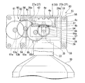
次に、この実施形態の自動吐出装置1のヘッド押下機構80の昇降用駆動機構60について説明する。
昇降用駆動機構60は筐体2の筐体本体11の内部に固定された支持板55に取り付けられている。図4、図5、図6に示すように、昇降用駆動機構60は支持板55の前面側に取り付けられたモータ61と、支持板55に軸支してその裏面(筐体本体11の背板部23aに臨む面)側に配置した複数のギア63、64、65によって減速機構を構成するギアユニット62とを有している。
Next, the elevating drive mechanism 60 of the head pressing mechanism 80 of the automatic ejection device 1 of this embodiment will be described.
The elevating drive mechanism 60 is attached to a support plate 55 fixed inside the housing body 11 of the housing 2. As shown in FIGS. 4, 5, and 6, the elevating drive mechanism 60 includes a motor 61 attached to the front side of the support plate 55 and a back surface (back of the housing body 11) that is pivotally supported by the support plate 55. A gear unit 62 that constitutes a speed reduction mechanism is provided by a plurality of gears 63, 64, 65 arranged on the side facing the plate portion 23 a.

図4、図5、図6に示すように、ギアユニット62は、モータ61の駆動ギア61aに噛合する入力ギア63と、一または複数の伝達ギア65(図示例ではひとつ)と、この伝達ギア65を介して伝達される前記入力ギア63からの回転駆動力によって回転駆動される出力ギア64とを有している。
また、出力ギア64のギア軸64aは、前記支持板55から、昇降案内部材26の板部26b中央部に開口された窓孔26c(図5参照)を貫通して前記板部26bの前側へ突出された部分(前側突出部)を有している。そして、昇降用駆動機構60は、前記ギア軸64aの前記前側突出部に固定して一体的に設けられたピン板67の前面側に突設した係合ピン66を、前記昇降ユニット50の昇降ベース51の主板部52に左右方向に延在形成された長孔状の係合スリット54に挿入している。
As shown in FIGS. 4, 5, and 6, the gear unit 62 includes an input gear 63 that meshes with the drive gear 61 a of the motor 61, one or a plurality of transmission gears 65 (one in the illustrated example), and the transmission gear. And an output gear 64 that is rotationally driven by the rotational driving force from the input gear 63 transmitted through 65.
Further, the gear shaft 64a of the output gear 64 passes from the support plate 55 through the window hole 26c (see FIG. 5) opened at the center of the plate portion 26b of the elevating guide member 26 to the front side of the plate portion 26b. It has a protruding portion (front protruding portion). The elevating drive mechanism 60 elevates and lowers the elevating unit 50 with an engaging pin 66 protruding from the front side of a pin plate 67 that is integrally fixed to the front protruding portion of the gear shaft 64a. The main plate portion 52 of the base 51 is inserted into a long hole-shaped engagement slit 54 that extends in the left-right direction.

入力ギア63は、モータ61の駆動ギア61aに噛合するメインギア63aに、該メインギア63aに比べて径小のサブギア63bを同軸に固定して一体化したものである。
前記伝達ギア65は、入力ギア63のサブギア63bに噛合するメインギア65aに、該メインギア65aに比べて径小のサブギア65bを同軸に固定して一体化したものであり、サブギア65bを出力ギア64に噛合させて、入力ギア63を介して伝達されるモータ61の回転駆動力を出力ギア64に伝達する。
なお、入力ギア63のメインギア63a、伝達ギア65のメインギア65a、出力ギア64は、入力ギア63のサブギア63b及び伝達ギア65のサブギア65bに比べて径大に形成されている。また、互いに噛み合わされたギア間では、駆動側ギアが従動側ギアに比べて径小で歯数が少なく、モータ61からの回転駆動力を減速して伝達する減速比が確保されている。
The input gear 63 is formed by integrating a sub-gear 63b having a smaller diameter than the main gear 63a coaxially with a main gear 63a that meshes with the drive gear 61a of the motor 61.
The transmission gear 65 is a main gear 65a meshing with the sub gear 63b of the input gear 63, and a sub gear 65b having a diameter smaller than that of the main gear 65a is coaxially fixed and integrated, and the sub gear 65b is integrated with the output gear. The rotational driving force of the motor 61 transmitted through the input gear 63 is transmitted to the output gear 64.
The main gear 63 a of the input gear 63, the main gear 65 a of the transmission gear 65, and the output gear 64 are formed larger in diameter than the sub gear 63 b of the input gear 63 and the sub gear 65 b of the transmission gear 65. Further, between the gears meshed with each other, the driving side gear has a smaller diameter and a smaller number of teeth than the driven side gear, and a reduction ratio for reducing and transmitting the rotational driving force from the motor 61 is ensured.

ギアユニット62は、モータ61の回転駆動力を減速して出力ギア64に伝達して出力ギア64及びピン板67を回転させる減速機構を構成するものであれば良く、図示例の構成に限定されない。
ギアユニット62としては、例えば、入力ギア63と出力ギア64との間に複数の伝達ギア65を設けた構成も採用可能である。この場合は、複数の伝達ギア65を、駆動側の伝達ギア65のサブギア65bに従動側の伝達ギア65のメインギア65aを噛み合わせ、回転駆動力伝達方向において最も駆動側に位置する伝達ギア65のメインギア65aを入力ギア63のサブギア63bに噛み合わせ、最も従動側に位置する伝達ギア65のサブギア65bを出力ギア64に噛み合わせる。
また、ギアユニット62としては、伝達ギア65を省略して、入力ギア63のサブギア63bに出力ギア64を直接噛み合わせた構成も採用可能である。
The gear unit 62 only needs to constitute a reduction mechanism that decelerates the rotational driving force of the motor 61 and transmits it to the output gear 64 to rotate the output gear 64 and the pin plate 67, and is not limited to the configuration of the illustrated example. .
As the gear unit 62, for example, a configuration in which a plurality of transmission gears 65 are provided between the input gear 63 and the output gear 64 can be employed. In this case, the plurality of transmission gears 65 mesh with the main gear 65a of the driven-side transmission gear 65 of the driving-side transmission gear 65, and the transmission gear 65 located closest to the driving side in the rotational driving force transmission direction. The main gear 65 a is meshed with the sub gear 63 b of the input gear 63, and the sub gear 65 b of the transmission gear 65 located closest to the driven side is meshed with the output gear 64.
As the gear unit 62, a configuration in which the transmission gear 65 is omitted and the output gear 64 is directly meshed with the sub gear 63b of the input gear 63 can be employed.

前記昇降用駆動機構60は、モータ61の回転駆動によって出力ギア64が回転すると、ピン板67が出力ギア64のギア軸64aと一体に回転する。ピン板67における係合ピン66の突設位置は、出力ギア64のギア軸64aに対し偏心されている。このため、モータ61の駆動によってピン板67が回転すると、この回転によって係合ピン66はギア軸64aを中心とした円周上を移動(回動)する円運動を行う。既述のように、係合ピン66は昇降ベース51の主板部52に形成されている係合スリット54に挿入されているため、係合ピン66が円運動を行うと、昇降ベース51に上下方向の移動力が作用して、係合ピン66の回動に伴い昇降ユニット50が昇降案内部材26に案内されながら上下方向に移動する。これによりヘッド嵌合枠4による押下ヘッド37の押し下げ及び引き上げを行うことができる。   In the elevating drive mechanism 60, when the output gear 64 is rotated by the rotation drive of the motor 61, the pin plate 67 rotates integrally with the gear shaft 64 a of the output gear 64. The protruding position of the engagement pin 66 on the pin plate 67 is eccentric with respect to the gear shaft 64 a of the output gear 64. Therefore, when the pin plate 67 is rotated by driving the motor 61, the engagement pin 66 performs a circular motion that moves (rotates) on the circumference around the gear shaft 64a. As described above, since the engaging pin 66 is inserted into the engaging slit 54 formed in the main plate portion 52 of the elevating base 51, when the engaging pin 66 performs a circular motion, the elevating base 51 is moved up and down. The moving force in the direction acts, and the lifting unit 50 moves in the vertical direction while being guided by the lifting guide member 26 as the engaging pin 66 rotates. Thereby, the pressing head 37 can be pushed down and pulled up by the head fitting frame 4.

ピン板67の回転に伴う係合ピン66の回動は、係合スリット54長手方向における挿入位置の移動を伴って進行する。係合スリット54の長手方向寸法は、ピン板67の回転によって回動する係合ピン66の装置左右方向の変位量(移動量)よりも長い。装置左右方向における係合スリット54の形成範囲は、ピン板67が1回転したときの係合ピン66の装置左右方向における可動範囲よりも広く、係合ピン66はピン板67の回転によって係合スリット54に挿入された状態を維持したまま出力ギア64のギア軸64aの軸線を中心に回動する。
また、係合スリット66の長手方向に直交する幅方向(上下方向)の寸法は、係合ピン66外径と略同等(同等又は僅かに大きい)に揃えられている。
The rotation of the engagement pin 66 accompanying the rotation of the pin plate 67 proceeds with the movement of the insertion position in the longitudinal direction of the engagement slit 54. The longitudinal dimension of the engagement slit 54 is longer than the displacement amount (movement amount) of the engagement pin 66 rotated by the rotation of the pin plate 67 in the lateral direction of the apparatus. The formation range of the engagement slit 54 in the left-right direction of the device is wider than the movable range of the engagement pin 66 in the left-right direction of the device when the pin plate 67 rotates once, and the engagement pin 66 is engaged by the rotation of the pin plate 67. While maintaining the state of being inserted into the slit 54, the output gear 64 rotates around the axis of the gear shaft 64a.
In addition, the dimension in the width direction (vertical direction) orthogonal to the longitudinal direction of the engagement slit 66 is substantially the same (equal or slightly larger) than the outer diameter of the engagement pin 66.

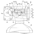
図4、図7に示すように、この自動液吐出装置1は、液吐出動作を行っていないとき、すなわちヘッド押下機構80の昇降用駆動機構60のモータ61が駆動されていないときには、係合ピン66が、ピン板67の回転による移動ルートにおける最上部である待機位置に配置される。
昇降ベース51及びポンプ付き容器30の押下ヘッド37の昇降ストロークは、ピン板67の回転による係合ピン66の回動半径によって決まる。昇降ベース51及びポンプ付き容器30の押下ヘッド37の昇降ストロークは、係合ピン66が待機位置にあるときが上限位置(昇降上限位置)であり、係合ピン66がその回動の中心を介して前記待機位置とは反対側に位置するとき、すなわち係合ピン66がその回動による移動ルートにおける最下部(図9に示す位置。以下、回動下端位置とも言う)に位置するときが下限位置(昇降下限位置)である。
As shown in FIGS. 4 and 7, the automatic liquid ejection device 1 is engaged when the liquid ejection operation is not performed, that is, when the motor 61 of the elevating drive mechanism 60 of the head pressing mechanism 80 is not driven. The pin 66 is disposed at a standby position that is the uppermost part in the movement route by the rotation of the pin plate 67.
The raising / lowering strokes of the raising / lowering base 51 and the press-down head 37 of the pump-equipped container 30 are determined by the turning radius of the engaging pin 66 by the rotation of the pin plate 67. The raising / lowering stroke of the raising / lowering base 51 and the pressing head 37 of the pump-equipped container 30 is an upper limit position (elevation upper / lower position) when the engagement pin 66 is in the standby position, and the engagement pin 66 passes through the center of rotation. When the position is opposite to the standby position, that is, when the engaging pin 66 is located at the lowest position (position shown in FIG. It is the position (lowering lower limit position).

昇降用駆動機構60の駆動による押下ヘッド37の押し下げは、図7〜図9に示すように係合ピン66がピン板67の回転によって待機位置から半円を描いて回動下端位置に到達する間に行われる。押下ヘッド37の押し下げにより、ポンプ付き容器30の吐出ノズル35から液体の吐出が行われる。図9〜図10に示すように、押下ヘッド37は、押し下げ完了後、係合ピン66がピン板67の回転によって回動下端位置から半円を描いて待機位置に到達することで、昇降上限位置に復帰する。   As shown in FIGS. 7 to 9, when the push-down head 37 is pushed down by the drive of the elevating drive mechanism 60, the engaging pin 66 draws a semicircle from the standby position by the rotation of the pin plate 67 and reaches the rotation lower end position. Between. By depressing the pressing head 37, the liquid is discharged from the discharge nozzle 35 of the pump-equipped container 30. As shown in FIGS. 9 to 10, the pressing head 37 is configured so that after the pressing is completed, the engaging pin 66 draws a semicircle from the rotating lower end position by the rotation of the pin plate 67 and reaches the standby position, thereby raising and lowering the upper limit. Return to position.

ポンプ付き容器30は、押下ヘッド37が容器31に対して昇降することで、ノズル付き押下レバー32A全体が容器31に対して昇降する。したがって、ポンプ付き容器30は、昇降用駆動機構60の駆動によって押下ヘッド37が昇降上限位置から押し下げられることで、吐出ノズル35から液体を吐出できる。また、ポンプ付き容器30は、押し下げの完了した押下ヘッド37が昇降下限位置から昇降上限位置に復帰することで、吸い上げ管40(図11参照)内の液体をシリンダ部32Bの液充填室36a内に吸い上げる。   In the pump-equipped container 30, the entire push-down lever 32 </ b> A with a nozzle moves up and down with respect to the container 31 as the pressing head 37 moves up and down relative to the container 31. Therefore, the pump-equipped container 30 can discharge the liquid from the discharge nozzle 35 by the pressing head 37 being pushed down from the up / down upper limit position by driving of the up / down drive mechanism 60. Moreover, the container 30 with a pump returns the liquid in the suction pipe 40 (refer FIG. 11) to the liquid filling chamber 36a of the cylinder part 32B, when the pressing head 37 which has been pushed down returns from the lower limit position to the upper limit position. Suck it up.

モータ61の駆動は、制御部21によって制御されている。制御部21はセンサ7がユーザーの手指を検出したときに出力する検出信号が入力されると、モータ61を駆動する。モータ61が駆動することにより係合ピン66が待機位置から円運動を開始し、回動下端位置を経由して待機位置に復帰する。昇降用駆動機構60の駆動によるピン板67の回転方向、係合ピン66の回動方向は一定であり、図示例では右回り方向になっている。   The driving of the motor 61 is controlled by the control unit 21. The control unit 21 drives the motor 61 when a detection signal output when the sensor 7 detects the user's finger is input. When the motor 61 is driven, the engagement pin 66 starts circular movement from the standby position, and returns to the standby position via the rotation lower end position. The rotation direction of the pin plate 67 and the rotation direction of the engagement pin 66 by the drive of the elevating drive mechanism 60 are constant, and are clockwise in the illustrated example.

昇降用駆動機構60は、係合ピン66が待機位置にある状態で、センサ7がユーザーの手指を検出したときに、制御部21の制御によって、係合ピン66を待機位置から回動下端位置を経由して待機位置に復帰させるピン回動動作を予め設定した回数(1回又は複数回)だけ実行する。1回のピン回動動作によって、ポンプ付き容器30のノズル付き押下レバー32Aを昇降上限位置から昇降下限位置まで押し下げてから昇降上限位置に復帰させるまでの1サイクルの吐出動作(昇降動作)が行われる。
また、昇降用駆動機構60は、係合ピン66の回動動作(ピン回動動作)を開始してから設定回数のピン回動動作が完了するまで、係合ピン66の回動を停止することなく、一定速度で係合ピン66を回動させる。
When the sensor 7 detects the user's finger while the engagement pin 66 is in the standby position, the elevating drive mechanism 60 rotates the engagement pin 66 from the standby position to the lower end position under the control of the control unit 21. The pin rotation operation for returning to the standby position via is performed a predetermined number of times (one or more times). With one pin rotation operation, a one-cycle discharge operation (elevating operation) is performed from when the push-down lever 32A with the nozzle of the pump-equipped container 30 is pushed down from the elevating upper limit position to the elevating lower limit position and returning to the elevating upper limit position. Is called.
Further, the elevating drive mechanism 60 stops the rotation of the engagement pin 66 from the start of the rotation operation (pin rotation operation) of the engagement pin 66 until the set number of pin rotation operations is completed. Without engaging, the engaging pin 66 is rotated at a constant speed.

昇降用駆動機構60は、ピン回動動作を行っていない状態において、ユーザーの手指を検出していないセンサ7が前記手指を検出したときに、ピン回動動作を実行する。ピン回動動作中から動作完了後までセンサ7が前記手指の検出を継続しているときは、設定回数のピン回動動作の完了後に、センサ7が手指を検出していない状態にしてからセンサ7が手指を検出することで、次回のピン回動動作が実行される。   The lift drive mechanism 60 performs the pin rotation operation when the sensor 7 not detecting the user's finger detects the finger in a state where the pin rotation operation is not performed. When the sensor 7 continues to detect the finger from during the pin rotation operation to after the operation is completed, after the set number of times of the pin rotation operation is completed, the sensor 7 does not detect the finger and then the sensor 7 When 7 detects a finger, the next pin rotation operation is executed.

図4、図7に示すように、この自動液吐出装置1は、筐体本体11内に、昇降上限位置に存在する昇降ユニット50を検出するリミットセンサ27を有する。リミットセンサ27が昇降ユニット50を検出しているとき、リミットセンサ27から出力される検出信号が制御部21に入力される。制御部21は、昇降用駆動機構60のモータ61が停止しており、かつリミットセンサ27が昇降ユニット50を検出している状態で、ユーザーの手指を検出したセンサ7から検出信号が入力されたときのみ、前記モータ61を駆動させて昇降用駆動機構60によるピン回動動作が開始させる。リミットセンサ27が昇降ユニット50を検出していない状態では、制御部21にユーザーの手指を検出したセンサ7から検出信号が入力されても、制御部21におけるセンサ7からの検出信号に基づくモータ61の制御はキャンセルされ、昇降用駆動機構60のピン回動動作は開始されない。   As shown in FIGS. 4 and 7, the automatic liquid ejecting apparatus 1 has a limit sensor 27 that detects an elevating unit 50 present at an elevating upper limit position in the housing body 11. When the limit sensor 27 detects the lifting unit 50, a detection signal output from the limit sensor 27 is input to the control unit 21. The control unit 21 receives a detection signal from the sensor 7 that detects the user's finger while the motor 61 of the lifting drive mechanism 60 is stopped and the limit sensor 27 detects the lifting unit 50. Only when the motor 61 is driven, the pin rotating operation by the elevating drive mechanism 60 is started. In a state where the limit sensor 27 does not detect the lifting unit 50, even if a detection signal is input from the sensor 7 that detects the user's finger to the control unit 21, the motor 61 based on the detection signal from the sensor 7 in the control unit 21. This control is canceled, and the pin rotation operation of the elevating drive mechanism 60 is not started.

センサ7がユーザーの手指を検出したときの昇降用駆動機構60のピン回動動作の設定回数が1回であるとき、ユーザーの手指を検出したセンサ7からの検出信号に基づいて制御部21の制御によって開始されたモータ61の駆動は、昇降ユニット50を検出したリミットセンサ27からの検出信号が制御部21に入力されることにより停止する。
センサ7がユーザーの手指を検出したときの昇降用駆動機構60のピン回動動作の設定回数が複数回であるとき、制御部21は、昇降ユニット50を検出したリミットセンサ27からの検出信号の入力によってピン回動動作の完了回数をカウントする。そして、制御部21は、最終回のピン回動動作によって下降され昇降上限位置に復帰した昇降ユニット50をリミットセンサ27が検出し、該リミットセンサ27からの検出信号が入力されることで、モータ61の駆動を停止させる。
When the set number of times of the pin rotation operation of the ascending / descending drive mechanism 60 when the sensor 7 detects the user's finger is one, based on the detection signal from the sensor 7 that has detected the user's finger, the controller 21 The driving of the motor 61 started by the control is stopped when a detection signal from the limit sensor 27 that detects the elevating unit 50 is input to the control unit 21.
When the number of times of setting the pin rotation operation of the lifting drive mechanism 60 when the sensor 7 detects the user's finger is a plurality of times, the control unit 21 detects the detection signal from the limit sensor 27 that has detected the lifting unit 50. The number of pin rotation operations completed is counted by input. Then, the control unit 21 detects the lifting unit 50 that has been lowered by the final pin rotation operation and returned to the lifting upper limit position, and the limit sensor 27 detects the lift unit 50, and the detection signal from the limit sensor 27 is input, so that the motor The drive of 61 is stopped.

図7〜図10に例示するリミットセンサ27は、昇降案内部材26にその左右方向に互いに離隔させて取り付け対向配置した発光部27aと受光部27bとからなる光センサである。このリミットセンサ27の発光部27a及び受光部27bは、昇降ユニット50が昇降上限位置にあるときのヘッド嵌合枠4の上板部4aの配置位置を介してその両側位置に互いに対向させて設けられ、上板部4aの検出によって昇降上限位置の昇降ユニット50を検出する。
なお、リミットセンサ27としては、昇降上限位置にある昇降ユニット50を検出するものであれば良く、上述の光センサ等に限定されない。このリミットセンサ27としては、上述の光センサ等の非接触形センサの他、昇降ユニット50との接触によって昇降上限位置にある昇降ユニット50を検出を行う接触形センサであっても良い。
The limit sensor 27 illustrated in FIGS. 7 to 10 is an optical sensor that includes a light emitting portion 27a and a light receiving portion 27b that are attached to the lifting guide member 26 so as to be spaced apart from each other in the left-right direction. The light emitting part 27a and the light receiving part 27b of the limit sensor 27 are provided opposite to each other at both side positions via the arrangement position of the upper plate part 4a of the head fitting frame 4 when the elevating unit 50 is at the elevating upper limit position. The upper / lower unit 50 at the upper / lower position is detected by detecting the upper plate portion 4a.
The limit sensor 27 is not limited to the above-described optical sensor and the like as long as it detects the lifting unit 50 at the lifting upper limit position. The limit sensor 27 may be a contact sensor that detects the lifting unit 50 at the lifting upper limit position by contact with the lifting unit 50 in addition to the above-described non-contact type sensor such as an optical sensor.

この自動液吐出装置1は、四角枠状のヘッド嵌合枠4によってポンプ付き容器30の押下ヘッド37を上下から挟持するため、押下ヘッド37がヘッド嵌合枠4に対して位置ずれを生じることがない。このため、押下ヘッド37の位置ずれに起因したステム34の斜め押しがなくなり、ヘッド押下機構80の押下ヘッド37の押し下げ動作(この実施形態の自動液吐出装置1にあってはピン回動動作)の開始から吐出ノズル35からの液体吐出開始までの時間を安定化することができる。   Since the automatic liquid discharge device 1 holds the pressing head 37 of the container 30 with a pump from above and below by the square frame-shaped head fitting frame 4, the pressing head 37 is displaced from the head fitting frame 4. There is no. Therefore, the stem 34 is not pushed obliquely due to the displacement of the pressing head 37, and the pressing operation of the pressing head 37 of the head pressing mechanism 80 is performed (in the automatic liquid ejecting apparatus 1 of this embodiment, a pin rotating operation). The time from the start to the start of liquid discharge from the discharge nozzle 35 can be stabilized.

また、この自動液吐出装置1は、図14に例示した従来技術で生じていた、板状の押下部材120に対する押下ヘッド114の滑りに起因するステムの撓み変形を防ぐことができる。このため、この自動液吐出装置1は、板状の押下部材120に対する押下ヘッド114の滑りに起因する撓み変形によってステムを傷める心配が無く、その結果、ポンプ付き容器の寿命を延長できるといった利点もある。   Further, the automatic liquid ejection device 1 can prevent the bending deformation of the stem caused by the sliding of the pressing head 114 with respect to the plate-shaped pressing member 120, which has occurred in the prior art illustrated in FIG. 14. For this reason, this automatic liquid discharge apparatus 1 has the advantage that there is no fear of damaging the stem due to bending deformation caused by the sliding of the pressing head 114 with respect to the plate-shaped pressing member 120, and as a result, the life of the container with the pump can be extended. is there.

また、この自動液吐出装置1のヘッド押下機構80は、昇降ユニット50の押し下げのみならず、押し下げの完了した昇降ユニット50の昇降上限位置への復帰をも行う。このため、この自動液吐出装置1は、ヘッド押下機構80の駆動によって、押し下げ完了後の昇降ユニット50を上昇させることで、昇降ユニット50のヘッド嵌合枠4に嵌合状態の押下ヘッド37も昇降ユニット50とともに上昇させ、押し下げ前の位置、すなわち昇降上限位置に確実に復帰させることができる。
このため、この自動液吐出装置1は、何らかの原因で、容器31に対するステム34の移動抵抗が若干増大した場合であっても、押し下げ完了後のノズル付き押下レバー32Aの昇降下限位置から昇降上限位置への復帰に要する時間が長くなることを防ぐことができ、該時間を安定化することができる。
Further, the head pressing mechanism 80 of the automatic liquid ejection apparatus 1 not only depresses the lifting unit 50 but also returns the lifting unit 50 that has been pressed down to the upper limit position. For this reason, the automatic liquid discharge apparatus 1 raises the lifting unit 50 after the completion of the pressing operation by driving the head pressing mechanism 80, so that the pressing head 37 fitted to the head fitting frame 4 of the lifting unit 50 is also connected. It can be lifted together with the lift unit 50 and reliably returned to the position before the push-down, that is, the lift upper limit position.
For this reason, even if the movement resistance of the stem 34 with respect to the container 31 is slightly increased for some reason, the automatic liquid ejection device 1 moves from the lower limit position of the push-down lever 32A with the nozzle after the completion of pressing down to the upper limit position. It is possible to prevent the time required for returning to the time from becoming long and to stabilize the time.

なお、この自動液吐出装置1にあっては、上述のように、従来技術における板状の押下部材120に対する押下ヘッド114の滑りに起因するステムの撓み変形を防止できるため、該滑りに起因する撓み変形によるステムのキャップに対する摺動抵抗の増大、それによる押し下げ完了後のステム及び押下ヘッドの上昇の遅れを生じる心配は無い。   In the automatic liquid ejecting apparatus 1, as described above, the stem can be prevented from being bent and deformed due to the sliding of the pressing head 114 with respect to the plate-shaped pressing member 120 in the prior art. There is no fear of causing an increase in sliding resistance against the cap of the stem due to bending deformation, thereby causing a delay in raising of the stem and the pressing head after completion of the pressing down.

さらに、この自動液吐出装置1は、例えば比較的粘度が高い液体をポンプ付き容器30から吐出した場合でも、ヘッド押下機構80の駆動によって、押し下げ完了後の昇降ユニット50を上昇させることで、昇降ユニット50のヘッド嵌合枠4に嵌合状態の押下ヘッド37も昇降ユニット50とともに上昇させ昇降上限位置に確実に復帰させることができる。したがって、押下ヘッドの上昇の遅れによって次回吐出動作までの待機時間が長くなるといった不都合の発生を防ぐことができる。   Further, the automatic liquid ejecting apparatus 1 elevates the elevating unit 50 after the depressing is completed by driving the head depressing mechanism 80 even when, for example, a liquid having a relatively high viscosity is ejected from the container 30 with the pump. The pressing head 37 fitted to the head fitting frame 4 of the unit 50 can also be raised together with the lifting unit 50 and reliably returned to the lifting upper limit position. Therefore, it is possible to prevent the occurrence of inconvenience that the waiting time until the next discharge operation becomes longer due to the delay of the raising of the pressing head.

上述の実施形態のヘッド押下機構80の昇降用駆動機構60は、減速機構を構成するギアユニット62の減速比によって、ポンプ付き容器30のシリンダ部32B内のリターンスプリング39の弾性付勢力の作用や、ポンプ付き容器30から吐出する液体の粘度に影響を受けることなく、ポンプ付き容器30のノズル付き押下レバー32Aの押下ヘッド37の押し下げと、押し下げ後の昇降上限位置への上昇、復帰とを同じ速度で円滑に行うことが可能である。
つまり、昇降用駆動機構60は、ポンプ付き容器30のノズル付き押下レバー32Aの昇降抵抗が多少大きくなっても、減速機構を構成するギアユニット62の減速比によって昇降ユニット50の昇降速度が全くあるいは殆ど影響を受けることなく、昇降ユニット50の昇降に押下ヘッド37を追従させて押下ヘッド37を円滑に昇降させることができる。
The raising / lowering drive mechanism 60 of the head pressing mechanism 80 of the above-described embodiment is based on the action of the elastic biasing force of the return spring 39 in the cylinder portion 32B of the pump-equipped container 30 according to the reduction ratio of the gear unit 62 constituting the reduction mechanism. The depression of the push-down head 37 of the push-down lever 32A with the nozzle of the pump-equipped container 30 is the same as the rise and return to the upper and lower lift upper limit position without being affected by the viscosity of the liquid discharged from the pump-equipped container 30. It can be done smoothly at speed.
That is, in the lifting drive mechanism 60, even if the lifting resistance of the push-down lever 32A with the nozzle of the pump-equipped container 30 is somewhat increased, the lifting speed of the lifting unit 50 may be completely or depending on the reduction ratio of the gear unit 62 that constitutes the speed reduction mechanism. The pressing head 37 can be raised and lowered smoothly by following the raising and lowering of the lifting unit 50 with almost no influence.

また、ヘッド押下機構80が、昇降ユニット50の押し下げのみならず、押し下げの完了した昇降ユニット50の昇降上限位置への復帰をも行う構成は、例えばキャップ33に対するステム34の摺動抵抗の増大や、ポンプ付き容器30の容器31内の液体の粘度等によって、押し下げ後のノズル付き押下レバー32Aの上昇抵抗が増大したときに、昇降ユニット50の上昇によってノズル付き押下レバー32Aの押下レバー37を引き上げることでステム34に引っ張り力を作用させることができる。その結果、ステム34の撓み変形を解消あるいは小さくすることができる。   The configuration in which the head pressing mechanism 80 not only depresses the elevating unit 50 but also returns the elevating unit 50 that has been depressed to the elevating upper limit position, for example, increases the sliding resistance of the stem 34 relative to the cap 33. When the ascending resistance of the push-down lever 32A with the nozzle after being pushed down increases due to the viscosity of the liquid in the container 31 of the pump-equipped vessel 30, the push-down lever 37 of the push-down lever 32A with the nozzle is pulled up by the raising / lowering unit 50. Thus, a pulling force can be applied to the stem 34. As a result, the bending deformation of the stem 34 can be eliminated or reduced.

図11に示すように、昇降用駆動機構60の駆動によるポンプ付き容器30の押下ヘッド37の昇降上限位置が、ポンプ付き容器30における構造上の押下ヘッド37の上昇限界位置よりも下方に位置する構成は、ポンプ付き容器30におけるシリンダ部32Bの液充填室36a内へのエアの侵入に起因するポンプミスの防止に有効に寄与する。   As shown in FIG. 11, the upper and lower upper limit position of the press-down head 37 of the pump-equipped container 30 driven by the elevating drive mechanism 60 is positioned below the upper limit position of the push-down head 37 in the structure of the pump-equipped container 30. The configuration effectively contributes to prevention of pump mistakes due to the intrusion of air into the liquid filling chamber 36a of the cylinder portion 32B in the pump-equipped container 30.

本発明者は、仮に、図11に示すポンプ付き容器30を、図14に例示した従来の自動液吐出装置に適用し、ポンプ付き容器30のノズル付き押下レバー32Aを板状の押下部材120によって上昇限界位置から押し下げ、液吐出後にリターンスプリング39の弾性付勢力のみによって上昇限界位置に復帰させる構成とした場合について検証した。この場合、押下ヘッド37を押し下げて液体を吐出ノズル35から吐出する際に液体の円滑な吐出ができないポンプミスを生じることがあることを把握した。このポンプミスは、ポンプケース36内の液充填室36aへのエア侵入によって生じている。液充填室36aへのエアの侵入は、押下部材120が押下ヘッド37を上昇限界位置から押し下げる際に、ステム34が斜め押しの状態となることに起因する。   The inventor temporarily applies the pump-equipped container 30 shown in FIG. 11 to the conventional automatic liquid discharge apparatus illustrated in FIG. 14, and the push-down lever 32 </ b> A of the pump-equipped container 30 is moved by the plate-shaped pressing member 120. The case where the structure is configured such that it is pushed down from the ascending limit position and returned to the ascending limit position only by the elastic biasing force of the return spring 39 after discharging the liquid was verified. In this case, it has been found that when the liquid is discharged from the discharge nozzle 35 by depressing the pressing head 37, a pump error may occur in which the liquid cannot be discharged smoothly. This pump error is caused by air intrusion into the liquid filling chamber 36 a in the pump case 36. The intrusion of air into the liquid filling chamber 36a is caused by the stem 34 being in an obliquely pushed state when the pressing member 120 pushes down the pressing head 37 from the rising limit position.

ポンプ付き容器30の構成部材はプラスチック製であることが一般的であり、図11に例示したポンプ付き容器30は、ボール式逆止弁41、42cのボール及びリターンスプリング39を除く全ての部材がプラスチック製である。ステム34が斜め押しの状態になると、シリンダ部32B内のピストン38がポンプケース36内周面を押圧することによって、ポンプケース36がステム収納筒部33bの軸線に対して僅かに傾くことがある。このとき、ポンプケース36は、キャップ33に固定されている部分から下方に延出する部分(以下、下側延出部)の上端の変形によってステム収納筒部33bに対して傾いている。このため、ノズル付き押下レバー32Aが上昇限界位置にあるとき、ポンプケース36の下側延出部上端の変形が、ピストン38とポンプケース36内周面との間のシール性に影響を与え、液充填室36a内へのエア侵入の原因となる。   The components of the pump-equipped container 30 are generally made of plastic. The pump-equipped container 30 illustrated in FIG. 11 has all members except the balls of the ball check valves 41 and 42c and the return spring 39. Made of plastic. When the stem 34 is in an obliquely pressed state, the piston 38 in the cylinder portion 32B presses the inner peripheral surface of the pump case 36, so that the pump case 36 may be slightly inclined with respect to the axis of the stem housing cylinder portion 33b. . At this time, the pump case 36 is inclined with respect to the stem storage cylinder portion 33b due to deformation of the upper end of a portion (hereinafter referred to as a lower extension portion) extending downward from a portion fixed to the cap 33. For this reason, when the pressing lever 32A with the nozzle is at the ascent limit position, the deformation of the upper end of the lower extension of the pump case 36 affects the sealing performance between the piston 38 and the inner peripheral surface of the pump case 36, This causes air intrusion into the liquid filling chamber 36a.

ステム34とステム収納筒部33bとの間には、ノズル付き押下レバー32Aが上昇限界位置よりも下方に位置するときにピストン38と天井壁33bとの間に形成される空間に連通するエア通路が、例えばステム収納筒部33b内周面に形成した溝によって確保されている。ポンプケース36の下側延出部上端に変形が生じていると、ノズル付き押下レバー32Aが上昇限界位置にあるときに、液充填室36a内へのエア侵入と、逆止弁41から吸い上げ管40への液漏出とによって液充填室36a内の液量が減少することがあり、この液量減少によってポンプミスが発生する。
なお、液吐出後のポンプ付き容器30のノズル付き押下レバー32Aの吐出用流路42は、レバー下端逆止弁42cから液出口42b側に充填された液体によって塞がれた状態になっているため、この吐出用流路42から液充填室36aへのエア侵入は生じにくい。
An air passage between the stem 34 and the stem storage cylinder portion 33b communicates with a space formed between the piston 38 and the ceiling wall 33b when the push-down lever 32A with a nozzle is positioned below the rising limit position. However, it is ensured by a groove formed on the inner peripheral surface of the stem storage cylinder portion 33b, for example. When the upper end of the lower extension of the pump case 36 is deformed, the air intrusion into the liquid filling chamber 36a and the suction pipe from the check valve 41 when the push-down lever 32A with the nozzle is at the upper limit position. The amount of liquid in the liquid filling chamber 36a may decrease due to the liquid leakage to 40, and a pump error occurs due to the decrease in the liquid amount.
The discharge flow path 42 of the push-down lever 32A with the nozzle of the pump-equipped container 30 after the liquid discharge is in a state of being blocked by the liquid filled from the lever lower end check valve 42c to the liquid outlet 42b side. Therefore, it is difficult for air to enter the liquid filling chamber 36a from the discharge flow path 42.

本実施形態の自動液吐出装置1は、筐体2内に格納したポンプ付き容器30の押下ヘッド37の押し下げ時にステム34の斜め押しを生じない。しかしながら、ポンプ付き容器30の押下ヘッド37の押し下げ時のステム34の若干の撓み変形によって、プラスチック製のポンプケース36の下側延出部のキャップ33に対する微小な傾動が繰り返し作用し、ポンプケース36の下側延出部の上端に微小な変形を生じる可能性はある。
図11に示すように、昇降用駆動機構60の駆動によるポンプ付き容器30の押下ヘッド37の昇降上限位置が、ポンプ付き容器30における構造上の押下ヘッド37の上昇限界位置よりも下方に位置する構成であれば、昇降用駆動機構60が駆動していない待機状態時に昇降上限位置に静止するノズル付き押下レバー32Aのピストン38が、シリンダ部32Bの天井壁33bから若干下方に配置される。すなわち、昇降上限位置のノズル付き押下レバー32Aのピストン38を、ポンプケース36の下側延出部の上端を避けて、その下方にずれた位置に配置できる。これにより、ポンプケース36の下側延出部上端の微小な変形が、ピストン38とポンプケース36内周面との間のシール性に影響を与えることによる液充填室36a内へのエア侵入を防ぐことができる。
The automatic liquid ejection device 1 of the present embodiment does not cause the stem 34 to be obliquely pushed when the push-down head 37 of the container 30 with a pump stored in the housing 2 is pushed down. However, a slight tilting of the lower extension portion of the plastic pump case 36 with respect to the cap 33 repeatedly acts due to slight deformation of the stem 34 when the pressing head 37 of the pump-equipped container 30 is pushed down. There is a possibility that a minute deformation may occur at the upper end of the lower extension portion of the.
As shown in FIG. 11, the upper and lower upper limit position of the press-down head 37 of the pump-equipped container 30 driven by the elevating drive mechanism 60 is positioned below the upper limit position of the push-down head 37 in the structure of the pump-equipped container 30. If it is a structure, the piston 38 of the pressing lever 32A with a nozzle which stops at the raising / lowering upper limit position at the time of the standby state which the raising / lowering drive mechanism 60 is not driving is arrange | positioned slightly downward from the ceiling wall 33b of the cylinder part 32B. That is, the piston 38 of the push-down lever 32A with the nozzle at the upper and lower limit position can be disposed at a position shifted downward below the upper end of the lower extension portion of the pump case 36. As a result, the minute deformation at the upper end of the lower extension of the pump case 36 affects the sealing performance between the piston 38 and the inner peripheral surface of the pump case 36, thereby preventing air from entering the liquid filling chamber 36a. Can be prevented.

また、昇降用駆動機構60の駆動によるポンプ付き容器30の押下ヘッド37の昇降上限位置が、ポンプ付き容器30における構造上の押下ヘッド37の上昇限界位置よりも下方に位置する構成であれば、ポンプ付き容器30がポンプ32のリターンスプリング39の弾性力によって底板22とヘッド嵌合枠4との間に保持された状態となる。このため、押下ヘッド37の昇降動作の繰り返しや、装置移動時の振動、外部からの衝撃等による、筐体2内におけるポンプ付き容器30の位置ずれや、ヘッド嵌合枠4に対する押下ヘッド37の位置ずれを抑制できる。このことは、押下ヘッド37の押し下げによるステム34の撓み変形の抑制あるいは防止に有利であり、ステム34が傷みにくくなることでポンプ付き容器30の寿命延長に有効に寄与する。   In addition, if the raising / lowering upper limit position of the pressing head 37 of the pump-equipped container 30 driven by the raising / lowering driving mechanism 60 is configured to be located below the ascending limit position of the structural pressing head 37 in the pump-equipped container 30, The pump-equipped container 30 is held between the bottom plate 22 and the head fitting frame 4 by the elastic force of the return spring 39 of the pump 32. For this reason, the position of the container 30 with the pump 30 in the housing 2 due to repeated lifting and lowering operation of the pressing head 37, vibration during movement of the apparatus, impact from the outside, etc., and the pressing head 37 with respect to the head fitting frame 4 Misalignment can be suppressed. This is advantageous in suppressing or preventing the bending deformation of the stem 34 caused by the depression of the pressing head 37, and the stem 34 is less likely to be damaged, and thus contributes effectively to extending the life of the container 30 with the pump.

また、昇降用駆動機構60の駆動によるポンプ付き容器30の押下ヘッド37の昇降上限位置が、ポンプ付き容器30における構造上の押下ヘッド37の上昇限界位置よりも下方に位置する構成であれば、押下ヘッド37の昇降ストロークが短くなるため、押下ヘッド37を昇降上限位置から昇降下限位置まで下降させてから昇降上限位置に復帰させるまでの1サイクルの吐出動作(昇降動作)の所要時間を短縮できる。これにより、次回吐出までの待機時間を短縮することができる。   In addition, if the raising / lowering upper limit position of the pressing head 37 of the pump-equipped container 30 driven by the raising / lowering driving mechanism 60 is configured to be located below the ascending limit position of the structural pressing head 37 in the pump-equipped container 30, Since the raising / lowering stroke of the pressing head 37 is shortened, the time required for one cycle of the discharge operation (elevating operation) from when the pressing head 37 is lowered from the raising / lowering upper limit position to the raising / lowering lower limit position to returning to the raising / lowering upper limit position can be shortened. . Thereby, the waiting time until the next discharge can be shortened.

なお、上述の実施形態においては、昇降ユニット50を昇降させる昇降用駆動機構として、モータ61の回転駆動力を減速して伝達してピン板67を回転させる減速機構を構成するギアユニット62を有する昇降用駆動機構60を例示したが、昇降用駆動機構としては、昇降ユニットの押し下げと、押し下げの完了した昇降ユニットの昇降上限位置への復帰とを行う構成のものであれば良く、上述のギアユニット62を有する構成に限定されない。昇降用駆動機構としては、例えば、昇降ユニットに突設した突片を挟み込んだ一対の偏心カムをモータの回転駆動力によって同期回転させて昇降させる構成等を採用可能である。また、昇降用駆動機構としては、例えば、長手方向中央部をピンによって軸支した棒材の一端をモータの駆動軸外周に該駆動軸と平行な軸線を以て回転自在にピン結合し、前記モータの駆動軸の回転駆動によって、前記棒材の他端とともに該他端に連結した昇降ユニットを昇降させる構成等も採用可能である。   In the above-described embodiment, the elevating drive mechanism that elevates the elevating unit 50 includes the gear unit 62 that constitutes a decelerating mechanism that decelerates and transmits the rotational driving force of the motor 61 and rotates the pin plate 67. Although the elevating drive mechanism 60 has been exemplified, the elevating drive mechanism may be any mechanism as long as the elevating unit is pushed down and the elevating unit that has been pushed down is returned to the elevating upper limit position. The configuration having the unit 62 is not limited. As the elevating drive mechanism, for example, a configuration in which a pair of eccentric cams sandwiching a projecting piece projecting from the elevating unit is rotated synchronously by the rotational driving force of a motor and the like can be adopted. In addition, as an elevating drive mechanism, for example, one end of a bar member whose axial center is supported by a pin is rotatably coupled to the outer periphery of the motor drive shaft with an axis parallel to the drive shaft. It is also possible to adopt a configuration in which an elevating unit connected to the other end of the bar is moved up and down by rotating the drive shaft.

また、自動液吐出装置に適用するポンプ付き容器としては、液体を収容する容器に押下ヘッドの押し下げ操作によって前記液体を吐出ノズルへ供給して吐出させるポンプを装着した構成のものであれば良く、必ずしもレバー下端逆止弁42cを有するノズル付き押下レバーを採用した構成のものに限定されない。ポンプ付き容器のポンプとしては、レバー下端逆止弁42cを有していないノズル付き押下レバーを採用した構成も採用可能である。
また、このポンプとしては、押し下げ状態の押下ヘッドの上昇によるシリンダ部32Bの液充填室36aへの液体の吸い上げと、押下ヘッドの押し下げによって液充填室36aに充填されている液体の吐出ノズルへの押し出し、吐出を行う構成に限定されず、例えばキャップを貫通して昇降可能に設けられたステム上端の押下ヘッドの押し下げによって容器内にエアを送り込りことで、容器内の液体を該容器内に挿入された流路管から該流路管に連通する吐出ノズルへ押し出して吐出する構成のものも採用可能である。
In addition, as a container with a pump to be applied to the automatic liquid discharge device, any container may be used as long as it is equipped with a pump that supplies and discharges the liquid to a discharge nozzle by a pressing-down operation of a pressing head on a container that stores the liquid. It is not necessarily limited to the thing of the structure which employ | adopted the pressing lever with a nozzle which has the lever lower end check valve 42c. As a pump for a container with a pump, a configuration in which a push-down lever with a nozzle that does not have the lever lower end check valve 42c is employed can be employed.
Further, as this pump, the liquid is sucked into the liquid filling chamber 36a of the cylinder portion 32B by the rising of the pressed head in the pushed down state, and the liquid discharge chamber 36a filled with the liquid filling chamber 36a is pushed down by the pushed down head. The structure is not limited to extruding and discharging. For example, air is sent into the container by pushing down the pressing head at the upper end of the stem that can be moved up and down through the cap. It is also possible to employ a configuration in which the discharge is pushed out from the flow channel tube inserted into the flow channel to the discharge nozzle communicating with the flow channel tube.

昇降案内部材26、昇降ユニット50等の具体的構成、形状は、上述の実施形態に限定されず、適宜設計変更可能である。   Specific configurations and shapes of the elevating guide member 26, the elevating unit 50, and the like are not limited to the above-described embodiment, and the design can be changed as appropriate.

1…自動液吐出装置、2…筐体、4…ヘッド嵌合枠、7…センサ、10…手指、26…昇降案内部材、30…ポンプ付き容器、31…容器、32…ポンプ、33…キャップ、34…ステム、35…吐出ノズル、36…ポンプケース、37…押下ヘッド、50…昇降ユニット、51…昇降ベース、60…昇降用駆動機構、61…モータ、62…ギアユニット、80…ヘッド押下機構。   DESCRIPTION OF SYMBOLS 1 ... Automatic liquid discharge apparatus, 2 ... Housing | casing, 4 ... Head fitting frame, 7 ... Sensor, 10 ... Finger, 26 ... Lifting guide member, 30 ... Container with pump, 31 ... Container, 32 ... Pump, 33 ... Cap 34 ... Stem, 35 ... Discharge nozzle, 36 ... Pump case, 37 ... Push head, 50 ... Lifting unit, 51 ... Lifting base, 60 ... Lifting drive mechanism, 61 ... Motor, 62 ... Gear unit, 80 ... Head pressing mechanism.

Claims (3)

液体を収容する容器に押下ヘッドの押し下げ操作によって前記液体を吐出ノズルへ供給して吐出させるポンプを装着したポンプ付き容器を取り出し可能に格納する筐体に、前記吐出ノズルから液体が吐出される吐出領域あるいはその近傍を含んで設定した検出領域に差し込まれたユーザーの手指を検出するセンサと、該センサが前記手指を検出したときに前記ポンプの押下ヘッドを押し下げるヘッド押下機構とが設けられ、
前記ヘッド押下機構は、前記ポンプのポンプケースに昇降可能に挿入されその上方に突出するステムの上端に該ステムの軸線に垂直の板状に形成された前記押下ヘッドが脱着可能に嵌め込まれることで該押下ヘッドを上下から挟持する四角枠状のヘッド嵌合枠が、前記筐体に上下方向に延在配置された昇降案内部材に案内されて上下方向に移動する昇降ベースに一体化された昇降ユニットと、この昇降ユニットを予め設定した昇降ストロークを以て上下動させる昇降用駆動機構とを有することを特徴とする自動液吐出装置。
A discharge unit that discharges liquid from the discharge nozzle to a housing that detachably stores a pump-equipped container equipped with a pump that supplies and discharges the liquid to the discharge nozzle by a push-down operation of a pressing head to a container that stores the liquid. A sensor for detecting a user's finger inserted in a detection region set including the region or the vicinity thereof, and a head pressing mechanism for pressing down the pressing head of the pump when the sensor detects the finger,
The head pressing mechanism is inserted into the pump case of the pump so as to be able to move up and down, and the pressing head formed in a plate shape perpendicular to the axis of the stem is detachably fitted to the upper end of the stem protruding upward. A rectangular frame-shaped head fitting frame that clamps the pressing head from above and below is integrated with an elevating base that is guided by an elevating guide member that extends in the vertical direction on the housing and moves up and down. An automatic liquid discharge apparatus comprising: a unit; and an elevating drive mechanism that moves the elevating unit up and down with a predetermined elevating stroke.
前記ヘッド嵌合枠の昇降ストロークによるポンプ付き容器のポンプの押下ヘッドの昇降上限位置が、前記ポンプ付き容器のポンプの構造上の押下ヘッドの上昇限界位置よりも下方に位置することを特徴とする請求項1に記載の自動液吐出装置。   The raising / lowering upper limit position of the pressing head of the pump of the container with a pump by the raising / lowering stroke of the head fitting frame is located below the rising limit position of the pressing head on the structure of the pump of the container with pump. The automatic liquid ejection device according to claim 1. 前記昇降用駆動機構はモータを駆動源とするギアユニットであることを特徴とする請求項1または2に記載の自動液吐出装置。   3. The automatic liquid ejection apparatus according to claim 1, wherein the elevating drive mechanism is a gear unit using a motor as a drive source.
JP2011005024A 2011-01-13 2011-01-13 Automatic liquid dispenser Expired - Fee Related JP5220138B2 (en)

Priority Applications (3)

Application Number Priority Date Filing Date Title
JP2011005024A JP5220138B2 (en) 2011-01-13 2011-01-13 Automatic liquid dispenser
CN201220014856.0U CN202761150U (en) 2011-01-13 2012-01-13 Full-automatic liquid distributor
PCT/JP2012/050601 WO2012096377A1 (en) 2011-01-13 2012-01-13 Automatic liquid discharge device

Applications Claiming Priority (1)

Application Number Priority Date Filing Date Title
JP2011005024A JP5220138B2 (en) 2011-01-13 2011-01-13 Automatic liquid dispenser

Publications (2)

Publication Number Publication Date
JP2012144283A true JP2012144283A (en) 2012-08-02
JP5220138B2 JP5220138B2 (en) 2013-06-26

Family

ID=46507268

Family Applications (1)

Application Number Title Priority Date Filing Date
JP2011005024A Expired - Fee Related JP5220138B2 (en) 2011-01-13 2011-01-13 Automatic liquid dispenser

Country Status (3)

Country Link
JP (1) JP5220138B2 (en)
CN (1) CN202761150U (en)
WO (1) WO2012096377A1 (en)

Cited By (4)

* Cited by examiner, † Cited by third party
Publication number Priority date Publication date Assignee Title
WO2019187450A1 (en) * 2018-03-26 2019-10-03 横浜ゴム株式会社 Automatic liquid soap supplying mechanism of lavatory unit for aircraft
WO2020217528A1 (en) * 2019-04-26 2020-10-29 株式会社資生堂 Liquid discharge apparatus
JPWO2020217526A1 (en) * 2019-04-26 2020-10-29
JP2022085644A (en) * 2020-11-27 2022-06-08 花王株式会社 Electric dispenser

Families Citing this family (8)

* Cited by examiner, † Cited by third party
Publication number Priority date Publication date Assignee Title
CN105212810B (en) * 2014-06-30 2018-07-31 谢火县 A kind of counted by angle controls the soap-solution device of positive and negative rotation of motor and liquid outlet quantity
JP6161842B1 (en) 2017-02-15 2017-07-12 株式会社渡辺製作所 Droplet ejection device
KR102014392B1 (en) 2018-01-11 2019-08-26 엘지전자 주식회사 water purifier and control method thereof
EP3636348B1 (en) * 2018-10-08 2023-01-04 Aptar Radolfzell GmbH Set of a pump dispenser and an evaluation unit
KR102130507B1 (en) * 2019-08-19 2020-07-06 엘지전자 주식회사 water purifier and control method thereof
KR102194563B1 (en) 2020-06-25 2020-12-23 엘지전자 주식회사 water purifier and control method thereof
CN112502964B (en) * 2020-11-30 2024-05-31 上海荣安五金机电有限公司 Liquid pump for non-contact automatic hand sterilizer
KR102512050B1 (en) * 2020-12-16 2023-03-20 엘지전자 주식회사 water purifier and control method thereof

Citations (5)

* Cited by examiner, † Cited by third party
Publication number Priority date Publication date Assignee Title
JPS54140206A (en) * 1978-04-21 1979-10-31 Kamaya Kagaku Kogyo Co Ltd Reciprocating pump
JPH0914129A (en) * 1995-06-30 1997-01-14 Yoshida Seiyaku Kk Automatic liquid discharge auxiliary device
JPH09122564A (en) * 1995-10-30 1997-05-13 Onkyo Corp Dispensing container
JP2001153036A (en) * 1999-11-30 2001-06-05 Saraya Kk Cam device, automatic chemical feeder with the cam device, and tray fitting structure of automatic chemical feeder
JP2011110252A (en) * 2009-11-27 2011-06-09 Kokuyo Co Ltd Foot-operated disinfection liquid supply device

Patent Citations (5)

* Cited by examiner, † Cited by third party
Publication number Priority date Publication date Assignee Title
JPS54140206A (en) * 1978-04-21 1979-10-31 Kamaya Kagaku Kogyo Co Ltd Reciprocating pump
JPH0914129A (en) * 1995-06-30 1997-01-14 Yoshida Seiyaku Kk Automatic liquid discharge auxiliary device
JPH09122564A (en) * 1995-10-30 1997-05-13 Onkyo Corp Dispensing container
JP2001153036A (en) * 1999-11-30 2001-06-05 Saraya Kk Cam device, automatic chemical feeder with the cam device, and tray fitting structure of automatic chemical feeder
JP2011110252A (en) * 2009-11-27 2011-06-09 Kokuyo Co Ltd Foot-operated disinfection liquid supply device

Cited By (12)

* Cited by examiner, † Cited by third party
Publication number Priority date Publication date Assignee Title
WO2019187450A1 (en) * 2018-03-26 2019-10-03 横浜ゴム株式会社 Automatic liquid soap supplying mechanism of lavatory unit for aircraft
JP2019166214A (en) * 2018-03-26 2019-10-03 横浜ゴム株式会社 Automatic soapy water supply mechanism of aircraft restroom unit
US11903536B2 (en) 2018-03-26 2024-02-20 The Yokohama Rubber Co., Ltd. Automatic liquid soap supplying mechanism for aircraft lavatory unit
WO2020217528A1 (en) * 2019-04-26 2020-10-29 株式会社資生堂 Liquid discharge apparatus
JPWO2020217526A1 (en) * 2019-04-26 2020-10-29
JPWO2020217528A1 (en) * 2019-04-26 2020-10-29
WO2020217526A1 (en) * 2019-04-26 2020-10-29 株式会社資生堂 Liquid dispensing device
JP7185027B2 (en) 2019-04-26 2022-12-06 株式会社 資生堂 Liquid material ejection device
JP7214850B2 (en) 2019-04-26 2023-01-30 株式会社 資生堂 liquid discharger
US12064780B2 (en) 2019-04-26 2024-08-20 Shiseido Company, Ltd. Liquid object dispenser
JP2022085644A (en) * 2020-11-27 2022-06-08 花王株式会社 Electric dispenser
JP7337039B2 (en) 2020-11-27 2023-09-01 花王株式会社 electric dispenser

Also Published As

Publication number Publication date
CN202761150U (en) 2013-03-06
WO2012096377A1 (en) 2012-07-19
JP5220138B2 (en) 2013-06-26

Similar Documents

Publication Publication Date Title
JP5220138B2 (en) Automatic liquid dispenser
CN100546531C (en) Dispensing device for post-foaming gel soap
CN2708472Y (en) power switch button
US11447383B2 (en) Water ejecting apparatus
CN100575147C (en) Push type cup holder
US20100051640A1 (en) Liquid dispenser
EP1619451B1 (en) Humidifier
EP2324744A2 (en) Soap dispenser
TW200908922A (en) Automatic dispenser
EP2520910A1 (en) Fluid level gauge
JP4524216B2 (en) Illuminated pushbutton switch for gaming machines
US11518666B2 (en) Water ejecting apparatus
JP5601088B2 (en) Pachinko machine
US20210002119A1 (en) Water ejecting apparatus
JP2011072470A (en) Liftable shelf device
JP2002362605A (en) Liquid injection container
WO2018101113A1 (en) Dispenser
KR101510871B1 (en) Dispenser for spout pouch
WO2001040648A1 (en) Cam device, automatic chemical feed device with the cam device, and tray mounting structure of the automatic chemical feed device
KR102316611B1 (en) Non-contact automatic cutlery dispenser
JP2007137475A (en) Remaining amount checking mechanism for spray container
WO2019187450A1 (en) Automatic liquid soap supplying mechanism of lavatory unit for aircraft
DK2955381T3 (en) Air compressor device
JP2021030654A (en) Inkjet printer
JP6205570B2 (en) Dispensing device

Legal Events

Date Code Title Description
TRDD Decision of grant or rejection written
A01 Written decision to grant a patent or to grant a registration (utility model)

Free format text: JAPANESE INTERMEDIATE CODE: A01

Effective date: 20130205

A61 First payment of annual fees (during grant procedure)

Free format text: JAPANESE INTERMEDIATE CODE: A61

Effective date: 20130305

FPAY Renewal fee payment (event date is renewal date of database)

Free format text: PAYMENT UNTIL: 20160315

Year of fee payment: 3

R150 Certificate of patent or registration of utility model

Free format text: JAPANESE INTERMEDIATE CODE: R150

LAPS Cancellation because of no payment of annual fees